KG68 KG70 KG75 CD500 - Service - Black & Decker
KG68 KG70 KG75 CD500 - Service - Black & Decker
KG68 KG70 KG75 CD500 - Service - Black & Decker

You also want an ePaper? Increase the reach of your titles
YUMPU automatically turns print PDFs into web optimized ePapers that Google loves.
Do not use the plug if the fuse cover is missing<br />
or damaged.<br />
Never use a light socket.<br />
Using an extension cable<br />
Always use an approved extension cable suitable<br />
for the power input of this tool (see technical<br />
data). Before use, inspect the extension cable for<br />
signs of damage, wear and ageing. Replace the<br />
extension cable if damaged or defective.<br />
When using a cable reel, always unwind the cable<br />
completely. Use of an extension cable not suitable<br />
for the power input of the tool or which is<br />
damaged or defective may result in a risk of fire<br />
and electric shock.<br />
CARTON CONTENTS<br />
The carton contains:<br />
1 Angle grinder<br />
1 Side handle<br />
1 Flange set<br />
1 Two-pin spanner<br />
1 Wrench (<strong>KG68</strong>/<strong>CD500</strong>)<br />
1 Instruction manual<br />
◆ Carefully unpack all parts.<br />
◆ Please note that additional items may be<br />
found in the carton, depending on the letter<br />
suffix following the catalogue number of your<br />
tool.<br />
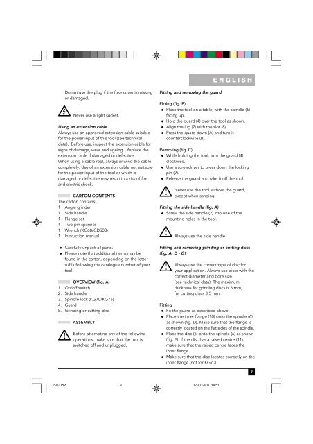
OVERVIEW (fig. A)<br />
1. On/off switch<br />
2. Side handle<br />
3. Spindle lock (<strong>KG70</strong>/<strong>KG75</strong>)<br />
4. Guard<br />
5. Grinding or cutting disc<br />
ASSEMBLY<br />
Before attempting any of the following<br />
operations, make sure that the tool is<br />
switched off and unplugged.<br />
Fitting and removing the guard<br />
ENGLISH<br />
Fitting (fig. B)<br />
◆ Place the tool on a table, with the spindle (6)<br />
facing up.<br />
◆ Hold the guard (4) over the tool as shown.<br />
◆ Align the lug (7) with the slot (8).<br />
◆ Press the guard down (A) and turn it<br />
counterclockwise (B).<br />
Removing (fig. C)<br />
◆ While holding the tool, turn the guard (4)<br />
clockwise.<br />
◆ Use a screwdriver to press down the locking<br />
pin (9).<br />
◆ Release the guard and take it off the tool.<br />
Never use the tool without the guard,<br />
except when sanding.<br />
Fitting the side handle (fig. A)<br />
◆ Screw the side handle (2) into one of the<br />
mounting holes in the tool.<br />
Always use the side handle.<br />
Fitting and removing grinding or cutting discs<br />
(fig. A, D - G)<br />
Always use the correct type of disc for<br />
your application. Always use discs with the<br />
correct diameter and bore size<br />
(see technical data). The maximum<br />
thickness for grinding discs is 6 mm,<br />
for cutting discs 3.5 mm.<br />
Fitting<br />
◆ Fit the guard as described above.<br />
◆ Place the inner flange (10) onto the spindle (6)<br />
as shown (fig. D). Make sure that the flange is<br />
correctly located on the flat sides of the spindle.<br />
◆ Place the disc (5) onto the spindle (6) as shown<br />
(fig. E). If the disc has a raised centre (11),<br />
make sure that the raised centre faces the<br />
inner flange.<br />
◆ Make sure that the disc locates correctly on the<br />
inner flange (not for <strong>KG70</strong>).<br />
SAG.P65 9<br />
17-07-2001, 14:51<br />
9