BRUSA Elektronik AG info@brusa
BRUSA Elektronik AG info@brusa
BRUSA Elektronik AG info@brusa

Erfolgreiche ePaper selbst erstellen
Machen Sie aus Ihren PDF Publikationen ein blätterbares Flipbook mit unserer einzigartigen Google optimierten e-Paper Software.
BSC624-12V_User_Manual_090615.doc<br />
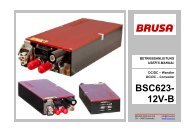
USER’s MANUAL<br />
BETRIEBSANLEITUNG<br />
DC/DC – Converter<br />
DC/DC - Wandler<br />
BSC624<br />
-12V<br />
<strong>BRUSA</strong> <strong>Elektronik</strong> <strong>AG</strong> <strong>info@brusa</strong>.biz<br />
CH - 9466 Sennwald www.brusa.biz
Betriebsanleitung BSC624-12V User’s manual BSC624-12V<br />
Inhaltsverzeichnis<br />
Table of contents<br />
BSC624-12V_User_Manual_090615.doc 2 / 41<br />
1 Vor der Inbetriebnahme Before operation............................................................... 3<br />
2 Sicherheitsmassnahmen For safe use of this unit ................................................... 4<br />
3 Lieferumfang Scope of delivery............................................................... 6<br />
4 Spezifikationen Specifications .................................................................... 7<br />
4.1 Übersicht Overview ................................................................................ 7<br />
4.2 Einführung Introduction ............................................................................ 8<br />
4.3 Terminologie Terminology ............................................................................ 8<br />
4.4 Elektrische Eckdaten Electrical parameters ............................................................. 8<br />
4.5 Mechanische Eckdaten Mechanical parameters........................................................ 10<br />
4.6 Blockschaltbild Block diagram...................................................................... 10<br />
5 Schnittstellen Interfaces......................................................................... 11<br />
5.1 Leistungsanschlüsse Power connectors ................................................................ 11<br />
5.2 Steueranschluss Control interface .................................................................. 12<br />
6 Technische Eigenschaften Technical characteristics................................................ 20<br />
6.1 Interne Stromversorgungen Internal power supplies ....................................................... 20<br />
6.2 Zuverlässigkeit Reliabilty .............................................................................. 22<br />
6.3 EMV – Betrachtungen EMC – considerations......................................................... 26<br />
7 Inbetriebnahme des Gerätes Start-up the device .......................................................... 31<br />
7.1 Befestigung des Geräts im Fahrzeug Mounting of the device in the vehicle .................................. 31<br />
7.2 Anschluss des Gerätes Connecting the device......................................................... 32<br />
7.3 Bedienung des Gerätes Operation of the device ....................................................... 33<br />
7.4 Programmieren der Firmware Download the firmware ....................................................... 33<br />
8 Garantie Warranty .......................................................................... 41
Betriebsanleitung BSC624-12V User’s manual BSC624-12V<br />
1 Vor der Inbetriebnahme<br />
Before operation<br />
Geschätzter Kunde!<br />
Mit dem <strong>BRUSA</strong> DC/DC-Wandler BSC624-12V haben<br />
Sie ein sehr leistungsfähiges und vielseitiges Gerät erworben.<br />
Um dessen Vorzüge zu nutzen und jegliche<br />
Gefahr für Mensch und Material zu vermeiden, lesen<br />
Sie bitte vor der Inbetriebnahme diese Anleitung sorgfältig<br />
durch. Wir empfehlen Ihnen die Anleitung für späteres<br />
Nachschlagen aufzubewahren.<br />
Änderungen an der Betriebsanleitung sind vorbehalten<br />
und werden nicht angekündigt. Holen Sie sich bitte die<br />
aktuelle Version von unserer Homepage:<br />
www.brusa.biz.<br />
BSC624-12V_User_Manual_090615.doc 3 / 41<br />
Dear Customer!<br />
With the <strong>BRUSA</strong> DC/DC-Converter BSC624-12V you<br />
purchased a powerful and versatile product. To take<br />
advantage of its features and to avoid danger for man<br />
and material please read the operating instructions<br />
carefully before operating the unit. We recommend to<br />
keep the user’s manual for later reference.<br />
Changes to the user’s manual are subject to further development<br />
of the device and won’t be announced.<br />
Please download the latest version of this manual on:<br />
www.brusa.biz.
Betriebsanleitung BSC624-12V User’s manual BSC624-12V<br />
2 Sicherheitsmassnahmen<br />
For safe use of this unit<br />
Zu Ihrer Sicherheit For your safety<br />
• Lesen Sie die Anleitung gründlich. • Read the manual carefully.<br />
• Bitte beachten Sie, dass sorgloser Umgang mit höheren<br />
Gleichspannungen zu sehr gefährlichen und<br />
lebensbedrohenden Situationen führen kann.<br />
• Das Gerät produziert Abwärme. Unvorsichtige Berührung<br />
kann zu Verbrennungen führen.<br />
Bitte keine leicht entzündbaren Gegenstände in der<br />
Nähe des Gerätes montieren.<br />
BSC624-12V_User_Manual_090615.doc 4 / 41<br />
• Please note that careless handling of high DC voltages<br />
can be very dangerous and lethal.<br />
• This unit produces waste heat. Touching the hot<br />
unit can lead to injuries and burnings.<br />
Please do not install easy flammable material close<br />
to the unit.
Betriebsanleitung BSC624-12V User’s manual BSC624-12V<br />
Zu Ihrer Sicherheit<br />
• Lassen Sie das Gerät durch einen Fachmann im<br />
Fahrzeug installieren und in Betrieb nehmen.<br />
• Öffnen Sie keinesfalls das Gerät ohne vorherige<br />
Rücksprache mit dem Werk.<br />
• Stecken Sie niemals die Hochspannungsstecker ein<br />
ohne vorher sicherzustellen, dass am Stecker keine<br />
Hochspannung anliegt (z.B.: im Fahrzeug durch<br />
Schütze).<br />
• Trennen Sie niemals die Hochspannungsstecker<br />
vom Gerät ohne vorher sicherzustellen, dass keine<br />
Hochspannung mehr anliegt.<br />
• Verwenden Sie einen Isolationswächter für die Überwachung<br />
der galvanischen Trennung zwischen<br />
Hoch- und Niederspannungskreis.<br />
Um einen Schaden am Gerät zu vermeiden<br />
• Sorgen Sie für ausreichende Kühlung des Gerätes.<br />
Eine niedrige Kühlwassertemperatur kann die Lebensdauer<br />
beträchtlich erhöhen.<br />
• Vermeiden Sie den Betrieb nahe an Wärmequellen<br />
oder in direkter Sonnenstrahlung.<br />
• Trotz des hohen IP-Schutzes empfehlen wir, das<br />
Gerät soweit als möglich von Umwelteinflüssen wie<br />
Regen oder Spritzwasser zu schützen.<br />
BSC624-12V_User_Manual_090615.doc 5 / 41<br />
For your safety<br />
• Have the unit installed and made operational by a<br />
skilled professional.<br />
• Do not open the unit without contacting the manufacturer<br />
before.<br />
• Do not connect the high voltage connectors before<br />
being sure that there is no high voltage on the connector<br />
itself (e.g.: in a vehicle by contactors).<br />
• Never disconnect the high voltage connectors before<br />
being sure that there is no high voltage on the<br />
DC-link anymore.<br />
• Use an isolation failure detector in order to monitor<br />
the galvanic isolation between the high and the low<br />
voltage DC-link.<br />
To prevent from damage of the device<br />
• Ensure sufficient cooling of the device. A low temperature<br />
of the cooling water has a considerable<br />
positive effect on the lifetime.<br />
• Avoid operation of the device next to a heat source<br />
or in direct sunlight.<br />
• Even though the high IP-protection we recommend<br />
to not expose the unit to rain or splash water.
Betriebsanleitung BSC624-12V User’s manual BSC624-12V<br />
3 Lieferumfang<br />
Scope of delivery<br />
Für einen betriebsbereiten DC/DC-Wandler<br />
sind folgende Teile notwendig:<br />
• DC/DC-Wandler BSC624-12V<br />
• Harting Hochspannungssteckverbindung kundenseitig<br />
HAN-Modular Compact:<br />
Tüllengehäuse gerade HAN-Modular Compact<br />
Trägergehäuse HAN-Modular Compact<br />
Buchseneinsatz HAN CC<br />
4mm 2 Krimpkontaktbuchsen<br />
Kabelverschraubung HSK-M-EMV M25x1.5 für<br />
Kabeldurchmesser 9-16mm<br />
• Niederspannungssteckverbindung kundenseitig:<br />
Pluspolsteckergehäuse für 50mm 2 -Kabel<br />
MC-Kontakt SP10AR-N/50<br />
O-Ring<br />
M3x5 Gewindestift<br />
M8/50mm 2 gerader Kabelschuh für 12V-<br />
Minusanschluss<br />
M8/50mm 2 abgewinkelter Kabelschuh für 12V-<br />
Minusanschluss<br />
• 23-poliger Steuerstecker mit Krimpkontakten:<br />
AMPSEAL Buchse: 770680-1<br />
AMPSEAL Kontakte: 770854-1<br />
Drahtquerschnitt: 0.5mm 2<br />
BSC624-12V_User_Manual_090615.doc 6 / 41<br />
A complete set to run the DC/DC-converter:<br />
• DC/DC-converter BSC624-12V<br />
• Harting High voltage connector customer side HAN-<br />
Modular Compact:<br />
Hood top entry HAN-Modular Compact<br />
Carrier hood HAN-Modular Compact<br />
Socket module HAN CC<br />
4mm 2 crimp contact plug sockets<br />
Cable gland HSK-M-EMV M25x1.5 for cable<br />
diameter 9-16mm<br />
• Low voltage connectors customer side:<br />
Plus pole connector housing for 50mm 2 -cable<br />
MC-contact SP10AR-N/50<br />
O-ring seal<br />
M3x5 set screw<br />
M8/50mm 2 straight cable shoe for 12V-minus<br />
connection<br />
M8/50mm 2 right angle cable shoe for 12Vminus<br />
connection<br />
• 23-pole control connector with crimp contacts:<br />
AMPSEAL socket: 770680-1<br />
AMPSEAL contacts: 770854-1<br />
Wire cross section: 0.5mm 2
Betriebsanleitung BSC624-12V User’s manual BSC624-12V<br />
4 Spezifikationen<br />
Specifications<br />
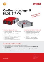
4.1 Übersicht<br />
Overview<br />
HV-Leistungstecker<br />
HV-power connector<br />
Wasseranschlüsse<br />
Cooling pipes<br />
Druckausgleichs - Membran<br />
Pressure balance membrane<br />
BSC624-12V_User_Manual_090615.doc 7 / 41<br />
Steuerstecker<br />
Control connector<br />
LV-Pluspol Leistungstecker<br />
LV-Plus pole power connector<br />
LV-Minuspol<br />
LV-Minus pole<br />
Befestigungslöcher<br />
Mounting holes
Betriebsanleitung BSC624-12V User’s manual BSC624-12V<br />
4.2 Einführung<br />
Introduction<br />
4.3 Terminologie<br />
Terminology<br />
4.4 Elektrische Eckdaten<br />
Electrical parameters<br />
Der BSC624-12V ist ein bidirektionaler DC/DC-Wandler<br />
mit galvanischer Trennung zwischen dem Hochspannungs-<br />
und Niederspannungskreis. Das Gerät basiert<br />
zum einen auf einer serien-resonant arbeitenden Trafostufe,<br />
durch welche die galvanische Trennung realisiert<br />
wird. Zum anderen kann durch zwei zur Rippelreduzierung<br />
verzahnt arbeitende Hochsetz-/Tiefsetzsteller die<br />
gewünschte Spannung im jeweiligen Betriebsmodus<br />
eingestellt werden. Aufgrund der resonanten Topologie<br />
der Trafostufe und der sogenannten Autokommutierung<br />
des Hochsetz-/Tiefsetzstellers werden nicht nur Verluste<br />
auf ein Minimum begrenzt, sondern auch hervorra-<br />
gende EMV-Eigenschaften erreicht.<br />
• Hochspannung, Leistungsanschluss (HV):<br />
Fuel Cell Circuit (FCC), Battery Circuit (BC)<br />
• Niederspannung, Leistungsanschluss (LV):<br />
Bordnetz (AUX)<br />
• Niederspannung, Steueranschluss (LV):<br />
Bordnetz (AUX)<br />
The BSC624-12V is a bidirectional DC/DC-Converter<br />
with galvanic isolation between the high voltage and<br />
low voltage circuit. The device is based on one hand<br />
upon a series-resonant operating transformer stage,<br />
which ensures the galvanic isolation. On the other hand<br />
two buck/boost-converters, that are operated interleaved<br />
in order to reduce ripple currents, allow to adjust<br />
the required voltage level in the corresponding operation<br />
mode. Due to the resonant topology of the transformer<br />
stage and the so-called Autocommutation of the<br />
buck/boost-converter not only losses are reduced to a<br />
minimum but also an excellent EMC-behavior is obtained.<br />
• High voltage, Power interface (HV):<br />
Fuel cell circuit (FCC), Battery circuit (BC)<br />
• Low voltage, Power interface (HV):<br />
Auxiliary supply (AUX)<br />
• Low voltage, Control interface (LV):<br />
Auxiliary supply (AUX)<br />
Value Unit Remarks<br />
Hochspannungsseite High voltage side<br />
Min. Spannung, eingeschränkte Leistung 220 V ULVmax = 14V Min. voltage, reduced performance<br />
Min. Spannung, volle Leistung 240 V Min. voltage, full performance<br />
Max. Spannung, volle Leistung 450 V Max. voltage, full performance<br />
Überspannung, Abschalten der Leistungsstufe >460 V Overvoltage, shut down of power stage<br />
Max. Spannung, kein Betrieb >600 V Gerät kann beschädigt werden / device may be<br />
damaged<br />
Max. voltage, no operation<br />
Verpolung Sicherung löst aus / fuse may blow Reverse polarity<br />
Niederspannungsseite Low voltage side<br />
Nennspannung<br />
14.0 V +/-0.1V Rated voltage<br />
Min. Spannung, volle Leistung 8.0 V Min. voltage, full performance<br />
Max. Spannung, volle Leistung 16.0 V Max. voltage, full performance<br />
Überspannung, Abschaltung der Leistungsstufe<br />
>20.0 V Overvoltage, shut down of power stage<br />
Max. Spannung, kein Betrieb, max. 1min. >25.0 V Gerät kann beschädigt werden / device may be Max. voltage, no operation, max. 1min.<br />
damaged<br />
Verpolung Sicherung löst aus / fuse may blow Reverse polarity<br />
BSC624-12V_User_Manual_090615.doc 8 / 41
Betriebsanleitung BSC624-12V User’s manual BSC624-12V<br />
Leistungsdaten Power rating<br />
LV-Dauerstrom<br />
200 A Continuous LV current<br />
LV-Spitzenstrom<br />
250 A Peak buck mode LV current<br />
HV-Dauerstrom Hochsetzbetrieb 3.6 A @ UHV = 400V, ULV = 8V, η = 90% Continuous boost mode HV current<br />
HV-Spitzenstrom Hochsetzbetrieb 4.5 A @ UHV = 400V, ULV = 8V, η = 90% Peak boost mode HV current<br />
Dauerleistung Tiefsetzbetrieb 2.8 kW @ Nennspannung / @ rated voltage Continuous buck mode output power<br />
Spitzenleistung Tiefsetzbetrieb 3.5 kW @ Nennspannung / @ rated voltage Peak buck mode output power<br />
Dynamisches Verhalten Dynamic performance<br />
Sprungantwort LV-Spannung
Betriebsanleitung BSC624-12V User’s manual BSC624-12V<br />
4.5 Mechanische Eckdaten<br />
Mechanical parameters<br />
Kühlung Thermal<br />
Kühlmedium 50% Water, 50% Ethylenglycol Coolant medium<br />
Kühlmittelvolumen 225 ml Inklusive Anschlussstutzen / Including nozzle Coolant volume<br />
Min. Kühlmitteltemperatur -40 °C Min. coolant temperature<br />
Max. Kühlmitteltemperatur 65 °C Max. coolant temperature<br />
Durchflussrate<br />
>4 l/min Cooling flow rate<br />
Druckabfall<br />
Betriebsanleitung BSC624-12V User’s manual BSC624-12V<br />
5 Schnittstellen<br />
Interfaces<br />
5.1 Leistungsanschlüsse<br />
Power connectors<br />
1<br />
3<br />
2<br />
4<br />
2<br />
1<br />
Hochspannungs – Steckverbindung:<br />
Nr.<br />
1 IL1<br />
2 IL2<br />
3 HV+<br />
4 HV-<br />
Niederspannungs – Steckverbindung:<br />
Beim LV-Pluspolstecker handelt es sich um einen sogenannten<br />
„Push-Pull-Stecker“. Der Stecker muss also<br />
ganz hineingedrückt werden, um die Verbindung zu trennen.<br />
Nr.<br />
1 12V+<br />
Interlock:<br />
Abk. Funktion<br />
Interlock<br />
Interlock<br />
Hochspannung Plus<br />
Hochspannung Minus<br />
Abk. Funktion<br />
Bordnetz Plus<br />
2 GND Bordnetz Minus / Fahrzeugmasse<br />
• Mittels dieser Funktion kann überprüft werden, ob die<br />
Stecker ordnungsgemäss angeschlossen sind, sodass<br />
davon abhängig entsprechende Massnahmen<br />
ergriffen werden können:<br />
Durch die voreilenden Interlock-Kontakte wird<br />
beim Trennen der HV-Steckverbindung ein Fehler<br />
erkannt und das Gerät unmittelbar abgeschaltet,<br />
sodass ein möglicher Lichtbogen verhindert<br />
wird.<br />
Die Hochspannung im Gerät wird beim Erkennen<br />
einer getrennten HV-Steckverbindung unverzüglich<br />
mittels der ohnehin vorhandenen internen<br />
HV-Versorgung entladen (
Betriebsanleitung BSC624-12V User’s manual BSC624-12V<br />
5.2 Steueranschluss<br />
Control interface<br />
5.2.1 Übersicht<br />
Overview<br />
1 8<br />
9 15<br />
16 23<br />
Steuerstecker (23-polig):<br />
Nr.<br />
Abk. Funktion<br />
1 GND Masse (Bordnetz Minus, Klemme 31)<br />
2 AUX +12V (Bordnetz Plus, Klemme 30)<br />
3 EN Enable (Power ON, Klemme 15)<br />
4 DO0 Digitaler Ausgang 1 (programmierbar)<br />
5 DO1 Digitaler Ausgang 2 (programmierbar)<br />
6 DO2 Digitaler Ausgang 3 (programmierbar)<br />
7 DO3 Digitaler Ausgang 4 (programmierbar)<br />
8 PG1 Analoge Masse (für Pins 21 – 23)<br />
9 CNL<br />
10 CNH<br />
CAN Low<br />
CAN High<br />
11 TXD RS232 Transmit (9-pol D-Sub: Pin 2)<br />
12 RXD RS232 Receive (9-pol D-Sub: Pin 3)<br />
13 PRO<br />
14 PG2<br />
Enable Firmware-Programmierung<br />
Reserve-Masse<br />
15 PG3 RS232 Masse (9-pol D-Sub: Pin 5)<br />
16 DI0 Digitaler Eingang 1<br />
17 DI1 Digitaler Eingang 2<br />
18 DI2 Digitaler Eingang 3<br />
19 IL1 Interlock - Signaleinspeisung<br />
20 IL2 Interlock - Signaleinspeisung<br />
21 AI1 Analoger Eingang 1 (programmierbar)<br />
22 AI2 Analoger Eingang 2 (programmierbar)<br />
23 AI3 Analoger Eingang 3 (programmierbar)<br />
BSC624-12V_User_Manual_090615.doc 12 / 41<br />
Control connector (23-pole):<br />
No. Abbr. Function<br />
1 GND Ground (Auxiliary voltage minus, terminal<br />
31)<br />
2 AUX +12V (Auxiliary voltage plus, terminal<br />
30)<br />
3 EN Enable (Power ON, terminal 15)<br />
4 DO0 Digital Output 1 (programmable)<br />
5 DO1 Digital Output 2 (programmable)<br />
6 DO2 Digital Output 3 (programmable)<br />
7 DO3 Digital Output 4 (programmable)<br />
8 PG1 Analog Ground (for pins 21 – 23)<br />
9 CNL<br />
10 CNH<br />
CAN low<br />
CAN high<br />
11 TXD RS232 Transmit (9-pole D-Sub: Pin 2)<br />
12 RXD RS232 Receive (9-pole D-Sub: Pin 3)<br />
13 PRO Enable firmware download<br />
14 PG2<br />
Reserve Ground<br />
15 PG3 RS232 Ground (9-pole D-Sub: Pin 5)<br />
16 DI0 Digital Input 1<br />
17 DI1 Digital Input 2<br />
18 DI2 Digital Input 3<br />
19 IL1 Interlock – Signal Input<br />
20 IL2 Interlock – Signal Input<br />
21 AI1 Analog Input 1 (programmable)<br />
22 AI2 Analog Input 2 (programmable)<br />
23 AI3 Analog Input 2 (programmable)
Betriebsanleitung BSC624-12V User’s manual BSC624-12V<br />
5.2.2 Beschreibung der einzelnen<br />
Steuersteckerpins<br />
Description of the control connector<br />
pins<br />
5.2.2.1 GND (Masse, Ground), Pin 1<br />
Interne Beschaltung<br />
Internal Circuit<br />
GND (1)<br />
Gehäuse/housing<br />
5.2.2.2 AUX (Bordnetz, Auxiliary Supply),<br />
Pin 2<br />
Interne Beschaltung<br />
Internal Circuit<br />
AUX (2) 100uH 1.5A<br />
1.76uF<br />
36V<br />
10uF<br />
10.7V<br />
Supply<br />
11.3V<br />
Supply<br />
1MΩ<br />
23.5µF<br />
12.5V<br />
12.5V- HV<br />
Supply<br />
5V<br />
Supply<br />
5V<br />
• Direkte Verbindung zur Masse der Steuereinheit.<br />
• Die Signalmasse ist nur kapazitiv mit dem Gehäuse<br />
verbunden, d.h. die Signalmasse ist von der Leistungsmasse<br />
(Gehäuse) galvanisch getrennt, um<br />
Masseschleifen zu vermeiden.<br />
• Bei Verdrahtung von BSC624-12V-Steuersignalen<br />
mit anderen Fahrzeug-Komponenten (z.B. Fahrantrieb,<br />
Bordbatterie, Batteriemanagement, Brennstoffzelle)<br />
muss hier die Fahrzeug-Masse angeschlossen<br />
werden.<br />
• Das Gerät wird – wenn keine Spannung am HV-<br />
Leistungsstecker anliegt – über diesen Anschluss<br />
vom Bordnetz versorgt. Dann kann mit EN = „High“<br />
über CAN oder RS232 mit dem Gerät kommuniziert<br />
werden. Folgende Funktionen sind bei ausschliesslicher<br />
Versorgung vom Bordnetz (Steuerstecker) sichergestellt:<br />
Senden und Empfangen von CAN-Informationen<br />
Kommunikation über RS232 (Monitor-<br />
Programm)<br />
Programmieren der Firmware<br />
Spannungs-, Strom und Temperaturmessung<br />
BSC624-12V_User_Manual_090615.doc 13 / 41<br />
• Direct connection to control unit ground .<br />
• The signal ground is only coupled capacitively to<br />
the housing, which means the signal ground is<br />
galvanically isolated from the power ground (housing),<br />
in order to avoid ground loops.<br />
• If BSC624-12V control signals are connected to<br />
other vehicle components (e.g. propulsion system,<br />
on-board battery, battery management system,<br />
fuel cell) the vehicle’s ground must be connected<br />
to this terminal.<br />
• The device will be supplied – if no voltage is applied<br />
to the HV-power connector – by the auxiliary<br />
supply. Communication over CAN or RS232 can<br />
be enabled by setting EN = “high”. If only auxiliary<br />
supply (control connector) is applied, following<br />
functions are available:<br />
Send and receive CAN-messages<br />
Communication via RS232 (monitor-program)<br />
Download of firmware<br />
Voltage and temperature measurement<br />
Spannung an AUX (2) Enable (3), Klemme 15 RUN-Command (über HV-Spannung Stromaufnahme an<br />
in V<br />
CAN gesendet) in V<br />
AUX (2) in mA<br />
Voltage at AUX (2) in V Enable (3), Terminal 15 RUN-Command (sent HV-voltage in V Current consumption<br />
by CAN)<br />
at AUX (2) in mA<br />
12.0 0 0 0 0.0552<br />
13.8 0 0 0 0.0583<br />
12.0 1 0 0 232.9000<br />
13.8 1 0 0 203.9000<br />
12.0 1 0 280 5.4400<br />
13.8 1 0 280 7.4000
Betriebsanleitung BSC624-12V User’s manual BSC624-12V<br />
5.2.2.3 EN (Enable, Power ON), Pin 3<br />
Interne Beschaltung<br />
Internal Circuit<br />
EN (3)<br />
47nF<br />
33V<br />
11.3V Supply<br />
Enable<br />
120kΩ<br />
2.7kΩ<br />
11.3V<br />
Supply<br />
100nF<br />
2.7kΩ<br />
5V<br />
Supply<br />
5V Supply<br />
Enable<br />
10n0F<br />
23.5kΩ<br />
220pF<br />
22kΩ<br />
5V<br />
1,0V<br />
3,3V<br />
Schmitt<br />
Trigger<br />
• Bei Anlegen einer Spannung an AUX und mit EN =<br />
„High“ (+7V...32V) wird das Gerät in den betriebsbereiten<br />
Modus versetzt. Sinnvollerweise erfolgt dies<br />
durch eine Verbindung des Enable-Pins über einen<br />
Schalter mit dem Bordnetz.<br />
• Um eine neue Firmware zu programmieren, ist es<br />
nicht erforderlich, dass EN = „High“ ist.<br />
• Auch wenn am HV-Stecker Hochspannung anliegt,<br />
wird die geräteinterne Logik nur dann versorgt, wenn<br />
der Pin EN = „High“ ist (oder Pin PROG = „High“ ist).<br />
BSC624-12V_User_Manual_090615.doc 14 / 41<br />
• By applying a voltage to AUX and by setting EN =<br />
„high“ (+7V...32V) the device will be ready to operate.<br />
Reasonably this is realized by using a<br />
switch in order to connect the enable-pin to the<br />
auxiliary supply.<br />
• In order to download a new firmware, EN does not<br />
have to be „high”.<br />
• Even when high voltage is applied to the HVconnector,<br />
the device internal logic is only supplied,<br />
if the pin EN = „high“ (or pin PROG =<br />
“high”).
Betriebsanleitung BSC624-12V User’s manual BSC624-12V<br />
5.2.2.4 DO0 – DO3 (Digitale Ausgänge, Digital<br />
Outputs), Pins 3 - 7<br />
Interne Beschaltung<br />
Internal Circuit<br />
DO0 - DO3 (4 - 7)<br />
10nF<br />
33V<br />
500Ω<br />
AUX<br />
• Mit diesen vier programmierbaren digitalen Ausgängen<br />
können niederfrequente Anwendungen realisiert<br />
werden:<br />
Ansteuerung von LEDs für Statusfunktionen<br />
(z.B. Unter- bzw. Überspannung, Überschreitung<br />
einer Stromgrenze, Temperatur-Derating,...).<br />
Ansteuerung von anderen externen Komponenten<br />
(PWM für Anzeigeinstrumente, Relais, kleine<br />
Lüfter,...).<br />
• Alle vier digitalen Ausgänge weisen folgende Merkmale<br />
auf:<br />
RDSON = 1,7Ω bei TA = 25°C<br />
VOUTmax = 32V<br />
VCLAMP = 45V (Spannungsfestigkeit für induktive<br />
Lasten)<br />
Kurzschlussfestigkeit (Imax = 700mA).<br />
Abschaltung bei zu hoher Temperatur aufgrund<br />
von Überbelastung.<br />
• Bei Auftreten eines Fehlers an einem Ausgang sind<br />
die restlichen Ausgänge weiter funktionstauglich,<br />
wenn es durch den einen Fehler nicht zu einer Abschaltung<br />
bei den restlichen Ausgängen aufgrund zu<br />
hoher Temperatur führt.<br />
• Die Ausgänge können mit Frequenzen bis zu 10kHz<br />
betrieben werden. Um auch bei diesen Frequenzen<br />
noch ordentliche Signalverläufe zu ermöglichen, ist<br />
jeder Ausgang mit einem 500Ω/2W Pullup-<br />
Widerstand beschaltet.<br />
BSC624-12V_User_Manual_090615.doc 15 / 41<br />
• With these four programmable digital outputs low<br />
frequency applications can be realized:<br />
Drive LEDs for status functions (e.g.: under-<br />
or overvoltage, exceeding of current limit,<br />
temperature derating,...).<br />
Drive other external components (PWM for<br />
display instruments, relays, small fans,...).<br />
• All four digital outputs show the following features:<br />
RDSON = 1,7Ω at TA = 25°C<br />
VOUTmax = 32V<br />
VCLAMP ≥ 45V (clamping voltage for inductive<br />
loads)<br />
Short circuit detection (Imax = 700mA).<br />
Over-temperature shutdown due to overload.<br />
• In case of such a failure at one of the outputs the<br />
other outputs remain still fully functional as long as<br />
such a failure does not lead to over-temperature<br />
shut down of the other outputs.<br />
• All outputs can be driven with a frequency up to<br />
10kHz. In order to ensure proper signals even<br />
such frequencies, each output has a 500Ω/2W<br />
pull-up resistor.
Betriebsanleitung BSC624-12V User’s manual BSC624-12V<br />
5.2.2.5 PG1 – PG3 (Analoge Masse, Analog<br />
Ground), Pins 8, 14, 15<br />
Interne Beschaltung<br />
Internal Circuit<br />
PG1 – PG3 (8, 14, 15)<br />
5.2.2.6 CNH, CNL (CAN-Bus, CAN-Interface),<br />
Pins 9, 10<br />
Interne Beschaltung<br />
Internal Circuit<br />
CNH (10)<br />
CNL (9)<br />
47pF<br />
47pF<br />
33V<br />
33V<br />
51uH<br />
51uH<br />
120Ω<br />
300mA<br />
Termination<br />
resistor is<br />
optional<br />
4.7µF<br />
CAN-Transceiver<br />
and galvanic<br />
isolation<br />
• Zur Vereinfachung der externen Verdrahtung stehen<br />
drei zusätzliche Masse-Anschlüsse zur Verfügung.<br />
Diese sind über je eine PTC-Sicherung mit der Versorgungs-Masse<br />
GND verbunden.<br />
• Folgende Zuordnung wird vorgeschlagen:<br />
Nr.<br />
Abk. Funktion<br />
8 PG1 Analoge Masse (für Pins 21 - 23)<br />
14<br />
PG2 Reserve Masse<br />
15 PG3 RS232 - Masse (9-pol D-Sub: Pin 5)<br />
Die CAN-Schnittstelle weist folgende Eigenschaften<br />
auf:<br />
• CAN 2.0 B, 500 kBit (optional 1Mbit)<br />
• Die CAN-Schnittstelle weist eine Potentialtrennung<br />
von der Masse und den übrigen Steuersignalen auf,<br />
um Störungen durch Potentialverschiebungen zu<br />
vermeiden.<br />
• Der 120Ω Abschlusswiderstand kann optional bestückt<br />
werden.<br />
• Über die CAN-Schnittstelle können Informationen<br />
gemäss der vom Kunden festgelegten CAN-Matrix<br />
gesendet und empfangen werden.<br />
BSC624-12V_User_Manual_090615.doc 16 / 41<br />
• In order to simplify external wiring, three additional<br />
ground pins are available. Each pin is connected<br />
to the supply’s ground GND by a ptc-fuse.<br />
• Following pin assignment is suggested:<br />
Nr.<br />
Abbr. Function<br />
8 PG1 Analog Ground (for pins 21 - 23)<br />
14<br />
PG2 Reserve Ground<br />
15 PG3 RS232 Ground (9-pol D-Sub: Pin 5)<br />
The CAN interface has following characteristics:<br />
• CAN 2.0 B, 500 kBit (optional 1Mbit)<br />
• Galvanic isolation from ground and all other control<br />
signals in order to avoid interferences caused<br />
by ground offset voltages.<br />
• The 120Ω termination resistor can be mounted<br />
optionally.<br />
• The CAN interface allows to transmit and receive<br />
messages according to the CAN-matrix defined by<br />
the customer.
Betriebsanleitung BSC624-12V User’s manual BSC624-12V<br />
5.2.2.7 TXD, RXD (RS232-Schnittstelle,<br />
RS232-Interface), Pins 11, 12<br />
Interne Beschaltung<br />
Internal Circuit<br />
TXD (11)<br />
RXD (12)<br />
470pF<br />
470pF<br />
33V<br />
33V<br />
100Ω<br />
100Ω<br />
15V<br />
10V<br />
200Ω<br />
200Ω<br />
470pF<br />
470pF<br />
RS232-<br />
Transeiver<br />
5.2.2.8 PRO (Enable Firmware-<br />
Programmierung, Enable firmware<br />
download), Pin 13<br />
Interne Beschaltung<br />
Internal Circuit<br />
PRO (13)<br />
47nF<br />
33V<br />
11.3V Supply<br />
Enable<br />
120kΩ<br />
2.7kΩ<br />
11.3V<br />
Supply<br />
100nF<br />
2.7kΩ<br />
5V<br />
Supply<br />
5V Supply<br />
Enable<br />
10n0F<br />
23.5kΩ<br />
220pF<br />
22kΩ<br />
5V<br />
1,0V<br />
3,3V<br />
Schmitt<br />
Trigger<br />
• Das RS232-Interface ermöglicht eine direkte serielle<br />
Verbindung zwischen dem BSC624-12V und einem<br />
Computer. Die dafür notwendige Software kann von<br />
der Homepage www.brusa.biz heruntergeladen werden.<br />
Folgende Funktionen werden unterstützt:<br />
Anzeige der Momentanwerte von Strom, Spannung,<br />
Leistung und Temperatur<br />
(Monitorprogramm).<br />
Programmieren der von <strong>BRUSA</strong> mitgelieferten<br />
oder nachgereichten Firmware (durch Setzen<br />
von PRO = „High“). Für weitere Informationen<br />
zum Programmieren kontaktieren Sie bitte direkt<br />
<strong>BRUSA</strong>.<br />
Belegung der 9-poligen D-Sub Kabelbuchse:<br />
TXD (11)<br />
RXD (12)<br />
2<br />
3<br />
PG3 (15) 5<br />
9-polige D-Sub<br />
Kabelbuchse<br />
• Dieser Anschluss wird ausschliesslich für das Programmieren<br />
einer neuen Firmware aktiviert (PRO =<br />
„High“), wobei dann EN nicht „High“ sein muss.<br />
• Sowohl bei Versorgung von HV als auch vom Bordnetz<br />
löst PRO = „High“ folgende Vorgänge aus:<br />
Falls das Gerät im Betrieb ist, wird dieser gestoppt.<br />
Das Gerät ist dann empfangsbereit und kann<br />
über die serielle Schnittstelle programmiert werden.<br />
• Das Programmieren einer neuen Firmware darf nur<br />
in Absprache mit <strong>BRUSA</strong> durchgeführt werden. Die<br />
Firmware wird dann allenfalls per Email zur zugestellt.<br />
BSC624-12V_User_Manual_090615.doc 17 / 41<br />
• The RS232 interface provides a direct serial connection<br />
between the BSC624-12V and a computer.<br />
The necessary software can be<br />
downloaded from our homepage www.brusa.biz.<br />
Following functions are provided:<br />
Display the actual current, voltage, power and<br />
temperature values (monitor program).<br />
Download the firmware provided by <strong>BRUSA</strong><br />
(by setting PRO = “high”). For further information<br />
regarding the download please contact<br />
directly <strong>BRUSA</strong>.<br />
Pin assignment of the 9-pole D-sub socket:<br />
TXD (11)<br />
RXD (12)<br />
2<br />
3<br />
PG3 (15) 5<br />
9 pin D-Sub<br />
connector, female<br />
• This pin is exclusively activated (PRO = „high“) to<br />
download a new firmware, whereas EN does not<br />
have to be „high”.<br />
• PRO = „high” causes the following actions regardless<br />
of supplying the device from HV or auxiliary<br />
supply:<br />
If the device is in operation, it will be shut<br />
down.<br />
The device is then ready to be programmed<br />
via the serial interface.<br />
• The download of a new firmware may only be<br />
done with agreement of <strong>BRUSA</strong>. A new firmware<br />
can be provided by email then.
Betriebsanleitung BSC624-12V User’s manual BSC624-12V<br />
5.2.2.9 DI0 – DI2 (Digitale Eingänge, Digital<br />
Inputs), Pins 16 – 18<br />
Interne Beschaltung<br />
Internal Circuit<br />
DI0 – DI2 (16 - 18)<br />
10nF<br />
33V<br />
23.5kΩ<br />
22kΩ<br />
220pF<br />
5V<br />
1,0V<br />
3,3V<br />
Schmitt<br />
Trigger<br />
5.2.2.10 IL1, IL2 (Interlock), Pins 19, 20<br />
Interne Beschaltung<br />
Internal Circuit<br />
IL1 (19)<br />
IL2 (20)<br />
10nF<br />
10nF<br />
10uF<br />
12mH<br />
12mH<br />
30kΩ<br />
62Ω<br />
100nF<br />
470pF<br />
IL1 (1)<br />
IL2 (2)<br />
470pF<br />
51uH<br />
51uH<br />
5V<br />
uC<br />
High voltage<br />
power connector<br />
Interlock-Error<br />
(INTL_OC_ext*)<br />
Int. Interlock<br />
Processing<br />
(INTL_OC_int*)<br />
• Mit diesen drei Eingängen können verschiedene<br />
Funktionen realisiert werden wie folgender Vorschlag<br />
zeigt:<br />
DI0: Hochsetzbetrieb<br />
DI1: Tiefsetzbetrieb<br />
DI2: Spannungs- oder Stromregelmodus<br />
• Die Interlock-Verbindung ist eine sicherheitsrelevante<br />
Funktion, die intern verarbeitet wird, aber auch durch<br />
ein übergeordnetes System (Bsp.: Fahrzeugsystem)<br />
ausgewertet werden kann. Die Interlock-Verbindung<br />
ist durch die HV-Steckverbindung geschleift (Brücke<br />
im kundenseitigen HV-Stecker notwendig) und erlaubt<br />
so die Überprüfung, ob dieser Stecker ordnungsgemäss<br />
angeschlossen ist.<br />
• Falls nicht nur die eigene HV-Steckverbindung, sondern<br />
auch jene von zusätzlichen Geräten überprüft<br />
werden soll, muss die Interlockschleife durch sämtliche<br />
Geräte geführt werden. In diesem Fall muss das<br />
Interlock-Signal bei Pin 19 bzw. 20 eingespeist werden,<br />
wobei die Polarität keine Rolle spielt. Der eingeprägte<br />
Strom muss im Normalfall zwischen 18-22mA<br />
liegen, unter etwa 10mA wird ein Interlock-Fehler detektiert.<br />
• Falls nun irgendwelche Stecker nicht richtig kontaktiert<br />
sind, ist die Schleife offen und es wird intern ein<br />
Fehler erkannt. Dies führt unverzüglich zum Abschalten<br />
des Geräts.<br />
• Die LV-Steckverbindung ist im Interlockkreis nicht integriert!<br />
• Die interne Interlock-Erkennung funktioniert unabhängig<br />
von der Verwendung der externen Erkennung.<br />
BSC624-12V_User_Manual_090615.doc 18 / 41<br />
• With these three inputs various functions can be<br />
realized as the following proposal shows:<br />
DI0: Boost mode<br />
DI1: Buck mode<br />
DI2: Voltage or current regulation mode<br />
• The interlock is a safety relevant function, which is<br />
processed internally but may also be valuated by<br />
a superior system (e.g.: vehicle system). The interlock<br />
is looped through the HV-connection<br />
(bridge in customer side HV connector necessary)<br />
and allows therefore to monitor, if this connector is<br />
connected properly to the device.<br />
• If not only the own HV-connection, but also those<br />
of additional devices has to be monitored, the interlock<br />
has to be looped through all such devices.<br />
In this case the interlock-signal has to be fed in at<br />
pin 19, resp. 20, whereas the polarity does not<br />
matter. The injected current must be in the range<br />
of 18-22mA in normal case, below 10mA interlockerror<br />
will be detected.<br />
• If the HV- or control connector is not connected<br />
properly to the device, the loop is open and an error<br />
will be detected internally. This leads to an<br />
immediate shut-down of the device.<br />
• The LV-connection is not integrated in the interlock-circuit!<br />
• The internal interlock-detection works independently<br />
of the use of the external detection.
Betriebsanleitung BSC624-12V User’s manual BSC624-12V<br />
5.2.2.11 AI1 – AI3 (Analoge Eingänge, Analog<br />
Inputs), Pins 21 – 23<br />
Interne Beschaltung<br />
Internal Circuitp<br />
AI1 – AI3 (21 - 23)<br />
10nF<br />
I = 1mA<br />
150Ω<br />
10nF<br />
5V<br />
33kΩ<br />
Analog<br />
Multiplexer<br />
22kΩ<br />
5V<br />
Analog<br />
Multiplexer<br />
uC<br />
• Mit diesen drei analogen Eingängen können jeweils<br />
zwei unterschiedliche Funktionen realisiert werden:<br />
1mA – Stromquelle für externes 5kΩ Potentiometer<br />
33kΩ Pull-up – Widerstand für externen 33kΩ<br />
NTC-Temperatursensor.<br />
• Jeder der drei analogen Eingänge kann individuell<br />
gemäss Kundenanforderung programmiert werden.<br />
Bei der Einstellung aller drei Eingänge als Stromquelle<br />
können z.B. folgende Funktionen realisiert werden:<br />
AI1: Spannungsregelung LV<br />
AI2: Stromlimit Buck-Mode<br />
AI3: Stromlimit Boost-Mode<br />
• Bei der Einstellung zur Temperaturmessung (Tmin =<br />
25°C) von externen Komponenten ist z.B. folgende<br />
Konfiguration möglich:<br />
AI1: Batterietemperatur<br />
AI2: Kühlwassertemperatur<br />
AI3: Reserve<br />
BSC624-12V_User_Manual_090615.doc 19 / 41<br />
• With each of these three analog inputs two different<br />
functions can be realized:<br />
1mA – current source for an external 5kΩ potentiometer<br />
33kΩ Pull-up – resistor for external 33kΩ<br />
NTC-temperature sensor.<br />
• Each of these three analog inputs can be programmed<br />
individually according to the customer’s<br />
requirements. If all three inputs are configured as<br />
current source, the following functions can be realized:<br />
AI1: Voltage regulation LV<br />
AI2: Current limit buck-mode<br />
AI3: Current limit boost-mode<br />
• If the inputs are configured for temperature measurement<br />
(Tmin = 25°C) of external components, the<br />
following configuration is proposed:<br />
AI1: Battery temperature<br />
AI2: Cooling water temperature<br />
AI3: Reserve
Betriebsanleitung BSC624-12V User’s manual BSC624-12V<br />
6 Technische Eigenschaften<br />
Technical characteristics<br />
6.1 Interne Stromversorgungen<br />
Internal power supplies<br />
AUX (2) 100uH 1.5A<br />
1.76uF<br />
GND (1)<br />
EN (3)<br />
PRO (13)<br />
47nF<br />
33V<br />
47nF<br />
36V<br />
10uF<br />
120kΩ<br />
2.7kΩ<br />
10.7V/0.1A<br />
Supply<br />
11.3V/1A<br />
Supply<br />
• Das Gerät kann prinzipiell sowohl von HV als auch<br />
von AUX(2) versorgt werden, wobei für die vollständige<br />
Betriebsbereitschaft die 12.5V/2.5A-Versorgung<br />
aktiv sein muss. Diese läuft bei einer HV-Spannung<br />
von etwa 75V an und deaktiviert durch die höhere<br />
Ausgangsspannung automatisch die 11.3V/1A-<br />
Versorgung von AUX (2), um den Stromverbrauch ab<br />
Bordnetz zu reduzieren.<br />
• Die 5V-Versorgung wird erst gewährleistet, wenn<br />
entweder EN (3) oder PRO (13) mit AUX (2) verbunden<br />
wird. Zusätzlich verfügt der uC über Enable1 eine<br />
Selbsthaltefunktion.<br />
BSC624-12V_User_Manual_090615.doc 20 / 41<br />
33V<br />
100nF<br />
HV<br />
12.5V/2.5A<br />
Supply<br />
11.3V Supply<br />
Enable<br />
2.7kΩ<br />
5V/1A<br />
Supply<br />
5V Supply<br />
Enable<br />
100nF<br />
5V-CAN<br />
Supply<br />
+6V/0.1A<br />
Supply<br />
-6V/0.1A<br />
Supply<br />
10kΩ<br />
Driver<br />
Galvanically<br />
isolated<br />
CAN supply<br />
Controller<br />
PWM-Unit<br />
Regulation &<br />
measurement<br />
circuits<br />
uC-Enable 1<br />
• The device can be supplied from HV as well as<br />
from AUX (2), whereas for the complete ready<br />
status the 12.5V/2.5A-supply has to be active.<br />
This supply starts operating at a HV-voltage of<br />
approximately 75V and automatically deactivates<br />
then due to the higher output voltage the<br />
11.3V/1A-supply from AUX (2), in order to reduce<br />
the current consumption from the auxiliary voltage.<br />
• The 5V-supply will be provided, if either EN (3) or<br />
PRO (13) will be connected to AUX (2). Additionally<br />
the uC features with Enable1 a latch-funtion.
Betriebsanleitung BSC624-12V User’s manual BSC624-12V<br />
• Um bei Bedarf einen autarken Betrieb des Geräts zu<br />
gewährleisten, ist eine 10.7V/0.1A-Versorgung implementiert.<br />
Auf diese Weise kann beispielsweise EN<br />
(3) durch eine Verbindung mit AUX (2) im kundenseitigen<br />
Stecker aktiviert werden, sodass das Gerät immer<br />
eingeschaltet ist.<br />
• Die 12.5V/2.5A-Versorgung ist ebenfalls mit der –<br />
auch im Hoch-/Tiefsetzsteller eingesetzten – Autokommutierung-Topologie<br />
realisiert. Diese Speisung<br />
ist galvanisch vom Hochspannungskreis getrennt und<br />
funktioniert zudem ohne Optokoppler.<br />
• Im Hochsetzstellbetrieb werden die Treiber beim<br />
Hochstarten zu Beginn von AUX(2) versorgt.<br />
• Sämtliche Versorgungsschaltkreise sind kurzschlussfest.<br />
• Die Signalmasse (GND (1)) ist von der Leistungsmasse<br />
(LV-) galvanisch getrennt, um Potentialverschleppungen<br />
bzw. Masseschleifen zu verhindern.<br />
BSC624-12V_User_Manual_090615.doc 21 / 41<br />
• A 10.7V/0.1A-supply is implemented, in order to<br />
ensure an autarkic operation of the device, if required.<br />
Thus, EN (3) for instance could be activated<br />
by a connection to AUX (2) in the customerside<br />
connector, so that the device will be permanently<br />
switched on.<br />
• The 12.5V/2.5A-supply is realized again with the –<br />
also in the buck/boost converter used – Auto-<br />
Commutation-topology. This supply is galvanically<br />
isolated from the high voltage circuit and furthermore<br />
functions without an optocoupler.<br />
• In boost mode the drivers will be supplied from<br />
AUX (2) in the very beginning of the start-up.<br />
• All supply circuits are short-circuit-proof.<br />
• The signal ground (GND (1)) is galvanically isolated<br />
from the power ground (LV-), in order to<br />
avoid accidental energisation, resp. ground loops.
Betriebsanleitung BSC624-12V User’s manual BSC624-12V<br />
6.2 Zuverlässigkeit<br />
Reliabilty<br />
6.2.1 Überlastschutz - Derating<br />
Overload protection – derating<br />
Rückregelung aufgrund Trafotemperatur<br />
Derating due to transformer temperature<br />
ILVmax/A<br />
250<br />
106<br />
-10A/°C<br />
131<br />
T/°C<br />
Rückregelung aufgrund Schaltertemperatur<br />
Derating due to switch temperature<br />
ILVmax/A<br />
250<br />
95<br />
-10A/°C<br />
120<br />
T/°C<br />
Abschalten aufgrund Schaltertemperatur<br />
von Hoch-/Tiefsetzsteller<br />
Shut down due to temperature of buck/boost<br />
switch<br />
ILVmax/A<br />
250<br />
80 81<br />
T/°C<br />
• Um<br />
das Gerät vor Überlastung zu schützen, wird die<br />
Temperatur von einzelnen Bauteilen erfasst, sodass<br />
bei Erreichen eines bestimmten Werts automatisch<br />
der maximal mögliche Strom zurückgeregelt wird.<br />
Folgende Bauteiltemperaturen werden hierfür erfasst<br />
und verarbeitet:<br />
Schalter der Trafostufe, HV-seitig (2 von 8)<br />
Schalter der Trafostufe, LV-seitig (2 von 8)<br />
Wicklung der HF-Transformatoren (2 von 2)<br />
• Aufgrund der niedrigen Verluste der Schalter des<br />
Hoch-/Tiefsetzstellers sowie der effizienten Kühlung<br />
weist diese gemessene Schaltertemperatur nur eine<br />
geringfügige höhere Temperatur gegenüber jener der<br />
Kühlflüssigkeit auf. Daher gibt diese Temperatur<br />
auch Aufschluss über die im Gerät vorherrschende<br />
Umgebungstemperatur. Damit Bauteile keinen Schaden<br />
nehmen können bzw. deren Lebensdauer nicht<br />
negativ beeinflusst wird, wird das Gerät bei einer<br />
Temperatur von 81°C abgeschaltet. Erst, wenn die<br />
Temperatur wieder unter 80°C sinkt, kann das Gerät<br />
wieder eingeschaltet werden.<br />
Schalter des Hoch-/Tiefsetzstellers (2 von 8)<br />
• Da über die CAN-Schnittstelle der aktuell transferierbare<br />
Strom (LVCUR_AVL) zurückgemeldet wird, ist<br />
erkennbar, ob das Gerät im Rückregelmodus ist.<br />
• Wenn das Gerät aufgrund zu hoher Temperaturen<br />
schlussendlich abschaltet, wird ein entsprechender<br />
Fehler ausgegeben (E_OVERTEMP).<br />
BSC624-12V_User_Manual_090615.doc 22 / 41<br />
• In order to protect the device in case of overload,<br />
the temperature of specific components is monitored,<br />
so that as soon as a certain value is<br />
reached, the maximum available current will be<br />
automatically derated. Following temperatures are<br />
measured and processed:<br />
Switch of transformer stage, HV-side (2 of 8)<br />
Switch of transformer stage, LV-side (2 of 8)<br />
Coil of HF-transformers (2 of 2)<br />
• Due to the low losses of the switches of the<br />
buck/boost-converter as well as due to the efficient<br />
cooling the measured temperature of this<br />
switch shows only a little higher temperature referred<br />
to the that of the coolant. Therefore this<br />
temperature gives information about the predominating<br />
ambient temperature inside the device. In<br />
order to protect components from damage, respectively<br />
to avoid negative impact on their lifetime,<br />
the device will be shut off at a temperature of<br />
81°C. As soon as the temperature decreases below<br />
80°C, the device can be switched on again.<br />
Switch of buck/boost stage (2 of 8)<br />
• Since the actual available current that can be<br />
transferred will be communicated by CAN<br />
(LVCUR_AVL), it can be detected, if the device is<br />
in derating-mode.<br />
• If the device finally shuts off because of too high<br />
temperatures, an error is set (E_OVERTEMP).
Betriebsanleitung BSC624-12V User’s manual BSC624-12V<br />
6.2.2 Kurzschlussschutz<br />
Short circuit protection<br />
6.2.3 HV-Überspannungs-Abschaltung<br />
HV-Overvoltage shut-down<br />
• Da die Trafostufe aufgrund ihrer resonant taktenden<br />
Topologie einen bestimmten Innenwiderstand hat, ist<br />
diese und damit das Gerät prinzipiell kurzschlussfest.<br />
Dies hat zur Folge, dass im Fall eines Kurzschluss,<br />
der extern durch den Anwender verursacht wird, die<br />
Spannung zusammenbricht und zu einem Unterspannungsfehler<br />
führt.<br />
• Im Tiefsetzstellbetrieb wird bei einem Kurzschluss<br />
auf der LV-Seite Unterspannung erkannt.<br />
• Im Hochsetzstellbetrieb wird bei einem Kurzschluss<br />
auf der HV-Seite Unterspannung erkannt.<br />
• Natürlich wird unabhängig vom Betriebsmodus auch<br />
auf dem jeweiligen Leistungseingang Unterspannung<br />
erkannt.<br />
• Das Gerät verfügt über zwei verschiedene Möglichkeiten,<br />
um Überspannung (E_HV_OVERVOL) zu erkennen:<br />
Schnelle HW-Überspannungserkennung<br />
Langsame SW-Überspannungserkennung<br />
• Die schnelle HW-Überspannungserkennung schaltet<br />
das Gerät unmittelbar ab, wenn die HV-Spannung<br />
ungefähr 470V überschreitet. Ein Fehler wird aber<br />
nur dann erkannt, wenn dies mindestens 4ms der<br />
Fall ist. Wenn die Überspannung innerhalb der 4ms<br />
wieder unter den Grenzwert sinkt, schaltet das Gerät<br />
automatisch wieder ein.<br />
• Die langsame SW-Überspannungserkennung schaltet<br />
das Gerät ab, wenn die HV-Spannung 456V erreicht.<br />
Das Gerät schaltet automatisch wieder ein,<br />
wenn die HV-Spannung unter 454V liegt.<br />
BSC624-12V_User_Manual_090615.doc 23 / 41<br />
• Since the transformer stage with its resonant topology<br />
has a certain internal resistance, it and<br />
therefore the device is basically short-circuit-proof.<br />
As a consequence, in case of a short-circuit, that<br />
is caused by the user externally, the voltage drops<br />
and leads to an undervoltage error.<br />
• In buckmode a short-circuit on the LV-side will be<br />
detected by undervoltage.<br />
• In boostmode a short-circuit on the HV-side will be<br />
detected by undervoltage.<br />
• Regardless of the operation mode undervoltage<br />
will be detected on the corresponding power input<br />
as well.<br />
• The device features two different possibilities, in<br />
order to detect overvoltage (E_HV_OVERVOL):<br />
Fast HW-overvoltage detection<br />
Slow SW-overvoltage detection<br />
• The fast HW-overvoltage detection shuts off the<br />
device immediately, if the HV-voltage exceeds<br />
approximately 470V. An error will only be detected,<br />
if this is the case for at least 4ms. If the<br />
overvoltage drops below the limit value within<br />
4ms, the device switches on again automatically.<br />
• The slow SW-overvoltage detection shuts off the<br />
device, if the HV-voltage reaches 456V. The device<br />
will be activated again automatically as soon<br />
as the HV-voltage is below 454V.
Betriebsanleitung BSC624-12V User’s manual BSC624-12V<br />
6.2.4 LV-Überspannungs-Abschaltung<br />
LV-Overvoltage shut-down<br />
6.2.5 HV-Unterspannungs-Abschaltung<br />
HV-Undervoltage shut-down<br />
6.2.6 LV-Unterspannungs-Abschaltung<br />
LV-Undervoltage shut-down<br />
• Das Gerät verfügt über zwei verschiedene Möglichkeiten,<br />
um Überspannung (E_LV_OVERVOL) zu erkennen:<br />
Schnelle HW-Überspannungserkennung<br />
Langsame SW-Überspannungserkennung<br />
• Die schnelle HW-Überspannungserkennung schaltet<br />
das Gerät unmittelbar ab, wenn die LV-Spannung<br />
ungefähr 20V überschreitet. Ein Fehler wird aber nur<br />
dann erkannt, wenn dies mindestens 4ms der Fall ist.<br />
Wenn die Überspannung innerhalb der 4ms wieder<br />
unter den Grenzwert sinkt, schaltet das Gerät automatisch<br />
wieder ein.<br />
• Die langsame SW-Überspannungserkennung schaltet<br />
das Gerät ab, wenn die LV-Spannung 16.4V erreicht.<br />
Das Gerät schaltet automatisch wieder ein,<br />
wenn die LV-Spannung unter 16.2V liegt.<br />
• Die HV-Unterspannungserkennung schaltet die Leistungsstufe<br />
ab und gibt einen Fehler aus<br />
(E_HV_UNDERVOL), wenn die HV-Spannung unter<br />
215V sinkt.<br />
• Diese Fehlererkennung ist beim Starten des Geräts<br />
im Hochsetzbetrieb für 3s deaktiviert.<br />
• Die LV-Unterspannungserkennung schaltet die Leistungsstufe<br />
ab und gibt einen Fehler aus<br />
(E_LV_UNDERVOL), wenn die LV-Spannung unter<br />
7V sinkt.<br />
• Diese Fehlererkennung ist beim Starten des Geräts<br />
im Tiefsetzbetrieb für 5s deaktiviert.<br />
BSC624-12V_User_Manual_090615.doc 24 / 41<br />
• The device features two different possibilities, in<br />
order to detect overvoltage (E_LV_OVERVOL):<br />
Fast HW-overvoltage detection<br />
Slow SW-overvoltage detection<br />
• The fast HW-overvoltage detection shuts off the<br />
device immediately, if the LV-voltage exceeds approximately<br />
20V. An error will only be detected, if<br />
this is the case for at least 4ms. If the overvoltage<br />
drops below the limit value within 4ms, the device<br />
switches on again automatically.<br />
• The slow SW-overvoltage detection shuts off the<br />
device, if the LV-voltage reaches 16.4V. The device<br />
will be activated again automatically as soon<br />
as the LV-voltage is below 16.2V.<br />
• The HV-undervoltage detection shuts down the<br />
power stage and sets an error<br />
(E_HV_UNDERVOL), if the HV-voltage drops below<br />
215V.<br />
• This error detection is deactivated for 3s at startup<br />
of the device in boost mode.<br />
• The LV-undervoltage detection shuts down the<br />
power stage and sets an error<br />
(E_LV_UNDERVOL), if the LV-voltage drops below<br />
7V.<br />
• This error detection is deactivated for 5s at startup<br />
of the device in boost mode.
Betriebsanleitung BSC624-12V User’s manual BSC624-12V<br />
6.2.7 Interlock – Safety Line<br />
Interlock – Safety Line<br />
6.2.8 HV – Automatische Entladung<br />
HV – Automatic discharge<br />
• Mittels dieser Funktion wird überprüft, ob die Stecker<br />
ordnungsgemäss angeschlossen sind. Im Gerät ist<br />
sowohl eine interne als auch eine externe Interlockerkennung<br />
implementiert, die unabhängig voneinander<br />
funktionieren und einen Fehler auslösen können<br />
(CRE_INTERLOCK).<br />
• Während die interne Erkennung zwar immer aktiv ist,<br />
aber ausschliesslich den eigenen HV-Stecker überprüft,<br />
kann zusätzlich optional das Gerät über die entsprechenden<br />
Pins am Steuerstecker in eine Interlockschleife<br />
eingebunden werden (externe Interlockerkennung).<br />
Auf diese Weise kann ein entsprechendes<br />
Gerät im Interlockkreis den ordnungsgemässen<br />
Kontakt aller Steckverbindungen überprüfen.<br />
• Der BSC624-12V kann ausserdem optional selber<br />
erkennen, ob die Interlockschleife offen ist. Der hierzu<br />
einzuprägende Strom muss im Bereich von 18-<br />
22mA liegen. Wenn der Strom unter etwa 10mA<br />
sinkt, wird ein Fehler erkannt.<br />
• Wenn das Gerät von der Hochspannung getrennt<br />
wird, entladen sich die internen HV-Schaltkreise innerhalb<br />
von 350ms auf Werte unter 50V.<br />
BSC624-12V_User_Manual_090615.doc 25 / 41<br />
• This feature allows to monitor if the connectors<br />
are connected properly. There is an internal as<br />
well as an external interlock detection implemented<br />
in the device, that function and set an error<br />
independently (CRE_INTERLOCK).<br />
• While the internal detection is always active but<br />
only monitors the own HV-connector, it is also optionally<br />
possible to integrate the device into an interlock<br />
loop by using the corresponding pins on<br />
the control connector (external interlock detection).<br />
By this means a dedicated device in the interlock<br />
loop can monitor the proper connection of<br />
all connectors.<br />
• The BSC624-12V itself is optionally able to detect<br />
as well, if the interlock loop is open. The current<br />
that has to be injected, must be in the range of 18-<br />
22mA. If the current drops below approximately<br />
10mA, an error will be detected.<br />
• If the device is disconnected from the high voltage,<br />
the internal HV-circuitries are discharged<br />
within 350ms to values below 50V.
Betriebsanleitung BSC624-12V User’s manual BSC624-12V<br />
6.3 EMV – Betrachtungen<br />
EMC – considerations<br />
6.3.1 Topologievorteile<br />
Advantages of the topology<br />
• Der Leistungsteil der Trafostufe basiert auf einer resonant<br />
schaltenden Topologie, sodass das Schalten<br />
jeweils im Strom-Nulldurchgang stattfindet. Der für<br />
die Spannungsanpassung notwendige Hoch- bzw.<br />
Tiefsetzsteller nutzt das sogenannte Autokommutierung<br />
– Prinzip, dass in einem sanften Kommutieren<br />
des Brückenpunktes resultiert. Aufgrund der wesentlich<br />
langsameren Flanken von Strom und Spannung<br />
können die EMV – Störungen im Vergleich zu hartschaltenden<br />
Topologien um ein erhebliches Mass reduziert<br />
werden.<br />
BSC624-12V_User_Manual_090615.doc 26 / 41<br />
• The power stage of the transformer stage is<br />
based upon a resonant switching topology, so that<br />
the switching process itself takes place in zerocurrent<br />
state. The buck/boost-converter, which is<br />
necessary for the voltage regulation, uses the socalled<br />
AutoCommutation – principle, which results<br />
in a smooth commutation of the bridge point. Due<br />
to the significant slower slopes of current and<br />
voltage the EMC – interferences are considerably<br />
reduced compared to hard-switching topologies.
Betriebsanleitung BSC624-12V User’s manual BSC624-12V<br />
6.3.2 AUX – Filterkonzept<br />
AUX – filter concept<br />
• Um eine bestmögliche Dämpfung der leitungsgebundenen<br />
Störungen zu erreichen, sind alle Pins des<br />
Steuersteckers durch SMD-Kondensatoren auf GND<br />
gefiltert. GND ist wiederum sehr nieder-impedant mit<br />
dem Gehäuse verbunden. Auf diese Weise kann ein<br />
Übersprechen von Gleichtaktstörungen von einem<br />
Pin auf andere weitgehend unterdrückt werden.<br />
• AUX ist zusätzlich mit einem X-Filter versehen. Ausserdem<br />
ist der Pin durch eine flinke PTC-Sicherung<br />
und einer 36V-Suppressordiode gegenüber Surge-<br />
und Burst-Störungen geschützt.<br />
• Die CAN – Schnittstelle ist durch eine spezielle Drossel<br />
gegenüber Gleichtaktstörungen gefiltert.<br />
• Alle Pins des Steuersteckers sind gegen luft- oder<br />
kontaktentladene ESD – Störungen geschützt. Bei<br />
der CAN- und RS232 – Schnittstelle erfolgt dies<br />
durch spezielle ESD – Dioden.<br />
• Für die Unterdrückung von hochfrequenten Gleichtaktstörungen<br />
sind alle Pins durch einen Ferritkern<br />
geführt.<br />
• Weitere Details zur Beschaltung der Steuersteckerpins<br />
siehe unter 5.2 Steueranschluss.<br />
BSC624-12V_User_Manual_090615.doc 27 / 41<br />
• In order to obtain a best possible attenuation of<br />
conducted interferences all pins of the control<br />
connector are filtered by SMD-capacitors to GND.<br />
GND itself is connected to the housing with a very<br />
low impedance. Hence the cross talk of common<br />
mode interferences can be suppressed extensively.<br />
• AUX is additionally provided with a X-filter. Furthermore<br />
this pin is protected against surge- and<br />
burst disturbances with a fast ptc-fuse and a 36Vsuppressor<br />
diode.<br />
• The CAN – interface is filtered by a special choke<br />
against common mode interferences.<br />
• All pins of the control connector are protected<br />
against air- or contact-discharged ESD - disturbances.<br />
The CAN- and RS232 – interface are<br />
therefore equipped with special ESD – diodes.<br />
• In order to suppress high frequent common mode<br />
interferences all pins are conducted through a ferrite<br />
core.<br />
• Refer to 5.2 Control interface for further details regarding<br />
the circuitry of the control connector.
Betriebsanleitung BSC624-12V User’s manual BSC624-12V<br />
6.3.3 LV – Filterkonzept<br />
LV – filter concept<br />
Bauteil<br />
• Die Kondensatoren ELV1 und ELV2 sind als SMD-<br />
Tantalkondensatoren ausgeführt, was eine sehr nieder-impedante<br />
Anbindung ermöglicht.<br />
• Die Kondensatoren CX befinden sich direkt am LV-<br />
Leistungsstecker. Da im Fall eines Defekts dieser Filterkondensatoren<br />
(z.B.: Kurzschluss durch Bruch des<br />
Bauteils) die LV-Sicherung kein Schutz für das Gerät<br />
bieten kann, werden spezielle äusserst zuverlässige<br />
Typen eingesetzt, die eine enorm hohe Robustheit<br />
gegenüber mechanischen Kräften aufweisen.<br />
BSC624-12V_User_Manual_090615.doc 28 / 41<br />
ELV1<br />
Ls<br />
ELV2<br />
CX<br />
Wert Einheit<br />
660.0 uF<br />
364.0 nH<br />
660.0 uF<br />
1.2 uF<br />
ELV1<br />
Ls<br />
Component<br />
ELV1<br />
Ls<br />
ELV2<br />
CX<br />
LV-Filter<br />
ELV2<br />
CX<br />
Value Unit<br />
660.0 uF<br />
364.0 nH<br />
660.0 uF<br />
1.2 uF<br />
Low Voltage<br />
8…16VDC<br />
max. 250A<br />
• The capacitors ELV1 and ELV2 are tantalum SMDcapacitors,<br />
which ensures a very low-impedant<br />
connection.<br />
• The capacitors CX are placed directly at the LVpower<br />
connector. Since in case of damage of<br />
these filter capacitors (i.e.: short circuit due to<br />
crack of component) the LV-fuse cannot protect<br />
the device, special extremely reliable types are<br />
used, that offer an enormous high robustness<br />
against mechanical impact.
Betriebsanleitung BSC624-12V User’s manual BSC624-12V<br />
6.3.4 HV – Filterkonzept<br />
HV – filter concept<br />
External HV components<br />
(Inverter, power source, ...)<br />
Bauteil<br />
Cxe<br />
Cye<br />
Cye<br />
High Voltage<br />
220…450VDC<br />
max. 17A<br />
• Die am Eingang befindliche HV-Drossel ist prinzipiell<br />
als Gleichtaktdrossel (Lh) ausgeführt, hilft aber auch<br />
durch die vorhandene Streuinduktivität (Ls), um Gegentaktstörungen<br />
zu filtern.<br />
• Die bedrahteten Y-Kondensatoren (Cy2) bilden zusammen<br />
mit der Gleichtaktdrossel (Lh) das Gleichtaktfilter.<br />
• Um besonders hochfrequente Gleichtaktstörungen zu<br />
filtern, sind direkt am Eingang sehr nieder-impedante<br />
Y-Kondensatoren (Cy1) geschaltet.<br />
• Der Zwischenkreiskondensator (Cb) formt gemeinsam<br />
mit der Streuinduktivität der HV-Drossel (Ls)<br />
das Gegentaktfilter. Aufgrund der hohen Taktfrequenzen<br />
kann der Kondensator sehr klein dimensioniert<br />
werden, was eine sehr rasche Entladung des<br />
Zwischenkreises ermöglicht.<br />
BSC624-12V_User_Manual_090615.doc 29 / 41<br />
Cy1<br />
Lh<br />
Ls<br />
Cy2<br />
Cb<br />
Wert Einheit<br />
6.6 nF<br />
2314.0 uH<br />
5.8 uH<br />
15.0 nF<br />
16.2 uF<br />
Cy1<br />
Cy1<br />
Lh<br />
HV-Filter<br />
Ls<br />
Component<br />
Cy1<br />
Lh<br />
Ls<br />
Cy2<br />
Cb<br />
Cy2<br />
Cy2<br />
Buck/Boost-Converter<br />
• The HV-choke located at the input is basically designed<br />
as a common mode choke (Lh). Even<br />
though it helps to filter differential mode disturbances<br />
due to the existing stray inductance (Ls).<br />
• The through-hole Y-capacitors build together with<br />
the common mode choke (Lh) the common mode<br />
filter.<br />
• In order to filter particularly high-frequency common<br />
mode disturbances, very low-impedant Ycapacitors<br />
(Cy1) are connected directly to the input.<br />
• The DC-link capacitor (Cb) forms jointly with the<br />
stray inductance of the HV-choke (Ls) the differential<br />
mode filter. Due to the high switching frequencies<br />
this capacitor can be designed very little,<br />
which enhances a quick discharge of the DC-link.<br />
Cb<br />
Value Unit<br />
6.6 nF<br />
2314.0 uH<br />
5.8 uH<br />
15.0 nF<br />
16.2 uF
Betriebsanleitung BSC624-12V User’s manual BSC624-12V<br />
6.3.5 Taktfrequenzen<br />
Clock frequencies<br />
• Die im Gerät vorkommenden taktenden Schaltungsteile<br />
weisen verschiedene Frequenzen auf:<br />
• Quarz – Oszillator:<br />
6.00MHz<br />
• Microcontroller Hitachi HD64F7045FI28:<br />
24.00MHz (4 x fQuarz)<br />
• Hoch-/Tiefsetzsteller:<br />
41 - 122kHz (@ ILV = 250A)<br />
• Trafostufe:<br />
189kHz<br />
• Versorgung HV → 12.4VDC:<br />
UHV = 85V: 88kHz<br />
UHV = 170V: 126kHz<br />
UHV = 240V: 142kHz<br />
UHV = 450V: 166kHz<br />
• Versorgung 12.4VDC → 5VDC:<br />
260kHz<br />
• Versorgung AUX → 11.7VDC:<br />
260kHz<br />
• Versorgung CAN:<br />
230kHz<br />
BSC624-12V_User_Manual_090615.doc 30 / 41<br />
• The clocked circuitries inside the device work with<br />
various frequencies:<br />
• Quartz – oscillator:<br />
6.00MHz<br />
• Microcontroller Hitachi HD64F7045FI28:<br />
24.00MHz (4 x fquartz)<br />
• Buck/boost stage:<br />
41 - 122kHz (@ ILV = 250A)<br />
• Transformer stage:<br />
189kHz<br />
• Supply HV → 12.4VDC:<br />
UHV = 85V: 88kHz<br />
UHV = 170V: 126kHz<br />
UHV = 240V: 142kHz<br />
UHV = 450V: 166kHz<br />
• Supply 12.4VDC → 5VDC:<br />
260kHz<br />
• Supply AUX → 11.7VDC:<br />
260kHz<br />
• Supply CAN:<br />
230kHz
Betriebsanleitung BSC624-12V User’s manual BSC624-12V<br />
7 Inbetriebnahme des Gerätes<br />
Start-up the device<br />
7.1 Befestigung des Geräts im Fahrzeug<br />
Mounting of the device in the vehicle<br />
Befestigungslöcher (Tiefe 11mm) mit<br />
Gewinde M5x11<br />
Mounting holes (depth 11mm) with<br />
thread M5x11<br />
Befestigungslöcher (Tiefe 15mm) mit<br />
Gewinde M5x15<br />
Mounting holes (depth 15mm) with<br />
thread M5x15<br />
• Bevor das Gerät in Betrieb genommen werden kann,<br />
müssen folgende Tätigkeiten durchgeführt werden.<br />
Nehmen Sie sich Zeit dafür und lesen Sie die Anleitung<br />
gründlich durch. Die Arbeiten dürfen nur durch<br />
einen Fachmann durchgeführt werden.<br />
• Das Gerät verfügt auf der Unterseite über 6 Befestigungslöcher<br />
mit einer Tiefe von 15mm mit folgenden<br />
Daten hinsichtlich Gewinde:<br />
4 Montagelöcher mit Gewinde M5x11<br />
2 Montagelöcher mit Gewinde M5x15<br />
• Das Gehäuse ist für Befestigungsdrehmomente bis<br />
5Nm ausgelegt.<br />
• Wir empfehlen die Verwendung von Schrauben der<br />
Festigkeitsklasse 8.8, die mit einem Drehmoment von<br />
5Nm angezogen werden.<br />
BSC624-12V_User_Manual_090615.doc 31 / 41<br />
• Before the device can be taken into operation following<br />
steps have to be done. Take your time for it<br />
and read the manual carefully. The mounting work<br />
has to be done by an expert.<br />
• The device has 6 mounting holes with a depth of<br />
15mm at the bottom, whereas these have following<br />
specification regarding the thread:<br />
4 mounting holes with thread M5x11<br />
2 mounting holes with thread M5x15<br />
• The housing is specified for mounting torques of<br />
up to 5Nm.<br />
• We recommend the use of screws with a strength<br />
class of 8.8, which can be mounted with a torque<br />
of 5Nm.
Betriebsanleitung BSC624-12V User’s manual BSC624-12V<br />
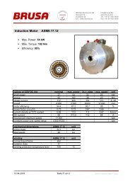
7.2 Anschluss des Gerätes<br />
Connecting the device<br />
HV – Connector<br />
Coolant<br />
Outlet<br />
Coolant Inlet<br />
Control –<br />
Connector<br />
LV(+) –<br />
Connector<br />
LV(-) –<br />
Connection<br />
• Mitgelieferte HV und LV – Leistungsstecker mit einem<br />
den Anforderungen (Stromstärke, Schirmung,...)<br />
entsprechendem Kabel konfektionieren. Auf Anfrage<br />
kann dies auch durch <strong>BRUSA</strong> durchgeführt werden.<br />
Die Länge des LV-Kabels zwischen 12V-Batterie und<br />
BSC624-12V darf 2m nicht überschreiten, damit der<br />
HV-Spannungsregler im Hochsetzstellbetrieb stabil<br />
bleibt.<br />
• Mitgelieferter Steuerstecker den Anforderungen<br />
(EMV, Umwelteinflüsse,...) entsprechend konfektionieren,<br />
wobei nur die tatsächlich verwendeten Pins<br />
verdrahtet werden müssen. Folgende Pins sind für<br />
den Betrieb zwingend notwendig:<br />
Nr.<br />
Abk. Funktion<br />
1 GND Masse (Bordnetz Minus, Klemme 31)<br />
2 AUX +12V (Bordnetz Plus, Klemme 30)<br />
3 EN Enable (Power ON, Klemme 15)<br />
9 CNL<br />
10 CNH<br />
CAN Low<br />
CAN High<br />
Der Pin EN muss über einen Schalter mit AUX<br />
verdrahtet werden (z.B.: im Fahrzeug über den<br />
Zündschlüssel mit dem Bordnetz).<br />
• Wasserkühlung (Schlauchdurchmesser innen 16mm)<br />
an den Kühlwasserstutzen des Gerätes anschliessen<br />
und sicherstellen, dass die Durchflussrate mindestens<br />
4l/min beträgt. Die Schlauchschellen müssen so<br />
positioniert werden wie auf dem Bild links abgebildet,<br />
damit es keine Kollision mit dem HV- und Steuerstecker<br />
gibt.<br />
• Leistungs- und Steuerstecker am Gerät anschliessen,<br />
wobei noch keine HV-Spannung anliegen darf.<br />
BSC624-12V_User_Manual_090615.doc 32 / 41<br />
• Assemble delivered HV and LV – power connectors<br />
according to the requirements (current,<br />
shielding,...) with an appropriate cable. Upon request<br />
this can also be done by <strong>BRUSA</strong>. The<br />
length of the LV-cable between 12V-battery and<br />
BSC624-12V must not exceed 2m, in order to ensure<br />
stable operation of the HV-voltage regulator<br />
in boost mode.<br />
• Assemble delivered control connector according<br />
to the requirements (EMC, environmental influence,…),<br />
whereas only the actual pins which are<br />
used have to be wired. Following pins are absolutely<br />
necessary for operation:<br />
No. Abbr. Function<br />
1 GND Ground (Auxiliary voltage minus, terminal<br />
31)<br />
2 AUX +12V (Auxiliary voltage plus, terminal<br />
30)<br />
3 EN Enable (Power ON, terminal 15)<br />
9 CNL<br />
10 CNH<br />
CAN low<br />
CAN high<br />
The pin EN has to be wired to AUX by a<br />
switch (e.g.: in the vehicle by the ignition key<br />
to the auxiliary supply).<br />
• Connect the water cooling (tube inner diameter<br />
16mm) at the cooling pipes of the device and ensure<br />
the flow rate is at least 4l/min. The hose<br />
clamp must be positioned according to the picture<br />
shown on the left in order to avoid collisions with<br />
the HV- and control connector.<br />
• Connect the power and control connectors to the<br />
device. Ensure that no high voltage is applied yet.
Betriebsanleitung BSC624-12V User’s manual BSC624-12V<br />
7.3 Bedienung des Gerätes<br />
Operation of the device<br />
7.4 Programmieren der Firmware<br />
Download the firmware<br />
7.4.1 PC - Systemanforderungen<br />
Requirements to the PC - system<br />
• Hochspannung allenfalls vorladen, bevor die Verbindungen<br />
mittels Schütze geschlossen werden.<br />
• Pin EN mit AUX verbinden (Zündschlüssel betätigen,<br />
Schalter schliessen).<br />
• Die CAN – Bedienoberfläche (CVI) kann optional<br />
auch durch <strong>BRUSA</strong> erstellt werden, falls das Gerät<br />
nicht ohnehin in ein vorhandenes CAN-<br />
Kommunikationsnetzwerk integriert wird. Ein solches<br />
Beispiel ist auf dem Bild links gezeigt, wobei die Inbetriebnahme<br />
dann folgendermassen abläuft:<br />
CAN – Bedienoberfläche starten und „Start“-<br />
Button drücken, um die Kommunikation mit dem<br />
Gerät zu ermöglichen. Mit dem Button „Run“ wie<br />
im Bild beschrieben wird die Leistungsstufe aktiviert.<br />
Die Kommunikation mit dem Gerät ist gewährleistet,<br />
wenn die Anzeige „Tx“ und „Rx“ blinkt.<br />
• Damit der Hauptregler seine Funktion erfüllen kann,<br />
muss sichergestellt sein, dass kein Begrenzungsregler<br />
im Eingriff ist.<br />
• Das Gerät kann in jedem Betriebszustand durch erneutes<br />
Betätigen des Button „Run“ und Deaktivieren<br />
des Pin EN abgeschaltet werden.<br />
• Auch das schlagartige Wegschalten der Hochspannung<br />
(Öffnen der Schütze) ist zulässig.<br />
• Beim BSC624-12V besteht die Möglichkeit die Firmware<br />
des Gerätes zu aktualisieren. Dies darf jedoch<br />
ausdrücklich nur nach Absprache mit <strong>BRUSA</strong> erfolgen.<br />
Die Firmware kann von einem gewöhnlichen PC<br />
über die RS232 – Schnittstelle programmiert werden.<br />
Nachfolgend sind die notwendigen Schritte genauer<br />
erläutert.<br />
• Betriebssystem Windows 95/98, Windows NT, Windows<br />
2000 und Windows XP (Installationsschritte<br />
können dann leicht von den Anweisungen abweichen).<br />
• Serielle Schnittstelle RS232<br />
BSC624-12V_User_Manual_090615.doc 33 / 41<br />
• Precharge the high voltage before closing the<br />
connections by contactors.<br />
• Connect the pin EN to AUX (activate ignition key,<br />
close switch).<br />
• The CAN – user interface (CVI) can be provided<br />
optionally by <strong>BRUSA</strong>, if the device will not be integrated<br />
in an anyway existing CAN-communication<br />
network. Such an example is shown on the picture<br />
on the left side, whereas the device has to be<br />
started as follows:<br />
Start the CAN – user interface and press the<br />
“Start”-button in order to allow communication<br />
with the device. With the button “Run” like described<br />
in the picture the power stage is activated.<br />
Communication with the device is ensured, if<br />
the displays “Tx” and “Rx” are blinking.<br />
• In order to allow the main regulator to fulfill its<br />
function ensure that no limiting regulator is active.<br />
• The device can be switched off in any operational<br />
condition by pressing again the button “Run” and<br />
deactivating the pin EN.<br />
• The sudden disconnection of the high voltage<br />
(open the contactors) is permissible as well.<br />
• The BSC624-12V has the possibility to be updated<br />
with a new firmware. This may only be done<br />
with agreement of <strong>BRUSA</strong>. The firmware can be<br />
downloaded from an ordinary PC over the RS232<br />
– interface. The necessary steps are described<br />
hereafter.<br />
• Operating system Windows 95/98, Windows NT,<br />
Windows 2000 und Windows XP (Installation<br />
steps may slightly be different from instructions).<br />
• Serial interface RS232
Betriebsanleitung BSC624-12V User’s manual BSC624-12V<br />
7.4.2 Einstellungen am Gerät und PC<br />
Configuration of the device and PC<br />
7.4.3 Installation der Programmier –<br />
Software<br />
Installation of the programming<br />
software<br />
• Verbinden Sie den Pin PRO (Pin 13 des Steuersteckers)<br />
mit dem Pin AUX (Pin 2 des Steuersteckers).<br />
• Stellen Sie eine Verbindung der RS232 – Schnittstelle<br />
am Gerät mit der seriellen Schnittstelle COM1 am<br />
Computer her.<br />
• Stellen Sie sicher, dass die RS232 – Schnittstelle am<br />
Computer von keiner anderen Anwendung belegt ist.<br />
• Versorgen Sie das Gerät entweder von Hochspannung<br />
oder vom Bordnetz.<br />
• Für detailierte Informationen bezüglich der Verdrahtung<br />
siehe unter 5.2 Steueranschluss.<br />
• Um eine neue Firmware programmieren zu können,<br />
muss das Hitachi „Flash Development Toolkit“ installiert<br />
werden. Dieses wird Ihnen auf Anfrage per Email<br />
zugeschickt. Nachfolgend ist die Installation genauer<br />
beschrieben.<br />
• Starten Sie das Setup und folgen Sie den Installationsanweisungen.<br />
BSC624-12V_User_Manual_090615.doc 34 / 41<br />
• „Hitachi/MCS“ aktivieren. • Activate “Hitachi/MCS”.<br />
• Connect the pin PRO (pin 13 of control connector)<br />
with the pin AUX (pin 2 of control connector).<br />
• Provide a connection of the RS232 – interface at<br />
the device with the serial interface COM1 at the<br />
computer.<br />
• Ensure that the RS232 – interface at the computer<br />
is not used by another application.<br />
• Supply the device either from high voltage or from<br />
the auxiliary supply.<br />
• For further information regarding the wiring refer<br />
to 5.2 control connector.<br />
• In order to download a new firmware the Hitachi<br />
“Flash Development Toolkit” has to be installed.<br />
This can be sent by email upon request. The installation<br />
is described hereafter.<br />
• Start the setup and follow the installation instructions.
Betriebsanleitung BSC624-12V User’s manual BSC624-12V<br />
BSC624-12V_User_Manual_090615.doc 35 / 41<br />
• “Install Kernel Binaries“ aktivieren. • Activate „Install Kernel Binaries“.<br />
• „SH7045F“ und „MCS” aktivieren. • Activate „SH7045F“ and „MCS“.
Betriebsanleitung BSC624-12V User’s manual BSC624-12V<br />
7.4.4 Anlegen eines Projektes<br />
Create a project<br />
• Beenden Sie die Installation durch Drücken des Button<br />
„Fertig stellen“.<br />
• Beim erstmaligen Starten des „Flash Development<br />
Toolkit“ muss nun ein neues Projekt angelegt werden.<br />
• „Create a new workspace“ aktivieren.<br />
BSC624-12V_User_Manual_090615.doc 36 / 41<br />
• Complete the installation.<br />
• When you first start the “Flash Development Toolkit”<br />
a new project has to be created.<br />
• Activate “Create new workspace”.
Betriebsanleitung BSC624-12V User’s manual BSC624-12V<br />
• Im Feld „Workspace Name“ geben Sie “SHC1” ein.<br />
• Im Feld „Location“ geben Sie den von Ihnen gewünschten<br />
Programmpfad ein.<br />
• Bestätigen Sie mit „Ja“. • Confirm with “Yes”.<br />
• Im Feld „Project Name“ geben Sie den gewünschten<br />
Projektnamen ein (z.B.: BSC624-12V).<br />
BSC624-12V_User_Manual_090615.doc 37 / 41<br />
• Type „SHC1“ in the field „Workspace Name“.<br />
• Select the corresponding program directory in the<br />
field “Location”.<br />
• Type an appropriate project name in the field “Project<br />
Name” (e.g.: BSC624-12V).
Betriebsanleitung BSC624-12V User’s manual BSC624-12V<br />
• Wählen Sie aus der Auswahlliste „SH/7045F“ aus. • Select from the list “SH/7045F”.<br />
• Wählen Sie den Port „Port 1“ und definieren die<br />
Übertragungsrate mit „57600“.<br />
• „BOOT Mode“ aktivieren.<br />
• Wählen sie die Verbindung „Direct Connection“.<br />
BSC624-12V_User_Manual_090615.doc 38 / 41<br />
• Select the port „Port 1“ and define the baud rate<br />
with „57600“.<br />
• Activate „BOOT Mode“.<br />
• Choose for the connection „Direct Connection“.
Betriebsanleitung BSC624-12V User’s manual BSC624-12V<br />
• „Interactive“ und „Standard“ aktivieren. • Activate „Interactive“ and „Standard“.<br />
• Wählen Sie im Menüpunkt „Tools” → “Customize” →<br />
“General“ folgende Einstellungen:<br />
Verifikation nach dem Programmieren? „No“.<br />
Resetieren des Gerätes beim Trennen? „Query“.<br />
„Reload last Workspace as startup“ aktivieren.<br />
BSC624-12V_User_Manual_090615.doc 39 / 41<br />
• Choose in the menu „Tools” → “Customize” →<br />
“General“ following configuration:<br />
• Verification after programming? „No“.<br />
• Reset the device when disconnecting? „Query“.<br />
• Activate „Reload last Workspace as startup“.
Betriebsanleitung BSC624-12V User’s manual BSC624-12V<br />
7.4.5 Download der Firmware<br />
Download of the firmware<br />
• Mit der rechten Maustaste auf den Ordner “Target Files”<br />
klicken.<br />
• Mit dem Befehl „Add Files to Project“ kann die Firmware<br />
(*.mot) aus dem entsprechendem Verzeichnis<br />
ausgewählt werden.<br />
• Mit der rechten Maustaste auf die gewünschte Firmware<br />
klicken und den Befehl “Download file to device”<br />
wählen.<br />
• Der Programmiervorgang wird nun gestartet.<br />
• Nach erfolgreichem Download der Firmware erscheint<br />
im unteren Fenster „Image successfully written<br />
to device“.<br />
• Damit ist der Programmiervorgang beendet und der<br />
Pin PRO kann wieder auf „Low“ gesetzt werden.<br />
• Das Gerät ist nun wieder betriebsbereit.<br />
• ACHTUNG: Der Download – Vorgang muss vollständig<br />
und fehlerfrei durchgeführt werden. Es muss immer<br />
die Meldung „Image successfully written to device“<br />
erscheinen.<br />
BSC624-12V_User_Manual_090615.doc 40 / 41<br />
• Click with the right mouse button on the folder<br />
“Target Files”.<br />
• With the command “Add Files to Project” the firmware<br />
(*.mot) can be selected from the corresponding<br />
directory.<br />
• Click with the right mouse button on the firmware<br />
which you wish to download and then choose the<br />
command „Download file to device“.<br />
• The programming process starts now.<br />
• After successful download of the firmware the<br />
message “Image successfully written to device”<br />
appears in the lower window.<br />
• Hence the download process is completed and<br />
the pin PRO can be set “low” again.<br />
• The device is now ready to operate again.<br />
• Attention: The download process has to be done<br />
completely and faultlessly. The message “Image<br />
successfully written to device” has always to appear.
Betriebsanleitung BSC624-12V User’s manual BSC624-12V<br />
8 Garantie<br />
Warranty<br />
• Wir gewähren eine Garantie von 24 Monaten ab<br />
dem Kaufdatum auf Material- und Verarbeitungsfehler.<br />
• Die Garantie erlischt bei unsachgemässer Behandlung<br />
des Gerätes.<br />
• Technische Änderungen sind jederzeit ohne Ankündigung<br />
möglich.<br />
• Wir weisen ausdrücklich darauf hin, dass mit diesem<br />
Gerät lebensgefährliche Spannungen verarbeitet<br />
werden können. Wir lehnen diesbezüglich jede<br />
Haftung ab.<br />
• Wir übernehmen keine Haftung durch Folgeschäden,<br />
die durch die Anwendung dieses Gerätes entstanden<br />
sind.<br />
BSC624-12V_User_Manual_090615.doc 41 / 41<br />
• We assure a warranty for a period of 24 month from<br />
the date of purchase for defects of material and by<br />
workmanship.<br />
• Improper use or handling of the product causes the<br />
warranty to be void.<br />
• Specifications are subject to change without notice.<br />
• Note that this device processes lethal voltages. We<br />
cannot accept any liability concerning this danger.<br />
• We cannot accept any liability for consequential<br />
damages which arose from the use of this device.