BRUSA Elektronik AG info@brusa
BRUSA Elektronik AG info@brusa
BRUSA Elektronik AG info@brusa

Erfolgreiche ePaper selbst erstellen
Machen Sie aus Ihren PDF Publikationen ein blätterbares Flipbook mit unserer einzigartigen Google optimierten e-Paper Software.
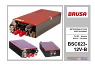
Betriebsanleitung BSC624-12V User’s manual BSC624-12V<br />
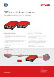
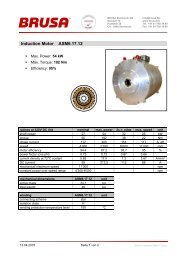
7.2 Anschluss des Gerätes<br />
Connecting the device<br />
HV – Connector<br />
Coolant<br />
Outlet<br />
Coolant Inlet<br />
Control –<br />
Connector<br />
LV(+) –<br />
Connector<br />
LV(-) –<br />
Connection<br />
• Mitgelieferte HV und LV – Leistungsstecker mit einem<br />
den Anforderungen (Stromstärke, Schirmung,...)<br />
entsprechendem Kabel konfektionieren. Auf Anfrage<br />
kann dies auch durch <strong>BRUSA</strong> durchgeführt werden.<br />
Die Länge des LV-Kabels zwischen 12V-Batterie und<br />
BSC624-12V darf 2m nicht überschreiten, damit der<br />
HV-Spannungsregler im Hochsetzstellbetrieb stabil<br />
bleibt.<br />
• Mitgelieferter Steuerstecker den Anforderungen<br />
(EMV, Umwelteinflüsse,...) entsprechend konfektionieren,<br />
wobei nur die tatsächlich verwendeten Pins<br />
verdrahtet werden müssen. Folgende Pins sind für<br />
den Betrieb zwingend notwendig:<br />
Nr.<br />
Abk. Funktion<br />
1 GND Masse (Bordnetz Minus, Klemme 31)<br />
2 AUX +12V (Bordnetz Plus, Klemme 30)<br />
3 EN Enable (Power ON, Klemme 15)<br />
9 CNL<br />
10 CNH<br />
CAN Low<br />
CAN High<br />
Der Pin EN muss über einen Schalter mit AUX<br />
verdrahtet werden (z.B.: im Fahrzeug über den<br />
Zündschlüssel mit dem Bordnetz).<br />
• Wasserkühlung (Schlauchdurchmesser innen 16mm)<br />
an den Kühlwasserstutzen des Gerätes anschliessen<br />
und sicherstellen, dass die Durchflussrate mindestens<br />
4l/min beträgt. Die Schlauchschellen müssen so<br />
positioniert werden wie auf dem Bild links abgebildet,<br />
damit es keine Kollision mit dem HV- und Steuerstecker<br />
gibt.<br />
• Leistungs- und Steuerstecker am Gerät anschliessen,<br />
wobei noch keine HV-Spannung anliegen darf.<br />
BSC624-12V_User_Manual_090615.doc 32 / 41<br />
• Assemble delivered HV and LV – power connectors<br />
according to the requirements (current,<br />
shielding,...) with an appropriate cable. Upon request<br />
this can also be done by <strong>BRUSA</strong>. The<br />
length of the LV-cable between 12V-battery and<br />
BSC624-12V must not exceed 2m, in order to ensure<br />
stable operation of the HV-voltage regulator<br />
in boost mode.<br />
• Assemble delivered control connector according<br />
to the requirements (EMC, environmental influence,…),<br />
whereas only the actual pins which are<br />
used have to be wired. Following pins are absolutely<br />
necessary for operation:<br />
No. Abbr. Function<br />
1 GND Ground (Auxiliary voltage minus, terminal<br />
31)<br />
2 AUX +12V (Auxiliary voltage plus, terminal<br />
30)<br />
3 EN Enable (Power ON, terminal 15)<br />
9 CNL<br />
10 CNH<br />
CAN low<br />
CAN high<br />
The pin EN has to be wired to AUX by a<br />
switch (e.g.: in the vehicle by the ignition key<br />
to the auxiliary supply).<br />
• Connect the water cooling (tube inner diameter<br />
16mm) at the cooling pipes of the device and ensure<br />
the flow rate is at least 4l/min. The hose<br />
clamp must be positioned according to the picture<br />
shown on the left in order to avoid collisions with<br />
the HV- and control connector.<br />
• Connect the power and control connectors to the<br />
device. Ensure that no high voltage is applied yet.