BRUSA Elektronik AG info@brusa
BRUSA Elektronik AG info@brusa
BRUSA Elektronik AG info@brusa

Erfolgreiche ePaper selbst erstellen
Machen Sie aus Ihren PDF Publikationen ein blätterbares Flipbook mit unserer einzigartigen Google optimierten e-Paper Software.
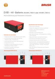
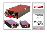
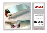
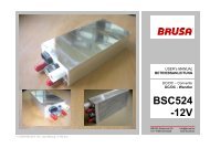
Betriebsanleitung BSC624-12V User’s manual BSC624-12V<br />
• Um bei Bedarf einen autarken Betrieb des Geräts zu<br />
gewährleisten, ist eine 10.7V/0.1A-Versorgung implementiert.<br />
Auf diese Weise kann beispielsweise EN<br />
(3) durch eine Verbindung mit AUX (2) im kundenseitigen<br />
Stecker aktiviert werden, sodass das Gerät immer<br />
eingeschaltet ist.<br />
• Die 12.5V/2.5A-Versorgung ist ebenfalls mit der –<br />
auch im Hoch-/Tiefsetzsteller eingesetzten – Autokommutierung-Topologie<br />
realisiert. Diese Speisung<br />
ist galvanisch vom Hochspannungskreis getrennt und<br />
funktioniert zudem ohne Optokoppler.<br />
• Im Hochsetzstellbetrieb werden die Treiber beim<br />
Hochstarten zu Beginn von AUX(2) versorgt.<br />
• Sämtliche Versorgungsschaltkreise sind kurzschlussfest.<br />
• Die Signalmasse (GND (1)) ist von der Leistungsmasse<br />
(LV-) galvanisch getrennt, um Potentialverschleppungen<br />
bzw. Masseschleifen zu verhindern.<br />
BSC624-12V_User_Manual_090615.doc 21 / 41<br />
• A 10.7V/0.1A-supply is implemented, in order to<br />
ensure an autarkic operation of the device, if required.<br />
Thus, EN (3) for instance could be activated<br />
by a connection to AUX (2) in the customerside<br />
connector, so that the device will be permanently<br />
switched on.<br />
• The 12.5V/2.5A-supply is realized again with the –<br />
also in the buck/boost converter used – Auto-<br />
Commutation-topology. This supply is galvanically<br />
isolated from the high voltage circuit and furthermore<br />
functions without an optocoupler.<br />
• In boost mode the drivers will be supplied from<br />
AUX (2) in the very beginning of the start-up.<br />
• All supply circuits are short-circuit-proof.<br />
• The signal ground (GND (1)) is galvanically isolated<br />
from the power ground (LV-), in order to<br />
avoid accidental energisation, resp. ground loops.