BRUSA Elektronik AG info@brusa
BRUSA Elektronik AG info@brusa
BRUSA Elektronik AG info@brusa

Sie wollen auch ein ePaper? Erhöhen Sie die Reichweite Ihrer Titel.
YUMPU macht aus Druck-PDFs automatisch weboptimierte ePaper, die Google liebt.
Betriebsanleitung BSC624-12V User’s manual BSC624-12V<br />
5.2.2.5 PG1 – PG3 (Analoge Masse, Analog<br />
Ground), Pins 8, 14, 15<br />
Interne Beschaltung<br />
Internal Circuit<br />
PG1 – PG3 (8, 14, 15)<br />
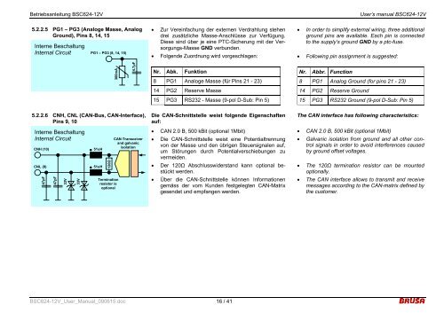
5.2.2.6 CNH, CNL (CAN-Bus, CAN-Interface),<br />
Pins 9, 10<br />
Interne Beschaltung<br />
Internal Circuit<br />
CNH (10)<br />
CNL (9)<br />
47pF<br />
47pF<br />
33V<br />
33V<br />
51uH<br />
51uH<br />
120Ω<br />
300mA<br />
Termination<br />
resistor is<br />
optional<br />
4.7µF<br />
CAN-Transceiver<br />
and galvanic<br />
isolation<br />
• Zur Vereinfachung der externen Verdrahtung stehen<br />
drei zusätzliche Masse-Anschlüsse zur Verfügung.<br />
Diese sind über je eine PTC-Sicherung mit der Versorgungs-Masse<br />
GND verbunden.<br />
• Folgende Zuordnung wird vorgeschlagen:<br />
Nr.<br />
Abk. Funktion<br />
8 PG1 Analoge Masse (für Pins 21 - 23)<br />
14<br />
PG2 Reserve Masse<br />
15 PG3 RS232 - Masse (9-pol D-Sub: Pin 5)<br />
Die CAN-Schnittstelle weist folgende Eigenschaften<br />
auf:<br />
• CAN 2.0 B, 500 kBit (optional 1Mbit)<br />
• Die CAN-Schnittstelle weist eine Potentialtrennung<br />
von der Masse und den übrigen Steuersignalen auf,<br />
um Störungen durch Potentialverschiebungen zu<br />
vermeiden.<br />
• Der 120Ω Abschlusswiderstand kann optional bestückt<br />
werden.<br />
• Über die CAN-Schnittstelle können Informationen<br />
gemäss der vom Kunden festgelegten CAN-Matrix<br />
gesendet und empfangen werden.<br />
BSC624-12V_User_Manual_090615.doc 16 / 41<br />
• In order to simplify external wiring, three additional<br />
ground pins are available. Each pin is connected<br />
to the supply’s ground GND by a ptc-fuse.<br />
• Following pin assignment is suggested:<br />
Nr.<br />
Abbr. Function<br />
8 PG1 Analog Ground (for pins 21 - 23)<br />
14<br />
PG2 Reserve Ground<br />
15 PG3 RS232 Ground (9-pol D-Sub: Pin 5)<br />
The CAN interface has following characteristics:<br />
• CAN 2.0 B, 500 kBit (optional 1Mbit)<br />
• Galvanic isolation from ground and all other control<br />
signals in order to avoid interferences caused<br />
by ground offset voltages.<br />
• The 120Ω termination resistor can be mounted<br />
optionally.<br />
• The CAN interface allows to transmit and receive<br />
messages according to the CAN-matrix defined by<br />
the customer.