
Erfolgreiche ePaper selbst erstellen
Machen Sie aus Ihren PDF Publikationen ein blätterbares Flipbook mit unserer einzigartigen Google optimierten e-Paper Software.
Betriebsanleitung <strong>BSC524</strong>-<strong>12V</strong> User’s manual <strong>BSC524</strong>-<strong>12V</strong><br />
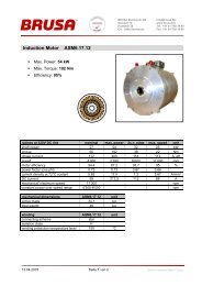
5.2.2.9 DI0 – DI2 (Digitale Eingänge, Digital<br />
Inputs), Pins 16 – 18<br />
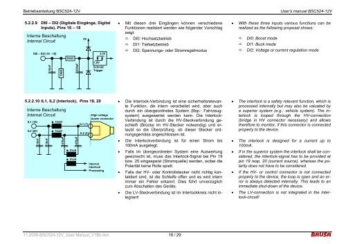
Interne Beschaltung<br />
Internal Circuit<br />
DI0 – DI2 (16 - 18)<br />
10nF<br />
10kΩ<br />
22kΩ<br />
220pF<br />
5V<br />
1,0V<br />
3,3V<br />
Schmitt<br />
Trigger<br />
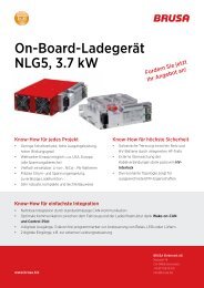
5.2.2.10 IL1, IL2 (Interlock), Pins 19, 20<br />
Interne Beschaltung<br />
Internal Circuit<br />
IL1 (19)<br />
IL2 (20)<br />
10nF<br />
10nF<br />
12mH<br />
12mH<br />
470pF<br />
470pF<br />
51uH<br />
51uH<br />
IL1 (1)<br />
IL2 (2)<br />
High voltage<br />
power connector<br />
Internal<br />
Interlock<br />
Processing<br />
• Mit diesen drei Eingängen können verschiedene<br />
Funktionen realisiert werden wie folgender Vorschlag<br />
zeigt:<br />
DI0: Hochsetzbetrieb<br />
DI1: Tiefsetzbetrieb<br />
DI2: Spannungs- oder Stromregelmodus<br />
• Die Interlock-Verbindung ist eine sicherheitsrelevante<br />
Funktion, die intern verarbeitet wird, aber auch<br />
durch ein übergeordnetes System (Bsp.: Fahrzeugsystem)<br />
ausgewertet werden kann. Die Interlock-<br />
Verbindung ist durch die HV-Steckverbindung geschleift<br />
(Brücke im HV-Stecker notwendig) und erlaubt<br />
so die Überprüfung, ob dieser Stecker ordnungsgemäss<br />
angeschlossen ist.<br />
• Die Interlockverbindung ist für einen Strom bis<br />
100mA ausgelegt.<br />
• Falls im übergeordneten System eine Auswertung<br />
gewünscht ist, muss das Interlock-Signal bei Pin 19<br />
bzw. 20 eingespeist (Stromquelle) werden, wobei die<br />
Polarität keine Rolle spielt.<br />
• Falls der HV- oder Kontrollstecker nicht richtig kontaktiert<br />
sind, ist die Schleife offen und es wird intern<br />
immer ein Fehler erkannt. Dies führt unverzüglich<br />
zum Abschalten des Geräts.<br />
• Die LV-Steckverbindung ist im Interlockkreis nicht integriert!<br />
11.2006-<strong>BSC524</strong>-<strong>12V</strong>_User Manual_V18b.doc 18 / 29<br />
• With these three inputs various functions can be<br />
realized as the following proposal shows:<br />
DI0: Boost mode<br />
DI1: Buck mode<br />
DI2: Voltage or current regulation mode<br />
• The interlock is a safety relevant function, which is<br />
processed internally but may also be valuated by<br />
a superior system (e.g.: vehicle system). The interlock<br />
is looped through the HV-connection<br />
(bridge in HV connector necessary) and allows<br />
therefore to monitor, if this connector is connected<br />
properly to the device.<br />
• The interlock is designed for a current up to<br />
100mA.<br />
• If in the superior system the interlock shall be considered,<br />
the interlock-signal has to be provided at<br />
pin 19 resp. 20 (current source), whereas the polarity<br />
does not have to be considered.<br />
• If the HV- or control connector is not connected<br />
properly to the device, the loop is open and an error<br />
is always detected internally. This leads to an<br />
immediate shut-down of the device.<br />
• The LV-connection is not integrated in the interlock-circuit!