ekey home integra Bedienungsanleitung Steuereinheit ... - Gueller.ch
ekey home integra Bedienungsanleitung Steuereinheit ... - Gueller.ch
ekey home integra Bedienungsanleitung Steuereinheit ... - Gueller.ch

Sie wollen auch ein ePaper? Erhöhen Sie die Reichweite Ihrer Titel.
YUMPU macht aus Druck-PDFs automatisch weboptimierte ePaper, die Google liebt.
BEDIENUNGSANLEITUNG<br />
OPERATING INSTRUCTIONS<br />
<strong>ekey</strong> ® TOCA<strong>home</strong> <strong>integra</strong><br />
<strong>ekey</strong> ® TOCA<strong>home</strong> 2 <strong>integra</strong><br />
<strong>ekey</strong> ® TOCA<strong>home</strong> pc <strong>integra</strong><br />
Zutrittsystem mit Fingerscan<br />
Fingerscan Access Control System<br />
®
VORWORT<br />
Wir gratulieren Ihnen zum Erwerb dieses High Te<strong>ch</strong> Fingerscan Systems <strong>ekey</strong> ®<br />
TOCA<strong>home</strong>. Ihr System ist mit hö<strong>ch</strong>ster Erkennungspräzision und hö<strong>ch</strong>ster Qualität<br />
gefertigt. Sie werden ein neues Gefühl erleben, wenn Sie si<strong>ch</strong> im Urlaub ni<strong>ch</strong>t über Ihren<br />
S<strong>ch</strong>lüssel Gedanken ma<strong>ch</strong>en müssen.<br />
Wir wüns<strong>ch</strong>en Ihnen viel Freude mit Ihrem Produkt.<br />
Besu<strong>ch</strong>en Sie die Webseite von <strong>ekey</strong> biometric systems GmbH unter:<br />
www.<strong>ekey</strong>.net<br />
Dort finden Sie stets die aktuellste Version dieses Dokuments, sowie weitere<br />
zusätzli<strong>ch</strong>e Informationen über dieses und andere Produkte von <strong>ekey</strong> biometric<br />
systems.<br />
Sollten Sie no<strong>ch</strong> offene Fragen haben, so wenden Sie si<strong>ch</strong> bitte an unseren<br />
Support unter der Nummer +43 732 6910 4552. Unser gesamtes Team steht<br />
Ihnen gerne für weitere Informationen zur Verfügung.<br />
2
1. PRODUKTÜBERSICHT 4<br />
2. LIEFERUMFANG 4<br />
3. BETRIEB 5<br />
3.1 BEDIENUNG DER TASTEN 5<br />
3.2 ERSTE INBETRIEBNAHME:<br />
KOPPELUNG ZWISCHEN STEUEREINHEIT UND FINGERSCANNER 5<br />
3.3 ÜBERSICHT PROGRAMMIERMENÜ DER STEUEREINHEIT: 6<br />
3.4 AUFNAHME EINES FINGERS ÜBER DEN SENSOR (SIEHE SEITE 11) 7<br />
3.5 EINLERNEN EINES FINGERS IN DAS SYSTEM 7<br />
3.6 AUFNAHME DES FINGERS 8<br />
3.7 LÖSCHEN EINES BENUTZERS 8<br />
3.8 EINSTELLEN EINES NEUEN SICHERHEITSCODES 9<br />
3.9 RÜCKSETZEN AUF WERKSEINSTELLUNG 9<br />
4. BEDIENUNG DES FINGERSCANNERS 10<br />
5. FEHLERBESCHREIBUNG 12<br />
6. TECHNISCHE DATEN 14<br />
6.1 STECKERBELEGUNG DER STEUEREINHEIT INTEGRA 15<br />
6.2 ABMESSUNGEN DER STEUEREINHEIT INTEGRA 16<br />
6.3 ABMESSUNGEN DES FINGERSCANNER INTEGRA 17<br />
7. MONTAGE UND INSTALLATION 18<br />
7.1 AUSFRÄSUNG STEUEREINHEIT 18<br />
7.2 AUSFRÄSUNG FINGERSCANNER 19<br />
7.3 MONTAGE DER STEUEREINHEIT 20<br />
7.4 MONTAGE DES FINGERSCANNERS 21<br />
7.5 MONTAGEHÖHE FÜR STEUEREINHEIT UND FINGERSCANNER 22<br />
7.6 MONTAGE DES DEKORELEMENTS 23<br />
7.7 DEMONTAGE DES DEKORELEMENTS 23<br />
8. VERDRAHTUNGSBEISPIELE 24<br />
8.1 MINIMALINSTALLATION 24<br />
8.2 INSTALLATION MIT EXTERNEM SCHALTER UND VERBRAUCHER 25<br />
8.3 INSTALLATION MIT AUFPUTZ STEUEREINHEIT 26<br />
9. HERSTELLERGARANTIE 27<br />
3
1. PRODUKTÜBERSICHT<br />
Ihr Produkt ist ein, in die Tür bzw. Türrahmen voll integriertes biometris<strong>ch</strong>es<br />
Zutrittsystem, das mit einem Fingerscanner ausgestattet ist. Dieser Scanner liest<br />
spezielle Merkmale ihrer Fingerlinien und verwendet diese zur Erkennung des<br />
Zutrittbere<strong>ch</strong>tigten. Jeder Ihrer Finger weist unters<strong>ch</strong>iedli<strong>ch</strong>e Erkennungsmerkmale auf<br />
und unters<strong>ch</strong>eidet si<strong>ch</strong> ebenfalls von den Fingern anderer Personen.<br />
Die <strong>ekey</strong> ® TOCA<strong>home</strong> <strong>integra</strong> <strong>Steuereinheit</strong> ist dafür vorgesehen, direkt ein elektris<strong>ch</strong>es<br />
Motors<strong>ch</strong>loss anzusteuern. Vorzugsweise ist dies bei Verkabelung in der Tür das Relais 1.<br />
Mittels eines externen Eingangs lässt si<strong>ch</strong> Relais 1 über einen externen Taster<br />
fernbedienen und eine Fernöffnung, beispielsweise über eine Spre<strong>ch</strong>anlage oder<br />
ähnli<strong>ch</strong>es, realisieren. Voraussetzung dafür ist ein potentialfreier S<strong>ch</strong>alter.<br />
2. LIEFERUMFANG<br />
Die <strong>ekey</strong> ® TOCA<strong>home</strong> <strong>integra</strong> <strong>Steuereinheit</strong> und der <strong>ekey</strong> ® TOCA<strong>home</strong> <strong>integra</strong><br />
Fingerscanner werden bereits fertig montiert, anges<strong>ch</strong>lossen und betriebsbereit mit der<br />
Türe geliefert.<br />
Es ist kein zusätzli<strong>ch</strong>er Installations- und Montageaufwand erforderli<strong>ch</strong>.<br />
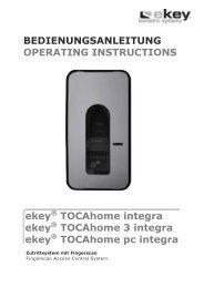
<strong>ekey</strong> ® TOCA<strong>home</strong> <strong>integra</strong> Fingerscanner<br />
4<br />
Statusanzeige<br />
Anzeige<br />
Funktionsanzeige<br />
Sensor<br />
Bedientasten<br />
<strong>ekey</strong> ® TOCA<strong>home</strong> <strong>integra</strong> <strong>Steuereinheit</strong>
3. BETRIEB<br />
3.1 BEDIENUNG DER TASTEN<br />
Die Bedienung erfolgt über die 4 Tasten:<br />
OK Taste: dient zum Einstieg in das Menü und zum<br />
Bestätigen der Eingabe.<br />
< und > -Tasten: dienen zum Umstellen der Werte in der Anzeige<br />
bzw. zum Navigieren im Programmiermenü.<br />
(s. Abb. Kapitel 3.3)<br />
ESC Taste (X): dient zum Abbre<strong>ch</strong>en der aktuellen Eingabe.<br />
PROGRAMM-, MENÜFUNKTION UND DISPLAYANZEIGE<br />
Normalbetrieb (blinkender Punkt) .<br />
Benutzer anlegen (enroll user) Eu<br />
Benutzer lös<strong>ch</strong>en (delete user) du<br />
Si<strong>ch</strong>erheitscode einstellen (Security code) Sc<br />
Reset auf Werkseinstellungen rr<br />
(Lös<strong>ch</strong>en aller Benutzereinstellungen und Daten)<br />
3.2 ERSTE INBETRIEBNAHME:<br />
KOPPELUNG ZWISCHEN STEUEREINHEIT UND FINGERSCANNER<br />
Beim Ans<strong>ch</strong>luss der Geräte an die Stromversorgung wird auf dem Display der<br />
<strong>Steuereinheit</strong> rückwärts gezählt, bis die Verbindung zum Fingerscanner hergestellt ist.<br />
Dana<strong>ch</strong> ers<strong>ch</strong>einen zwei rote Punkte. Während dieser Zeit leu<strong>ch</strong>tet die Statusanzeige am<br />
Fingerscanner rot. Na<strong>ch</strong>dem der Startvorgang abges<strong>ch</strong>lossen ist, beginnt die<br />
Statusanzeige orange zu blinken. Nun kann die Initialisierung gestartet werden.<br />
Betätigen Sie bitte die OK–Taste und im Ans<strong>ch</strong>luss die ESC-Taste. Am Display ers<strong>ch</strong>eint<br />
„EF“ für „Enroll Finger“. Nun kann ein bereits aufgenommener Finger über den Sensor<br />
gezogen werden und der Initialisierungsvorgang wird gestartet, ohne dass dabei Daten<br />
gelös<strong>ch</strong>t werden.<br />
Sind no<strong>ch</strong> keine Finger aufgenommen (Neuinstallation), so kann mit der ESC-Taste der<br />
Initialisierungsvorgang abges<strong>ch</strong>lossen werden.<br />
Der Initialisierungsvorgang läuft vollautomatis<strong>ch</strong> ab, dabei werden die Geräte aneinander<br />
gekoppelt. Diese Koppelung dient dazu, bei einem missbräu<strong>ch</strong>li<strong>ch</strong>en Taus<strong>ch</strong> des<br />
Fingerscanners, den Zutritt für Unbefugte zu verhindern.<br />
Na<strong>ch</strong> der Initialisierung signalisiert der blinkende Punkt am Display der <strong>Steuereinheit</strong> den<br />
Normalbetrieb. Der Security Code ist auf den Standardwert 99 eingestellt. Bitte ändern<br />
Sie diesen sobald wie mögli<strong>ch</strong> auf einen zweistelligen Security Code Ihrer Wahl.<br />
5
3.3 ÜBERSICHT PROGRAMMIERMENÜ DER STEUEREINHEIT:<br />
Im Menü na<strong>ch</strong> unten gelangen Sie jeweils mit der Taste OK. Na<strong>ch</strong> Oben gelangen Sie mit<br />
der Taste ESC. Geblättert bzw. eine Auswahl getroffen wird mit den Tasten Links < und<br />
Re<strong>ch</strong>ts >.<br />
6<br />
Eu<br />
Aufnahme<br />
neuer Finger<br />
1…99<br />
Benutzer-Nr.<br />
auswählen<br />
F1,…F9,F0<br />
Finger-Nr.<br />
auswählen<br />
01…02<br />
Relais auswählen<br />
Siehe<br />
Abs<strong>ch</strong>nitt 3.5<br />
du<br />
Benutzer<br />
lös<strong>ch</strong>en<br />
1…99<br />
Benutzer-Nr.<br />
auswählen<br />
Siehe<br />
Abs<strong>ch</strong>nitt 3.7<br />
. blinkender Punkt<br />
Normalbetrieb<br />
0…99<br />
Eingabe Si<strong>ch</strong>erheitscode<br />
Sc<br />
Einstellen<br />
Si<strong>ch</strong>erheitscode<br />
0…99<br />
Eingabe neuer<br />
Si<strong>ch</strong>erheitscode<br />
Siehe<br />
Abs<strong>ch</strong>nitt 3.8<br />
rr<br />
Rücksetzen auf<br />
Werkseinstellung<br />
0…99<br />
Eingabe<br />
Si<strong>ch</strong>erheitscode<br />
Siehe<br />
Abs<strong>ch</strong>nitt 3.9
3.4 AUFNAHME EINES FINGERS ÜBER DEN SENSOR (SIEHE SEITE 11)<br />
Es ist wi<strong>ch</strong>tig, dass Sie den Finger korrekt über den Sensor ziehen.<br />
!<br />
Die besten Ergebnisse erzielen Sie dur<strong>ch</strong> die Verwendung des mittleren<br />
Fingers und glei<strong>ch</strong>zeitigem Ausstrecken des Ring- und Zeigefingers.<br />
Ziehen Sie bitte den gewüns<strong>ch</strong>ten Finger ab dem vorderen Gelenk mögli<strong>ch</strong>st<br />
ganzflä<strong>ch</strong>ig über den Sensor. Je größer die eingelesene Fingerflä<strong>ch</strong>e ist, desto besser<br />
wird ihr Finger vom Gerät wiedererkannt.<br />
Um eine mögli<strong>ch</strong>st gute Erkennungsleistung zu erhalten ziehen Sie bitte den Finger<br />
immer in glei<strong>ch</strong>er Weise als beim Einspei<strong>ch</strong>ervorgang über den Sensor.<br />
Der Sensor befindet si<strong>ch</strong> in der Mitte der Fingerführung (grauer Streifen, siehe Abbildung<br />
auf Seite 4). Finger zart, mit wenig Druck mit glei<strong>ch</strong>mäßiger, mittlerer<br />
Ges<strong>ch</strong>windigkeit über den Sensor ziehen.<br />
Manuell tätige Personen sollen besonders auf die Abnutzung der Fingerlinien a<strong>ch</strong>ten, d.h.<br />
Re<strong>ch</strong>tshänder sollten in diesem Fall Finger der linken Hand einspei<strong>ch</strong>ern.<br />
Sollten Sie bei Ihren Fingern erkennen, dass die Fingerlinien mit dem freien Auge<br />
s<strong>ch</strong>le<strong>ch</strong>t erkennbar sind, so verwenden Sie bitte die Finger bei denen die Fingerlinien am<br />
s<strong>ch</strong>önsten ausgeprägt sind.<br />
ACHTUNG:<br />
Bitte versu<strong>ch</strong>en Sie eine größtmögli<strong>ch</strong>e Flä<strong>ch</strong>e Ihres Fingers ab dem vorderen Gelenk<br />
mit wenig Druck über den Sensor zu ziehen. Damit errei<strong>ch</strong>en Sie die hö<strong>ch</strong>ste<br />
Erkennungsleistung.<br />
3.5 EINLERNEN EINES FINGERS IN DAS SYSTEM<br />
Es können maximal 99 Finger eingelernt werden.<br />
3.5.1 EINGABE DES SICHERHEITSCODES<br />
� Drücken Sie die OK–Taste auf der <strong>Steuereinheit</strong>.<br />
� Geben Sie mit den < und >-Tasten die linke Ziffer des Securitycodes ein<br />
(Werkseinstellung ist 9)<br />
� Drücken Sie die OK–Taste.<br />
� Geben Sie mit den < und >-Tasten die re<strong>ch</strong>te Ziffer des Securitycodes ein<br />
(Werkseinstellung ist 9)<br />
� Drücken Sie die OK –Taste.<br />
� In der Anzeige leu<strong>ch</strong>tet „Eu“ (Enroll user)<br />
(„Enroll“ = „registrieren“)<br />
3.5.2 VERGABE DER BERECHTIGUNG<br />
� Wenn in der Anzeige „Eu“ leu<strong>ch</strong>tet, drücken Sie die OK–Taste.<br />
� Auswahl des Benutzers: In der Anzeige steht „1“ Sollte die Benutzernummer<br />
s<strong>ch</strong>on in Verwendung sein, so wird dies mit einem leu<strong>ch</strong>tenden Punkt neben der<br />
7
8<br />
Zahl signalisiert. Beispiel: „1.“ Stellen Sie mit den < und >-Tasten die<br />
gewüns<strong>ch</strong>te Benutzernummer ein.<br />
� Drücken Sie die OK–Taste.<br />
� Auswahl des Fingers: In der Anzeige ers<strong>ch</strong>eint „F1“ für Finger 1. Beginnen Sie<br />
bitte an der linken Hand mit dem kleinen Finger zu zählen. Der re<strong>ch</strong>te kleine<br />
Finger hat die Nummer 10 (= Einstellung „F0“ in der Anzeige). Ist eine<br />
Fingernummer s<strong>ch</strong>on belegt, so wird dies wiederum mit einem Punkt neben der<br />
Zahl signalisiert. Stellen Sie beispielsweise für den re<strong>ch</strong>ten Zeigefinger „F7“ ein.<br />
� Drücken Sie die OK–Taste.<br />
� Sie können nun festlegen, wel<strong>ch</strong>es Relais mit dem zuvor gewählten Finger<br />
angesteuert werden soll.<br />
Auswahl des Relais: Am Display signalisiert die Anzeige „o1“, dass derzeit das<br />
erste Relais (Motors<strong>ch</strong>loss) ausgewählt ist (Standardeinstellung). Stellen Sie mit<br />
den < und >-Tasten das gewüns<strong>ch</strong>te anzusteuernde Relais ein und drücken<br />
Sie die OK–Taste. Nun ers<strong>ch</strong>eint au<strong>ch</strong> in diesem Fall die Anzeige „EF“.<br />
Mögli<strong>ch</strong>keiten: „o1“ Relais 1 (typ. Motors<strong>ch</strong>loss)<br />
„o2“ Relais 2 (nur bei <strong>ekey</strong> ® TOCA<strong>home</strong> 2 <strong>integra</strong>)<br />
3.6 AUFNAHME DES FINGERS<br />
� Na<strong>ch</strong> Ers<strong>ch</strong>einen der Anzeige „EF“ haben Sie nun 60 Sekunden Zeit, Ihren Finger<br />
ab dem vorderen Gelenk über den Sensor zu ziehen.<br />
� Die Aufnahme sollte in der in Abs<strong>ch</strong>nitt 3.4 bes<strong>ch</strong>riebenen Art und Weise<br />
ges<strong>ch</strong>ehen.<br />
� Der Fingerscanner besitzt eine Statusanzeige (LED), die in drei vers<strong>ch</strong>iedenen<br />
Farben den Zustand signalisiert:<br />
Rot: Der Finger konnte ni<strong>ch</strong>t erfolgrei<strong>ch</strong> eingescannt werden<br />
bitte den Ziehvorgang wiederholen!<br />
Orange: Betriebsmodus Enrollment. Das Gerät wartet auf einen<br />
zu spei<strong>ch</strong>ernden Finger.<br />
Grün: erfolgrei<strong>ch</strong>er Scan<br />
3.7 LÖSCHEN EINES BENUTZERS<br />
3.7.1 EINGABE DES SICHERHEITSCODES<br />
� Drücken Sie die OK–Taste in der <strong>Steuereinheit</strong>.<br />
� Geben Sie mit den < und >-Tasten die linke Ziffer des Securitycodes ein<br />
(Werkseinstellung ist 9)<br />
� Drücken Sie die OK–Taste.<br />
� Geben Sie mit den < und >-Tasten die re<strong>ch</strong>te Ziffer des Securitycodes ein<br />
(Werkseinstellung ist 9)<br />
� Drücken Sie die OK–Taste.<br />
� In der Anzeige leu<strong>ch</strong>tet „Eu“ (Enroll user)<br />
3.7.2 AUSWAHL UND LÖSCHEN DES BENUTZERS<br />
� Drücken Sie so oft auf die >-Taste bis „du“ (delete user) angezeigt wird.<br />
� Drücken Sie die OK–Taste.
� Wählen Sie mit den < und >-Tasten die gewüns<strong>ch</strong>te Benutzernummer, die aus<br />
dem System gelös<strong>ch</strong>t werden soll.<br />
� Drücken Sie die OK–Taste.<br />
� „OK“ leu<strong>ch</strong>tet in der Anzeige kurz auf. Das Gerät geht dana<strong>ch</strong> in den<br />
Normalbetrieb zurück.<br />
3.8 EINSTELLEN EINES NEUEN SICHERHEITSCODES<br />
Bea<strong>ch</strong>ten Sie bitte, dass ohne den neu eingestellten Si<strong>ch</strong>erheitscode das Gerät ni<strong>ch</strong>t<br />
mehr bedient werden kann.<br />
Na<strong>ch</strong> dreimaliger Fals<strong>ch</strong>eingabe des Si<strong>ch</strong>erheitscodes wird das Gerät für 30 Minuten<br />
gesperrt.<br />
3.8.1 EINGABE DES BISHERIGEN SICHERHEITSCODES<br />
� Drücken Sie die OK–Taste in der <strong>Steuereinheit</strong><br />
� Geben Sie mit den < und >-Tasten die linke Ziffer des Securitycodes ein<br />
(Werkseinstellung ist 9)<br />
� Drücken Sie die OK–Taste<br />
� Geben Sie mit den < und >-Tasten die re<strong>ch</strong>te Ziffer des Securitycodes ein<br />
(Werkseinstellung ist 9)<br />
� Drücken Sie die OK–Taste<br />
� In der Anzeige leu<strong>ch</strong>tet „Eu“ (Enroll user)<br />
3.8.2 DURCHFÜHRUNG DER NEUEINSTELLUNG<br />
� Drücken Sie so oft auf die >-Taste bis „Sc“ angezeigt wird<br />
� Drücken Sie die OK–Taste<br />
� Geben Sie mit den < und >-Tasten die linke Ziffer des neuen Securitycodes ein<br />
� Drücken Sie die OK–Taste<br />
� Geben Sie mit den < und >-Tasten die re<strong>ch</strong>te Ziffer des neuen Securitycodes<br />
ein<br />
� Drücken Sie die OK–Taste<br />
� Es ers<strong>ch</strong>eint kurz die Anzeige „Ok“. Das Gerät geht dana<strong>ch</strong> in den Normalbetrieb<br />
zurück<br />
3.9 RÜCKSETZEN AUF WERKSEINSTELLUNG<br />
Beim Rücksetzen auf die Werkseinstellung werden alle Daten im Spei<strong>ch</strong>er gelös<strong>ch</strong>t. Der<br />
Securitycode wird auf den Standardwert 99 gesetzt, die <strong>Steuereinheit</strong> und der<br />
Fingerscanner verlieren ihre Kopplung.<br />
3.9.1 EINGABE DES SICHERHEITSCODES<br />
� Drücken Sie die OK–Taste in der <strong>Steuereinheit</strong><br />
� Geben Sie mit den < und >-Tasten die linke Ziffer des Securitycodes ein<br />
(Werkseinstellung ist 9)<br />
� Drücken Sie die OK–Taste<br />
� Geben Sie mit den < und >-Tasten die re<strong>ch</strong>te Ziffer des Securitycodes ein<br />
(Werkseinstellung ist 9)<br />
� Drücken Sie die OK–Taste.<br />
� In der Anzeige leu<strong>ch</strong>tet „Eu“ (Enroll user)<br />
9
3.9.2 DURCHFÜHRUNG DER RÜCKSTELLUNG<br />
� Drücken Sie so oft auf die >-Taste bis „rr“ angezeigt wird<br />
� Drücken Sie die OK–Taste<br />
� Geben Sie mit den < und >-Tasten die linke Ziffer des Securitycodes ein<br />
(Werkseinstellung ist 9)<br />
� Drücken Sie die OK–Taste<br />
� Geben Sie mit den < und >-Tasten die re<strong>ch</strong>te Ziffer des Securitycodes ein<br />
(Werkseinstellung ist 9)<br />
� Drücken Sie die OK–Taste<br />
� Es ers<strong>ch</strong>eint kurz „OK“ im Display, dana<strong>ch</strong> zwei rote Punkte. Die Fingerscanner<br />
blinkt orange. Das Gerät befindet si<strong>ch</strong> im Auslieferungszustand.<br />
4. BEDIENUNG DES FINGERSCANNERS<br />
Die Korrekte Bedienung des Fingerscanners ist ihre Erfolgsgarantie für die Funktion des<br />
Produktes.<br />
Bitte verwenden Sie die Finger mit den Ihrer Meinung na<strong>ch</strong> s<strong>ch</strong>önsten Fingerlinien.<br />
Speziell bei s<strong>ch</strong>wa<strong>ch</strong>ausgeprägten Fingerlinien sollten sie den Druck beim Ziehen über<br />
den Sensor so weit wie mögli<strong>ch</strong> vermindern um die ohnehin fla<strong>ch</strong>en Fingerlinien ni<strong>ch</strong>t zu<br />
quets<strong>ch</strong>en.<br />
Der Fingerscanner ist mit einem vollautomatis<strong>ch</strong>em Lernsystem ausgestattet um die<br />
Erkennungsleistung über lange Zeit zu gewähren.<br />
Zur Optimierung der Fingererkennung ziehen Sie am besten jeden Finger mindestens 5<br />
mal über den Sensor. Sollten Sie Ablehnungen haben, so wiederholen Sie bitte diesen<br />
Vorgang.<br />
Sollten Sie keine ausrei<strong>ch</strong>ende Fingererkennungsleistung haben versu<strong>ch</strong>en Sie diese<br />
Hinweise:<br />
� Verringern Sie den Druck beim Ziehen des Fingers.<br />
� A<strong>ch</strong>ten Sie darauf, dass sie genau innerhalb des im Gehäuse si<strong>ch</strong>tbaren<br />
Fingerberei<strong>ch</strong>s ihren Fingerzug starten.<br />
� Die Fingerflä<strong>ch</strong>e ab dem vorderen Gelenk verwenden. Fast alle Mens<strong>ch</strong>en haben<br />
eine stark ausgeprägte Falte beim Gelenk, dies ist für Sie die Startposition zum<br />
Scannen.<br />
� Meist ist der Mittelfinger der Beste Finger.<br />
� Kleiner Finger und Daumen sind aus ergonomis<strong>ch</strong>en Gründen meist ni<strong>ch</strong>t die<br />
Besten. Der Daumen ist sehr s<strong>ch</strong>wierig zu verwenden.<br />
� Versu<strong>ch</strong>en Sie vers<strong>ch</strong>iedene Ges<strong>ch</strong>windigkeiten, um die für Sie beste<br />
herauszufinden.<br />
� Spei<strong>ch</strong>ern Sie den selben Finger auf mehrere Spei<strong>ch</strong>erplätze ein wenn die<br />
Hinweise weiter oben ni<strong>ch</strong>t helfen. Sie haben 99 Spei<strong>ch</strong>erplätze. Sie sollten im<br />
Extremfall bis zu 10 Spei<strong>ch</strong>erplätze für einen Finger verwenden.<br />
� Nasse Finger haben eine veränderte Linienausprägung, das sehen Sie au<strong>ch</strong> mit<br />
freiem Auge. Sollten Sie oft nasse Finger haben, so spei<strong>ch</strong>ern Sie die Finger am<br />
Besten au<strong>ch</strong> im nassen Zustand ein.<br />
� Kinderfinger funktionieren je na<strong>ch</strong> Körpergröße meist ab ca. 5 Jahren, bitte<br />
a<strong>ch</strong>ten Sie ebenfalls auf die oben genannten Punkte.<br />
10
5. FEHLERBESCHREIBUNG<br />
Fehler Ursa<strong>ch</strong>e Lösung<br />
Das Aufnehmen eines<br />
Fingers funktioniert ni<strong>ch</strong>t<br />
Ein bereits aufgenommener<br />
Finger wird ni<strong>ch</strong>t mehr<br />
gefunden<br />
Statuspunkt der<br />
<strong>Steuereinheit</strong> blinkt ni<strong>ch</strong>t<br />
Auf der Anzeige der<br />
<strong>Steuereinheit</strong> werden zwei<br />
leu<strong>ch</strong>tende Punkte<br />
angezeigt<br />
Fehlercode „E0“ im Display,<br />
dana<strong>ch</strong> läuft der<br />
Countdown von 45 abwärts<br />
Fehlercode „E1“ im Display<br />
12<br />
1. Der Finger wird ni<strong>ch</strong>t<br />
glei<strong>ch</strong>mäßig ab dem vorderen<br />
Gelenk über den Sensor gezogen.<br />
2. Der Finger wird zu lei<strong>ch</strong>t oder<br />
zu fest über den Sensor gezogen.<br />
3. Der Finger wurde zu s<strong>ch</strong>nell<br />
oder zu langsam über den Sensor<br />
gezogen.<br />
4. Der Finger-Auflagewinkel<br />
stimmt ni<strong>ch</strong>t.<br />
5. Der Finger weist zu wenige<br />
Merkmale für die Erfassung auf<br />
(dur<strong>ch</strong> Abnutzung).<br />
1. Beim Aufnehmen wurde eine<br />
andere Flä<strong>ch</strong>e des Fingers<br />
eingelernt.<br />
2. Die Aufnahme des Fingers<br />
wurde ni<strong>ch</strong>t ordnungsgemäß<br />
dur<strong>ch</strong>geführt.<br />
3. Der Finger wird fals<strong>ch</strong> über den<br />
Sensor gezogen<br />
Keine Versorgungsspannung<br />
Keine oder fehlerhafte<br />
Gerätekopplung<br />
1. Keine Verbindung zum<br />
Fingerscanner<br />
2. Die Stromversorgung des<br />
Systems wurde unterbro<strong>ch</strong>en. Es<br />
erfolgt ein Neustart.<br />
Bereits 99 Finger registriert<br />
1. Finger glei<strong>ch</strong>mäßig ohne zu<br />
rucken ab dem vorderen<br />
Gelenk über den Sensor<br />
ziehen.<br />
2. Finger zart, aber ni<strong>ch</strong>t zu<br />
lei<strong>ch</strong>t über den Sensor ziehen.<br />
3. Finger mit mittlerer<br />
Ges<strong>ch</strong>windigkeit und ri<strong>ch</strong>tigem<br />
Winkel über den Sensor ziehen<br />
(siehe Seite 11).<br />
4. Einen anderen Finger<br />
verwenden.<br />
1. Finger erneut einlernen und<br />
immer glei<strong>ch</strong>mäßig über den<br />
Sensor ziehen.<br />
2. Siehe „Das Aufnehmen<br />
eines Fingers funktioniert<br />
ni<strong>ch</strong>t“ – perfekte Aufnahme<br />
garantiert gute Erkennungsleistung.<br />
3. siehe Seite 11<br />
1. Spannungsversorgung<br />
Si<strong>ch</strong>erstellen, eventuell<br />
Si<strong>ch</strong>erung überprüfen<br />
Kopplung neu dur<strong>ch</strong>führe<br />
(Siehe Absatz 3.2 Erste<br />
Inbetriebnahme)<br />
1. 4-poliges Verbindungskabel<br />
prüfen. Versorgungsspannung<br />
an Klemmen 3,4 prüfen,<br />
mindestens 8V<br />
2. Warten Sie bis der<br />
Startvorgang abges<strong>ch</strong>lossen<br />
ist.<br />
Es können keine weiteren<br />
Finger registriert werden.<br />
Lös<strong>ch</strong>en Sie gegebenenfalls<br />
Finger, um neue aufzunehmen.
Fehler Ursa<strong>ch</strong>e Lösung<br />
Fehlercode „E2“ im Display 30 min Sperre na<strong>ch</strong> dreimaliger 30 min. warten, um den<br />
Fals<strong>ch</strong>eingabe des<br />
Si<strong>ch</strong>erheitscode erneut<br />
Si<strong>ch</strong>erheitscodes.<br />
einzugeben.<br />
Fehlercode „E3“ im Display Fals<strong>ch</strong>e Gerätekopplung Kopplung neu dur<strong>ch</strong>führen, an<br />
einem der Geräte wurde<br />
manipuliert<br />
Die grüne LED am Fingerscanner<br />
signalisiert eine<br />
positive Erkennung des<br />
Fingers, aber das Relais<br />
s<strong>ch</strong>altet ni<strong>ch</strong>t.<br />
Am Fingerscanner blinkt<br />
abwe<strong>ch</strong>selnd die grüne und<br />
rote Statusanzeige.<br />
Fals<strong>ch</strong>e Gerätezuordnung.<br />
Die Erkennung wird ni<strong>ch</strong>t<br />
akzeptiert, da eines der Geräte<br />
getaus<strong>ch</strong>t wurde.<br />
Mögli<strong>ch</strong>e Probleme oder<br />
Bes<strong>ch</strong>ädigung des Sensor<br />
Kopplung neu dur<strong>ch</strong>führen, an<br />
einem der Geräte wurde<br />
manipuliert.<br />
Gerät vor der Kopplung auf<br />
Werkszustand zurücksetzen<br />
(siehe 3.9)<br />
Setzen Sie si<strong>ch</strong> mit unserem<br />
Support in Verbindung. Halten<br />
Sie die Seriennummern der<br />
Produkte (ersi<strong>ch</strong>tli<strong>ch</strong> unter<br />
dem Barcode-Aufkleber) bereit<br />
(Kontakt siehe Seite 2)<br />
13
6. TECHNISCHE DATEN<br />
• ANSCHLÜSSE<br />
Verbindung zwis<strong>ch</strong>en <strong>Steuereinheit</strong> und Fingerscanner<br />
Versorgungsspannung<br />
ein Ausgang für direkten Motors<strong>ch</strong>lossans<strong>ch</strong>luss (S<strong>ch</strong>raubklemme)<br />
ein Relaisausgang über Hauptstecker<br />
RS485 S<strong>ch</strong>nittstelle über Hauptstecker<br />
Externer S<strong>ch</strong>alteingang über Hauptstecker (potentialfrei)<br />
Stromversorgung (AC oder DC) über Hauptstecker<br />
• SPEICHER<br />
99 Finger mögli<strong>ch</strong><br />
kein Datenverlust na<strong>ch</strong> Stromausfall<br />
• SICHERHEIT<br />
Gerätekopplung zwis<strong>ch</strong>en <strong>Steuereinheit</strong> und Fingerscanner<br />
niedrige Fals<strong>ch</strong>erkennungsrate (FAR 1x10 -6 bei FRR 1,4x10 -2 )<br />
• ELEKTRISCHE EIGENSCHAFTEN<br />
Eingangsspannung: 8V – 24V AC<br />
8V – 30V DC<br />
Leistungsaufnahme: ca. 1W (ohne Motors<strong>ch</strong>loss)<br />
14<br />
S<strong>ch</strong>altleistung Relais: 30V 2A<br />
Leistung Motors<strong>ch</strong>loss: 30V 2A<br />
• UMGEBUNGSBEDINGUNGEN<br />
Temperaturberei<strong>ch</strong>: -40°C … +85°C<br />
S<strong>ch</strong>utzklasse: <strong>Steuereinheit</strong> IP41 (im eingebauten Zustand)<br />
Fingerscanner IP43<br />
• GESCHWINDIGKEIT<br />
Erkennungszeit 1s bis 4s<br />
(abhängig von der Anzahl der eingespei<strong>ch</strong>erten Finger und der Bedienung)<br />
Aufnahmezeit ~4s pro Finger
6.1 STECKERBELEGUNG DER STEUEREINHEIT INTEGRA<br />
JMP2<br />
3<br />
1<br />
4 2<br />
8<br />
4<br />
1 2<br />
3<br />
5<br />
1<br />
X3: Steckerleiste Verbindung zur Fingerscanner<br />
Pin Nr. Kabelfarbe Funktion<br />
1 Gelb Kommunikation RS485 (Klemme 2)<br />
2 Grün Kommunikation RS485 (Klemme 1)<br />
3 Braun Versorgungsspannung (Klemme 3)<br />
4 Weiß Versorgungsspannung (Klemme 4)<br />
JMP2: Jumper definiert die Arbeitsweise des Relais 2<br />
S<strong>ch</strong>ließer (NO): Öffner (NC):<br />
(Werkseinstellung)<br />
X6: S<strong>ch</strong>raubklemme Relais 1 typis<strong>ch</strong> Motors<strong>ch</strong>loss<br />
Klemme Nr. Funktion<br />
1 Versorgung Motors<strong>ch</strong>loss + (glei<strong>ch</strong> X1 weiss)<br />
2 Versorgung Motors<strong>ch</strong>loss – (glei<strong>ch</strong> X1 braun)<br />
3 S<strong>ch</strong>altimpuls (ges<strong>ch</strong>alten X1 weiss)<br />
X1: Hauptzuleitung<br />
1<br />
2<br />
3<br />
Pin Nr. Kabelfarbe Funktion<br />
1 Blau S<strong>ch</strong>alteingang Ans<strong>ch</strong>luss 1<br />
2 Grau S<strong>ch</strong>alteingang Ans<strong>ch</strong>luss 2<br />
3 Gelb <strong>ekey</strong> TOCA<strong>home</strong> Klemme 2<br />
4 Grün <strong>ekey</strong> TOCA<strong>home</strong> Klemme 1<br />
5 Braun Versorgungsspannung DC- oder AC<br />
6 Weiß Versorgungsspannung DC+ oder AC<br />
7 Rosa Relais 2 C<br />
8 Rot Relais 2 NO/NC (siehe JMP1)<br />
15
6.2 ABMESSUNGEN DER STEUEREINHEIT INTEGRA<br />
16
6.3 ABMESSUNGEN DES FINGERSCANNER INTEGRA<br />
17
7. MONTAGE UND INSTALLATION<br />
7.1 AUSFRÄSUNG STEUEREINHEIT<br />
Ausfräsung für die Inneneinheit <strong>integra</strong><br />
18<br />
X<br />
< ><br />
OK<br />
273.00<br />
254.00<br />
234.00mm<br />
233.25<br />
Die Fräsbreiten: Fräsbreite ist 18mm, Modellabhängig 20mm oder 24mm und beträgt:<br />
18mm, 20mm oder 24mm<br />
30.0<br />
Türblatt<br />
Bohrungen f. Befestigungss<strong>ch</strong>rauben<br />
(optional)<br />
Auslass für Kabelzuführung X1, X3, X6<br />
(von Fingerscanner, Motors<strong>ch</strong>loss und Hauptzuleitung.<br />
Die Auslass Position für Kabelzuführung<br />
der Ausnehmung ist frei wählbar)<br />
(von Außeneinheit, Motors<strong>ch</strong>loss und Hauptzuleitung,<br />
die Position der Ausnehmung ist frei wählbar)<br />
min. 8mm 15mm
7.2 AUSFRÄSUNG FINGERSCANNER<br />
* empfohlene Fräsmasse (können je na<strong>ch</strong> Werkstoff variieren)<br />
19
7.3 MONTAGE DER STEUEREINHEIT<br />
7.3.1 AUSFRÄSUNG<br />
Für den Einbau der <strong>ekey</strong> ® TOCA<strong>home</strong> <strong>integra</strong> <strong>Steuereinheit</strong> stellen Sie eine Ausfräsung lt.<br />
Zei<strong>ch</strong>nung auf Seite 18 her.<br />
7.3.2 MONTAGE DER KABEL<br />
Bitte bea<strong>ch</strong>ten Sie beim Verlegen bzw. Einziehen der Kabel, dass für das An- bzw.<br />
Abstecken genug Kabelreserve vorhanden ist, um das Gerät no<strong>ch</strong> einbauen zu können.<br />
7.3.3 ELEKTRISCHER ANSCHLUSS<br />
Die <strong>Steuereinheit</strong> wird über die Adern X1 weiß und braun des 8poligen Zuleitungskabel<br />
mit Spannung versorgt. Im Fall einer Glei<strong>ch</strong>spannungsversorgung (DC) verbinden Sie das<br />
weiße Kabel mit dem +Pol der Stromversorgung und das braune Kabel mit dem –Pol.<br />
Wird das System mit We<strong>ch</strong>selspannung versorgt, so verbinden Sie ebenfalls die braune<br />
und die weiße Ader mit dem We<strong>ch</strong>selspannungsnetzteil.<br />
Die Dimension der Spannungsversorgung ist so zu wählen, dass diese genug Leistung für<br />
den Betrieb von <strong>ekey</strong> ® TOCA<strong>home</strong> Integra (1W) und den anges<strong>ch</strong>lossenen Verbrau<strong>ch</strong>er<br />
an Relais 1 (X6) hat.<br />
Beispiel: Motors<strong>ch</strong>loss 24VDC 1A plus <strong>ekey</strong> ® TOCA<strong>home</strong> <strong>integra</strong> bei 24VDC ca. 100mA.<br />
Die Stromversorgung sollte in diesem Fall mindestens 27 Watt also 24VDC 1,1A sein.<br />
Die Versorgungsspannung für ein eventuelles Motors<strong>ch</strong>loss wird direkt von der<br />
<strong>Steuereinheit</strong> (3polige S<strong>ch</strong>raubklemme X6) abgenommen.<br />
7.3.4 ANSCHLUSS EINES MOTORSCHLOSSES X6<br />
Für den Ans<strong>ch</strong>luss eines Motors<strong>ch</strong>losses verwenden Sie die S<strong>ch</strong>raubklemme X6.<br />
Hierzu verbinden Sie den +Ausgang der <strong>Steuereinheit</strong> mit dem +Eingang des<br />
Motors<strong>ch</strong>losses. Glei<strong>ch</strong>es gilt für den Minuspol und für den Impulsausgang.<br />
ACHTUNG:<br />
Der elektris<strong>ch</strong>e Ans<strong>ch</strong>luss darf auss<strong>ch</strong>ließli<strong>ch</strong> von Fa<strong>ch</strong>personal dur<strong>ch</strong>geführt<br />
werden.<br />
20<br />
X6<br />
S<strong>ch</strong>altimpuls 3<br />
Versorgung MS- 2<br />
Versorgung MS+ 1
7.4 MONTAGE DES FINGERSCANNERS<br />
Der <strong>ekey</strong> ® TOCA<strong>home</strong> <strong>integra</strong> Fingerscanner kann auf zwei Arten montiert werden.<br />
Einbau mit Montagedübel:<br />
Beim Einbau in ein Türblatt ist eine Ausnehmung lt. Abbildung auf Seite 19 herzustellen.<br />
Es ist dabei auf den Kabelabgang zu a<strong>ch</strong>ten, hierfür ist eine Dur<strong>ch</strong>gangsbohrung bzw. ein<br />
Kabelkanal vorzusehen (bohren bzw. fräsen). Installieren sie das Kabel in das Türblatt<br />
so, dass jenes Ende mit dem bereits vorkonfektionierten RJ45-Stecker in die<br />
Ausnehmung für den Fingerscanner ragt. Das zweite Ende wird dur<strong>ch</strong> das Türblatt bis zur<br />
Einbauposition der <strong>Steuereinheit</strong> verlegt. Stecken Sie ans<strong>ch</strong>ließend den Fingerscanner an<br />
und versenken sie diesen dann in die ausgefräste Öffnung. Die beiden Dübel am Gehäuse<br />
müssen in die dafür vorgesehenen Lö<strong>ch</strong>er rei<strong>ch</strong>en, um mit den mitgelieferten S<strong>ch</strong>rauben<br />
festges<strong>ch</strong>raubt zu werden. Beim Festziehen der S<strong>ch</strong>rauben sollten sie den Scanner lei<strong>ch</strong>t<br />
gegen das Türblatt drücken, um so einen bündigen Sitz im Türblatt si<strong>ch</strong>erzustellen.<br />
Montieren sie das mitgelieferte Dekorelement erst na<strong>ch</strong> vollständiger Inbetriebnahme.<br />
Einbau ohne Montagedübel:<br />
Für den Einbau ohne Montagedübel (z.B. in einen Türrahmen) müssen die am Gehäuse<br />
angebra<strong>ch</strong>ten Dübel abges<strong>ch</strong>nitten werden.<br />
Fräsen Sie eine Ausnehmung lt. Abbildung auf Seit 19 aus und bohren Sie zwei Lö<strong>ch</strong>er für<br />
die Befestigungss<strong>ch</strong>rauben (Dur<strong>ch</strong>messer ca. 2mm). Verlegen Sie das Kabel von der<br />
Ausnehmung für den Sensor bis zur Montageposition der <strong>Steuereinheit</strong>. Das Kabelende<br />
mit dem RJ45-Stecker muss si<strong>ch</strong> an der Einbauposition des Fingerscanners befinden.<br />
Stecken Sie den RJ45 Stecker am Scanner an und s<strong>ch</strong>ieben Sie diesen in die<br />
Ausnehmung. S<strong>ch</strong>rauben Sie dann den Fingerscanner mit den mitgelieferten S<strong>ch</strong>rauben<br />
an. A<strong>ch</strong>ten Sie darauf, dass Sie die S<strong>ch</strong>rauben ni<strong>ch</strong>t zu fest anziehen und so unter<br />
Umständen das Gehäuse bes<strong>ch</strong>ädigen. Montieren sie das mitgelieferte Dekorelement erst<br />
na<strong>ch</strong> vollständiger Inbetriebnahme.<br />
Bea<strong>ch</strong>ten Sie bitte bei beiden<br />
Montagemögli<strong>ch</strong>keiten, dass<br />
auf beiden Seiten des<br />
Fingerscanners Integra etwa<br />
eine handbreite Platz bleiben<br />
soll, um so eine problemlose<br />
Funktion des Gerätes mit allen<br />
Fingern si<strong>ch</strong>erzustellen.<br />
21
7.5 MONTAGEHÖHE FÜR STEUEREINHEIT UND FINGERSCANNER<br />
22<br />
1550m m<br />
Fingerscanner<br />
<strong>Steuereinheit</strong><br />
ca. 1300m m
7.6 MONTAGE DES DEKORELEMENTS<br />
7.7 DEMONTAGE DES DEKORELEMENTS<br />
Um das Dekorelement zu montieren montieren,<br />
nehmen Sie dieses seitli<strong>ch</strong> mit zwei<br />
Finger und setzen es in den unteren<br />
Rand des Gehäuses ein, so das dass die<br />
unteren Befestigungslas<strong>ch</strong>en in die<br />
dafür vorgesehenen Ausnehmungen<br />
einhaken.<br />
Ans<strong>ch</strong>ließend üben Sie lei<strong>ch</strong>t lei<strong>ch</strong>ten<br />
Druck k auf die obere Kante des<br />
Dekorelements elements aus, um es so lei<strong>ch</strong>t<br />
dur<strong>ch</strong>zubiegen. S<strong>ch</strong>ieben Sie dann<br />
die Befestigungslas<strong>ch</strong>en in die<br />
Ausnehmungen am oberen Rand,<br />
indem Sie das Dekorelement<br />
langsam loslassen.<br />
Zum Abnehmen des Dekorelements<br />
verwenden Sie einen fla<strong>ch</strong>en<br />
Gegenstand (fla<strong>ch</strong>er S<strong>ch</strong>raubendreher<br />
o.ä.) und heben das<br />
Dekorelement vorsi<strong>ch</strong>tig aus dem<br />
Rahmen, indem Sie am unteren<br />
oder oberen Gehäuserand zwis<strong>ch</strong>en<br />
das Dekorelement und dem Kunststoffrand<br />
ansetzen.<br />
23
8. VERDRAHTUNGSBEISPIELE<br />
8.1 MINIMALINSTALLATION<br />
<strong>ekey</strong> ® TOCA<strong>home</strong> <strong>integra</strong> <strong>Steuereinheit</strong> und <strong>ekey</strong> ® TOCA<strong>home</strong> <strong>integra</strong> Fingerscanner mit<br />
einem Motors<strong>ch</strong>loss oder Türöffner. Alle Teile sind in der Tür verbaut.<br />
Dieses Beispiel zeigt die einfa<strong>ch</strong>ste Anwendung. Hierbei werden außer der Spannungsversorgung<br />
keine Elemente außerhalb der Tür benötigt. Wird ein Türöffner anges<strong>ch</strong>lossen<br />
so erfolgt dies über die Leitung Versorgung – und S<strong>ch</strong>altimpuls.<br />
<strong>Steuereinheit</strong><br />
X3<br />
X6<br />
24<br />
X1<br />
Verbindung zum Fingerscanner<br />
(Kabel Typ A)<br />
Verbindung zum Motors<strong>ch</strong>loss<br />
oder Türöffner<br />
(Kabel Typ C)<br />
Hauptzuleitung<br />
(Kabel Typ B)<br />
Ans<strong>ch</strong>luss:<br />
Motors<strong>ch</strong>loss<br />
S<strong>ch</strong>altimpuls<br />
Versorgung -<br />
Versorgung +<br />
Ans<strong>ch</strong>luss:<br />
Türöffner<br />
Versorgung DC+ (oder AC)<br />
Weiß<br />
Versorgung DC- (oder AC)<br />
Braun
8.2 INSTALLATION MIT EXTERNEM SCHALTER UND VERBRAUCHER<br />
<strong>ekey</strong> ® TOCA<strong>home</strong> <strong>integra</strong> <strong>Steuereinheit</strong> und <strong>ekey</strong> ® TOCA<strong>home</strong> <strong>integra</strong> Fingerscanner mit<br />
einem Motors<strong>ch</strong>loss. Zusätzli<strong>ch</strong> wird mit Relais 2 ein externes Gerät angesteuert. Alle<br />
Teile sind in der Tür verbaut.<br />
Beispiel für die Installation der <strong>ekey</strong> ® TOCA<strong>home</strong> <strong>integra</strong> <strong>Steuereinheit</strong> mit Verwendung<br />
eines Motors<strong>ch</strong>losses und eines externen S<strong>ch</strong>alters (zum Bsp. Spre<strong>ch</strong>anlage) zum<br />
Auslösen eines Verbrau<strong>ch</strong>ers (Alarmanlage, Garagentorantrieb, Ablehnungsrelais bei<br />
<strong>ekey</strong> ® TOCA<strong>home</strong> pc <strong>integra</strong>, o.ä.)<br />
<strong>Steuereinheit</strong><br />
X3<br />
X6<br />
X1<br />
Verbindung zum Fingerscanner<br />
(Kabel Typ A)<br />
Verbindung zum Motors<strong>ch</strong>loss<br />
(Kabel Typ C)<br />
Hauptzuleitung<br />
Grün Klemme 1<br />
Gelb Klemme 2<br />
Weiß Versorgung + (oder AC)<br />
Braun Versorgung - (oder AC)<br />
Blau S<strong>ch</strong>alteingang Ans<strong>ch</strong>l. 1<br />
Grau S<strong>ch</strong>alteingang Ans<strong>ch</strong>l. 2<br />
Rosa Relais 2 C<br />
Rot Relais 2 NO / NC<br />
+<br />
Netzteil<br />
ext. S<strong>ch</strong>alter<br />
Türöffner<br />
(oder Motorantrieb)<br />
25
8.3 INSTALLATION MIT AUFPUTZ STEUEREINHEIT<br />
Bei Verwendung der Aufputzvariante der <strong>Steuereinheit</strong> anstatt der <strong>Steuereinheit</strong> Integra<br />
ist folgender Verdrahtungsplan anzuwenden:<br />
Konverter (optional)<br />
Fingerscanner<br />
<strong>integra</strong><br />
26<br />
Grün<br />
Gelb<br />
<strong>Steuereinheit</strong> Aufputz<br />
Türöffner<br />
Braun<br />
Weiß
9. HERSTELLERGARANTIE<br />
Gerätetyp/Model<br />
Seriennummer/ Serial No.<br />
Name und Adresse des Käufers/Buyer’s name and address<br />
Re<strong>ch</strong>nungsnummer/Invoice number<br />
Re<strong>ch</strong>nungsdatum/Date of invoice<br />
Händlerstempel/Dealer’s stamp<br />
‘<strong>ekey</strong>’ garantiert Ihnen unter folgenden Bedingungen<br />
26 Monate ab Produktionsdatum<br />
die Freiheit von Material- oder Verarbeitungsfehlern. Die Garantieleistung kann nur in jenem Staat geltend gema<strong>ch</strong>t<br />
werden, in wel<strong>ch</strong>em das Produkt an Sie verkauft wurde.<br />
Bei ‘<strong>ekey</strong>’ wird die Fertigung jedes Produktes protokolliert. Das Garantieablaufdatum kann über Internet –<br />
http://www.<strong>ekey</strong>.net/warranty.htm - unter Angabe der Seriennummer jederzeit abgefragt werden. Diese<br />
Garantielaufzeit kann dur<strong>ch</strong> Vorlage einer Kaufre<strong>ch</strong>nung um maximal 6 Monate verlängert werden.<br />
Akku und LCD-Display (falls im Lieferumfang) stellen Vers<strong>ch</strong>leißteile dar, weshalb die Garantie für den Akku auf se<strong>ch</strong>s<br />
(6) Monate und für das LCD-Displays auf zwölf (12) Monate ab Übergabe begrenzt ist.<br />
Bei Vorliegen eines Garantiefalles wird ein defektes Gerät dur<strong>ch</strong> Reparatur oder Austaus<strong>ch</strong> in einen mangelfreien<br />
Zustand gebra<strong>ch</strong>t. Die Geltendma<strong>ch</strong>ung weiterer Ansprü<strong>ch</strong>e dur<strong>ch</strong> den Kunden, insbesondere Ansprü<strong>ch</strong>e aufgrund<br />
etwaiger im Rahmen der Garantieabwicklung aufgetretener Begleit- und Folges<strong>ch</strong>äden, ist ausdrückli<strong>ch</strong><br />
ausges<strong>ch</strong>lossen. Eine Haftung für Verlust von Ges<strong>ch</strong>äftsmögli<strong>ch</strong>keiten, Verlust von Daten oder Programmen und<br />
entgangenem Gewinn des Vertragspartners ist jedenfalls ausges<strong>ch</strong>lossen.<br />
Dur<strong>ch</strong> eine Reparatur bzw. einen Austaus<strong>ch</strong> des Gerätes wird die Herstellergarantie ni<strong>ch</strong>t verlängert und beginnt für<br />
den reparierten/getaus<strong>ch</strong>ten Teil au<strong>ch</strong> ni<strong>ch</strong>t von neuem.<br />
Zur Geltendma<strong>ch</strong>ung von Garantieansprü<strong>ch</strong>en ist unter Angabe von Re<strong>ch</strong>nungsnummer, Re<strong>ch</strong>nungsdatum sowie der<br />
Fehler die reklamierte Ware bei ‘<strong>ekey</strong>’/dem Servicepartner abzugeben oder frei Haus an ‘<strong>ekey</strong>’/den Servicepartner bzw.<br />
Landesvertreter (siehe www.<strong>ekey</strong>.net) einzusenden. Im Fall der Einsendung eines reklamierten Produkts trägt die<br />
Kosten für den Versand an ‘<strong>ekey</strong>’/den Servicepartner sowie das Risiko eines etwaigen Verlustes oder einer Verzögerung<br />
beim Versand der Garantiebere<strong>ch</strong>tigte, weshalb der Abs<strong>ch</strong>luss einer entspre<strong>ch</strong>enden Transportversi<strong>ch</strong>erung empfohlen<br />
wird. ‘<strong>ekey</strong>’ übernimmt keinerlei Haftung für Transports<strong>ch</strong>äden dur<strong>ch</strong> unsa<strong>ch</strong>gemäße oder unzurei<strong>ch</strong>ende Verpackung.<br />
Keine Garantieansprü<strong>ch</strong>e bestehen für Produkte, die<br />
1) dur<strong>ch</strong> zweckentfremdete Verwendung, Ni<strong>ch</strong>tbea<strong>ch</strong>tung von Benutzerhinweisen in der zusammen mit dem Produkt<br />
gelieferten <strong>Bedienungsanleitung</strong> und/oder Garantiekarte oder dur<strong>ch</strong> sonstige missbräu<strong>ch</strong>li<strong>ch</strong>e Nutzung des Produkts,<br />
etwa den Betrieb der Vertragswaren zusammen mit sol<strong>ch</strong>en Geräten oder Programmen, deren Kompatibilität ‘<strong>ekey</strong>’<br />
ni<strong>ch</strong>t ausdrückli<strong>ch</strong> s<strong>ch</strong>riftli<strong>ch</strong> zugesagt hat<br />
2) dur<strong>ch</strong> Veränderung des Produkts,<br />
3) dur<strong>ch</strong> Reparaturversu<strong>ch</strong>e Dritter (d.h. ni<strong>ch</strong>t von ‘<strong>ekey</strong>’ oder von ‘<strong>ekey</strong>’ benannter Servicepartner),<br />
4) dur<strong>ch</strong> unsa<strong>ch</strong>gemäßen Transport oder unsa<strong>ch</strong>gemäße Verpackung bei Rücksendung des Produkts an ‘<strong>ekey</strong>’ oder<br />
einen Servicepartner von ‘<strong>ekey</strong>’,<br />
5) dur<strong>ch</strong> unsa<strong>ch</strong>gemäße Handhabung oder aufgrund me<strong>ch</strong>anis<strong>ch</strong>er Belastung (wie z.B. dur<strong>ch</strong> Fallen lassen, S<strong>ch</strong>läge,<br />
hohen Druck oder Ähnli<strong>ch</strong>em entstehen)<br />
6) dur<strong>ch</strong> unsa<strong>ch</strong>gemäße Installation von Produkten von Drittanbietern<br />
bes<strong>ch</strong>ädigt oder funktionsunfähig wurden sowie für Produkte, die ‘<strong>ekey</strong>’ von Vorlieferanten bezogen hat, über deren<br />
Vermögen zum Zeitpunkt der Geltendma<strong>ch</strong>ung der Garantieansprü<strong>ch</strong>e ein geri<strong>ch</strong>tli<strong>ch</strong>es Insolvenzverfahren eröffnet<br />
wurde oder die Eröffnung eines sol<strong>ch</strong>en Verfahrens unmittelbar bevorstand.<br />
Spuren des tägli<strong>ch</strong>en Gebrau<strong>ch</strong>es (Kratzer, Dellen, kleine Risse usw.) stellen keinen Garantiefall dar.<br />
Wir ma<strong>ch</strong>en ausdrückli<strong>ch</strong> darauf aufmerksam, dass jegli<strong>ch</strong>e Bes<strong>ch</strong>ädigung der werkseitig angebra<strong>ch</strong>ten Siegel<br />
unwiderrufli<strong>ch</strong> zum Erlös<strong>ch</strong>en sämtli<strong>ch</strong>er Garantieansprü<strong>ch</strong>e führt. Eingriffe dürfen nur dur<strong>ch</strong> von uns<br />
ausdrückli<strong>ch</strong> autorisierte Personen und nur unter antistatis<strong>ch</strong>en Bedingungen dur<strong>ch</strong>geführt werden. Sollten Sie an<br />
Ihrem Gerät Mängel feststellen und es entstehen dur<strong>ch</strong> die weitere Nutzung weitere bzw. gröbere Mängel, so können<br />
diese Folgemängel ni<strong>ch</strong>t im Rahmen der Garantie behoben werden.<br />
Wir weisen darauf hin, dass na<strong>ch</strong> Erstellen eines Kostenvorans<strong>ch</strong>lages eine Bearbeitungspaus<strong>ch</strong>ale verre<strong>ch</strong>net wird,<br />
sollten Sie das Gerät unrepariert zurück verlangen.<br />
Bitte bea<strong>ch</strong>ten Sie in diesem Zusammenhang au<strong>ch</strong> die Punkte 5. und 6. der AGB’s von ‘<strong>ekey</strong>’.<br />
Wir wüns<strong>ch</strong>en Ihnen viel Freude mit den innovativen Qualitätsprodukten von ‘<strong>ekey</strong>’.<br />
27
PREAMBLE<br />
We congratulate you for having pur<strong>ch</strong>ased this high-te<strong>ch</strong> fingerscan system, <strong>ekey</strong> ®<br />
TOCA<strong>home</strong>. Your system features excellent recognition accuracy and prime quality. You<br />
will enjoy the pleasant feeling of not having to worry about your keys during your<br />
holiday.<br />
Enjoy your new product!<br />
Visit the official <strong>ekey</strong> biometric systems website at<br />
WWW.EKEY.NET<br />
There you will find up-to-date hints, FAQs and the most current version of this document<br />
as well as additional information on this and other products by <strong>ekey</strong> biometric systems.<br />
Should you have any further questions, please call our support number at (+43 732)<br />
6910 4552. Our entire team will be happy to provide you with more information.<br />
29
1. DEVICE OVERVIEW 31<br />
2. SCOPE OF DELIVERY 31<br />
3. OPERATION 32<br />
3.1 USING THE OPERATION KEYS OF THE CONTROL PANEL 32<br />
3.2 INITIAL START-UP: COUPLING SCANNER AND CONTROL PANEL 32<br />
3.3 PROGRAMMING MENU OVERVIEW: 33<br />
3.4 RECORDING A FINGER WITH THE SENSOR (SEE FIGURE 3) 34<br />
3.5 HOW TO ENROL A FINGER 34<br />
3.6 ENROLING FINGER 35<br />
3.7 DELETING A USER FROM THE SYSTEM 35<br />
3.8 CHANGING THE SECURITY CODE 35<br />
3.9 RESETTING TO FACTORY SETTINGS 36<br />
4. USING THE FINGER SCANNER 37<br />
5. TROUBLESHOOTING 39<br />
6. TECHNICAL SPECIFICATIONS 41<br />
6.1 CONNECTOR CONFIGURATION OF THE INTEGRA CONTROL PANEL 42<br />
6.2 DIMENSIONS OF THE INTEGRA CONTROL PANEL 43<br />
6.3 DIMENSIONS OF THE INTEGRA FINGER SCANNER 44<br />
7. MOUNTING AND INSTALLATION 45<br />
7.1 CONTROL PANEL CUTOUT 45<br />
7.2 FINGERSCANNER CUTOUT 46<br />
7.3 CONTROL PANEL MOUNTING 47<br />
7.4 FINGER SCANNER MOUNTING 48<br />
7.5 CONTROL PANEL AND FINGER SCANNER MOUNTING HEIGHT 49<br />
7.6 DESIGN ELEMENT MOUNTING 50<br />
7.7 DESIGN ELEMENT DISMOUNTING 50<br />
8. WIRING EXAMPLES 51<br />
8.1 MINIMUM INSTALLATION 51<br />
8.2 INSTALLATION USING AN EXTERNAL SWITCH AND CONSUMER LOAD 52<br />
8.3 INSTALLATION WITH TRADITIONAL CONTROL PANEL 53<br />
9. MANUFACTURERS' GUARANTEE 55<br />
30
1. DEVICE OVERVIEW<br />
Your product is a biometric access control system equipped with a finger scanner, fully<br />
<strong>integra</strong>ted in the door or the door frame. This scanner reads special <strong>ch</strong>aracteristics of<br />
your fingerprint lines and uses them for subsequent recognition.<br />
Ea<strong>ch</strong> of your fingers is <strong>ch</strong>aracterized by recognizably different marks and is completely<br />
unique.<br />
The <strong>ekey</strong> ® TOCA<strong>home</strong> <strong>integra</strong> control panel is designed to operate an electronic motor<br />
lock.<br />
Via a gate input it is possible to swit<strong>ch</strong> a relay, whi<strong>ch</strong> can activate an external device (i.e.<br />
door opener or similar).<br />
2. SCOPE OF DELIVERY<br />
The <strong>ekey</strong> ® TOCA<strong>home</strong> <strong>integra</strong> control panel and the <strong>ekey</strong> ® TOCA<strong>home</strong> <strong>integra</strong> scanner<br />
are delivered mounted, wired and fully operational with your door.<br />
No further efforts to install or mount the device are required.<br />
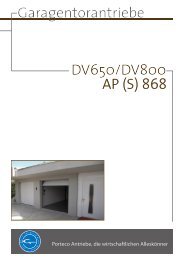
<strong>ekey</strong> ® TOCA<strong>home</strong> <strong>integra</strong> scanner<br />
Status display<br />
Sensor<br />
display<br />
Function display<br />
operating buttons<br />
<strong>ekey</strong> ® TOCA<strong>home</strong> <strong>integra</strong> control panel<br />
31
3. OPERATION<br />
3.1 USING THE OPERATION KEYS OF THE CONTROL PANEL<br />
Programming is carried out via 4 keys<br />
OK key: is used to confirm the entry and to enter the<br />
administration menu.<br />
< and > -keys: to <strong>ch</strong>ange the digits in the display and to<br />
navigate within the menu<br />
(refer to <strong>ch</strong>apter 3.3).<br />
ESC key (X): To cancel the current entry.<br />
PROGRAM, MENU FUNCTIONS AND DISPLAY<br />
Normal operation (blinking dot) .<br />
Enroll user (enroll user) Eu<br />
Delete user (delete user) du<br />
Set security code (Security code) Sc<br />
Reset to initial settings rr<br />
(to delete all settings and data)<br />
3.2 INITIAL START-UP: COUPLING SCANNER AND CONTROL PANEL<br />
When the devices are initially connected to the power supply, the display of the control<br />
panel begins counting backwards until connection has been established with the scanner.<br />
Two red dots are then displayed. During this time the LED light remains red. After<br />
booting is completed, the LED light begins to blink orange. The device can now be<br />
initialised.<br />
Press the OK button and then the ESC button. “EF” (i.e. enrol finger) appears on the<br />
display of the control panel. If a previously recorded finger is drawn over the sensor, the<br />
initialisation process is started without losing existing data. In case no fingers have been<br />
enrolled yet (new installation), press the ESC key to finalize the initialisation process.<br />
Initialisation is carried out fully automatic. The devices are coupled with ea<strong>ch</strong> other to<br />
prevent tampering of the scanner and unauthorised access. The blinking decimal point in<br />
the scanner panel signals normal operation after the initialisation process has been<br />
completed. The security code is set to a default value of 99. Please <strong>ch</strong>ange this code as<br />
soon as possible to a security code of your own <strong>ch</strong>oice.<br />
32
3.3 PROGRAMMING MENU OVERVIEW:<br />
You can move down in the menu using OK. You can move up by using ESC. You can turn<br />
pages or make a <strong>ch</strong>oice using left < and right >.<br />
Eu<br />
Enrole user<br />
1…99<br />
Reset to initial<br />
factory setting<br />
F1,…F9,F0<br />
Set finger<br />
number<br />
01…02<br />
Enter relay<br />
Continue<br />
<strong>ch</strong>apter 3.5<br />
du<br />
1…99<br />
. red blinking dot<br />
Normal operation<br />
0…99<br />
Enter security code<br />
Sc<br />
Delete user Change<br />
security code<br />
Select<br />
user number<br />
Continue<br />
<strong>ch</strong>apter 3.7<br />
0…99<br />
Enter now<br />
security code<br />
Continue<br />
<strong>ch</strong>apter 3.8<br />
rr<br />
Reset to initial<br />
factory setting<br />
0…99<br />
Enter the<br />
security code<br />
Continue<br />
<strong>ch</strong>apter 3.9<br />
33
3.4 RECORDING A FINGER WITH THE SENSOR (SEE PAGE 38)<br />
It is important that the user draws his/her finger correctly across the sensor.<br />
!<br />
34<br />
The best results are a<strong>ch</strong>ieved by using the middle finger while the index<br />
and ring finger stabilize the middle finger.<br />
Place the entire surface of the desired finger after the last joint onto the sensor.<br />
The larger the surface area of the finger, the higher the probability will be that the finger<br />
is recognised by the device the next time it is placed on the sensor.<br />
In order to obtain the best possible recognition performance from the system, please<br />
always swipe your finger over the sensor in the same way you did it when enrolling your<br />
finger.<br />
The sensor is located in the middle of the finger mould (see figure on page 31). Swipe<br />
your finger gently (not too hard and not too soft) and at average speed over the sensor.<br />
People who do a lot of manual work are requested to pay attention to the wear off of<br />
their finger lines, i.e. a right-handed person should record fingers from their left hand<br />
and vice versa.<br />
If you notice that your fingerprints are not so visible, when looking at your fingers with<br />
your bare eyes, please <strong>ch</strong>oose the fingers whi<strong>ch</strong> have the best available fingerprints.<br />
ATTENTION:<br />
Please swipe the largest possible finger surface, starting from the first finger joint and<br />
applying gentle pressure. The larger the scanned finger surface, the easier it will be for<br />
the finger to be recognised.<br />
3.5 HOW TO ENROL A FINGER<br />
You may enrol up to 99 fingers<br />
3.5.1 ENTERING THE SECURITY CODE<br />
� Press the OK-key in the control panel.<br />
� Enter the first digit of the security code using < and > (standard setting is 9)<br />
� Press the OK-key.<br />
� Enter the second digit of the security code using < and > (standard setting is 9)<br />
� Press the OK-key.<br />
� In the display “Eu” (enrol user) is visible.<br />
3.5.2 SETTING ACCESS RIGHTS<br />
� If “Eu” is visible in the display of the control panel, press the OK-key.<br />
� Setting user number: The display shows “1“. If the user ID is already taken, a<br />
red dot appears in the lower right hand corner of the display. Example: “1.”<br />
Select a free user ID by using the < and > keys.<br />
� Press the OK-key.<br />
� Setting finger number: The display shows “F1”. F1 stands for finger 1. Start<br />
counting your fingers from the little finger of the left hand. The little finger of<br />
your right hand would then be number 10 (setting “F0” in the display) e.g. “F7”
would be the pointer finger of your right hand. If a finger ID is already in use a<br />
red dot appears in the lower right hand corner of the display.<br />
� Press the OK-key.<br />
� You can now define the relay whi<strong>ch</strong> is to be activated by the previously selected<br />
finger.<br />
Entering relay: “o1” is visible in the display of the control panel, whi<strong>ch</strong> indicates<br />
that the first relay (motor lock) has been <strong>ch</strong>osen (default setting). Select the<br />
desired relay by using the keys < or > and press the OK-key. Now “EF” will<br />
appear in the display.<br />
Options: „o1“ Relay 1 � typically a motor lock<br />
„o2“ Relay 2 � external relay contact<br />
3.6 ENROLING FINGER<br />
� Once “EF” (enrol finger) is visible in the display of the control panel, you have<br />
60 seconds to swipe your finger over the sensor, starting from the first finger<br />
joint.<br />
� The enrolment should be done as described in <strong>ch</strong>apter 3.4.<br />
� The scanner is equipped with a status display (LED), whi<strong>ch</strong> indicates the<br />
operating mode:<br />
Red: The finger could not be scanned successfully<br />
please try again!<br />
Orange: The device is waiting for a finger to be scanned.<br />
Green: Successful scan<br />
3.7 DELETING A USER FROM THE SYSTEM<br />
3.7.1 ENTERING THE SECURITY CODE<br />
� Press the OK-key in the control panel.<br />
� Enter the first digit of the security code using < and > (standard setting is 9)<br />
� Press the OK-key.<br />
� Enter the second digit of the security code using < and > (standard setting is 9)<br />
� Press the OK-key.<br />
� In the display “Eu” (enrol user) is visible.<br />
3.7.2 DELETING A USER<br />
� Press the >-key until “du” (delete user) is visible in the display of the control<br />
panel.<br />
� Press the OK-key.<br />
� Press the < or >-key to select the user ID to be deleted from the system.<br />
� Confirm the user ID to be deleted by pressing the OK-key.<br />
� In the display of the control panel, “OK” will be visible for a short moment and<br />
the system will return to the standard operating mode.<br />
3.8 CHANGING THE SECURITY CODE<br />
Please note that without the security code you are unable to operate the system. If the<br />
wrong security code is entered 3 times, the system will be disabled for 30 minutes.<br />
35
3.8.1 ENTERING THE CURRENT SECURITY CODE<br />
� Press the OK-key in the control panel.<br />
� Enter the first digit of the security code using < and > (standard setting is 9)<br />
� Press the OK-key.<br />
� Enter the second digit of the security code using < and > (standard setting is 9)<br />
� Press the OK-key.<br />
� In the display “Eu” (enrol user) is visible.<br />
3.8.2 DEFINING A NEW SECURITY CODE<br />
� Press the >-key until “sc” is visible in the display of the control panel.<br />
� Press the OK-key.<br />
� Enter the new first digit of the security code using < and >.<br />
� Press the OK-key.<br />
� Enter the second digit of the security code using < and ><br />
� Press the OK-key.<br />
� In the display of the control panel, “OK” will be visible for a short moment and<br />
the system will return to the standard operating mode.<br />
3.9 RESETTING TO FACTORY SETTINGS<br />
When resetting the system to the initial factory settings, all data from the system is<br />
deleted. The security code is reset to the factory default “99” and the scanner and<br />
control panel loose their coupling.<br />
3.9.1 ENTERING THE CURRENT SECURITY CODE<br />
� Press the OK-key in the control panel.<br />
� Enter the first digit of the security code using < and > (standard setting is 9)<br />
� Press the OK-key.<br />
� Enter the second digit of the security code using < and > (standard setting is 9)<br />
� Press the OK-key.<br />
� In the display “Eu” (enrol user) is visible.<br />
3.9.2 RESETTING TO FACTORY SETTINGS<br />
� Press the >-key until “sc” is visible in the display of the control panel.<br />
� Press the OK-key.<br />
� Enter the first digit of the security code using < and > (standard setting is 9)<br />
� Press the OK-key.<br />
� Enter the second digit of the security code using < and > (standard setting is 9)<br />
� Press the OK-key.<br />
� In the display of the control panel, “OK” will be visible for a short moment and<br />
two red dots will appear. The system has been reset to the factory settings.<br />
36
4. USING THE FINGER SCANNER<br />
Swiping your finger in the right way over the finger scanner is the most important<br />
element in order to allow the product to function properly.<br />
Please use the fingers whi<strong>ch</strong> you consider to have the most definite fingerprints.<br />
Especially if you do not have very definite fingerprints, then you exert as less pressure as<br />
possible on the scanner when swiping your finger over it, so that the fingerprints not be<br />
squashed.<br />
The finger scanner features a full automatic learning system, whi<strong>ch</strong> guarantees a lasting<br />
recognition performance.<br />
In order to optimize finger recognition, swipe ea<strong>ch</strong> finger at least 5 times over the<br />
scanner. Should your swipes not be declined, then please try again.<br />
In case finger recognition performance is too low, please try the following:<br />
� Reduce pressure when swiping your finger.<br />
� Take care to place your finger in the designated place on the device.<br />
� Use the finger surface starting from the first. Almost everybody has a strong<br />
fold at the joint, this is where you should start to have your finger scanned.<br />
� Generally the best finger is the middle finger.<br />
� The little finger and the thumb are not the best fingers for ergonomic reasons.<br />
The thumb is very hard to use.<br />
� Try to swipe your finger at different speeds, so as to define whi<strong>ch</strong> is the best<br />
speed for your fingers.<br />
� Register the same finger in several storage places if the indications above do not<br />
help. You have 99 storage places. In extreme cases, you should use up to 10<br />
storage places for one single finger.<br />
� Wet fingers have slightly modified line <strong>ch</strong>aracteristics, whi<strong>ch</strong> can be noticed with<br />
your bare eyes. In case your fingers are often wet, then you should register<br />
them when wet.<br />
� Child fingers can only be registered from 5 years on approximately, please also<br />
bear in mind the items listed above.<br />
37
5. TROUBLESHOOTING<br />
Problem Cause Solution<br />
I am unable to enrol a<br />
finger.<br />
An enroled finger cannot be<br />
identified.<br />
1. The finger has not been<br />
swiped consistently over the<br />
sensor, starting from the<br />
first finger joint.<br />
2. The finger has been<br />
swiped too softly or too<br />
strongly over the sensor.<br />
3. The finger has been<br />
swiped too fast or too slowly<br />
over the sensor.<br />
4. The way (angle) the finger<br />
lays on the sensor is not<br />
right.<br />
5. The finger does not have<br />
enough minutia in order to<br />
be enrolled (wearout).<br />
1. During enrolment, a<br />
different area of the finger<br />
was scanned.<br />
2. The enrolment has not<br />
been carried out correctly.<br />
3. The finger is not being<br />
swiped correctly over the<br />
2. The power supply has<br />
been interrupted � the<br />
system is starting again.<br />
1. Swipe the finger<br />
consistently over the sensor<br />
starting from the first finger<br />
joint.<br />
2. Swipe the finger gently,<br />
but not too softly over the<br />
sensor.<br />
3. Swipe the finger with<br />
moderate speed over the<br />
sensor (see page 37).<br />
4. Use another finger.<br />
1. The finger has to be<br />
enroled again by swiping it<br />
consistently over the sensor.<br />
2. See “I am unable to enrol<br />
a finger” – perfect enrolment<br />
ensures high identification<br />
rates.<br />
scanner.<br />
3. See page 37.<br />
Status point of the control System not connected 1. Ensure power supply,<br />
panel is not blinking. to the power supply. <strong>ch</strong>eck the glass tube fuse<br />
Two blinking dots on the No or incorrect device Coupling should be done<br />
control panel display coupling<br />
again (see 3.2 on page 32<br />
"Initial start-up")<br />
Error code “E0” on the 1. Connection between 1. Check the “4-pole”<br />
display followed by scanner and control panel is connection wire. Check<br />
countdown starting from 45 not correct.<br />
power voltage at clamps 3,4<br />
min. 8V<br />
Error code “E1” on the<br />
display<br />
99 fingers have already been<br />
enroled. It is not possible to<br />
enrol more fingers.<br />
2. Wait until the system has<br />
initialised again.<br />
No more fingers may be<br />
enroled. Erase some fingers<br />
in order to enrol new ones.<br />
39
Problem Cause Solution<br />
Error code “E2“on the<br />
display<br />
Error code "E3" on the<br />
display<br />
The green LED on the<br />
scanner is signalling a<br />
positive identification,<br />
however the relay is not<br />
released.<br />
Status LEDs blink green and<br />
red in the finger scanner.<br />
40<br />
Incorrect security code has<br />
been entered three times. 30<br />
min. lock-out.<br />
Wait for 30 min, enter<br />
the correct security code<br />
again.<br />
Wrong device coupling Couple the devices again,<br />
one of them has been<br />
manipulated.<br />
Wrong unit coupling.<br />
The finger is not accepted,<br />
as a device has been<br />
swapped.<br />
Possible problem or damage<br />
on the sensor.<br />
Couple the devices again,<br />
one of them has been<br />
manipulated.<br />
Reset the device before<br />
coupling it (see 3.9).<br />
Contact our support<br />
department. Take care that<br />
you have the serial number<br />
of all units at hand (<strong>ch</strong>eck<br />
the barcode stickers). For<br />
contact data <strong>ch</strong>eck page 29.
6. TECHNICAL SPECIFICATIONS<br />
• CONNECTIONS<br />
Connection between scanner and control panel<br />
Supply voltage<br />
Output for direct motor lock connection (screw clamp)<br />
Relay output via main plug<br />
RS485 interface via main plug<br />
Potential free gate input via main plug<br />
Power supply (AC or DC) via main plug<br />
• MEMORY<br />
99 fingers possible<br />
No loss of data after power failure<br />
• SECURITY<br />
Coupling between scanner and control panel<br />
Extremely low rate of false identification (FAR 1x 10 -6 for FRR 1,4x10 -2 )<br />
• ELECTRICAL DATA<br />
Input voltage: 8V – 24V AC<br />
8V – 30V DC<br />
Input capacity: ~ 1W (without motor lock)<br />
Swit<strong>ch</strong>ing capacity: 30V 2A<br />
Motor lock capacity: 30V 2A<br />
• AMBIENT CONDITIONS<br />
Temperature range: -40°C … +85°C<br />
Protection category: Control panel IP41 (when mounted)<br />
Finger scanner IP43<br />
• SPEED<br />
Recognition time 1s to 4s<br />
(depending on the amount of stored fingers and on operation)<br />
Enrolment time ~4s per finger<br />
41
6.1 CONNECTOR CONFIGURATION OF THE INTEGRA CONTROL PANEL<br />
JMP2<br />
42<br />
3<br />
1<br />
4 2<br />
8<br />
4<br />
2<br />
1<br />
3<br />
5<br />
1<br />
X3: Connector set to the finger scanner<br />
Pin No. Cable color Function<br />
1 Yellow RS485 communication (terminal 2)<br />
2 Green RS485 communication (terminal 1)<br />
3 Brown Power supply (terminal 3)<br />
4 White Power supply (terminal 4)<br />
JMP2: Defines how relay 2 should work<br />
Normally open contact Normally closed contact<br />
(NO) (NC)<br />
X6: Relay 1 screw terminal to connect the motor lock<br />
Terminal No. Function<br />
1 Power supply motor lock + (equ. white X1)<br />
2 Power supply motor lock - (equ. brown X1)<br />
3 Swit<strong>ch</strong>ing impulse (swit<strong>ch</strong>ed white X1)<br />
X1: Main connector plug<br />
1<br />
Pin No. Cable color Function<br />
1 Blue Gate input terminal 1<br />
2 Grey Gate input terminal 2<br />
3 Yellow <strong>ekey</strong> TOCA<strong>home</strong> terminal 2<br />
4 Green <strong>ekey</strong> TOCA<strong>home</strong> terminal 1<br />
5 Brown Power supply DC- or AC<br />
6 White Power supply DC+ or AC<br />
7 Pink Relay 2 C<br />
8 Red Relay 2 NO / NC (see JMP1)<br />
2<br />
3
6.2 DIMENSIONS OF THE INTEGRA CONTROL PANEL<br />
Shield width:<br />
43
6.3 DIMENSIONS OF THE INTEGRA FINGER SCANNER<br />
44<br />
Finger swiping track<br />
Deta<strong>ch</strong>able<br />
mounting pins<br />
RJ45 connector
7. MOUNTING AND INSTALLATION<br />
7.1 CONTROL PANEL CUTOUT<br />
Ausfräsung für die Inneneinheit <strong>integra</strong><br />
X<br />
< ><br />
OK<br />
273.00<br />
254.00<br />
233.25<br />
Die Fräsbreite ist Modellabhängig und beträgt:<br />
Cutout width depends on the model:<br />
Fräsbreiten: 18mm, 20mm oder 24mm<br />
18mm, 18mm, 20mm 20mm or oder 24mm 24mm<br />
30.0<br />
Türblatt Door<br />
Bohrungen f. Befestigungss<strong>ch</strong>rauben<br />
Drilling for screws (optional)<br />
(optional)<br />
Outlet for the X1, X3, X6 wiring<br />
(to Auslass finger für Kabelzuführung<br />
scanner, motor lock and main cable.<br />
(von Außeneinheit, Motors<strong>ch</strong>loss und Hauptzuleitung,<br />
Cutout position is arbitrary).<br />
die Position der Ausnehmung ist frei wählbar)<br />
min. 8mm 15mm<br />
45
7.2 FINGERSCANNER CUTOUT<br />
46<br />
5mm angle or radius<br />
(at all 4 angles)<br />
Connector outlet<br />
Type 1 (mounting pin) Type 2 (screws)<br />
* recommended milling dimensions (depending on the material)
7.3 CONTROL PANEL MOUNTING<br />
7.3.1 CUTOUT<br />
To install the <strong>ekey</strong> ® TOCA<strong>home</strong> <strong>integra</strong> control panel, prepare a cutout according to the<br />
figure on page 45.<br />
7.3.2 WIRING<br />
When installing the cables, please take care to have enough cable buffer left to plug the<br />
device in and out, so that you can still build the device in.<br />
7.3.3 ELECTRIC CONNECTION<br />
The control panel is powered by the white and brown wire of the 8-pole main cable X1.<br />
For DC power supply, please connect the white cable to the positive (+) pole and the<br />
brown cable to the negative (-) pole. When using AC power supply, you need to connect<br />
the brown as well as the white cable to the AC adapter.<br />
The power source capability should be defined so that there is enough power both for<br />
<strong>ekey</strong> ® TOCA<strong>home</strong> <strong>integra</strong> (approx. 1W) and the consumer load at relay 1 (X6).<br />
For instance: motor lock 24VDC 1A + <strong>ekey</strong> ® TOCA<strong>home</strong> <strong>integra</strong> at 24VDC approx.<br />
100mA. Power supply should be in this case at least 27 Watt, so 24VDC 1,1A.<br />
The power supply for the motor lock (optional) is taken directly from the control panel<br />
(3-pole X6 screw terminal).<br />
7.3.4 CONNECTING A MOTOR LOCK<br />
To connect a motor lock, please use the X6 screw terminal. Connect the positive (+)<br />
output of the control panel to the positive (+) input if the motor lock. The minus pole and<br />
the impulse output need to be connected in the same way.<br />
X6<br />
Swit<strong>ch</strong>ing impulse 3<br />
Power Supply Motor lock (-) 2<br />
Power Supply Motor lock (+) 1<br />
ATTENTION:<br />
The electrical unit should be installed by a qualified te<strong>ch</strong>nician.<br />
47
7.4 FINGER SCANNER MOUNTING<br />
The <strong>ekey</strong> ® TOCA<strong>home</strong> <strong>integra</strong> finger scanner can be installed in two different ways.<br />
Installation with mounting pins:<br />
When mounting the scanner into a door it is necessary to mill an adequate space (refer<br />
to the figure on page 46). Allow easy seating of the scanner while the RJ-45 cable is<br />
connected to the scanner. This is a<strong>ch</strong>ieved by drilling an extra not<strong>ch</strong> for the cable with<br />
the RJ-45 tip. This extra not<strong>ch</strong> has to be inside the door (not visible from outside) in the<br />
bottom of the opening where the scanner will be seated.The cable has to be laid inside<br />
the door and extend through the door all the way out to the control panel.<br />
Now connect the <strong>integra</strong> scanner with the cable and place it inside the not<strong>ch</strong>. The two<br />
pins of the <strong>integra</strong> scanner have to rea<strong>ch</strong> the designated holes, in order to be tightened<br />
with the provided screws. While tightening the screws, please press the <strong>integra</strong> scanner<br />
lightly against the door blade, in order to guarantee a fixed hold of the <strong>integra</strong> scanner.<br />
Mount the provided design element only after you have finished installing the whole<br />
system.<br />
Installation without mounting pins:<br />
In order to install the scanner without mounting pins (e.g. in a door frame) the pins have<br />
to be cut off the case.<br />
Make an opening in the frame (refer to the figure on page 46) and drill two holes for the<br />
mounting screws (approx. 2mm diameter). Pull the cable from the cut for the finger<br />
scanner up to the mounting position of the control panel. Please take care that the end<br />
of the cable with the RJ45 plug is on the mounting position for the scanner. Now insert<br />
the RJ45 plug into the <strong>integra</strong> scanner and place it to the designated cut. Once properly<br />
seated, screw the scanner onto the wall with the provided screws. Please pay attention<br />
while tightening the screws not to overtighten them, as the housing could then be<br />
damaged Mount the provided design element only after you have finished to install the<br />
whole system.<br />
Please leave about 10cm room<br />
on both sides of the <strong>integra</strong><br />
scanner to guarantee a proper<br />
use of the device with any<br />
finger (refers to both mounting<br />
possibilities).<br />
48
7.5 CONTROL PANEL AND FINGER SCANNER MOUNTING HEIGHT<br />
1550m m<br />
Fingerscanner<br />
Finger Scanner<br />
<strong>Steuereinheit</strong><br />
Control Panel<br />
ca. 1300m m<br />
49
7.6 DESIGN ELEMENT MOUNTING<br />
7.7 DESIGN ELEMENT DISMOUNTING<br />
50<br />
Installing the design element is<br />
done by snapping it over the <strong>integra</strong><br />
finger scanner as follows: using two<br />
fingers, grab the design element<br />
on the sides from the middle. Align<br />
and insert the design element<br />
bottom two not<strong>ch</strong>es in the scanner<br />
two bottom holes.<br />
While the bottom edge of the<br />
design element is in this position,<br />
apply little pressure on the top face<br />
towards the scanner forming a little<br />
curve (avoid bending the plate).<br />
While in this position, align the<br />
not<strong>ch</strong>es on the top edge of the<br />
design element into the scanner<br />
two top holes. Once seated rrelease<br />
your fingers and the design<br />
element is in place.<br />
In order to dismount the design<br />
element, use a flat object (flat<br />
screwdriver or the like) and lift the<br />
design element out of the frame<br />
carefully, by placing the flat object<br />
in-between between the upper or the lower<br />
edge of the plastic housing and the<br />
design element element.
8. WIRING EXAMPLES<br />
8.1 MINIMUM INSTALLATION<br />
<strong>ekey</strong> ® TOCA<strong>home</strong> <strong>integra</strong> control panel and <strong>ekey</strong> ® TOCA<strong>home</strong> <strong>integra</strong> finger scanner<br />
together with a motor lock or electric strike. All components are <strong>integra</strong>ted in the door.<br />
This example shows the most simple implementation. In this one case, apart from the<br />
power supply, no further elements are necessary outside the door. If you wish to connect<br />
an electric strike, then please do so via the supply- and swit<strong>ch</strong> impulse lead.<br />
Control panel<br />
Connection to the finger scanner<br />
(type A cable)<br />
Connection to the motor lock or<br />
to the electric strike<br />
(type C cable)<br />
Main cable<br />
(type B cable)<br />
Terminal:<br />
motor lock<br />
Swit<strong>ch</strong>ing impuls<br />
Supply -<br />
Supply +<br />
Terminal:<br />
electric strike<br />
Power supply DC+ (or AC)<br />
white<br />
Power supply DC- (or AC)<br />
brown<br />
51
8.2 INSTALLATION USING AN EXTERNAL SWITCH AND CONSUMER LOAD<br />
<strong>ekey</strong> ® TOCA<strong>home</strong> <strong>integra</strong> control panel and <strong>ekey</strong> ® TOCA<strong>home</strong> <strong>integra</strong> finger scanner<br />
together with a motor lock. Moreover an external device is connected via relay 2. All<br />
components are <strong>integra</strong>ted in the door.<br />
This example shows how to install the <strong>ekey</strong> ® TOCA<strong>home</strong> <strong>integra</strong> control panel when using<br />
a motor lock as well as an external swit<strong>ch</strong> (e.g. intercom) in order to activate a consumer<br />
load (alarm system, garage door drive me<strong>ch</strong>anism, rejection relay for <strong>ekey</strong> ® TOCA<strong>home</strong><br />
pc <strong>integra</strong>, etc.)<br />
52<br />
Control panel<br />
Connection to the finger scanner<br />
(type A cable)<br />
Connection to the motor lock or<br />
to the electric strike<br />
(type C cable)<br />
Main cable<br />
(type B cable)<br />
Swit<strong>ch</strong>ing impuls<br />
Supply -<br />
Supply +<br />
Green Terminal 1<br />
Yellow Terminal 2<br />
White Supply + (or AC)<br />
Brown Supply - (or AC)<br />
Blue Input terminal 1<br />
Grey Input terminal 2<br />
Pink Relay 2 C<br />
Red Relay 2 NO / NC<br />
supply<br />
ext. swit<strong>ch</strong><br />
Electric strike<br />
(or garage door)
8.3 INSTALLATION WITH STANDARD CONTROL PANEL<br />
When using the standard control panel instead of the <strong>integra</strong> on, please apply the<br />
following wiring diagram.<br />
Finger Scanner<br />
<strong>integra</strong><br />
Converter<br />
(optional)<br />
Green<br />
Yellow<br />
Control Panel<br />
Door strike<br />
Brown<br />
White<br />
53
9. MANUFACTURERS' GUARANTEE<br />
Model<br />
Serial No.<br />
Buyer’s name and address<br />
Invoice number<br />
Date of invoice<br />
Dealer’s stamp<br />
Under the conditions at hand, <strong>ekey</strong> guarantees its product being free of production and processing errors over a period<br />
of<br />
26 months starting from the production date.<br />
The guarantee performance may only be enforced in that country in whi<strong>ch</strong> it was first sold to an ultimate buyer.<br />
Manufacturing of ea<strong>ch</strong> product is stored on a log file. Guarantee expiry can be tracked anytime via internet -<br />
http://www.<strong>ekey</strong>.net/warranty.htm - using the serial number. The duration of the guarantee can be extended to<br />
a limit of 6 months more, under the condition that an invoice is provided.<br />
In case of a guarantee claim, a defective unit will be repaired or substituted to restore full operability. The guarantee<br />
period is basically six (6) months for accumulators and twelve (12) months following the delivery for LCD displays.<br />
The enforcement of further claims by the buyer/user, particularly claims based on possible concomitant and resultant<br />
damage within the framework of the guarantee settlement is explicitly excluded, in any case, however, it is limited to<br />
deliberate or grossly negligent acting or default of ‘<strong>ekey</strong>’. A liability for the loss of business opportunities, data or<br />
programmes and the loss of profit of the contract partner is excluded in any case.<br />
Having a defective unit repaired or replaced will not result in an extension or recommencement of the product<br />
guarantee.<br />
To enforce one’s guarantee claims the number and date of the invoice, and the defect needs to be stated and is to be<br />
handed in/delivered free to ‘<strong>ekey</strong>’/the service partner or distributor of the respective country (quod vide<br />
www.<strong>ekey</strong>.net).<br />
In the event of sending the product complained about, the costs for the transport to ‘<strong>ekey</strong>’/the service partner will be<br />
borne and the risk of a possible loss or of a delay during the transport will be taken by the person enforcing the claim,<br />
and for that reason, concluding appropriate insurance is recommended. ‘<strong>ekey</strong>’ assumes no liability for transport<br />
damages resulting from inappropriate or insufficient packaging.<br />
No guarantee claims can be accepted for products that were damaged or made unable to operate 1) by using the<br />
product for a purpose for whi<strong>ch</strong> they were not intended, non-observance of the notes for the user contained in the<br />
Instructions for Use and/or in the Guarantee Certificate delivered together with the product, or by any other incorrect<br />
use of the product, e.g. if the contractually provided goods were operated together with su<strong>ch</strong> devices or programmes<br />
the compatibility of whi<strong>ch</strong> was not explicitly confirmed by ‘<strong>ekey</strong>’,<br />
2) by <strong>ch</strong>anging the product,<br />
3) by attempts to repair the product by a third person, i.e. not by ‘<strong>ekey</strong>’ or a service partner authorised by ‘<strong>ekey</strong>’,<br />
4) by improper transport or improper package for the return of the product to ‘<strong>ekey</strong>’ or a service partner of ‘<strong>ekey</strong>’,<br />
5) by incorrect handling or as a result of me<strong>ch</strong>anical load (su<strong>ch</strong> as percussions, dropping, high pressure or similar)<br />
6) by improper installation of products provided by third persons, as well as for products that ‘<strong>ekey</strong>’ obtained from a<br />
sub supplier about whose property court proceedings due to insolvency was initiated at the time of the enforcement of<br />
the guarantee claims, or su<strong>ch</strong> proceedings were imminent.<br />
Traces of daily usage (scrat<strong>ch</strong>es, dents, small rifts, etc.) are no reason for a warranty claim.<br />
Any damage to or breaking of the factory-made seal will result in an irrevocable termination of all warranty claims.<br />
Interventions are meant to be carried out exclusively of people authorized by ‘<strong>ekey</strong>’ under antistatic conditions. If you<br />
discover any shortcomings, whi<strong>ch</strong> result in even more serious defects by continuous usage, those consequential<br />
damages cannot be repaired in the range of the guarantee.<br />
After giving a quotation we do explicitly reserve the right to <strong>ch</strong>arge a service fee, if the unrepaired device is demanded<br />
back.<br />
Please pay attention to <strong>ch</strong>apter 5 and 6 of <strong>ekey</strong>’s terms and conditions in this context.<br />
We wish you a lot of joy with the innovative quality solutions of ‘<strong>ekey</strong>’.<br />
<strong>ekey</strong> biometric systems GmbH<br />
Lunzerstrasse 64<br />
4030 Linz<br />
www.<strong>ekey</strong>.net<br />
55
56<br />
<strong>ekey</strong> biometric systems GmbH<br />
Lunzerstraße 64<br />
A- 4030 Linz<br />
www.<strong>ekey</strong>.net<br />
Optis<strong>ch</strong>e und te<strong>ch</strong>nis<strong>ch</strong>e Änderungen, Satz- und Druckfehler vorbehalten 800733/0738<br />
Subject to optical and te<strong>ch</strong>nical modifications, any liability for misprints excluded