MONTAGEANLEITUNG ekey home (net) integra - Gueller.ch
MONTAGEANLEITUNG ekey home (net) integra - Gueller.ch
MONTAGEANLEITUNG ekey home (net) integra - Gueller.ch

Create successful ePaper yourself
Turn your PDF publications into a flip-book with our unique Google optimized e-Paper software.
<strong>MONTAGEANLEITUNG</strong> <strong>ekey</strong> <strong>home</strong> (<strong>net</strong>) <strong>integra</strong><br />
HINWEIS ZUM DOKUMENT<br />
Diese Montageanleitung als au<strong>ch</strong> die zusätzli<strong>ch</strong>en Informationen und Anleitungen<br />
auf der beiliegenenden DVD unterliegen keinem Änderungsdienst. Die letztgültige<br />
Version dieser Dokumente finden Sie unter www.<strong>ekey</strong>.<strong>net</strong>. Optis<strong>ch</strong>e und<br />
te<strong>ch</strong>nis<strong>ch</strong>e Änderungen, Satz- und Druckfehler bleiben vorbehalten.<br />
ACHTUNG !<br />
Bitte bea<strong>ch</strong>ten Sie zu dieser Anleitung unbedingt au<strong>ch</strong> die Informationen<br />
auf der beiliegenden DVD.<br />
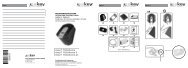
LIEFERUMFANG<br />
FINGERSCANNER STEUEREINHEIT KURZANLEITUNG <strong>MONTAGEANLEITUNG</strong> DVD<br />
2 STK. SCHRAUBEN 2 STK. SCHRAUBEN DEKORELEMENT<br />
LK 2.9 X 19 LK 2.9 X 38<br />
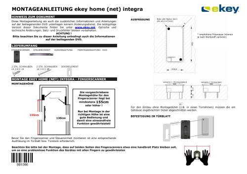
MONTAGE EKEY HOME (NET) INTEGRA - FINGERSCANNER<br />
MONTAGEHÖHE<br />
m 155cm<br />
Fingerscanne<br />
r<br />
Steuereinhei<br />
t<br />
130cm<br />
Bevor Sie den Fingerscanner und Steuereinheit montieren ist eine entspre<strong>ch</strong>ende<br />
Ausfräsung im Türblatt bzw. Türstock erforderli<strong>ch</strong>.<br />
m<br />
130<br />
c<br />
Die vorges<strong>ch</strong>riebene<br />
Montagehöhe für den<br />
Fingerscanner liegt bei<br />
mindestens 155cm<br />
oder höher !<br />
Nur bei Montage in der<br />
ri<strong>ch</strong>tigen Höhe ist eine<br />
gute Bedienung und<br />
damit eine einwandfreie<br />
Funktion gewährleistet!<br />
AUSFRÄSUNG<br />
Für den Einbau ohne Montagedübel (z.B. in einen Türrahmen) müssen die am<br />
Gehäuse angebra<strong>ch</strong>ten Dübel abges<strong>ch</strong>nitten werden.<br />
BEFESTIGUNG IM TÜRBLATT<br />
Bea<strong>ch</strong>ten Sie bitte bei der Montage, dass auf beiden Seiten des Fingerscanners etwa eine handbreit Platz bleiben soll,<br />
um so eine problemlose Funktion des Gerätes mit allen Fingern zu gewährleisten<br />
* empfohlene Fräsmasse (können<br />
je na<strong>ch</strong> Werkstoff variieren)
MONTAGE <strong>ekey</strong> <strong>home</strong> Aufputz<br />
AUSFRÄSUNG UND MONTAGE EKEY HOME (NET) INTEGRA<br />
STEUEREINHEIT<br />
Ausfräsung für die Inneneinheit <strong>integra</strong><br />
X<br />
< ><br />
OK<br />
273.00<br />
254.00<br />
Fräsbreiten: 18mm, 20mm oder 24mm<br />
233.25<br />
30.0<br />
Türblatt<br />
Bohrungen f. Befestigungss<strong>ch</strong>rauben<br />
(optional)<br />
Auslass für Kabelzuführung<br />
(von Außeneinheit, Motors<strong>ch</strong>loss und Hauptzuleitung,<br />
die Position der Ausnehmung ist frei wählbar)<br />
min. 8mm<br />
TECHNISCHE DATEN<br />
Te<strong>ch</strong>nis<strong>ch</strong>e Daten<br />
<strong>ekey</strong> <strong>home</strong> (<strong>net</strong>) Fingerscanner <strong>integra</strong><br />
Einheit <strong>ekey</strong> <strong>home</strong> <strong>integra</strong><br />
Versorgung VAC 8-24<br />
VDC 8-30<br />
Leistungsaufnahme W ca.1<br />
Temperaturberei<strong>ch</strong> °C -40 bis +85<br />
Spei<strong>ch</strong>er Finger <strong>home</strong>:99 <strong>net</strong>: 40/200/2000<br />
Si<strong>ch</strong>erheit FAR 1x 10 -6<br />
FRR 1,4x 10 -2<br />
S<strong>ch</strong>utzart IP 54 (frontseitig)<br />
Ges<strong>ch</strong>windigkeit s 1-4<br />
Lebendauer Fingerscans max. 4 Mio<br />
Te<strong>ch</strong>nis<strong>ch</strong>e Daten <strong>ekey</strong> <strong>home</strong><br />
(<strong>net</strong>) Steuereinheiten <strong>integra</strong><br />
Einheit <strong>ekey</strong> <strong>home</strong><br />
<strong>integra</strong><br />
<strong>ekey</strong> <strong>home</strong> <strong>integra</strong> 2,<br />
pc<br />
<strong>ekey</strong> <strong>net</strong> <strong>integra</strong><br />
Versorgung VAC 8-24 8-24<br />
VDC 8-30 8-30<br />
Leistungsaufnahme W ca.1 ca.1<br />
Relais<br />
RELAIS<br />
Anzahl 1 2<br />
S<strong>ch</strong>altleistung Relais 42VDC(AC)/2A 42VDC(AC)/2A<br />
Maximale Spannung (Peak AC) VAC(DC) 60 60<br />
EIN- Widerstand (max.) Ω 0,12 0,12<br />
Leckstrom µA 1 1<br />
Eins<strong>ch</strong>altzeit ms 1.5 1.5<br />
Auss<strong>ch</strong>altzeit ms 0.5 0.5<br />
Temperaturberei<strong>ch</strong> °C -40 bis +85 -40 bis +85<br />
S<strong>ch</strong>utzart IP 40 (Frontseite) 40(Frontseite)<br />
Digitale Eingänge 1 1<br />
Maximaler Strom an X6 PIN 1 (nur<br />
bei Integra)*<br />
A 3 3<br />
Es steht 1 Relais (2 Relais in der Variante <strong>ekey</strong> <strong>home</strong> 2, pc und <strong>ekey</strong> <strong>net</strong>) zum<br />
Ansteuern von externen Geräten zur Verfügung. Relais 1 verfügt über einen<br />
potentialfreien bzw. potentialbehafteten S<strong>ch</strong>ließer der über JP1 konfigurierbar (Ist<br />
JP1 ni<strong>ch</strong>t bestückt, so ist immer der potentialbehaftete S<strong>ch</strong>ließer in Funktion) ist.<br />
Relais 2 ist generell potentialfrei und kann über JP2 als Öffner oder S<strong>ch</strong>ließer<br />
konfiguriert werden. Die maximale S<strong>ch</strong>altleistung beträgt 42V / 2A.<br />
Das Verbindungskabel zwis<strong>ch</strong>en Steuereinheit und Fingerscanner ist getrennt von<br />
der Hauselektroinstallation zu verlegen, da dieses Signale im<br />
Niederspannungsberei<strong>ch</strong> führt, die dur<strong>ch</strong> bena<strong>ch</strong>barte stromführende Kabel<br />
gestört werden können.<br />
Die Ans<strong>ch</strong>lüsse sind ni<strong>ch</strong>t verpolungsges<strong>ch</strong>ützt! Ein fals<strong>ch</strong>er elektris<strong>ch</strong>er<br />
Ans<strong>ch</strong>luss des Systems kann zur Zerstörung des Gerätes führen.<br />
Die Herstellung der elektris<strong>ch</strong>en Verbindungen und der Ans<strong>ch</strong>luss an die<br />
Netzversorgung darf auss<strong>ch</strong>ließli<strong>ch</strong> dur<strong>ch</strong> Fa<strong>ch</strong>personal dur<strong>ch</strong>geführt<br />
werden!
PINBELEGUNG EKEY HOME (NET) INTEGRA<br />
X3- Verbindung zu<br />
Fingerscanner<br />
Arbeitsweise<br />
Relais 1<br />
Funktion potentialfrei,<br />
S<strong>ch</strong>ließer (NO)<br />
Funktion = mit<br />
S<strong>ch</strong>altspannung<br />
(Werkseinstellung)<br />
X1 - Hauptzuleitung PIN Kabel Typ B<br />
Farbe<br />
S<strong>ch</strong>alteingang 1<br />
S<strong>ch</strong>alteingang 2<br />
RS485 (KLEMME 2)<br />
RS485 (KLEMME 1)<br />
Versorgung DC- oder AC (KLEMME<br />
3)<br />
Versorgung DC + oder AC (KLEMME<br />
4)<br />
Relais 2 C<br />
Relais 2 NO/NC je na<strong>ch</strong><br />
JP1<br />
1 2<br />
2 3<br />
PIN<br />
Arbeitsweise<br />
Relais 2<br />
Funktion<br />
S<strong>ch</strong>ließer (NO)<br />
Funktion<br />
Öffner (NC)<br />
1<br />
2<br />
3<br />
4<br />
5<br />
6<br />
7<br />
8<br />
Kabel<br />
Typ A<br />
Farbe<br />
RS485 (KLEMME 2) 1 gelb<br />
RS485 (KLEMME 1) 2 grün<br />
Versorgung für Fingersc. (KLEMME 3) 3 braun<br />
Versorgung für Fingersc. (KLEMME 4) 4 weiss<br />
blau<br />
grau<br />
gelb<br />
grün<br />
braun<br />
weiss<br />
rosa<br />
rot<br />
JP2<br />
X6 – RELAIS 1 Ans<strong>ch</strong>luss & Funktion PIN<br />
JP1 =<br />
JP1 = mit<br />
POTENTIALFREI<br />
SCHALTSPANNUNG<br />
Kontakt C (common) Versorgung Motors<strong>ch</strong>loss<br />
(+) (Spannung von von X1,<br />
Pin 6, weiss)<br />
1<br />
FREI – NICHT BELEGEN Versorgung Motors<strong>ch</strong>loss (-)<br />
(Spannung von X1, Pin 5,<br />
braun)<br />
2<br />
Kontakt NO (= S<strong>ch</strong>altimpuls<br />
3<br />
S<strong>ch</strong>ließer)<br />
(Spannung X1, Pin 6,<br />
weiss, wird hier über<br />
Relais 1 ges<strong>ch</strong>alten)<br />
2<br />
1<br />
3<br />
2<br />
1 2 3 JP1<br />
3<br />
2<br />
1<br />
X3<br />
3 1<br />
4 2<br />
3<br />
2<br />
1<br />
JP2<br />
X6<br />
8 7 6 5<br />
4 3 2 1<br />
X1<br />
X6<br />
8<br />
4<br />
X1<br />
3<br />
4<br />
X3<br />
7<br />
3<br />
1<br />
2<br />
3<br />
2<br />
1<br />
6<br />
2<br />
Kabel<br />
Typ A<br />
Kabel<br />
Typ C<br />
5<br />
1<br />
Belegung RJ45<br />
Kabel<br />
PIN Typ A<br />
Farbe<br />
RS485 (KLEMME 2) 5 gelb<br />
RS485 (KLEMME 1) 4 grün<br />
Versorgung für Fingersc.<br />
(KLEMME 3)<br />
7 braun<br />
Versorgung für Fingersc.<br />
(KLEMME 4)<br />
8 weiss<br />
Kabel<br />
Typ B<br />
RELAIS 1<br />
Motors<strong>ch</strong>loss oder Türöffner:<br />
Ans<strong>ch</strong>luss entspre<strong>ch</strong>end der<br />
Bedienungsanleitung des<br />
Motors<strong>ch</strong>losses dur<strong>ch</strong>führen !<br />
RELAIS 2: Beispiel: Steuersignal<br />
für eine Alarmanlage<br />
(potentialfreier Kontakt)<br />
Taster für manuelle Türöffnung z.B.<br />
bei Spre<strong>ch</strong>anlage<br />
<strong>ekey</strong> converter LAN<br />
<strong>ekey</strong> converter UDP<br />
<strong>ekey</strong> converter USB *)<br />
Power<br />
Supply<br />
Power<br />
Supply<br />
*) bei <strong>ekey</strong> converter USB sind Klemme 3 und 4 (Power<br />
supply) ni<strong>ch</strong>t zu belegen.<br />
1<br />
2<br />
3<br />
4<br />
8<br />
1
MONTAGE <strong>ekey</strong> <strong>home</strong> Aufputz<br />
VERKABELUNGSBEISPIEL EKEY HOME (NET) INTEGRA MIT TÜRÖFFNER UND EFF EFF TÜRÜBERGANG<br />
Die im folgenden Verkabelungsplan dargestellten Kabel sind Standardkabel von <strong>ekey</strong>, die sie fertig konfektioniert, in unters<strong>ch</strong>iedli<strong>ch</strong>en Längen bei <strong>ekey</strong> erhalten können.<br />
Kabel Typ A: Verbindung Steuereinheit – Fingerscanner<br />
Kabel TypB: Verbindung zu externen Systemen<br />
Kabel Typ C: Verbindung Steureinheit Motors<strong>ch</strong>loss (Türöffner)<br />
Die Zuweisung der Adernfarben, ist natürli<strong>ch</strong> nur bei Verwendung dieser Kabel gültig ! Generell empfiehlt <strong>ekey</strong> die Verwendung obgenannter Kabel !<br />
blau<br />
grau<br />
gelb<br />
grün<br />
braun<br />
weiss<br />
rosa<br />
rot<br />
X3<br />
X6<br />
X1<br />
801066: Version 2 vom 22.6.09<br />
3<br />
2<br />
1<br />
S<strong>ch</strong>alteingang 1<br />
S<strong>ch</strong>alteingang 2<br />
RS485 (Kl.2)<br />
RS485 (Kl.1)<br />
(-)VCC (Kl.3)<br />
(+)VCC (Kl.4)<br />
REL2 C<br />
REL2<br />
Kabel Typ A<br />
grün<br />
braun<br />
(+) Swit<strong>ch</strong><br />
(-) Gnd<br />
weiss (+) VCC<br />
Kabel<br />
Typ C<br />
Kabel Typ<br />
Kabel Typ B1<br />
Kabel Typ A<br />
<strong>ekey</strong><br />
Kabelübergang<br />
100880<br />
100881<br />
Kabel Typ C<br />
Kabel<br />
Typ C<br />
Steuereinheit und Fingerscanner müssen mit einem 4-adrigen Kabel mit 0,14 mm² Aderquers<strong>ch</strong>nitt verbunden werden. Bei<br />
Distanzen über 50 m muss für die stromführenden Adern (Ans<strong>ch</strong>lüsse 3 u. 4) ein Kabel mit größerem Aderquers<strong>ch</strong>nitt gewählt<br />
werden. Die maximale Leitungslänge zwis<strong>ch</strong>en Fingerscanner und Steuereinheit beträgt 500m.<br />
weiss<br />
braun<br />
grün<br />
Belegung<br />
Motors<strong>ch</strong>loss<br />
(Beispiel)<br />
(+) VCC<br />
(-) Gnd<br />
(+)Swit<strong>ch</strong><br />
1<br />
2<br />
3<br />
Zum elekris<strong>ch</strong>en Ans<strong>ch</strong>luss des<br />
Motors<strong>ch</strong>losses prüfen Sie bitte die<br />
Bedienungsanleitungen von<br />
Motors<strong>ch</strong>loss und der <strong>ekey</strong> <strong>home</strong><br />
Steuereinheit!
ASSEMBLY INSTRUCTIONS <strong>ekey</strong> <strong>home</strong> (<strong>net</strong>) <strong>integra</strong><br />
NOTE ON THE DOCUMENT<br />
These assembly instructions as well as the additional information and instructions<br />
on the supplied DVD are not subject to updating. You can find the most up to date<br />
version of these documents at www.<strong>ekey</strong>.<strong>net</strong>. Subject to optical and te<strong>ch</strong>nical<br />
amendments, as well as printing and typing errors<br />
WARNING !<br />
Please also observe the information on the supplied DVD as well as these<br />
instructions.<br />
DELIVERY CONTENTS<br />
FINGERPRINT SCANNER CONTROL PANEL QUICK-START GUIDE ASSEMBLY INSTRUCTIONS<br />
DVD<br />
2 X SCREWS 2 X SCREWS DECORATIVE ELEMENT<br />
LK 2.9 X 19 LK 2.9 X 38<br />
ASSEMBLY OF THE EKEY HOME (NET) INTEGRA – FINGERPRINT<br />
SCANNER<br />
MOUNTING HEIGHT<br />
m 155cm<br />
Fingerprint<br />
Fingerscanne<br />
scanner<br />
r<br />
Steuereinhei<br />
Control<br />
t<br />
panel<br />
130cm<br />
Before you mount the fingerprint scanner and control panel, a counter-sinking in<br />
the door leaf or door frame is necessary.<br />
m<br />
130<br />
c<br />
The specified mounting<br />
height is 135cm<br />
or higher!<br />
Only by mounting the<br />
device at the correct<br />
height can guarantee<br />
good operation and<br />
thereby flawless<br />
functioning !<br />
COUNTER-SINK<br />
During installation please make sure that there is a space of approx. one hand’s width on both sides<br />
of the fingerprint scanner, in order to guarantee that the device functions without a problem.<br />
Corner or radius 5mm<br />
(on all 4 corners)<br />
Version 1 (installation screw an<strong>ch</strong>ors)<br />
For mounting without assembly screw an<strong>ch</strong>ors (e.g. in a door frame) the screw<br />
an<strong>ch</strong>ors applied to the casing have to be cut off.<br />
ATTACHMENT TO THE DOOR LEAF<br />
* recommended milling<br />
dimensions (can vary depending<br />
on the material)<br />
Version 2 (screws)
MONTAGE <strong>ekey</strong> <strong>home</strong> Aufputz<br />
COUNTER-SINKING AND MOUNTING OF THE EKEY HOME (NET)<br />
INTEGRA CONTROL PANEL<br />
COUNTERSINKING FOR THE<br />
Ausfräsung INTEGRA für die INDOOR Inneneinheit UNIT <strong>integra</strong><br />
X<br />
< ><br />
OK<br />
273.00<br />
254.00<br />
Fräsbreiten: 18mm, 20mm oder 24mm<br />
Widths of cuts: 18mm, 20mm or 24mm<br />
233.25<br />
30.0<br />
Türblatt DOOR LEAF<br />
Bohrungen Hole for f. Befestigungss<strong>ch</strong>rauben<br />
the fastening<br />
(optional) screws (optional)<br />
Outlet for the cable lead<br />
(from the outdoor unit, motorised<br />
Auslass lock für and Kabelzuführung main supply cable, the<br />
(von Außeneinheit, Motors<strong>ch</strong>loss und Hauptzuleitung,<br />
die position Position der of Ausnehmung the recess ist can frei wählbar) be<br />
freely selected)<br />
min. 8mm<br />
TECHNICAL DATA<br />
Te<strong>ch</strong>nical data<br />
<strong>ekey</strong> <strong>home</strong> (<strong>net</strong>) fingerprint<br />
scanner <strong>integra</strong><br />
Unit <strong>ekey</strong> <strong>home</strong> <strong>integra</strong><br />
<strong>ekey</strong> <strong>net</strong> <strong>integra</strong><br />
Power supply V AC 8-24<br />
V DC 8-30<br />
Power input W approx. 1<br />
Temperature range °C -40 to +85<br />
Memory Fingerpts <strong>home</strong>: 99<br />
<strong>net</strong>: 40/200/2000<br />
Security FAR 1x 10 -6<br />
FRR 1.4x 10 -2<br />
Protection class IP 54 (front)<br />
Speed S 1-4<br />
Life cycle Fingerprint scans max. 4 mill.<br />
Te<strong>ch</strong>nical data <strong>ekey</strong> <strong>home</strong> (<strong>net</strong>)<br />
<strong>integra</strong> control unit<br />
Unit <strong>ekey</strong> <strong>home</strong><br />
<strong>integra</strong><br />
<strong>ekey</strong> <strong>home</strong> <strong>integra</strong> 2,<br />
pc<br />
<strong>ekey</strong> <strong>net</strong> <strong>integra</strong><br />
Power supply VAC 8-24 8-24<br />
VDC 8-30 8-30<br />
Power input W approx. 1 approx. 1<br />
Relays<br />
RELAY<br />
Number 1 2<br />
Swit<strong>ch</strong>ing power 42VDC(AC)/2A 42VDC(AC)/2A<br />
Load voltage(Peak AC) V 60 60<br />
ON resistance (max.) Ω 0,12 0,12<br />
OFF state leackage current µA 1 1<br />
Turn On time ms 1.5 1.5<br />
Turn Off time ms 0.5 0.5<br />
Temperature range °C -40 to +85 -40 to +85<br />
Protection class IP 40 (front) 40(front)<br />
Digital inputs 1 1<br />
Maximum current to X6 PIN 1 (only<br />
with Integra)*<br />
A 3 3<br />
1 relay (2 relays area available in the <strong>ekey</strong> <strong>home</strong> 2 and PC version) is available for<br />
controlling external devices. The programming is carried out via the programming<br />
menu. Relay 1 has a potential-free or non-isolated closing contact whi<strong>ch</strong> can be<br />
configured via JP1.(if JP1 is not assembled, Relay 1 works non isolating) Relay 2<br />
is generally potential-free and can be configured via JP2 as an opening or closing<br />
contact. The maximum swit<strong>ch</strong>ing capacity is 42V / 2A.<br />
The connection cable between the control panel and the fingerprint scanner is to<br />
be laid separately from the electrical installations of the building, as these signals<br />
produce a low-voltage area whi<strong>ch</strong> can be impaired by adjacent live cables.<br />
The connections do not have reverse polarity protection! An incorrect<br />
electrical connection of the system can cause damage to the device.<br />
The creation of the electrical connection and the connection to the mains<br />
can only be carried out by specialists!
PINBELEGUNG EKEY HOME (NET) INTEGRA<br />
X3 Connection to the<br />
fingerprint scanner<br />
Functioning of<br />
relay 1<br />
Function of the<br />
potential--free contact<br />
(NO)<br />
Function = with<br />
swit<strong>ch</strong>ed voltage<br />
(factory setting)<br />
X1 - main supply PIN Type B cable<br />
Colour<br />
Swit<strong>ch</strong>ing input 1<br />
Swit<strong>ch</strong>ing input 2<br />
RS485 (TERMINAL 2)<br />
RS485 (TERMINAL 1)<br />
DC- or AC power supply (TERMINAL 3)<br />
DC+ or AC power supply (TERMINAL 4)<br />
RELAY 2 C<br />
RELAY 2 NO/NC depending<br />
Jumperstellung<br />
JP1<br />
1 2<br />
2 3<br />
1<br />
2<br />
3<br />
4<br />
5<br />
6<br />
7<br />
8<br />
PIN<br />
Functioning of<br />
relay 2<br />
Function of<br />
contact (NO)<br />
Function of<br />
contact (NC)<br />
Type A<br />
cable –<br />
colour<br />
RS485 (TERMINAL 2) 1 yellow<br />
RS485 (TERMINAL 1) 2 green<br />
Power supply to the fingerprint scanner<br />
(TERMINAL 3)<br />
3 brown<br />
Power supply to the fingerprint scanner<br />
(TERMINAL 4)<br />
4 white<br />
JP2<br />
X6 – RELAY 1 connection & PIN<br />
function<br />
JP1 =<br />
POTENTIAL-<br />
FREE<br />
JP1 = with SWITCHED<br />
VOLTAGE<br />
JP1 =<br />
POTENTIA<br />
L-FREE<br />
Contact C Power supply for the<br />
Contact C<br />
(common) motorised lock (+) (voltage<br />
from X1, pin 6, white)<br />
(common)<br />
FREE – NOT Power supply for the FREE – NOT<br />
OCCUPIED motorised lock (-) (voltage<br />
from X1, pin 5, brown)<br />
OCCUPIED<br />
NO contact<br />
Swit<strong>ch</strong>ing pulse<br />
NO contact<br />
(= normally (voltage X1, pin 6, white, (= normally<br />
open)<br />
is swit<strong>ch</strong>ed here by relay<br />
1)<br />
open)<br />
Blue<br />
Grey<br />
Yellow<br />
Green<br />
Brown<br />
White<br />
Pink<br />
Red<br />
2<br />
1<br />
3<br />
2<br />
3<br />
2<br />
1<br />
3<br />
2<br />
1<br />
X3<br />
3 1<br />
4 2<br />
1 2 3<br />
JP2<br />
X6<br />
8 7 6 5<br />
4 3 2 1<br />
X1<br />
JP1<br />
8<br />
4<br />
X1<br />
3<br />
4<br />
X6<br />
X3<br />
7<br />
3<br />
1<br />
2<br />
3<br />
2<br />
1<br />
6<br />
2<br />
Type A<br />
cable<br />
Type C<br />
cable<br />
5<br />
1<br />
Assignment - RJ45<br />
Type A<br />
PIN cable<br />
Colour<br />
RS485 (TERMINAL 2) 5 yellow<br />
RS485 (TERMINAL 1) 4 green<br />
Power supply to fingerprt.<br />
scanner (TERMINAL 3)<br />
7 brown<br />
Power supply to fingerprt.<br />
scanner (TERMINAL 4)<br />
8 white<br />
Type B<br />
cable<br />
RELAY 1<br />
MOTORISED LOCK OR DOOR<br />
OPENER:<br />
Connect in accordance with the<br />
operating instructions of the<br />
motorised lock!<br />
RELAY 2: example: control signal<br />
for an alarm system (potential-free<br />
contact)<br />
Swit<strong>ch</strong> FOR OPENING THE DOOR<br />
MANUALLY e.g. with intercom<br />
<strong>ekey</strong> converter LAN<br />
<strong>ekey</strong> converter UDP<br />
<strong>ekey</strong> converter USB *)<br />
Power<br />
supply<br />
Power<br />
supply<br />
*) WITH EKEY CONVERTER USB, TERMINALS 3 and 4<br />
(power supply) are not to be assigned.<br />
1<br />
2<br />
3<br />
4<br />
8<br />
1
MONTAGE <strong>ekey</strong> <strong>home</strong> Aufputz<br />
WIRING EXAMPLE FOR EKEY HOME (NET) INTEGRA WITH A DOOR OPENER AND EFF EFF DOOR CABLE TRANSFER<br />
THE CABLES AND STANDARD CABLES SHOWN IN THE FOLLOWING WIRING PLAN FROM EKEY, WHICH THEY MANUFACTURE, ARE AVAILABLE IN DIFFERENT<br />
LENGTHS FROM EKEY.<br />
Type A cable: control panel – fingerprint scanner connection<br />
Type B cable: connection to external systems<br />
Type C cable: control panel – motorised lock (door opener) connection<br />
The allocation of the wire colours is, of course, only valid when using these cables! In general <strong>ekey</strong> recommends that the above-mentioned cables are used!<br />
blue<br />
grey<br />
yellow<br />
green<br />
brown<br />
white<br />
pink<br />
red<br />
X3<br />
X6<br />
X1<br />
Input 1<br />
801066: Version 2 vom 22.6.09<br />
Input 2<br />
RS485 (Kl.2)<br />
RS485 (Kl.1)<br />
(-)VCC (Kl.3)<br />
(+)VCC (Kl.4)<br />
REL2 C<br />
REL2<br />
3<br />
2<br />
1<br />
Cable Typ A<br />
green<br />
(+) Swit<strong>ch</strong><br />
brown (-) Gnd<br />
white (+) VCC<br />
Cable<br />
Typ C<br />
Kabel Typ<br />
Kabel Typ B1<br />
<strong>ekey</strong> door<br />
tabel transfer<br />
100880<br />
100881<br />
Cable Typ A<br />
Cable Typ C<br />
Cable<br />
Typ C<br />
Pinning motor<br />
lock (example)<br />
green (+)Swit<strong>ch</strong><br />
The control panel and the fingerprint scanner must be connected with a 4-core cable whi<strong>ch</strong> has a core diameter of 0.14mm 2 . For<br />
distances of over 50m a cable has to be selected with a larger core diameter for the live cores (connections 3 and 4). The<br />
maximum cable length between the fingerprint scanner and the control panel is 500m.<br />
white<br />
brown<br />
(+) VCC<br />
(-) Gnd<br />
1<br />
2<br />
3<br />
Check the Datasheet of the motor<br />
lock, before you connect it to the<br />
<strong>ekey</strong> <strong>home</strong> control panel!