7904SB/7906SB Hydraulic Punch Driver
7904SB/7906SB Hydraulic Punch Driver
7904SB/7906SB Hydraulic Punch Driver

Sie wollen auch ein ePaper? Erhöhen Sie die Reichweite Ihrer Titel.
YUMPU macht aus Druck-PDFs automatisch weboptimierte ePaper, die Google liebt.
INSTRUCTION MANUAL<br />
<strong>7904SB</strong>/<strong>7906SB</strong><br />
QUICK DRAW 90 <br />
HYDRAULIC PUNCH DRIVER<br />
For units with serial code “ZA”<br />
Read and understand all of the instructions and<br />
safety information in this manual before operating<br />
or servicing this tool.<br />
999 0373.3 © 2000 Greenlee Textron IM 1125 REV 6 11/00
Table of Contents<br />
Description ..................................................................... 2<br />
Important Safety Instructions ...................................... 3-4<br />
Specifications ................................................................. 5<br />
Capacity And Draw Stud Selection Guide ..................... 6<br />
Operation ....................................................................7-9<br />
Maintenance ...........................................................10-12<br />
Troubleshooting ......................................................13-14<br />
Exploded View ............................................................. 31<br />
Parts List ...................................................................... 32<br />
Draw Studs and Accessories ....................................... 33<br />
Description<br />
The Quick Draw 90 is a self-contained hydraulic<br />
punch driver. The Quick Draw 90 and Greenlee<br />
punches, dies, and draw studs form a complete system<br />
for punching holes of various shapes and sizes through<br />
mild steel, aluminum, fiberglass and plastic. Slug-Splitter ®<br />
punches, dies and studs are available for punching all<br />
of these materials and stainless steel.<br />
Various Quick Draw kits are available:<br />
<strong>7904SB</strong> Quick Draw <strong>Hydraulic</strong> <strong>Punch</strong> <strong>Driver</strong>, draw studs<br />
<strong>7906SB</strong> Quick Draw <strong>Hydraulic</strong> <strong>Punch</strong> <strong>Driver</strong>, draw studs,<br />
conduit-size punches and dies<br />
7904E Quick Draw <strong>Hydraulic</strong> <strong>Punch</strong> <strong>Driver</strong> and draw studs<br />
7904ESB Quick Draw <strong>Hydraulic</strong> <strong>Punch</strong> <strong>Driver</strong>, draw studs, Pg<br />
size punches and dies<br />
7904ISO Quick Draw <strong>Hydraulic</strong> <strong>Punch</strong> <strong>Driver</strong>, draw studs,<br />
ISO size punches and dies<br />
<strong>7904SB</strong>/<strong>7906SB</strong> <strong>Hydraulic</strong> <strong>Punch</strong> <strong>Driver</strong><br />
Safety<br />
Purpose<br />
KEEP THIS MANUAL<br />
Safety is essential in the use and maintenance of<br />
Greenlee tools and equipment. This instruction manual<br />
and any decals on the tool provide information for<br />
avoiding hazards and unsafe practices related to the<br />
use of this tool. Observe all of the safety information<br />
provided.<br />
This instruction manual is intended to familiarize personnel<br />
with the safe operation and maintenance procedures for<br />
the <strong>7904SB</strong>/79006SB <strong>Hydraulic</strong> <strong>Punch</strong> <strong>Driver</strong>.<br />
Keep this manual available to all personnel.<br />
Replacement manuals are available upon request<br />
at no charge.<br />
and are registered trademarks of<br />
Greenlee Textron.<br />
Greenlee Textron / Subsidiary of Textron Inc. 2 4455 Boeing Dr., Rockford, IL 61109-2988 815/397-7070
<strong>7904SB</strong>/<strong>7906SB</strong> <strong>Hydraulic</strong> <strong>Punch</strong> <strong>Driver</strong><br />
IMPORTANT SAFETY INFORMATION<br />
SAFETY<br />
ALERT<br />
SYMBOL<br />
This symbol is used to call your attention to hazards<br />
or unsafe practices which could result in an injury<br />
or property damage. The signal word, defined below,<br />
indicates the severity of the hazard. The message after<br />
the signal word provides information for preventing or<br />
avoiding the hazard.<br />
Immediate hazards which, if not avoided, WILL result<br />
in severe injury or death.<br />
Hazards which, if not avoided, COULD result in severe<br />
injury or death.<br />
Hazards or unsafe practices which, if not avoided,<br />
MAY result in injury or property damage.<br />
Read and understand all of the<br />
instructions and safety information<br />
in this manual before operating or<br />
servicing this tool.<br />
Failure to observe this warning will<br />
result in severe injury or death.<br />
Greenlee Textron / Subsidiary of Textron Inc. 3 4455 Boeing Dr., Rockford, IL 61109-2988 815/397-7070
<strong>7904SB</strong>/<strong>7906SB</strong> <strong>Hydraulic</strong> <strong>Punch</strong> <strong>Driver</strong><br />
IMPORTANT SAFETY INFORMATION<br />
Electric shock hazard:<br />
Do not use near live circuits.<br />
Contact with live circuits can result<br />
in severe injury or death.<br />
• Do not exceed the rated capacity of the tool.<br />
Exceeding the capacity of the tool could cause<br />
tool or component to break and strike nearby<br />
personnel.<br />
• Do not add extensions or cheaters to the handles.<br />
Using cheaters or applying more than 80 pounds<br />
(356 N) of handle force will damage the driver<br />
and could propel internal parts with great force,<br />
striking nearby personnel.<br />
• Do not allow anyone to stand directly in front of<br />
the punch. A component failure could propel the<br />
punch and draw stud with great force, and could<br />
strike nearby personnel.<br />
• Use only Greenlee punches, dies, and draw<br />
studs. Other punches, dies, and draw studs may<br />
not withstand the force capacity of the driver and<br />
could break, striking nearby personnel.<br />
Wear eye protection when using<br />
this tool.<br />
Failure to wear eye protection can<br />
result in serious eye injury from<br />
flying debris or hydraulic oil.<br />
Do not operate the pump lever after the ram motion<br />
stops. Continuing to operate the pump lever after<br />
the ram motion stops will damage the driver and<br />
could propel internal parts with great force, striking<br />
nearby personnel.<br />
• Inspect tool for wear or damage. Replace any<br />
worn, damaged, or missing components with<br />
Greenlee replacement parts. A damaged or<br />
improperly assembled tool can break and strike<br />
nearby personnel with sufficient force to cause<br />
severe injury or death.<br />
• Inspect the punch, die, draw stud and spacers for<br />
wear or damage. Replace any worn or damaged<br />
items with Greenlee replacement parts. Replace<br />
any punches that have dull cutting surfaces.<br />
Use this tool for manufacturer’s intended use only.<br />
Use other than that which is described in this<br />
manual can result in injury or property damage.<br />
Greenlee Textron / Subsidiary of Textron Inc. 4 4455 Boeing Dr., Rockford, IL 61109-2988 815/397-7070
Specifications<br />
<strong>7904SB</strong>/<strong>7906SB</strong> <strong>Hydraulic</strong> <strong>Punch</strong> <strong>Driver</strong><br />
Mechanical Data<br />
Weight ......................................................................................................... 7.4 lbs.<br />
Overall Dimensions:<br />
Length.................................................................................................... 12.75"<br />
Maximum Handle Force ............................................................................... 80 lbs.<br />
Stroke (maximum) ......................................................850" Min. Draw Stud Travel<br />
Maximum Rated Draw Stud Force ....................................................... 16,000 lbs.<br />
Maximum <strong>Punch</strong> Diameter and Material Thickness ................ See Capacity Chart<br />
<strong>Hydraulic</strong> Data<br />
Max. Rated Operating Pressure ........................................................... 10,000 lbs.<br />
Volume Operating Total (Cu. In.) .................................................................2.0735<br />
Volume/Stroke (Cu. In./In.) .............................................................................0525<br />
Circuit Capacity (Cu. In.) ....................................................................... Total: 3.50<br />
Reservoir: 2.32<br />
Seals ............................................... Nitrile, Fluorocarbon & Teflon Back-up Rings<br />
Fluid Compatibility: Compatible with hydraulic oils, water, oil emulsions,<br />
synthetic oils rated for use with nitrile (Buna N) and<br />
fluorocarbon (Viton) seal material.<br />
Circuit Type ................................................................................................. Closed<br />
Recommended Fluid .......................................................... Greenlee <strong>Hydraulic</strong> Oil<br />
Miscellaneous<br />
Operating Temperature ............................................... 10°F (-12°C) to 110°F (43°)<br />
Operating Position .......................................................................... No restrictions<br />
Greenlee Textron / Subsidiary of Textron Inc. 5 4455 Boeing Dr., Rockford, IL 61109-2988 815/397-7070
<strong>7904SB</strong>/<strong>7906SB</strong> <strong>Hydraulic</strong> <strong>Punch</strong> <strong>Driver</strong><br />
Capacity and Draw Stud Selection Guide<br />
12345<br />
12345<br />
12345<br />
12345<br />
12345<br />
12345<br />
12345<br />
12345<br />
1234<br />
1234<br />
1234<br />
1234<br />
1234<br />
14 Ga. (0.0747" [1.9 mm])<br />
Mild Steel<br />
10 Ga. (0.1345" [3.4 mm])<br />
Mild Steel<br />
Stud and Accessories<br />
1614SS<br />
DRAW STUD<br />
1924AA<br />
SPACER<br />
31874<br />
ADAPTER<br />
(OPTIONAL)<br />
1924AA<br />
SPACER<br />
1924AA<br />
SPACER<br />
31872<br />
3/4" DRAW STUD<br />
33967<br />
ADAPTER<br />
29451<br />
7/16" DRAW STUD<br />
29451<br />
7/16" DRAW STUD<br />
31872<br />
3/4" DRAW STUD<br />
1/2"<br />
con.<br />
ø 0.885"<br />
15.2 mm<br />
123456<br />
123456<br />
123456<br />
123456<br />
33967 123456<br />
ADAPTER<br />
See Note ➁<br />
See Note ➁<br />
123<br />
123<br />
123<br />
123<br />
123<br />
Standard & Slug-Buster ® <strong>Punch</strong>es Slug-Splitters ®<br />
3/4" 1-7/32" 1"<br />
con. con.<br />
ø 1.115" ø 1.362"<br />
28.3 mm 34.6 mm<br />
1-1/4"<br />
con.<br />
ø 1.701"<br />
43.2 mm<br />
12345678901234567890123456789<br />
12345678901234567890123456789<br />
See Note ➀<br />
12345678901234567890123456789<br />
12345678901234567890123456789<br />
12345678901234567890123456789<br />
12345678901234567890123456789<br />
12345678901234567890123456789<br />
12345678901234567890123456789<br />
1234567890123456789012<br />
1234567890123456789012<br />
1234567890123456789012<br />
1234567890123456789012<br />
1234567890123456789012<br />
10 Ga. (0.1345" [3.4 mm])<br />
Stainless Steel<br />
16 Ga. (0.0598" [1.5 mm])<br />
Mild Steel & 1/18" Soft Aluminum<br />
1-1/2"<br />
con.<br />
ø 1.951"<br />
49.6 mm<br />
2"<br />
con.<br />
ø 2.416"<br />
61.5 mm<br />
12345678901<br />
12345678901<br />
12345678901<br />
12345678901<br />
12345678901<br />
12345678901<br />
1/2" 3/4" 1-7/32" 1" 1-1/4"<br />
con. con. con. con.<br />
ø 0.885" ø 1.115" ø 1.362" ø 1.701"<br />
15.2 mm 28.3 mm 34.6 mm 43.2 mm<br />
1234<br />
1234<br />
1234<br />
1234<br />
123456789012345<br />
123456789012345<br />
123456789012345<br />
123456789012345<br />
➀ The Slug-Buster ® punches may not split the slug when used with this adapter, because of the smaller pilot hole.<br />
➁ The 31874 step-saver adapter and 29451 draw stud are included with the 7804SB only.<br />
They may be purchased separately and used with any Quick-Draw hydraulic punch driver kit.<br />
Greenlee Textron / Subsidiary of Textron Inc. 6 4455 Boeing Dr., Rockford, IL 61109-2988 815/397-7070<br />
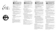
Electronic Connector <strong>Punch</strong>es<br />
RS-232, 229, 231, 234, 238.
Operation<br />
The 1/2" conduit-size punch is often used to increase<br />
the size of the pilot hole; this is called “step-up punching”.<br />
After enlarging the pilot hole, the 3/4" draw stud is<br />
used to punch the final hole. See steps 1-6.<br />
1. Drill 1/2" pilot hole using a Greenlee Kwik-Stepper ®<br />
step bit.<br />
2. Turn the release valve counterclockwise to<br />
make sure the ram is fully extended. Install 3/4" x<br />
3/8" adapter, 3/8" draw stud, spacer and 1/2"<br />
conduit die and insert into pilot hole.<br />
3. Thread 1/2" conduit punch onto the draw stud<br />
until the punch is tight. If punch is not tight, the<br />
hole will not be completed. Make sure the draw<br />
stud threads are fully engaged in the punch.<br />
<strong>7904SB</strong>/<strong>7906SB</strong> <strong>Hydraulic</strong> <strong>Punch</strong> <strong>Driver</strong><br />
4. Turn the release valve knob clockwise. Rotate<br />
driver to best operating position, and then pump<br />
lever handle until the punch is completely through<br />
the material. If the hole is not completed, check the<br />
setup described in steps 2 and 3.<br />
Do not operate the pump lever after the ram motion<br />
stops. Continuing to operate the pump lever after<br />
the ram motion stops will damage the driver and<br />
could propel internal parts with great force, striking<br />
nearby personnel.<br />
5. Release by turning release valve knob counterclockwise<br />
and remove the punch, die, draw stud and<br />
adapter.<br />
6. Install 3/4" draw stud and select proper size punch<br />
and die for desired size hole and repeat steps 4<br />
and 5.<br />
Greenlee Textron / Subsidiary of Textron Inc. 7 4455 Boeing Dr., Rockford, IL 61109-2988 815/397-7070
Operation (cont’d)<br />
<strong>7904SB</strong>/<strong>7906SB</strong> <strong>Hydraulic</strong> <strong>Punch</strong> <strong>Driver</strong><br />
Using the 29451 draw stud and optional 31874 step-saver adapter<br />
After drilling the pilot hole, use the 29451 draw stud<br />
and 31874 step-saver adapter as shown here. These<br />
components eliminate the need for step-up punching.<br />
Note: The stud and adapter are rated to drive the<br />
1-1/4" punch through 14 gauge mild steel.<br />
Do not exceed the rated capacity of the 29451 draw<br />
stud and 31874 step-saver adapter. Exceeding the<br />
maximum rated capacity could cause the stud and<br />
adapter to break and strike nearby personnel.<br />
1. Drill 1/2" pilot hole using Greenlee Kwik-Stepper ®<br />
step bit.<br />
2. Thread the adapter into the punch.<br />
3. Thread 7/16" draw stud tightly into driver. Place the<br />
die on the draw stud.<br />
4. Turn the release valve knob counterclockwise,<br />
to make sure the draw stud is fully extended.<br />
Insert stud through pilot hole.<br />
5. Thread the adapter with punch onto the draw<br />
stud until the punch is tight. If punch is not<br />
tight, the hole will not be completed.<br />
Greenlee Textron / Subsidiary of Textron Inc. 8 4455 Boeing Dr., Rockford, IL 61109-2988 815/397-7070
Operation (cont’d)<br />
<strong>7904SB</strong>/<strong>7906SB</strong> <strong>Hydraulic</strong> <strong>Punch</strong> <strong>Driver</strong><br />
Using the 29451 draw stud and optional 31874 step-saver adapter (cont’d)<br />
6. Make sure the draw stud threads are fully engaged<br />
in the adapter.<br />
7. Turn the release valve knob clockwise. Pump the<br />
handle until the punch is completely through the<br />
material. If the hole is not completed, check the<br />
setup described in steps 4 and 5.<br />
Do not operate the pump lever after the ram motion<br />
stops. Continuing to operate the pump lever after<br />
the ram motion stops will damage the driver and<br />
could propel internal parts with great force, striking<br />
nearby personnel.<br />
Note: If the ram motion stops before the hole is<br />
complete, verify that the setup is correct and<br />
that you have not exceeded the tool’s capacity.<br />
8. Release by turning the release valve knob<br />
counterclockwise.<br />
9. Remove punch and die.<br />
Greenlee Textron / Subsidiary of Textron Inc. 9 4455 Boeing Dr., Rockford, IL 61109-2988 815/397-7070
Maintenance<br />
Maintenance and repairs should be performed in a dust<br />
free area by qualified technicians.<br />
This unit requires minimum maintenance because it<br />
has a closed hydraulic system and all internal parts<br />
are lubricated by the hydraulic fluid. Lubricate lever pins<br />
lightly. Keep contaminants away from ram and cylinder.<br />
Store with handle down and hydraulic pressure released.<br />
Adding <strong>Hydraulic</strong> Oil<br />
1. Place driver in vise in vertical position with handles<br />
up. Unscrew reservoir handle (21) and remove<br />
bladder plug (20). Open release valve knob (27) to<br />
assure the ram is fully extended.<br />
2. Fill bladder (29) to point of overflow with Greenlee<br />
hydraulic oil.<br />
3. Purge air from system:<br />
Pump handle (22) several times to remove air from<br />
the pumping chamber. Close release valve knob<br />
and pump handle until ram (3) completes its full<br />
travel. Repeat as necessary.<br />
Note: Open release valve knob slowly so ram<br />
extends slowly. Rapid return of oil and<br />
air may cause oil to overflow the rubber<br />
bladder.<br />
If this procedure fails to remove air, remove bladder<br />
plug and open release valve knob. Place thumb<br />
over plug hole in bladder and squeeze bladder while<br />
pumping handle several times. Close the release<br />
valve knob and pump the handle until the ram<br />
completes its full travel. Repeat as necessary.<br />
If this procedure does not remove air, remove<br />
plunger (24) and fill plunger cavity with clean oil<br />
as outlined in Reassembly in the Maintenance<br />
section of this manual.<br />
4. Fill rubber bladder to the point of overflow and<br />
replace bladder plug. Wipe bladder clean of excess<br />
oil and reassemble reservoir handle.<br />
Troubleshooting And Repair<br />
To function properly, the punch driver must be free of<br />
oil leaks, must build oil pressure, and the ram section<br />
(right angle head) must rotate by hand force.<br />
Oil Leaks<br />
Check for external oil leaks.<br />
Check that release valve knob and stem are closed<br />
tightly and seating properly.<br />
Remove reservoir handle (21) and check for oil leaks<br />
around bladder (29) and bladder plug (20).<br />
<strong>7904SB</strong>/<strong>7906SB</strong> <strong>Hydraulic</strong> <strong>Punch</strong> <strong>Driver</strong><br />
Failure to Build Pressure<br />
Fill with oil and purge air from the system.<br />
See Adding <strong>Hydraulic</strong> Oil.<br />
Ram Section Will Not Rotate<br />
Loosen and readjust set screw (13). Hold punch driver<br />
with ram section down. Apply small amount of penetrating<br />
oil to cylinder (1) at the attachment point, then work<br />
ram section back and forth. Apply a small amount of<br />
SAE 30 oil to cylinder collar next to the pump block.<br />
Rebuilding<br />
If no leaks are visible and the unit will not build oil<br />
pressure, disassemble and rebuild the punch driver.<br />
Disassembly—Pump<br />
Note: Separate ram section from pump section.<br />
Remove set screw (13). Unscrew ram<br />
section from pump section.<br />
1. Remove reservoir handle (21), and bladder plug<br />
(20); drain oil from the bladder (29).<br />
2. Remove O-ring (35) and the bladder (29). Remove<br />
retaining rings (37) from one end of both handle<br />
pins (30) and remove handle pins and handle (22).<br />
3. Grasp plunger (24) with pliers; pull and twist to<br />
remove. Loosen set screw (12) from release valve<br />
knob (27); remove knob. Unscrew release stem (28)<br />
to remove from pump block (2). Remove retaining<br />
ring (41) and oil filter (40). Unscrew inlet check seat<br />
(23) and remove ball (32), and retaining ring (31).<br />
Unscrew jam screw (26). Remove spring (39)<br />
and ball (6).<br />
Disassembly—Ram<br />
Note: See illustration on the next page.<br />
1. Thread an installation rod into the tapped hole<br />
in ram (3). Place a flat washer and threaded<br />
hex nut on the installation rod. Tighten the nut until<br />
the spring retaining plate (4) is no longer applying<br />
force against the retaining rings (5).<br />
2. Remove the retaining rings (5) from the installation<br />
rod and remove the spring retaining plate (4) and<br />
compression spring (7).<br />
3. Screw a draw stud into end of ram (3); push the ram<br />
out of the cylinder (1).<br />
You have now disassembled the punch driver.<br />
Thoroughly clean all parts and inspect the three<br />
ball seats (intake, discharge and release stem)<br />
for nicks, scratches, or other damage.<br />
Greenlee Textron / Subsidiary of Textron Inc. 10 4455 Boeing Dr., Rockford, IL 61109-2988 815/397-7070
Maintenance (cont’d)<br />
Ball Seat Repair<br />
Re-seating:<br />
Minor seat imperfections may be corrected by<br />
re-seating. Use a soft brass rod and hammer to<br />
tap the ball against its seat.<br />
<strong>7904SB</strong>/<strong>7906SB</strong> <strong>Hydraulic</strong> <strong>Punch</strong> <strong>Driver</strong><br />
Wear eye protection when<br />
servicing this tool.<br />
Failure to wear eye protection can<br />
result in serious eye injury from<br />
flying debris or hydraulic oil.<br />
Re-drilling:<br />
Badly worn or damaged seats may be reworked by<br />
re-drilling and then re-seating.<br />
The pump block is manufactured with seats of 118˚ ,<br />
the standard drill point angle; use standard drills for<br />
re-drilling.<br />
• To re-drill the 7/32" ball seat for release stem (28):<br />
Use an “I” drill and a 9/64" diameter reamer.<br />
• To re-drill the 7/32" ball seat for the discharge check:<br />
Use an “I” drill and a 5/32" diameter reamer.<br />
• To re-drill the 3/16" ball seat for the intake check:<br />
Use a 1/4" drill and a 1/8" diameter reamer.<br />
When drilling; remove a minimum of material to obtain<br />
maximum seat life. Re-seat the balls before reassembly.<br />
“I” DRILL<br />
STD. DRILL<br />
ACCEPTABLE<br />
“I” DRILL<br />
RELEASE<br />
VALVE<br />
STEM<br />
“B” DRILL<br />
9/64" REAM<br />
DISCHARGE<br />
CHECK<br />
5/32" REAM<br />
9/64" REAM<br />
INTAKE<br />
CHECK<br />
Reassembly<br />
Reassembly is done in reverse sequence of disassembly.<br />
Inspect all O-ring seals for cuts and wear; replace as<br />
needed.<br />
Reassembly—Ram Section<br />
1. Lightly coat ram (3) and cylinder (1) seals, and both<br />
bores of the cylinder with clean oil.<br />
2. Push ram completely into cylinder.<br />
3. Thread installation rod into tapped hole in the ram<br />
and install compression spring (7). Place spring<br />
retaining plate (4) on top of spring (7) so the installation<br />
rod passes through the 1/4" hole in the<br />
retaining plate.<br />
4. Place a flat washer and thread a hex nut on the<br />
installation rod. Tighten the nut until spring retaining<br />
plate slides past the retaining ring groove. Install<br />
the two retaining rings (5) 180° apart. Remove<br />
installation rod.<br />
Installation<br />
Rod<br />
Installation Rod (Steel)<br />
Retaining Rings<br />
Flat Washer & Nut<br />
Spring Retaining Plate (4)<br />
Compression Spring (7)<br />
Cylinder (1)<br />
Ram (3)<br />
#10-32 Thread<br />
Greenlee Textron / Subsidiary of Textron Inc. 11 4455 Boeing Dr., Rockford, IL 61109-2988 815/397-7070<br />
3 1/ 2<br />
Reassembly—Pump Section<br />
Fill plunger (24) bore with clean hydraulic oil. Coat<br />
O-ring seals on plunger with clean oil and reinsert<br />
the pump block (2) with release valve knob (27) closed.
Maintenance (cont’d)<br />
Reassembly—Ram Section to Pump Section<br />
1. Install drive pin (25) to the pump block (2).<br />
Note: The drive pin must be installed to less<br />
than .100" high.<br />
2. Lightly coat the O-ring groove on the pump block<br />
and O-ring (14) with clean oil. Assemble O-ring (14)<br />
and back-up ring (15) to pump block (2).<br />
3. Apply a light coat of grease (Molycote G) to the<br />
external threads of pump block (2). Make sure the<br />
O-ring (14) and back-up ring (15) are lightly coated<br />
with oil, carefully slide the cylinder (1) onto the<br />
pump block.<br />
4. Thread the cylinder onto the pump block until it<br />
bottoms. Back off the cylinder until set screw (13)<br />
can be installed and still allow nearly 360° of<br />
rotation.<br />
Note: Repeat step 4 if cylinder is backed off<br />
more than ONE revolution.<br />
5. Apply Loctite 242 or equivalent to set screw (13)<br />
and install until set screw bottoms. Then back out<br />
1/8 to 1/4 turn.<br />
6. Fill unit with clean oil and purge air. See Adding<br />
<strong>Hydraulic</strong> Oil.<br />
Inspection and Adjustments<br />
After reassembly, check the following:<br />
Ram Travel Inspection<br />
Ram Extended<br />
With the draw stud removed and release valve knob<br />
open, observe whether end of ram (3) is flush to 1/64"<br />
(.396 mm) below the end of cylinder (1). If it is not, the<br />
bladder (29) contains too much oil.<br />
To remove excess oil:<br />
1. Remove reservoir handle (21) and bladder plug (20).<br />
2. Slowly open release valve knob (27); excess oil<br />
should come out of the bladder and the ram should<br />
move to become flush to 1/64" (.396 mm) below the<br />
end of the cylinder (1).<br />
3. If excess oil does not come out, replace the<br />
compression spring (7).<br />
Ram Retracted<br />
Measure ram travel distance (difference between<br />
ram completely extended and completely retracted).<br />
Distance is .830" (21.1 mm) to .930" (23.6 mm).<br />
<strong>7904SB</strong>/<strong>7906SB</strong> <strong>Hydraulic</strong> <strong>Punch</strong> <strong>Driver</strong><br />
Pump Section Inspection<br />
Intake Check Valve<br />
Close the release valve knob and operate handle (22)<br />
until ram (3) bottoms and handle resistance increases.<br />
• If the ram bottoms in 30 strokes or less, the inlet<br />
check valve (32 and 23) is operating properly.<br />
• More than 30 strokes indicates an inlet check leak.<br />
Re-seat, re-drill or replace the inlet check seat (23).<br />
Discharge Check Valve<br />
If the handle (22) returns to the raised position by itself,<br />
the discharge check valve is leaking. Re-seat or re-drill<br />
the discharge check seat and replace the compression<br />
spring (39).<br />
Install socket screw (26) to depth shown. If screw is<br />
bottomed out, ball cannot move and quick draw handle<br />
will not pump.<br />
Release Valve<br />
Pump the handle until the ram bottoms. Gently apply<br />
and maintain additional force on handle (22). If the<br />
handle remains solid, the ball (32) is operating properly.<br />
If the handle (22) goes down slowly, the release valve is<br />
leaking. Re-seat or re-drill the release stem seat and<br />
replace O-ring (33).<br />
Cylinder Rotation<br />
Install a 3/4" draw stud and a 2" conduit size punch and<br />
die to the punch driver. Hold the driver by the reservoir<br />
handle (21) so the draw stud is horizontal; the cylinder<br />
should not rotate from the combined weight of the draw<br />
stud, the punch and the die. If rotation occurs, O-ring<br />
(14) may be worn.<br />
If binding or roughness occurs during cylinder rotation,<br />
check for lubrication or damage at threads closest to set<br />
screw (13); also check adjustment of set screw (13).<br />
Greenlee Textron / Subsidiary of Textron Inc. 12 4455 Boeing Dr., Rockford, IL 61109-2988 815/397-7070<br />
1.675<br />
Socket Screw<br />
#26<br />
.05<br />
Approx.
Troubleshooting<br />
<strong>7904SB</strong>/<strong>7906SB</strong> <strong>Hydraulic</strong> <strong>Punch</strong> <strong>Driver</strong><br />
PROBLEM PROBABLE CAUSE POSSIBLE REMEDY<br />
Will not punch hole. Improper assembly or use of punch, See Operating Instructions and<br />
die or accessories. Capacity Chart.<br />
Low oil level. See Adding <strong>Hydraulic</strong> Oil<br />
in Maintenance Section.<br />
Requires excessive lever force. Improper assembly or use of punch, See Operating Instructions and<br />
die or accessories. Capacity Chart.<br />
Material being punched is too thick or<br />
too hard. See Capacity Chart.<br />
Pump will not build pressure. Air in system. See step 3, Adding <strong>Hydraulic</strong> Oil.<br />
Excessive number of strokes Inoperative intake check valve. See Inspection and Adjustments,<br />
strokes are required to punch Intake Check Valve Inspection.<br />
hole.<br />
Inoperative discharge check valve. See Inspection and Adjustments,<br />
Discharge Check Valve Inspection.<br />
Leaking Release Valve. See Inspection and Adjustments,<br />
Release Valve Inspection.<br />
Damaged piston, piston extension, See Maintenance and Repairs,<br />
pump plunger seals or mating surfaces. Cylinder and Pump Block sections.<br />
Clogged filter. Clean or replace<br />
filter (40).<br />
Will not return piston. Weak or damaged return spring, See Piston Travel Inspection.<br />
excess oil in unit.<br />
External oil leaks. Damaged seals or surfaces. Damaged piston, piston extension,<br />
pump plunger seals or mating surfaces.<br />
See Troubleshooting and Repair,<br />
Cylinder and Pump Block sections.<br />
Damaged Release Valve Stem seal.<br />
See Inspection and Adjustments,<br />
Release Valve Inspection.<br />
Greenlee Textron / Subsidiary of Textron Inc. 13 4455 Boeing Dr., Rockford, IL 61109-2988 815/397-7070
<strong>7904SB</strong>/<strong>7906SB</strong> <strong>Hydraulic</strong> <strong>Punch</strong> <strong>Driver</strong><br />
Greenlee Textron / Subsidiary of Textron Inc. 14 4455 Boeing Dr., Rockford, IL 61109-2988 815/397-7070
INSTRUCTION MANUAL<br />
<strong>7904SB</strong>/<strong>7906SB</strong><br />
QUICK DRAW 90 <br />
HYDRAULISCHE STANZMASCHINE<br />
Für Einheiten mit Seriencode “ZA”<br />
Vor Bedienung und Wartung dieses Gerätes bitte<br />
alle Instruktionen und Sicherheitsinformationen der<br />
Anleitung genau lesen und beachten.<br />
999 0373.3 © 2000 Greenlee Textron IM 1125 REV 6 11/00
Inhaltsverzeichnis<br />
Beschreibung ............................................................... 16<br />
Wichtige Sicherheitshinweise .................................17-18<br />
Spezifikationen ............................................................ 19<br />
Leistung und Auswahl der Zugbolzen ......................... 20<br />
Betrieb .....................................................................21-23<br />
Wartung ..................................................................24-28<br />
Fehlerbehandlung ...................................................29-30<br />
Explosionszeichnung ................................................... 31<br />
Teileliste ....................................................................... 32<br />
Zugbolzen und Zubehör............................................... 33<br />
Beschreibung<br />
Quick Draw 90 ist eine in sich geschlossene<br />
hydraulische Stanzmaschine. Quick Draw 90 und<br />
Greenlee-Stempel, -Schneideisen und -Zugbolzen<br />
bilden ein komplettes System zum Stanzen von Löchern<br />
verschiedener Formen und Größen in weichem Stahl,<br />
Aluminium, Fiberglas und Plastik. Slug-Splitter ® -<br />
Stempel, -Schneideisen und -Bolzen eignen sich zum<br />
Stanzen aller dieser Materialien und rostfreien Stahls.<br />
Es sind verschiedene Quick Draw-Ausstattungen lieferbar:<br />
<strong>7904SB</strong> Quick Draw Hydraulische Stanzmaschine, Zugbolzen<br />
<strong>7906SB</strong> Quick Draw Hydraulische Stanzmaschine, Zugbolzen,<br />
Rohrstempel und -schneideisen<br />
7904E Quick Draw Hydraulische Stanzmaschine und<br />
Zugbolzen<br />
7904ESB Quick Draw Hydraulische Stanzmaschine, Zugbolzen,<br />
Pg-Stempel und -schneideisen<br />
7904ISO Quick Draw Hydraulische Stanzmaschine, Zugbolzen,<br />
ISO-Stempel und -schneideisen<br />
<strong>7904SB</strong>/<strong>7906SB</strong> Hydraulische Stanzmaschine<br />
Sicherheitsvorkehrungen<br />
Sicherheitsvorkehrungen sind bei der Verwendung und<br />
der Wartung der Geräte und Ausrüstung von Greenlee<br />
Fairmont entscheidend. Die vorliegende Anleitung und<br />
etwaige an den Maschinen angebrachte Etiketten<br />
geben Hinweise zur Vermeidung von Gefahren und<br />
gefährlichen Praktiken in bezug auf die Handhabung<br />
dieses Gerätes. Bitte alle hier angegebenen<br />
Sicherheitshinweise beachten.<br />
Zweck<br />
Dieses Handbuch soll dazu dienen, das Personal mit<br />
den sicheren Betriebs- und Wartungsverfahren der<br />
folgenden Hydraulik-Schlagschrauber von Greenlee<br />
Fairmont vertraut zu machen:<br />
Hydraulische Stanzmaschine<br />
Bitte dieses Handbuch allen Mitarbeitern zugänglich<br />
machen.<br />
Ersatz-Handbücher sind auf Anfrage kostenlos<br />
erhältlich.<br />
und sind eingetragene<br />
Warenzeichen der Firma Greenlee Textron.<br />
DIESES HANDBUCH BITTE AUFBEWAHREN<br />
Greenlee Textron/Tochtergesellschaft von Textron Inc. 16 4455 Boeing Dr., Rockford, IL 61109-2988 815/397-7070
<strong>7904SB</strong>/<strong>7906SB</strong> Hydraulische Stanzmaschine<br />
WICHTIGE SICHERHEITSHINWEISE<br />
SICHERHEITS-<br />
ALARM<br />
SYMBOL<br />
Dieses Symbol dient dazu, Aufmerksamkeit auf<br />
Gefahren bzw. Auf unsichere Praktiken zu lenken,<br />
die Verletzungen oder Sachschäden hervorrufen<br />
könnten. Die im Hinweis enthaltenen, im folgenden<br />
näher definierten Worte geben den Schweregrad der<br />
Gefahr an. Die auf das betreffende Wort folgende<br />
Erklärung Informationen über die Vermeidung oder<br />
Verhinderung der Gefahr.<br />
Unmittelbare Gefahr, die, falls nicht vermieden, zu<br />
schweren Personenverletzungen oder zum Tod<br />
führen WIRD.<br />
Gefahrenquellen oder unsichere Praktiken, die, falls<br />
nicht vermieden, zu schweren Personenverletzungen<br />
oder zum Tod führen KÖNNTEN.<br />
Gefahrenquellen oder unsichere Praktiken, die, falls<br />
nicht vermieden, zu Personenverletzungen oder<br />
Sachschäden führen KÖNNTEN.<br />
Eine Person, die zuvor nicht alle<br />
Anleitungen gelesen und verstanden<br />
hat, ist für die Bedienung dieses<br />
Werkzeugs nicht qualifiziert.<br />
Fehlendes Verständnis der<br />
Sicherheitsaspekte und -anleitungen<br />
kann zu schweren Verletzungen oder<br />
sogar zum Tod führen.<br />
Greenlee Textron/Tochtergesellschaft von Textron Inc. 17 4455 Boeing Dr., Rockford, IL 61109-2988 815/397-7070
<strong>7904SB</strong>/<strong>7906SB</strong> Hydraulische Stanzmaschine<br />
WICHTIGE SICHERHEITSHINWEISE<br />
Stromschlaggefahr:<br />
Das Gerät nicht in der Nähe von<br />
Stromkreisen betreiben. Ein Kontakt<br />
mit Stromkreisen kann zu schweren<br />
Verletzungen oder zum Tod führen.<br />
• Die Nennleistung des Werkzeugs darf nicht<br />
überschritten werden. Ein Überschreiten der<br />
Nennleistung könnte zum Bruch des Werkzeugs<br />
oder von Komponenten führen und in der Nähe<br />
befindliche Personen verletzen.<br />
• Keine Verlängerungen oder Umgehungsadapter<br />
an den Griffen anbringen. Die Verwendung von<br />
Umgehungsadaptern oder die Anwendung von<br />
mehr als 356 N (80 pounds) an den Griffen<br />
beschädigt die Stanzmaschine und kann dazu<br />
führen, daß interne Teile mit großer Kraft<br />
herausgeschleudert werden und in der Nähe<br />
befindliche Personen verletzen.<br />
• Darauf achten, daß sich niemand direkt vor dem<br />
Stempel aufhält. Ein Versagen der Komponenten<br />
könnte den Stempel und Zugbolzen mit großer<br />
Kraft herausschleudern und in der Nähe<br />
befindliche Personen verletzen.<br />
• Nur Greenlee-Stempel, -Schneideisen und -<br />
Zugbolzen verwenden. Andere Stempel,<br />
Schneideisen und Zugbolzen halten unter<br />
Umständen die Belastungen der Stanzmaschine<br />
nicht aus. Sie könnten brechen und in der Nähe<br />
befindliche Personen verletzen.<br />
Beim Betrieb dieses Werkzeugs<br />
Augenschutz tragen.<br />
Die Mißachtung der<br />
Augenschutzvorschrift kann,<br />
verursacht durch herumfliegendes<br />
Material oder Hydrauliköl, zu<br />
schweren Augenverletzungen führen.<br />
Den Pumpenhebel nicht mehr betätigen, nachdem<br />
die Stanzbewegung beendet ist. Das Betätigen des<br />
Pumpenhebels, nachdem die Stanzbewegung<br />
beendet ist, beschädigt die Stanzmaschine und<br />
kann dazu führen, daß interne Teile mit großer Kraft<br />
herausgeschleudert werden und in der Nähe<br />
befindliche Personen verletze.<br />
• Das Werkzeug auf Verschleiß und<br />
Beschädigungen prüfen. Verschlissene,<br />
beschädigte oder fehlende Komponenten mit<br />
Greenlee-Ersatzteilen ersetzen. Ein beschädigtes<br />
oder nicht vorschriftsgemäß zusammengesetztes<br />
Werkzeug kann brechen und in der Nähe<br />
befindliche Personen mit einer Wucht treffen, die<br />
zu schweren Verletzungen oder sogar zum Tod<br />
führen kann.<br />
• Stempel, Schneideisen, Zugbolzen und<br />
Distanzstücke auf Verschleiß und<br />
Beschädigungen prüfen. Verschlissene oder<br />
beschädigte Teile mit Greenlee-Ersatzteilen<br />
ersetzen. Stempel, die stumpfe Schneidflächen<br />
aufweisen, sind zu ersetzen.<br />
Dieses Werkzeug nur für den vom Hersteller<br />
vorgesehenen Zweck verwenden. Eine Nutzung,<br />
die von dem in diesem Handbuch beschriebenen<br />
Zwecken abweicht, kann zu Verletzungen oder<br />
Sachschaden führen.<br />
Greenlee Textron/Tochtergesellschaft von Textron Inc. 18 4455 Boeing Dr., Rockford, IL 61109-2988 815/397-7070
Spezifikationen<br />
<strong>7904SB</strong>/<strong>7906SB</strong> Hydraulische Stanzmaschine<br />
Mechanische Daten<br />
Gewicht ....................................................................................................... 7,4 lbs.<br />
Gesamtabmessungen:<br />
Länge ................................................................................................ 12,75 Zoll<br />
Maximalkraft am Griff................................................................................... 80 lbs.<br />
Hub (Maximum) ............................................0,85 Zoll/min. Zugbolzenwegstrecke<br />
Maximale Zugbolzen-Nennkraft ............................................................ 16 000 lbs.<br />
Max. Stempeldurchmesser und Materialstärke ................. Siehe Leistungstabelle<br />
Hydraulikdaten<br />
Max. Betriebsnenndruck ....................................................................... 10 000 lbs.<br />
Gesamtbetriebsvolumen (Kubikzoll) ............................................................2,0735<br />
Volumen/Hub (Kubikzoll/Zoll) ......................................................................0,0525<br />
Kreislaufkapazität (Kubikzoll) ........................................................... Gesamt: 3,50<br />
Tank: 2,32<br />
Dichtungen .................................... Nitril-, Fluorkohlenstoff- und Teflon-Stützringe<br />
Flüssigkeitsverträglichkeit: Verträglich mit Nitril- (Buna N) und Fluorkohlenstoff-<br />
(Viton) Dichtungsmaterialien, die sich für<br />
Hydrauliköle, Ölemulsionen, synthetische<br />
Öle und Wasser eignen.<br />
Kreislauftyp ........................................................................................ Geschlossen<br />
Empfohlene Flüssigkeit.........................................................Greenlee-Hydrauliköl<br />
Sonstiges<br />
Betriebstemperatur ................................................. 12°C (10°F) bis 43°C (110°F)<br />
Betriebslage ................................................................................... Keine Auflagen<br />
Greenlee Textron/Tochtergesellschaft von Textron Inc. 19 4455 Boeing Dr., Rockford, IL 61109-2988 815/397-7070
Leistung und Auswahl der Zugbolzen<br />
(1" = 1 Zoll = 25,4 mm)<br />
12345<br />
12345<br />
12345<br />
12345<br />
12345<br />
12345<br />
12345<br />
1234<br />
1234<br />
1234<br />
1234<br />
1234<br />
14 Ga. (1,9 mm [0,0747"])<br />
Weicher Stahl<br />
10 Ga. (3,4 mm [0,1345"])<br />
Weicher Stahl<br />
Bolzen und Zubehör<br />
1614SS<br />
ZUGBOLZEN<br />
1924AA<br />
DISTANZSTÜCK<br />
31874<br />
ADAPTER<br />
(OPTION)<br />
1924AA<br />
DISTANZSTÜCK<br />
1924AA<br />
DISTANZSTÜCK<br />
31872<br />
3/4" ZUGBOLZEN<br />
33967<br />
ADAPTER<br />
<strong>7904SB</strong>/<strong>7906SB</strong> Hydraulische Stanzmaschine<br />
123456<br />
123456<br />
123456<br />
123456<br />
33967 123456<br />
ADAPTER<br />
Siehe Hinweis ➁<br />
29451<br />
7/16" ZUGBOLZEN<br />
Siehe Hinweis ➁<br />
29451<br />
7/16" ZUGBOLZEN<br />
31872<br />
3/4" ZUGBOLZEN<br />
123<br />
123<br />
123<br />
123<br />
Standard- u. Slug-Buster ® -Stempel Slug-Splitter ®<br />
1/2" 3/4" 1-7/32" 1" 1-1/4" 1-1/2" 2" 1/2" 3/4"<br />
Anschl. Anschl. Anschl. Anschl. Anschl. Anschl. Anschl. Anschl.<br />
Ø 0.885" Ø 1.115" Ø 1.362" Ø 1.701" Ø 1.951" Ø 2.416" Ø 0.885" Ø 1.115"<br />
15,2 mm 28,3 mm 34,6 mm 43,2 mm 49,6 mm 61,5 mm 15,2 mm 28,3 mm<br />
12345678901234567890123456789<br />
12345678901234567890123456789<br />
Siehe Hinweis ➀<br />
12345678901234567890123456789<br />
12345678901234567890123456789<br />
12345678901234567890123456789<br />
12345678901234567890123456789<br />
12345678901234567890123456789<br />
12345678901234567890123456789<br />
1234567890123456789012<br />
1234567890123456789012<br />
1234567890123456789012<br />
1234567890123456789012<br />
1234567890123456789012<br />
10 Ga. (3,4 mm [0,1345"])<br />
Rostfreier Stahl<br />
16 Ga. (1,5 mm [0,0598"])<br />
Weicher Stahl und 1/18" weiches Aluminium<br />
12345678901<br />
12345678901<br />
12345678901<br />
12345678901<br />
12345678901<br />
12345678901<br />
1234<br />
1234<br />
1234<br />
1234<br />
1-7/32" 1" 1-1/4"<br />
Anschl. Anschl.<br />
Ø 1.362" Ø 1.701"<br />
34,6 mm 43,2 mm<br />
123456789012345<br />
123456789012345<br />
123456789012345<br />
123456789012345<br />
➀ Bei Verwendung dieses Adapters können die Slug-Buster ® -Stempel das Werkstück, wegen des kleineren<br />
Führungslochs, unter Umständen nicht durchspalten.<br />
➁ Der Stufenspar-Adapter 31874 und der Zugbolzen 29451 sind nur in der Ausstattung 7804SB enthalten.<br />
Diese Teile können auch separat erworben und mit jeder anderen Quick-Draw-Ausstattung eingesetzt werden.<br />
Greenlee Textron/Tochtergesellschaft von Textron Inc. 20 4455 Boeing Dr., Rockford, IL 61109-2988 815/397-7070<br />
Stempel für elektronische Anschlüsse:<br />
RS-232, -229, -231, -234, -238.
Betrieb<br />
Der 1/2-Zoll-Rohrstempel wird oft verwendet, um die<br />
Größe des Führungslochs zu erhöhen (stufenweises<br />
Aufwärtsstanzen). Nach der Vergrößerung des<br />
Führungslochs wird der 3/4-Zoll-Zugbolzen verwendet, um<br />
das endgültige Loch zu stanzen. Siehe Schritte 1 bis 6.<br />
1. Mit einem Greenlee Kwik-Stepper ® -Stufenbohrer ein<br />
1/2-Zoll-Führungsloch bohren.<br />
2. Das Löseventil entgegen dem Uhrzeigersinn<br />
drehen, um sicherzustellen, daß der Zugbolzen<br />
vollständig ausgefahren ist. Den 3/4- x 3/8-Zoll-<br />
Adapter, den 3/8-Zoll-Zugbolzen, das Distanzstück<br />
und das 1/2-Zoll-Rohrschneideisen installieren und<br />
in das Führungsloch einführen.<br />
3. Den 1/2-Zoll-Rohrstempel auf den Zugbolzen<br />
schrauben, bis der Stempel festsitzt. Wenn der<br />
Stempel nicht festsitzt, kann das Loch nicht<br />
vollendet werden. Sicherstellen, daß das<br />
Zugbolzengewinde vollständig im Stempel<br />
eingedreht ist.<br />
<strong>7904SB</strong>/<strong>7906SB</strong> Hydraulische Stanzmaschine<br />
4. Den Löseventilknopf im Uhrzeigersinn drehen. Die<br />
Stanzmaschine in die optimale Betriebsposition<br />
drehen. Dann mit dem Hebelgriff pumpen, bis sich<br />
der Stempel vollständig durch das Material<br />
gearbeitet hat. Wenn das Loch nicht vollendet wird,<br />
überprüfen Sie erneut die in Schritte 2 und 3<br />
beschriebenen Einstellungen.<br />
Den Pumpenhebel nicht mehr betätigen, nachdem<br />
die Stanzbewegung beendet ist. Das Betätigen des<br />
Pumpenhebels, nachdem die Stanzbewegung<br />
beendet ist, beschädigt die Stanzmaschine und<br />
kann dazu führen, daß interne Teile mit großer Kraft<br />
herausgeschleudert werden und in der Nähe<br />
befindliche Personen verletzen.<br />
5. Werkzeug durch Drehen des Löseventilknopfs<br />
entgegen dem Uhrzeigersinn lösen. Stempel,<br />
Schneideisen, Zugbolzen und Adapter abnehmen.<br />
6. Den 3/4-Zoll-Zugbolzen installieren, die für die<br />
gewünschte Lochgröße geeigneten Stempel und<br />
Schneideisen auswählen, und die Schritte 4 und 5<br />
wiederholen.<br />
Greenlee Textron/Tochtergesellschaft von Textron Inc. 21 4455 Boeing Dr., Rockford, IL 61109-2988 815/397-7070
<strong>7904SB</strong>/<strong>7906SB</strong> Hydraulische Stanzmaschine<br />
Betrieb (fortgesetzt)<br />
Unter Verwendung des Zugbolzens 29451 und des wahlfreien Stufenspar-Adapters 31874<br />
Nach dem Bohren des Führungslochs den Zugbolzen<br />
29451 und den Stufenspar-Adapter 31874, wie hier<br />
abgebildet, verwenden. Diese Komponenten machen<br />
stufenweises Aufwärtsstanzen unnötig.<br />
Hinweis: Der Zugbolzen und der Adapter eignen sich<br />
für das Stanzen mit dem 1 1/4-Zoll-Stempel<br />
durch 14 Gauge weichen Stahl.<br />
Die Nennleistungen des Zugbolzen 29451 und des<br />
Stufenspar-Adapters 31874 dürfen nicht überschritten<br />
werden. Das Überschreiten der maximal zugelassenen<br />
Werte kann zum Bruch des Zugbolzens und Adapters<br />
führen und in der Nähe befindliche Personen verletzen.<br />
1. Mit einem Greenlee Kwik-Stepper ® -Stufenbohrer ein<br />
1/2-Zoll-Führungsloch bohren.<br />
2. Den Adapter in den Stempel einschrauben.<br />
3. Den 7/16-Zoll-Zugbolzen fest in die Stanzmaschine<br />
einschrauben. Das Schneideisen auf den<br />
Zugbolzen schieben.<br />
4. Den Löseventilknopf entgegen dem<br />
Uhrzeigersinn drehen, um sicherzustellen, daß<br />
der Zugbolzen vollständig ausgefahren ist. Den<br />
Bolzen durch das Führungsloch einführen.<br />
5. Den Adapter mit dem Stempel auf den Zugbolzen<br />
schrauben, bis der Stempel festsitzt. Wenn der<br />
Stempel nicht festsitzt, kann das Loch nicht<br />
vollendet werden.<br />
Greenlee Textron/Tochtergesellschaft von Textron Inc. 22 4455 Boeing Dr., Rockford, IL 61109-2988 815/397-7070
<strong>7904SB</strong>/<strong>7906SB</strong> Hydraulische Stanzmaschine<br />
Betrieb (fortgesetzt)<br />
Unter Verwendung des Zugbolzens 29451 und des wahlfreien Stufenspar-Adapters 31874 (fortgesetzt)<br />
6. Sicherstellen, daß das Zugbolzengewinde<br />
vollständig im Adapter eingedreht ist.<br />
7. Den Löseventilknopf im Uhrzeigersinn drehen. Mit<br />
dem Hebelgriff pumpen, bis sich der Stempel<br />
vollständig durch das Material gearbeitet hat. Wenn<br />
das Loch nicht vollendet wird, überprüfen Sie erneut<br />
die in Schritte 4 und 5 beschriebenen Einstellungen.<br />
Den Pumpenhebel nicht mehr betätigen, nachdem<br />
die Stanzbewegung beendet ist. Das Betätigen des<br />
Pumpenhebels, nachdem die Stanzbewegung<br />
beendet ist, beschädigt die Stanzmaschine und<br />
kann dazu führen, daß interne Teile mit großer Kraft<br />
herausgeschleudert werden und in der Nähe<br />
befindliche Personen verletzen.<br />
Hinweis: Falls die Stanzbewegung anhält, bevor das<br />
Loch vollendet ist, muß überprüft werden, ob<br />
die gesamte Einrichtung vorschriftsgemäß ist<br />
und die Nennleistung des Werkzeugs nicht<br />
überschritten wurde.<br />
8. Werkzeug durch Drehen des Löseventilknopfs<br />
entgegen dem Uhrzeigersinn lösen.<br />
9. Stempel und Schneideisen abnehmen.<br />
Greenlee Textron/Tochtergesellschaft von Textron Inc. 23 4455 Boeing Dr., Rockford, IL 61109-2988 815/397-7070
Wartung<br />
Wartungs- und Reparaturarbeiten sollten durch<br />
qualifizierte Techniker in einer staubfreien Umgebung<br />
durchgeführt werden.<br />
Diese Einheit erfordert nur minimale Wartung, da sie<br />
über ein geschlossenes Hydrauliksystem verfügt und<br />
alle internen Teile durch die Hydraulikflüssigkeit<br />
geschmiert werden. Die Hebelstifte leicht schmieren.<br />
Fremdstoffe von Stößel und Zylinder fernhalten.<br />
Werkzeug mit Griff nach unten und abgelassenem<br />
Hydraulikdruck lagern.<br />
Hinzufügen von Hydrauliköl<br />
1. Die Stanzmaschine vertikal mit nach oben<br />
gerichteten Griffen in einen Schraubstock spannen.<br />
Den Tankgriff (21) abschrauben und den<br />
Speicherstopfen (20) entfernen. Den<br />
Löseventilknopf (27) aufdrehen, um sicherzustellen,<br />
daß der Stößel vollständig ausgefahren ist.<br />
2. Den Speicher (29) bis zur Überlaufmarke mit<br />
Greenlee-Hydrauliköl füllen.<br />
3. System entlüften:<br />
Mit dem Griff (22) mehrmals pumpen, um Luft aus<br />
der Pumpkammer zu entfernen. Den<br />
Löseventilknopf zudrehen und mit dem Griff<br />
pumpen, bis der Stößel (3) eine ganze Wegstrecke<br />
zurückgelegt hat. So oft wie nötig wiederholen.<br />
Hinweis: Den Löseventilknopf langsam aufdrehen,<br />
so daß der Stößel langsam ausfährt.<br />
Schneller Rückfluß von Öl und Luft kann<br />
dazu führen, daß das Öl beim Speicher<br />
überläuft.<br />
Falls dieses Verfahren nicht zur Entlüftung führt,<br />
den Speicherstopfen entfernen und den<br />
Löseventilknopf aufdrehen. Einen Daumen auf das<br />
Stopfenloch des Speichers drücken, den Speicher<br />
auspressen und gleichzeitig mit dem Griff mehrmals<br />
pumpen. Den Löseventilknopf zudrehen und mit<br />
dem Griff pumpen, bis der Stößel eine ganze<br />
Wegstrecke zurückgelegt hat. So oft wie nötig<br />
wiederholen.<br />
Falls dieses Verfahren nicht zur Entlüftung führt,<br />
den Tauchkolben (24) entfernen und die<br />
Tauchkolben-Aussparung mit sauberem Öl befüllen<br />
(gemäß Beschreibung unter Zusammenbau im<br />
Wartungsabschnitt dieses Handbuchs).<br />
4. Den Speicher bis zur Überlaufmarke füllen. Den<br />
Speicherstopfen wieder einsetzen. Überschüssiges<br />
Öl vom Speicher abwischen. Den Tankgriff wieder<br />
installieren.<br />
<strong>7904SB</strong>/<strong>7906SB</strong> Hydraulische Stanzmaschine<br />
Fehlerbehandlung und Reparatur<br />
Für ordnungsgemäßes Funktionieren muß die<br />
Stanzmaschine frei von Öllecks sein und einen Öldruck<br />
bilden können. Zudem muß sich der Stößelabschnitt<br />
(rechtwinkliger Kopf) mit der Hand drehen lassen.<br />
Öllecks<br />
Auf äußere Öllecks überprüfen.<br />
Prüfen, ob der Löseventilknopf und die Kolbenstange<br />
fest zugedreht/angezogen sind und gut sitzen.<br />
Den Tankgriff (21) entfernen. Die Bereiche um den<br />
Speicher (29) und Speicherstopfen (20) herum auf<br />
Öllecks überprüfen.<br />
Kein Druck<br />
System entlüften. Öl auffüllen.<br />
Siehe unter Hinzufügen von Hydrauliköl.<br />
Stößelabschnitt dreht nicht<br />
Die Einstellschraube (13) lösen und neu einstellen. Die<br />
Stanzmaschine mit dem Stößelabschnitt nach unten<br />
halten. Ein wenig Kriechöl am Befestigungspunkt des<br />
Zylinders (1) anbringen, dann den Stößelabschnitt hin<br />
und her bewegen. Ein wenig SAE 30-Öl am<br />
Zylinderhals neben dem Pumpenblock anbringen.<br />
Überarbeitung<br />
Falls keine Lecks sichtbar sind, das Gerät jedoch<br />
keinen Öldruck bildet, die Stanzmaschine zerlegen und<br />
wieder zusammenbauen.<br />
Greenlee Textron/Tochtergesellschaft von Textron Inc. 24 4455 Boeing Dr., Rockford, IL 61109-2988 815/397-7070
Wartung (fortgesetzt)<br />
Zerlegen der Pumpe<br />
Hinweis: Den Stößelabschnitt vom<br />
Pumpenabschnitt trennen. Die<br />
Einstellschraube (13) entfernen. Den<br />
Stößelabschnitt vom Pumpenabschnitt<br />
abschrauben.<br />
1. Tankgriff (21) und Speicherstopfen entfernen. Das<br />
Öl vom Speicher (29) ablassen.<br />
2. O-Ring (35) und Speicher (29) entfernen. Die<br />
Sicherungsringe (37) von jeweils einem Ende der<br />
beiden Griffstifte (30) entfernen. Die Griffstifte und<br />
den Griff (22) abnehmen.<br />
3. Den Tauchkolben (24) mit einer Zange festhalten<br />
und durch Ziehen und Drehen lösen und<br />
herausnehmen. Die Einstellschraube (12) am<br />
Löseventilknopf (27) lösen und den Knopf<br />
abnehmen. Die Lösekolbenstange (28) vom<br />
Pumpenblock (2) abschrauben. Sicherungsring (41)<br />
und Ölfilter (40) abnehmen. Das<br />
Einlaßabsperrauflager (23) abschrauben. Kugel (32)<br />
und Sicherungsring (31) entfernen. Die<br />
Gegenschraube (26) abschrauben. Feder (39) und<br />
Kugel (6) entfernen.<br />
<strong>7904SB</strong>/<strong>7906SB</strong> Hydraulische Stanzmaschine<br />
Zerlegen des Stößels<br />
Hinweis: Siehe Abbildung auf der nächsten Seite.<br />
1. Eine Installationsstange in das Gewindeloch des<br />
Stößels (3) einschrauben. Eine flache Scheibe und<br />
eine Sechskantmutter mit Gewinde auf die<br />
Installationsstange aufsetzen. Die Mutter<br />
aufschrauben, bis die federbelastete Halteplatte (4)<br />
keinen Druck mehr auf die Sicherungsringe (5)<br />
ausübt.<br />
2. Die Sicherungsringe (5) von der Installationsstange<br />
entfernen. Die federbelastete Halteplatte (4) und die<br />
Kompressionsfeder (7) abnehmen.<br />
3. Einen Zugbolzen in das Stößelende (3)<br />
einschrauben. Den Stößel aus dem Zylinder (1)<br />
heraus drücken.<br />
Die Stanzmaschine ist nun vollständig zerlegt. Alle<br />
Teile gründlich reinigen. Die drei Kugelauflager<br />
(Einlaß, Abfluß und Lösekolbenstange) auf<br />
Einkerbungen, Kratzer oder andere Schäden<br />
überprüfen.<br />
Greenlee Textron/Tochtergesellschaft von Textron Inc. 25 4455 Boeing Dr., Rockford, IL 61109-2988 815/397-7070
Wartung (fortgesetzt)<br />
Reparatur des Kugelauflagers<br />
Neusetzen:<br />
Geringfügige Mängel am Sitz können durch Neusetzen<br />
korrigiert werden. Die Kugel mit einem Stift aus<br />
weichem Messing und einem Hammer gegen das<br />
Auflager klopfen.<br />
Nachbohren:<br />
Stark verschlissene oder beschädigte Auflager können<br />
durch Nachbohren und Neusetzen der Kugel erneuert<br />
werden.<br />
Der Pumpenblock wurde mit Auflagern von 118°<br />
(Standard-Bohrungswinkel) hergestellt. Zum<br />
Nachbohren Standardbohrer verwenden.<br />
• Zum Nachbohren des 7/32-Zoll-Kugelauflagers der<br />
Lösekolbenstange einen “I”-Bohrer und eine Reibahle<br />
mit 9/64 Zoll Durchmesser verwenden.<br />
• Zum Nachbohren des 7/32-Zoll-Kugelauflagers der<br />
Abflußsperre einen “I”-Bohrer und eine Reibahle mit<br />
5/32 Zoll Durchmesser verwenden.<br />
• Zum Nachbohren des 3/16-Zoll-Kugelauflagers der<br />
Einlaßsperre einen 1/4-Zoll-Bohrer und eine Reibahle<br />
mit 1/8 Zoll Durchmesser verwenden.<br />
Zur Gewährleitung einer optimalen Lebensdauer der<br />
Auflager beim Bohren ein Minimum an Material<br />
entfernen. Die Kugeln vor dem Zusammenbau wieder<br />
einsetzen.<br />
<strong>7904SB</strong>/<strong>7906SB</strong> Hydraulische Stanzmaschine<br />
Bei der Wartungsarbeiten an<br />
diesem Werkzeug einen<br />
Augenschutz tragen.<br />
Die Mißachtung der<br />
Augenschutzvorschrift kann,<br />
verursacht durch herumfliegendes<br />
Material oder Hydrauliköl, zu<br />
schweren Augenverletzungen<br />
führen.<br />
“I”-BOHRER<br />
STANDARDBOHRER<br />
AKZEPTABEL<br />
“I”-BOHRER<br />
LÖSEVENTILKOLBENSTANGE<br />
“B”-BOHRER<br />
9/64-ZOLL-AUSRÄUMUNG<br />
ABFLUSS<br />
5/32-ZOLL-AUSRÄUMUNG<br />
9/64-ZOLL-AUSRÄUMUNG<br />
EINLASS<br />
Greenlee Textron/Tochtergesellschaft von Textron Inc. 26 4455 Boeing Dr., Rockford, IL 61109-2988 815/397-7070
Wartung (fortgesetzt)<br />
Zusammenbau<br />
Beim Zusammenbau werden die Zerlegungsschritte in<br />
umgekehrter Reihenfolge ausgeführt.<br />
Alle O-Ring-Dichtungen auf Kratzer und Verschleiß<br />
überprüfen und falls nötig ersetzen.<br />
Einbau des Stößelabschnittes<br />
1. Die Stößel- (3) und Zylinder- (1) dichtungen sowie<br />
beide Bohrungen des Zylinders mit ein wenig<br />
sauberem Öl beschichten.<br />
2. Den Stößel vollständig in den Zylinder schieben.<br />
3. Die Installationsstange in das Gewindeloch des<br />
Stößels einschrauben. Die Kompressionsfeder (7)<br />
einsetzen. Die federbelastete Halteplatte (4) so auf<br />
der Feder (7) plazieren, daß die Installationsstange<br />
durch das 1/4-Zoll-Loch in der Halteplatte läuft.<br />
4. Die flache Scheibe und die Sechskantmutter mit<br />
Gewinde auf die Installationsstange setzen. Die<br />
Mutter aufschrauben, bis die federbelastete<br />
Halteplatte unterhalb der Sicherungsring-<br />
Einkerbung angelangt ist. Die beiden<br />
Sicherungsringe (5) 180° verschoben installieren.<br />
Die Installationsstange entfernen.<br />
Installationsstange<br />
Installationsstange (Stahl)<br />
<strong>7904SB</strong>/<strong>7906SB</strong> Hydraulische Stanzmaschine<br />
Sicherungsringe<br />
Flache Scheibe und Mutter<br />
Federbelastete Halteplatte (4)<br />
Kompressionsfeder (7)<br />
Zylinder (1)<br />
Stößel (3)<br />
10-32 Gewinde<br />
3_<br />
Einbau des Pumpenabschnittes<br />
Die Tauchkolbenbohrung mit sauberem Hydrauliköl<br />
befüllen. Die O-Ring-Dichtungen am Tauchkolben mit<br />
sauberem Öl beschichten und den Pumpenblock (2)<br />
wieder einsetzen, dabei muß der Löseventilknopf (27)<br />
zugedreht sein.<br />
Zusammenbau - Stößelabschnitt und<br />
Pumpenabschnitt<br />
1. Den Antriebsstift (25) am Pumpenblock (2)<br />
installieren.<br />
Hinweis: Der Antriebsstift muß weniger als 0,1 Zoll<br />
hoch installiert werden.<br />
2. Die O-Ring-Einkerbung am Pumpenblock und den<br />
O-Ring (14) mit ein wenig sauberem Öl<br />
beschichten. Den O-Ring (14) und den Stützring<br />
(15) am Pumpenblock (2) montieren.<br />
3. Eine dünne Schicht Schmiermittel (Molycote G)<br />
an den Außengewinden des Pumpenblocks (2)<br />
auftragen. Sicherstellen, daß der O-Ring (14) und<br />
der Stützring (15) mit ein wenig Öl beschichtet sind,<br />
dann den Zylinder (1) vorsichtig auf den<br />
Pumpenblock schieben.<br />
4. Den Zylinder bis zum Anschlag auf den<br />
Pumpenblock schrauben. Dann den Zylinder<br />
zurückdrehen, bis die Einstellschraube (13) so<br />
installiert werden kann, daß eine Drehung von<br />
nahezu 360° möglich ist.<br />
Hinweis: Wenn der Zylinder mehr als EINE<br />
Umdrehung zurückgedreht wurde, muß<br />
Schritt 4 wiederholt werden.<br />
5. Loctite 242 oder gleichwertiges an der<br />
Einstellschraube (13) anbringen. Die<br />
Einstellschraube bis zum Anschlag einschrauben<br />
und dann 45-90° zurückdrehen.<br />
6. Die Einheit mit sauberem Öl befüllen und entlüften.<br />
Siehe Hinzufügen von Hydrauliköl.<br />
Greenlee Textron/Tochtergesellschaft von Textron Inc. 27 4455 Boeing Dr., Rockford, IL 61109-2988 815/397-7070
Wartung (fortgesetzt)<br />
Inspektion und Einstellungen<br />
Nach dem Zusammenbau ist folgendes zu überprüfen:<br />
Inspektion der Stößelwegstrecke<br />
Bei ausgefahrenem Stößel<br />
Beobachten, ob sich das Stößelende (3), wenn der<br />
Zugbolzen entfernt und der Löseventilknopf aufgedreht<br />
ist, genau 0,396 mm (1/64 Zoll) unterhalb des<br />
Zylinderendes (1) befindet. Falls dies nicht der Fall ist,<br />
enthält der Speicher (29) zu viel Öl.<br />
Entfernen von überschüssigem Öl:<br />
1. Den Speichergriff (21) und den Speicherstopfen<br />
(20) entfernen.<br />
2. Den Löseventilknopf (27) langsam aufdrehen.<br />
Überschüssiges Öl sollte nun aus dem Speicher<br />
herausfließen, und das Stößelende sollte sich<br />
genau auf 0,396 mm (1/64 Zoll) unterhalb des<br />
Zylinderendes (1) verschieben.<br />
3. Falls kein überschüssiges Öl herausfließt, die<br />
Kompressionsfeder (7) ersetzten.<br />
Bei eingefahrenem Stößel<br />
Die Stößelwegstrecke messen (Unterschied zwischen<br />
vollständig ausgefahrenem und vollständig<br />
eingefahrenem Stößel). Die Wegstrecke beträgt 21,1<br />
mm (0,830 Zoll) bis 23,6 mm (0,930 Zoll).<br />
Inspektion des Pumpenabschnittes<br />
Einlaßabsperrventil<br />
Den Löseventilknopf zudrehen. Den Griff (22) betätigen,<br />
bis der Stößel (3) vollständig durchschlägt und der<br />
Griffwiderstand ansteigt.<br />
• Falls der Stößel in 30 oder weniger Hüben<br />
durchschlägt, funktioniert das Einlaßabsperrventil (32<br />
und 23) ordnungsgemäß.<br />
• Mehr als 30 Hubstöße deuten auf ein Leck in der<br />
Einlaßabsperrung hin. In diesem Fall den Sitz<br />
erneuern, das Auflager nachbohren oder das<br />
Einlaßabsperrauflager (23) ersetzen.<br />
<strong>7904SB</strong>/<strong>7906SB</strong> Hydraulische Stanzmaschine<br />
Abflußabsperrventil<br />
Falls der Griff (22) von selbst in die angehobene<br />
Position zurückkehrt, dichtet Abflußabsperrventil nicht<br />
ordnungsgemäß. Den Sitz erneuern oder das<br />
Abflußabsperrauflager nachbohren und die<br />
Kompressionsfeder (39) ersetzen.<br />
Sechskantschraube (26) bis zur angezeigten Tiefe<br />
anziehen. Wird die Schraube vollständig angezogen,<br />
kann sich die Kugel nicht ordnungsgemäß bewegen und<br />
der Schnellösegriff nicht pumpen.<br />
Socket Screw<br />
#26<br />
Löseventil<br />
Mit dem Griff pumpen, bis der Stößel vollständig<br />
durchschlägt. Behutsam am Griff (22) zusätzlichen<br />
leichten Druck ausüben und beibehalten. Falls der Griff<br />
stabil bleibt, funktioniert die Kugel (32) ordnungsgemäß.<br />
Falls sich der Griff (22) langsam nach unten bewegt,<br />
gibt es ein Leck im Löseventil. Den Sitz erneuern oder<br />
das Auflager des Lösekolbens nachbohren und den<br />
O-Ring (33) ersetzen.<br />
Zylinderdrehung<br />
Einen 3/4-Zoll-Zugbolzen, einen 2-Zoll-Rohrstempel und<br />
ein Schneideisen an der Stanzmaschine installieren.<br />
Die Stanzmaschine am Tankgriff (21) festhalten, so daß<br />
sich der Zugbolzen in einer horizontalen Lage befindet.<br />
Der Zylinder sollte sich, trotz des kombinierten Gewichts<br />
von Zugbolzen, Stempel und Schneideisen, nicht<br />
drehen. Die Ursache unerwünschten Drehens kann ein<br />
verschlissener O-Ring (14) sein.<br />
Falls die Zylinderdrehung klemmt oder ungleichmäßig<br />
verläuft, die Schmierung überprüfen, und die Gewinde<br />
in der Nähe der Einstellschraube (13) auf Schäden hin<br />
untersuchen. Zudem die Stellung der Einstellschraube<br />
(13) überprüfen.<br />
Greenlee Textron/Tochtergesellschaft von Textron Inc. 28 4455 Boeing Dr., Rockford, IL 61109-2988 815/397-7070<br />
1.675<br />
.05<br />
Approx.
Fehlerbehandlung<br />
<strong>7904SB</strong>/<strong>7906SB</strong> Hydraulische Stanzmaschine<br />
PROBLEM MÖGLICHE URSACHE MÖGLICHE BESEITIGUNG<br />
Stanzt kein Loch. Nicht korrekte Montage oder Siehe Betriebsanweisungen und<br />
Verwendung von Stempel, Leistungstabelle.<br />
Schneideisen oder Zubehör.<br />
Niedriger Ölstand. Siehe Hinzufügen<br />
von Hydrauliköl im Wartungsabschnitt.<br />
Erfordert übermäßige Nicht korrekte Montage oder Siehe Betriebsanweisungen und<br />
Kraftanwendung. Verwendung von Stempel, Leistungstabelle.<br />
Schneideisen oder Zubehör.<br />
Das zu stanzende Material ist zu dick<br />
oder zu hart. Siehe Leistungstabelle.<br />
Pumpe bildet keinen Druck. Luft im System. Siehe Schritt 3, Hinzufügen von<br />
Hydrauliköl.<br />
Erfordert zum Stanzen von Einlaßabsperrventil funktioniert nicht. Siehe Inspektion und Einstellungen,<br />
Löschern eine übermäßige Inspektion des Einlaßabsperrventils.<br />
Anzahl von Hüben.<br />
Abflußabsperrventil funktioniert nicht. Siehe Inspektion und Einstellungen,<br />
Inspektion des Abflußabsperrventils.<br />
Leck im Löseventil. Siehe Inspektion und Einstellungen,<br />
Inspektion des Löseventils.<br />
Kolben, Kolbenverlängerung, Siehe Wartung und Reparaturen,<br />
Tauchkolbendichtungen oder Zylinder- und Pumpenblockabschnitte.<br />
aufeinander abgestimmte Flächen<br />
sind beschädigt. Verstopfter Filter. Filter (40) reinigen<br />
oder ersetzen.<br />
Kolben kehrt nicht zurück. Schwache oder beschädigte Siehe Inspektion des Stößelwegstrecke.<br />
Rücklauffeder, überschüssiges<br />
Öl in der Einheit.<br />
Äußere Öllecks. Beschädigte Dichtungen oder Flächen. Kolben, Kolbenverlängerung,<br />
Tauchkolbendichtungen oder<br />
aufeinander abgestimmte Flächen sind<br />
beschädigt. Siehe Fehlerbehandlung<br />
und Reparatur, Zylinder- und<br />
Pumpenblockabschnitte.<br />
Dichtung der Löseventilkolbenstange ist<br />
beschädigt. Siehe Inspektion und<br />
Einstellungen, Inspektion des<br />
Löseventils.<br />
Greenlee Textron/Tochtergesellschaft von Textron Inc. 29 4455 Boeing Dr., Rockford, IL 61109-2988 815/397-7070
Exploded View<br />
Serial Code ZA<br />
8<br />
13<br />
11<br />
19 44<br />
<strong>7904SB</strong>/<strong>7906SB</strong> <strong>Hydraulic</strong> <strong>Punch</strong> <strong>Driver</strong><br />
1<br />
22<br />
24<br />
21<br />
41<br />
40<br />
37<br />
23<br />
30<br />
9<br />
37<br />
10<br />
31<br />
20<br />
36<br />
33<br />
Greenlee Textron / Subsidiary of Textron Inc. 30 4455 Boeing Dr., Rockford, IL 61109-2988 815/397-7070<br />
18<br />
25<br />
29<br />
3<br />
32<br />
32<br />
33<br />
32<br />
6<br />
35<br />
33<br />
28<br />
27<br />
34<br />
34<br />
2<br />
39<br />
7<br />
26<br />
12<br />
16<br />
14 15<br />
Repair Kits<br />
4<br />
503 7160.6 Release Valve Unit Repair Kit<br />
includes items keyed in black circles.<br />
(12, 16, 27, 28, 32, one of 33, 34)<br />
5<br />
503 8315.9 <strong>Hydraulic</strong> Repair Kit includes<br />
items keyed in black squares<br />
(6, 8-11, 14, 15, 18, 23, 31-41)<br />
17
Parts List<br />
<strong>7904SB</strong>/<strong>7906SB</strong> <strong>Hydraulic</strong> <strong>Punch</strong> <strong>Driver</strong><br />
KEY PART NO. DESCRIPTION QTY.<br />
1 503 6914.8 Cylinder, angle driver ............................................ 1<br />
2 503 6917.2 Block, pump ........................................................... 1<br />
3 503 6904.0 Ram, right angle driver .......................................... 1<br />
4 503 6915.6 Plate, spring retaining ........................................... 1<br />
5 905 1809.8 Retaining ring, 1.75 Truarc internal....................... 2<br />
6 905 0452.6 Ball, steel, .218 diameter....................................... 1<br />
7 503 3907.9 Spring, compression, 1.34 x 1.65 x 1.76 .............. 1<br />
8 905 3847.1 Back-up ring, spiral, 1.00 x 1.24 x .027 Teflon ..... 1<br />
9 905 1316.9 O-Ring, 1.50 x 1.75 x .125 Nitrile .......................... 1<br />
10 905 3849.8 Back-up ring, spiral, 1.50 x 1.74 x .027 Teflon ..... 1<br />
11 905 1330.4 O-Ring, 1.00 x 1.25 x .125 Nitrile .......................... 1<br />
12 905 1032.1 Screw, set, #8–32 x .187 socket cup point ........... 1<br />
13 905 0881.5 Screw, set, 1/4–28 x .250 socket .......................... 1<br />
14 905 0897.1 O-Ring, 1.37 x 1.62 x .125 Nitrile .......................... 1<br />
15 905 0896.3 Back-up ring, spiral, 1.37 x 1.62 x .121 ................ 1<br />
16 503 1878.0 Decal ..................................................................... 1<br />
17 503 4301.7 Decal, identification ............................................... 1<br />
18 905 1130.1 O-Ring, 1.50 x 1.62 x .062 Nitrile .......................... 1<br />
19 502 3258.4 Grip, .600 x 1.00 x 4.50 ......................................... 1<br />
20 503 2488.8 Plug, bladder ......................................................... 1<br />
21 503 6889.3 Handle, reservoir ................................................... 1<br />
22 503 6887.7 Handle, pump ........................................................ 1<br />
23 503 6890.7 Seat, inlet check .................................................... 1<br />
24 503 7715.9 Plunger .................................................................. 1<br />
25 905 3863.3 Pin, drive, .218 x .312 ........................................... 1<br />
26 905 1337.1 Screw, jam, 5/16–24 x .156 socket ....................... 1<br />
27 503 6886.9 Knob, release valve ............................................... 1<br />
28 503 6893.1 Stem, release ........................................................ 1<br />
29 503 4269.0 Bladder, rubber...................................................... 1<br />
30 503 7714.0 Pin, handle ............................................................ 2<br />
31 905 3761.0 Retaining ring, .125 Truarc external...................... 1<br />
32 905 0678.2 Ball, steel, .187 diameter....................................... 2<br />
33 905 3854.4 O-Ring, .250 x .375 x .062 .................................... 2<br />
34 905 0458.5 Pin, roll, .125 x .375 .............................................. 1<br />
35 905 1741.5 O-Ring, 1.31 x 1.56 x .125 Nitrile .......................... 1<br />
36 905 4230.4 Back-up ring, spiral, .265 x .052 Teflon ................ 1<br />
37 905 4186.3 Retaining ring, .217 Truarc external...................... 4<br />
39 905 3845.5 Spring, compression, .152 x .180 x .380 .............. 1<br />
40 503 6899.0 Filter, oil ................................................................. 1<br />
41 905 3503.0 Retaining ring, .562 Truarc internal....................... 1<br />
44 503 6894.0 Cap, reservoir handle ............................................ 1<br />
Greenlee Textron / Subsidiary of Textron Inc. 31 4455 Boeing Dr., Rockford, IL 61109-2988 815/397-7070
Draw Studs and Accessories<br />
CATALOG NO. PART NO. DESCRIPTION QTY.<br />
29451 502 9451.2 Draw stud, 7/16" stainless steel<br />
31872 503 1872.1<br />
(optional) .................................................. 1<br />
Draw stud, 3/4–16 x 4.12 ........................ 1<br />
31874 503 1874.8 Adapter, step-saver<br />
(optional) .................................................. 1<br />
1924AA 503 3248.8 Spacer, .767 x 1.37 x .875 ...................... 1<br />
1614SS 503 0043.1 Screw, 3/8" short adapter ........................ 1<br />
33967 503 3967.2 Adapter, stud, 3/8–24 x 3/4–16 ............... 1<br />
Greenlee Textron / Subsidiary of Textron Inc.<br />
4455 Boeing Drive, Rockford, IL 61109-2988 USA<br />
Customer Service (International): 815/397-7070 • Fax: 815/397-1391<br />
Customer Service (North America): 800/435-0786 • Fax: 800/451-2632, 815/397-1865<br />
Canada Fax: 800/524-2853<br />
Printed in the U.S.A.