Zellen-Gas-Filter/Cellular Gas Filters - THIELMANN ...
Zellen-Gas-Filter/Cellular Gas Filters - THIELMANN ...
Zellen-Gas-Filter/Cellular Gas Filters - THIELMANN ...

Sie wollen auch ein ePaper? Erhöhen Sie die Reichweite Ihrer Titel.
YUMPU macht aus Druck-PDFs automatisch weboptimierte ePaper, die Google liebt.
<strong>THIELMANN</strong> ENERGIETECHNIK GMBH<br />
GAS TECHNISCHE SYSTEME<br />
<strong>Zellen</strong>-<strong>Gas</strong>-<strong>Filter</strong>/<strong>Cellular</strong> <strong>Gas</strong> <strong>Filter</strong>s<br />
Type VZF · VZEF · ZFG · ZEFG<br />
DVGW zugelassen/Admitted through DVGW Prospekt/Leaflet 5055
1. Allgemeines<br />
Fließgeschwindigkeit v(m/s) der Nennweite<br />
Velocity of flow v(m/s) of nominal width<br />
GTS-<strong>Zellen</strong>gasfilter sind für die Filtrierung von<br />
<strong>Gas</strong>en konstruiert. Sie finden vorwiegend in<br />
Schrankanlagen, in Kleinstationen und vor solchen<br />
Geräten Verwendung, deren Funktion durch Verschmutzung<br />
beeinträchtigt wird.<br />
2. Besondere Merkmale<br />
a) preisgünstig<br />
b) kurze Einbaulänge Typ VZF und ZFG<br />
c) austauschbare <strong>Filter</strong>elemente<br />
d) Siluminguß (VZF/VZEF)<br />
e) Sphäroguß (ZFG/ZEFG)<br />
f) Anschlüsse für Differenzdruckmessung<br />
g) DVGW zugelassen<br />
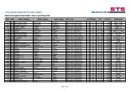
3. <strong>Filter</strong>auslegung<br />
Bei einer <strong>Gas</strong>fließgeschwindigkeit im Eingang von<br />
20 m/s beträgt die <strong>Gas</strong>geschwindigkeit durch das<br />
<strong>Filter</strong>element ca. 0,2 – 0,3 m/s.<br />
Für die Auswahl eines <strong>Filter</strong>s sollte nachstehendes<br />
Diagramm verwendet werden.<br />
Leistungsdiagramm/Performance curve<br />
Typ/Type VZF, VZEF, ZFG, ZEFG<br />
<br />
<br />
<br />
<br />
<br />
<br />
<br />
<br />
<br />
<br />
<br />
<br />
1. General<br />
GTS-cellular filters are designed for filtering gases.<br />
They are mainly used in cabinet systems, in small<br />
gas stations and at the inlet to systems whose<br />
functioning would be impaired by dirt.<br />
2. Special Features<br />
a) Low price<br />
b) Type VZF and ZFG: short fitted length<br />
c) Replaceable filter elements<br />
d) Silumin (Wilmil) casting (VZF/VZEF)<br />
e) Mehanite Nodular (ZFG/ZEFG)<br />
f) Connections for differential pressure<br />
measurement<br />
g) Admitted through DVGW<br />
3. <strong>Filter</strong> Design<br />
With a gas velocity of 20m/s at the filter inlet,<br />
the gas flow through the filter element is approx.<br />
0.2 – 0.3 m/s.<br />
For the correct selection of a filter, following curves<br />
should be used.<br />
<br />
<br />
<br />
<br />
<br />
<br />
<br />
<br />
<br />
<br />
<br />
<br />
<br />
Druckverlust im sauberen Zustand ∆ p (mbar)<br />
Pressure loss across the clean filter element ∆ p (mbar)
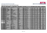
4. Abmessungen/Dimensions<br />
Typ/Type VZF … – 16 und / and ZFG … – 16<br />
Ø Ø Ø ∆<br />
DN H1 H2 L D K b d A p x H3<br />
[mm] [mm] [mm] [mm] [mm] [mm] [mm] ["] ["] [mm] [mm]<br />
1" 126 64 125 55 – – – 1/2 – 35 90<br />
25 126 64 140 115 85 18 14 1/2 1/4 35 90<br />
40 210 90 210 150 110 22 18 1/2 1/4 71 120<br />
50 210 90 210 165 125 22 18 1/2 1/4 71 120<br />
80 376 125 270 200 160 24 18 1 1/4 131 210<br />
100 463 143 320 220 180 25 18 1 1/4 180 235<br />
150 677 173 400 285 240 26 22 1 1/4 295 300<br />
nur Typ VZF/Type VZF only<br />
Typ/Type VZEF … – 16<br />
und/and ZEFG … – 16<br />
5. Gewichte/Weights<br />
Ø Ø Ø ∆<br />
DN H L D K b d p x H3<br />
[mm] [mm] [mm] [mm] [mm] [mm] ["] [mm] [mm]<br />
25 87 78 115 85 18 14 1/4 35 90<br />
50 123 123 165 125 22 18 1/4 70 120<br />
80 259 134 200 160 24 18 1/4 131 210<br />
100 319 159 220 180 24 18 1/4 180 235<br />
DN VZF - 16 VZEF - 16 ZFG - 16 ZEFG - 16<br />
[kg] [kg] [kg] [kg]<br />
1" 1,7 – – –<br />
25 2,0 2,0 6,0 5,5<br />
40 6,7 – – –<br />
50 7,0 7,0 16,0 14,0<br />
80 12,0 10,0 30,0 25,0<br />
100 19,0 14,0 48,0 37,0<br />
150 42,0 – 115,0 –<br />
<br />
<br />
<br />
<br />
<br />
<br />
<br />
<br />
<br />
<br />
<br />
<br />
<br />
Maßänderungen vorbehalten/Dimensions subjects to changes
6. Technische Daten<br />
Anschlüsse<br />
Flanschanschl. PN 16 nach DIN 2501, Teil 1<br />
Gewindeanschl. G1" nach ISO 228, Teil 1<br />
Flanschanschlüsse ANSI 150 auf Anfrage<br />
Betriebsdruck<br />
Mit Gewindeanschluß, 1": 4 bar max.<br />
Mit Flansch, alle Nennweiten: 16 bar max.<br />
Sollen <strong>Filter</strong> der Nennweite 150 als Durchleitungsdruckbehälter<br />
gemäß DVGW G 498<br />
eingesetzt werden, so ist der max. zulässige<br />
Betriebsdruck<br />
mit Werksabnahmezeugnis: 13 bar<br />
mit TÜV-Abnahme (Mehrpreis): 16 bar<br />
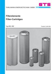
<strong>Filter</strong>element<br />
Das <strong>Filter</strong>element besteht aus sternförmig gefaltetem,<br />
imprägnierten und plissiertem Zellulosepapier.<br />
Innen und außen wird das <strong>Filter</strong>papier<br />
durch stabile, verzinkte Stützkörbe aus<br />
Streckmaterial geschützt.<br />
<strong>Filter</strong>ungsgrad<br />
99,5% der Teilchen > 2µm<br />
Staubspeicherfähigkeit geprüft gemäß DIN<br />
3386, geforderte Staubspeicherfähigkeit<br />
40 mg/cm 2 wurde bei allen Baugrößen erreicht.<br />
Prüfstaub „Air Cleaner Test Dust Fine“<br />
<strong>Filter</strong>fläche<br />
Freie <strong>Filter</strong>fläche = 65 bis 100 x Querschnitt<br />
des <strong>Gas</strong>eingangsstutzens<br />
<strong>Filter</strong>dichtung O-Ring<br />
Dichtwerkstoff nach DIN 3535, Teil 3<br />
<strong>Filter</strong>gehäuse<br />
VZF/VZEF: G Al Si 12<br />
ZFG/ZEFG: GGG 40<br />
Max. Betriebstemperatur 70° C<br />
Differenzdruck<br />
Max. zulässige Druckdifferenz: ∆ p = 0,5 bar<br />
Druckverlust bei <strong>Gas</strong>fließgeschwindigkeit im<br />
Eintritt: v e = 20 m/s: ∆ p ca. 25 mbar<br />
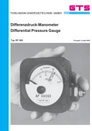
Differenzdruckanschluß<br />
Die <strong>Filter</strong> mit Flanschanschluß sind serienmäßig<br />
mit Differenzdruckanschlüssen G 1/4"<br />
versehen. Gegen Mehrpreis liefern wir ebenfalls<br />
die geeigneten Differenzdruckmanometer,<br />
wahlweise mit oder ohne Schaltkontakte, siehe<br />
hierzu unseren Prospekt 5080<br />
Staubablaßanschluß<br />
Alle <strong>Zellen</strong>gasfilter des Typs VZF und ZFG<br />
(Durchgangsfilter) sind mit Staubablaß versehen.<br />
Eine Ablaßarmatur kann auf Anfrage<br />
geliefert werden.<br />
6. Technical data<br />
Connections<br />
Flange connections PN 16 acc. to<br />
DIN 2501, part 1<br />
Srewed connections G1" acc. to<br />
ISO 228, part 1<br />
Flange connections ANSI 150 on request<br />
Operating Pressure<br />
For screwed connection: 4 bar max.<br />
For flange conn., all sizes: 16 bar max.<br />
If filter of the size DN 150 shall be used as<br />
pressure vessels according to DVGW G 498<br />
the max. permissable pressure is<br />
with works certificate: 13 bar<br />
with TÜV certificate (add. costs): 16 bar<br />
<strong>Filter</strong> Elements<br />
The pleated filtering paper is made of impregnated<br />
cellulose. From either side it is reinforced<br />
by a zinc coated diamond mesh.<br />
Filtration efficiency<br />
99,5 % of the particles > 2µm<br />
Dust-storage-capacity examinated acc. to<br />
DIN 3386, required dust-storage-capacity<br />
40 mg/cm 2 reached for all construction sizes.<br />
Test-dust “Air Cleaner Test Dust Fine”<br />
<strong>Filter</strong>ing surface<br />
Free filtering surface = 65 to 100 times larger<br />
than the diameter of the gas inlet connection<br />
<strong>Gas</strong>ket O-ring<br />
Sealing material acc. to DIN 3535, part 3<br />
<strong>Filter</strong> housing<br />
VZF/VZEF: G Al Si 12<br />
ZFG/ZEFG: GGG 40<br />
Max. Working Temperature 70° C<br />
Differential Pressure<br />
Max. adm. differential pressure: ∆ p = 0,5 bar<br />
pressure loss with gas flow velocity of 20 m/s.<br />
In the inlet connection: V e = 20 m/s: ∆ p<br />
approx. 25 mbar<br />
Differential Pressure Connection<br />
As a standard GTS cellular filters with flange<br />
connections are provided with differential<br />
pressure connections G 1/4". Against extra<br />
cost the filters can be equipped with a differential<br />
pressure gauge provided with or without<br />
switching contacts, see also our leaflet<br />
5080<br />
Dust drain connection<br />
All filters of type VZF and ZFG (straight gas<br />
flow) are provided with a dust drain connection.<br />
A drain valve can be delivered on request.
7. Funktion<br />
Das <strong>Gas</strong> strömt durch den Eingangsstutzen<br />
in das <strong>Filter</strong>gehäuse. Die gegenüber dem<br />
Querschnitt des Eingangsstutzens um 65- bis<br />
100-fach vergrößerte <strong>Filter</strong>fläche reduziert die<br />
Durchströmungsgeschindigkeit auf 1/65<br />
bis1/100. Die dabei im <strong>Gas</strong> mitgeführten<br />
Staubteilchen werden von dem <strong>Filter</strong>element<br />
zurückgehalten. Das gereinigte <strong>Gas</strong> strömt<br />
durch den Ausgangsstutzen ab.<br />
8. Einbauanleitung<br />
Durchflußrichtung unbedingt beachten (siehe<br />
Pfeil), der Gehäusedeckel muß dabei immer<br />
nach oben zeigen.<br />
Der <strong>Zellen</strong>gasfilter soll ohne mechanische<br />
Spannungen in die Rohrleitung eingebaut<br />
werden.<br />
9. Wartungsanleitung<br />
Sicherheitvorschriften der Anlage, in der unser<br />
<strong>Filter</strong> installiert ist, beachten. Armaturen<br />
vor und nach dem <strong>Filter</strong> schließen. <strong>Filter</strong> über<br />
die Anschlußrohrleitung entlüften, d. h. drucklos<br />
machen. Gehäusedeckel demontieren und<br />
das <strong>Filter</strong>element nach oben herausziehen.<br />
Beim Wiedereinsetzen des gereinigten oder<br />
eines neuen <strong>Filter</strong>elementes ist auf einwandfreien<br />
Sitz der O-Ringe zu achten. Das <strong>Filter</strong>element<br />
hat an einem Ende einen Zentrierring,<br />
der den korrekten Sitz des Elementes garantiert.<br />
Beim Einbau befindet sich der Zentrierring<br />
unten im <strong>Filter</strong>.<br />
Deckel schließen, Armaturen vor und nach<br />
dem <strong>Filter</strong> öffnen. <strong>Filter</strong>deckeldichtung auf<br />
Dichtheit prüfen (z. B. mit Lecksucher-Spray).<br />
Zur Gewährung eines reibungslosen Betriebes<br />
empfehlen wir, stets ein <strong>Filter</strong>element in<br />
Reserve zu halten.<br />
10. Qualitätssicherung<br />
Die <strong>Zellen</strong>gasfilter haben eine DVGW-<br />
Registrierung und werden im Rahmen unseres<br />
Qualitätsmanagementsystems DIN EN<br />
ISO 9001 gemäß DVGW Arbeitsblatt G 498<br />
und in Anlehnung an das AD-Merkblatt geprüft.<br />
Die Bau-, Druck-, und Dichtheitsprüfung sowie<br />
die Gehäusewerkstoffe werden mit einem<br />
Werksabnahmezeugnis nach EN 10204/3.1 B<br />
(DIN 50049/3.1 B) bescheinigt.<br />
7. Function<br />
The gas enters through the gas inlet connection.<br />
The filtering surface is 65 to 100 times<br />
larger than the diameter of the gas inlet connection.<br />
Consequently the gas velocity is<br />
reduced to 1/65 to 1/100 of its original<br />
velocity. The dust particles are retained in the<br />
filter element while the clean gas leaves the<br />
filter trough the outlet connection.<br />
8. Installation<br />
When installing the cellular filter always mind<br />
the flow direction (see arrow). The filter cover<br />
must always show upwards. The cellular filter<br />
shall be installed into the pipeline without<br />
applying mechanical strain.<br />
9. Maintenance instructions<br />
Safety rules of the plant, in which our filter will<br />
be fitted, have to be taken into consideration.<br />
Valves in front and after the filter have to be<br />
closed. Ventilate the filter by the supply-pipe<br />
i.e. making it pressureless. Open the filter<br />
cover and take out the filter element, upwards.<br />
When replacing the cleaned filter element or<br />
a new one mind the correct seat of gasket.<br />
Each filter element has an eccentric ring at<br />
one end guaranteeing correct seat of the<br />
element. When inserting the filter element<br />
please mind that the eccentric ring shows<br />
downwards. Close cover, open the valves<br />
upstream and downstream the filter. Examinate<br />
filter-cover-sealing (e.g. with leak-indicator-spray).<br />
In order to ensure continous operation and to<br />
prevent longer interruptions, we advise to<br />
have at least one filter element in stock.<br />
10. Quality Assurance<br />
The cellular gas filters are DVGW-admitted<br />
and tested based on our quality management<br />
system DIN EN ISO 9001 in accordance with<br />
DVGW worksheet G 498 and with reference<br />
to the Technical Rules for Pressure Vessels<br />
(AD-Merkblatt).<br />
The inspection of construction, hydrostatic<br />
pressure and leak test as well as the materials<br />
for the filter casing are certified with a works<br />
certificate in accordance to EN 10204/3.1 B<br />
(DIN 50049/3.1 B).
11. Bestellbeispiel/How to order a cellular gas filter<br />
Bei Bestellung bitte angeben:<br />
1. Typ/type …<br />
2. DN …<br />
3. PN …<br />
4. Mit/ohne Werkabnahmezeugnis nach EN 10204/3.1 B (DIN 50049/3.1 B)<br />
With/without works certificate acc. to EN 10204/3.1 B (DIN 50049/3.1 B)<br />
5. Mit/ohne TÜV-Abnahme<br />
With/Without TÜV certificate<br />
Lieferprogramm<br />
Indirekt Heater<br />
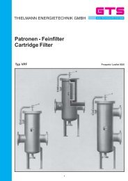
Patronen Feinfilter<br />
<strong>Zellen</strong>-<strong>Gas</strong>filter<br />
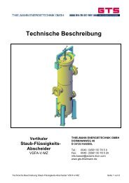
Staub-Flüssigkeitsabscheider, vertikal<br />
Staub-Flüssigkeitsabscheider, horizontal<br />
Flüssigkeitsabscheider<br />
Zyklon-Abscheider<br />
Kondensat-Auffangbehälter<br />
Anfahrsiebe<br />
Erdgas Wärmetauscher, vertikal<br />
Erdgas Wärmetauscher, horizontal<br />
Elektro-Erdgas Wärmetauscher,<br />
explosionsgeschützt<br />
Steuergas-Vorwärmer<br />
Rohrleitungs-Schalldämpfer<br />
Abblase-Schalldämfer<br />
Odoriseure<br />
<strong>THIELMANN</strong> ENERGIETECHNIK GMBH<br />
Product range<br />
indirect heaters<br />
cartridge filters<br />
cellular filters<br />
dust / liquid separators, vertical<br />
dust / liquid seperators, horizontal<br />
liquid-seperators<br />
cyclone separators<br />
condensate-storage-tanks<br />
start-up strainers<br />
natural-gas heat-exchangers, vertical<br />
natural-gas heat-exchangers, horizontal<br />
electrical natural-gas heat-exchangers,<br />
explosion-proof<br />
control-gas preheaters<br />
pipeline silencers<br />
waste-gas silencers<br />
odorizers<br />
Änderungen vorbehalten. Subjekt to change without notice.<br />
10/03<br />
Dormannweg 48<br />
GTS verbessert ihre Produkte ständig und betreibt fortlaufende Weiterentwicklung.<br />
Wir bitten daher um Verständnis, wenn veränderte Ausführungen der Ge-<br />
D-34123 Kassel-Bettenhausen<br />
räte geliefert oder angeboten werden, ohne daß dies vorher angekündigt wird.<br />
Telefon<br />
Telefax<br />
GTS are continously improving their products and constantly carrying on develop-<br />
++49 (0)561 507 85 0<br />
ment. We therefore ask you to appreciate if modified constructions are offered<br />
++49 (0)561 507 85 20 or supplied without giving prior notice.