Patronen-Feinfilter VPF - THIELMANN ENERGIETECHNIK GmbH
Patronen-Feinfilter VPF - THIELMANN ENERGIETECHNIK GmbH
Patronen-Feinfilter VPF - THIELMANN ENERGIETECHNIK GmbH

Sie wollen auch ein ePaper? Erhöhen Sie die Reichweite Ihrer Titel.
YUMPU macht aus Druck-PDFs automatisch weboptimierte ePaper, die Google liebt.
<strong>THIELMANN</strong> <strong>ENERGIETECHNIK</strong> GMBH<br />
<strong>Patronen</strong> - <strong>Feinfilter</strong><br />
Cartridge Filter<br />
Typ <strong>VPF</strong> Prospekt / Leaflet 5025<br />
1<br />
GAS TECHNISCHE SYSTEME
1. Allgemeines<br />
GTS-<strong>Patronen</strong>-<strong>Feinfilter</strong> sind nach dem letzten Stand<br />
der Technik und speziell für die Filterung von Gasen<br />
entwickelt worden. Die Filter entfernen Staub, Rost<br />
und andere feste Schmutzteilchen aus trockenen<br />
Gas- oder Luftströmen.<br />
2. Aufbau und Funktion<br />
GTS-<strong>Patronen</strong>-<strong>Feinfilter</strong> sind in Stahlschweißkonstruktion<br />
ausgeführt. Bei der Konstruktion und Berechnung<br />
werden die Bestimmungen und Richtlinien<br />
für den Bau von Druckbehältern (AD-Merkblätter) zugrunde<br />
gelegt. Ausführungen nach anderen Normen<br />
sind möglich.<br />
Durch den Eingangsstutzen strömt das Gas in das<br />
Filtergehäuse. Größere mitgeführte Verunreinigungen<br />
bzw. Schmutzpartikel werden beim Eintritt des Gases<br />
in den Behälter, bedingt durch die verlangsamte Steiggeschwindigkeit,<br />
bereits ausgeschieden und sammeln<br />
sich im unteren Filterteil an. Danach durchdringt das<br />
Gas den Filtereinsatz von außen nach innen. Verunreinigungen<br />
werden zurückgehalten. Das gereinigte Gas<br />
strömt durch den Ausgangsstutzen weiter.<br />
Bild/Fig. 1<br />
2<br />
1. General<br />
GTS cartridge filters have been particularly developed<br />
as a successful approach to the challenging demand<br />
of advanced filtering technology for gases, removing<br />
dust, rust and other solid contaminants from dry gas<br />
and air stream.<br />
2. Construction and Operation<br />
GTS cartridge filters are fabricated from high quality<br />
steel, making special allowance in design and<br />
construction for the requirements of international<br />
codes and standards covering pressure vessels.<br />
Constructions to other standards are available on<br />
customer’s request and specification.<br />
The gas flows through the inlet connection into the<br />
filter chamber, known as the quiet zone, where the<br />
larger particles are retained, due to a decrease in gas<br />
velocity. Particles removed from the gas stream this<br />
way will be collected in the bottom section of the filter<br />
housing. The gas then flows through the filter cartridge<br />
from outside where any remaining contamination in the<br />
gas is retained. The clean gas now leaves the filter<br />
chamber through the outlet connection.<br />
Bild/Fig. 2 Filterelement Zellulose<br />
Cartridge Cellulose
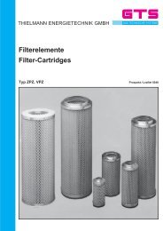
3. Filterelemente<br />
3.1 Filtermedium (Zellulose)<br />
Das Filterpapier ist sternförmig plissiertes Zellulosepapier,<br />
das eine Filterfeinheit von 2 µ bei einem Abscheidegrad<br />
um 99,5 % gewährleistet. Das Filterpapier<br />
ist mit Polyesterfasern verstärkt und mit Phenolharz<br />
imprägniert. Das Filterpapier ist deshalb feuchtigkeitsabweisend.<br />
3.2 Aufbau<br />
Innen und außen wird das Filterpapier durch stabile<br />
Stützkörbe aus 1 mm starkem verzinktem Streckmetall<br />
geschützt. Streckmetall bietet eine größere freie<br />
Gasdurchtrittsfläche als z. B. Lochbleche.<br />
Die beiden Enden der Patrone sind mit einem erdgasbeständigen<br />
Zweikomponentenkleber dauerhaft und<br />
fest verbunden. Beide <strong>Patronen</strong>flächen sind mit einem<br />
Dichtungsring aus 5 mm dickem Filz versehen. Durch<br />
den Dichtungsring werden fertigungsbedingte Maßtoleranzen<br />
– in gewissen Grenzen – ausgeglichen und<br />
ein sicherer Dichtabschluss gewährleistet.<br />
3.3 Korrosionsschutz<br />
Alle Stahlteile sind verzinkt.<br />
Bild/Fig. 3 Vergrößerung: Zellstoff 100 x<br />
Enlargement: cellulose 100 x<br />
Bild/Fig. 4 Vergrößerung Zellstoff 500 x<br />
Enlargement: cellulose 500 x<br />
3<br />
3. Filter Cartridges<br />
3.1 Filter Medium (Cellulose)<br />
The filter paper is constructed with layers of cellulose<br />
fibres, reinforced with polyester fibre and impregnated<br />
with phenolic resin to make it resistant to moisture.<br />
This construction ensures a nominal grade of filtration<br />
of 2 µ with an efficiency of 99.5 %. The cellulose paper<br />
medium is then pleated and radially arranged to form<br />
a star pattern to give a high filter area for dirt retention.<br />
3.2 Construction of the Cartridge<br />
The filter paper is supported inside and outside by<br />
sturdy basket shaped metal mesh of 1 mm thickness,<br />
the metal mesh giving a bigger surface area, being<br />
more permeable to gas than any other material, e. g.<br />
perforated plates.<br />
The two cartridge ends are permanently and securely<br />
fixed by two components of mixed adhesive being<br />
resistant to the natural gas. The two cartridge end<br />
faces are sealed by a felt gasket of 5 mm thickness<br />
which, to a certain extent, compensates for variations<br />
in dimension imposed by work tolerances, and<br />
ensures tight seal.<br />
3.3 Protection against Corrosion<br />
All steel components are galvanized.<br />
Bild/Fig. 5 Maschenseite (15fache Vergrößerung)<br />
Mesh side (15 x enlargement)<br />
and the non uniform top side<br />
Bild/Fig. 6 Lagenseite (15fache Vergrößerung)<br />
Layer side (15 x enlargement)
3.4 Druckverlust<br />
Als Druckverlust über die Patrone gemessen, sind<br />
maximal 800 mbar zulässig. Bei einem Druckverlust<br />
um etwa 400 – 500 mbar sollten die <strong>Patronen</strong> gewechselt<br />
werden. Die Pressluft-Reinigung einer<br />
trockenverschmutzten Patrone ist immer ein Notbehelf.<br />
Auch wenn die Filteroberfläche danach „sauber”<br />
scheint, sitzen die Schmutz- und Staubpartikel tief in<br />
der Zellulose. Ein so anscheinend sauberer Filter hat<br />
höchstens noch eine Standzeit von 50 % im Vergleich<br />
zu einer neuen Patrone.<br />
4. Abmessungen 4. Dimensions<br />
Ausführung/Type: 1<br />
GAS TECHNISCHE SYSTEME<br />
DN 1<br />
H* Ausbauhöhe<br />
Ausführung/Type: 2<br />
DN 2<br />
G½“<br />
DN 2<br />
D<br />
D<br />
G½“<br />
G½“<br />
B<br />
B<br />
G½“<br />
DN 1<br />
G½“<br />
G½“<br />
ca. 200<br />
h 2<br />
H* Ausbauhöhe<br />
ca. 200<br />
DN 1<br />
h 2<br />
DN 1<br />
h 3<br />
h 1<br />
h 3<br />
h1<br />
H*<br />
h 4<br />
H*<br />
h 4<br />
Ausführung / Construction 1<br />
Grund-<br />
Typ<br />
Basic Type<br />
Filter<br />
Filter-<br />
Patr.<br />
Anz.<br />
<strong>Patronen</strong><br />
no.<br />
of<br />
filter<br />
Filter<br />
cartr.<br />
cartridges Ausführung / Construction 2<br />
4<br />
D<br />
[ mm]<br />
3.4 Pressure Drop<br />
The pressure drop, allowed for the cartridges, is max.<br />
800 mbar. The cartridges shall be replaced as soon as<br />
the pressure drop of 400 to 500 mbar is reached. Purging<br />
of a dry contaminated cartridge by a jet of<br />
compressed air to make it re-usable is nothing more<br />
than an expedient to overcome the shortcoming of<br />
an emergency. Even though the filter surface appears<br />
to be clean after this purging operation, one may rest<br />
assured that dust particles are jammed tight in the<br />
depths of the filter pours. The service life of a filter<br />
being apparently recovered for operation this way is no<br />
more than 50 % as compared to a new cartridge.<br />
B<br />
[ mm]<br />
h h h h H * D N 1 D N 2<br />
1 2 3 4<br />
[ mm]<br />
[ mm]<br />
[ mm]<br />
[ mm]<br />
[ mm]<br />
[ mm]<br />
[ mm]<br />
Menge<br />
Rate omf<br />
flow<br />
3 [ / h]<br />
<strong>VPF</strong>1. 150<br />
1 60/ 200<br />
168. 3 4 50<br />
– 3003 20<br />
– 300 5 0 G1" 200<br />
<strong>VPF</strong>1. 200<br />
1 90/ 400<br />
219. 1 5 50<br />
– 3505 30<br />
– 500 8 0 G1" 400<br />
<strong>VPF</strong>1. 250<br />
1 120/ 600<br />
273. 0 6 50<br />
– 3507 50<br />
– 700 1 00<br />
G1" 800<br />
<strong>VPF</strong>1. 300<br />
1 170/ 800<br />
323. 9 700700 500980 1680900 15050 1.<br />
600<br />
<strong>VPF</strong>2. 400<br />
2 220/ 500<br />
406. 4 820700 5001200 1900600 20080 2.<br />
500<br />
<strong>VPF</strong>2. 500<br />
2 270/ 600<br />
508. 0 960800 6001440 2240700 250100 4.<br />
000<br />
<strong>VPF</strong>2. 600<br />
2 350/ 600<br />
600. 0 1100900 7001500 2400700 300100 5.<br />
000<br />
<strong>VPF</strong>4. 700<br />
4 170/ 800<br />
700. 0 1200900 7001100 2000900 300100 6.<br />
500<br />
<strong>VPF</strong>6. 800<br />
6 220/ 500<br />
800. 0 13001000 8001400 2400600 400150 9.<br />
000<br />
<strong>VPF</strong>6. 900<br />
6 270/ 600<br />
900. 0 15001000 8001850 2850700 500150 12.<br />
000<br />
<strong>VPF</strong>10. 1000<br />
10 220/ 500<br />
1050. 0 16001200 9501600 2800600 500150 14.<br />
000<br />
Grund-<br />
Typ<br />
Basic<br />
Type<br />
Filter<br />
Filter-<br />
P a<br />
.<br />
tr<br />
Anz.<br />
<strong>Patronen</strong><br />
no.<br />
of<br />
filter<br />
cartr.<br />
Filter<br />
cartri<br />
dges<br />
D<br />
[ mm]<br />
B h h h h H*<br />
DN<br />
1 DN<br />
2<br />
1 2 3 4<br />
[ mm]<br />
[ mm]<br />
[ mm]<br />
[ mm]<br />
[ mm]<br />
[ mm]<br />
[ mm]<br />
[ mm]<br />
Menge<br />
Rate<br />
of<br />
flow<br />
3 [ m / h]<br />
<strong>VPF</strong>1. 150<br />
1 60/ 200<br />
168. 3 2 25<br />
– 3003 40<br />
– 300 5 0 G1" 200<br />
<strong>VPF</strong>1. 200<br />
1 90/ 400<br />
219. 1 2 75<br />
– 3505 80<br />
– 500 8 0 G1" 400<br />
<strong>VPF</strong>1. 250<br />
1 120/ 600<br />
273. 0 3 25<br />
– 3508 20<br />
– 700 1 00<br />
G1" 800<br />
<strong>VPF</strong>1. 300<br />
1 170/ 800<br />
323. 9 350700 5001080 1980900 15050 1.<br />
600<br />
<strong>VPF</strong>2. 400<br />
2 220/ 500<br />
406. 4 410700 5001320 2280600 20080 2.<br />
500<br />
<strong>VPF</strong>2. 500<br />
2 270/ 600<br />
508. 0 480800 6001580 2680700 250100 4.<br />
000<br />
<strong>VPF</strong>2. 600<br />
2 350/ 600<br />
600. 0 550900 7001640 2870700 300100 5.<br />
000<br />
<strong>VPF</strong>3. 700<br />
3 170/ 800<br />
700. 0 580800 6501220 2350900 300100 5.<br />
500<br />
<strong>VPF</strong>6. 800<br />
6 220/ 500<br />
800. 0 6501000 8001510 2880600 400150 9.<br />
000<br />
<strong>VPF</strong>7. 900<br />
7 170/ 800<br />
900. 0 7501200 9501420 3100900 500150 12.<br />
000
5. Temperatur<br />
Für die Festigkeitsberechnung der Filtergehäuse wird<br />
der Temperaturbereich von -10 °C bis +50 °C zugrunde<br />
gelegt. Andere Auslegungstemperaturen sind möglich,<br />
erfordern aber eine neue Festigkeitsberechnung.<br />
Das Filtermedium ist für einen Temperaturbereich von<br />
-50 °C bis +70 °C ausgelegt.<br />
Auf Anfrage sind jedoch auch Filterelemente für eine<br />
Dauerbetriebstemperatur bis 230 °C verfügbar.<br />
6. Anschlüsse<br />
6.1 Differenzdruck- und Entlüftungsanschluss<br />
Die Filter sind mit zwei Differenzdruck- und einem<br />
Entlüftungsanschluss G ” versehen. Bei Durchflussrichtung<br />
von links nach rechts sind sie vorn angeordnet.<br />
6.2 Staub-Ablass-Anschluss<br />
Sämtliche GTS-<strong>Patronen</strong>-<strong>Feinfilter</strong> sind mit einem<br />
Staubablassanschluss (Muffe bzw. Stutzen) versehen.<br />
Im Normalfall ist dieser mit einem Stopfen G 1” bzw.<br />
einem Blindflansch verschlossen. Sonderausführungen<br />
sind gegen Aufpreis möglich. Gegen Mehrpreis<br />
kann eine Ablassarmatur mitgeliefert werden.<br />
7. Einbau<br />
Unbedingt Durchflussrichtung beachten.<br />
Der <strong>Patronen</strong>-<strong>Feinfilter</strong> soll ohne mechanische Spannung<br />
in die Rohrleitung eingebaut werden.<br />
8. Filter-<strong>Patronen</strong>-Austausch<br />
Sicherheitsvorschriften und Richtlinien beachten.<br />
Armaturen vor und nach dem Filter schließen.<br />
Unbedingt entlüften, d. h. drucklos machen. Ist<br />
kein weiterer Entlüftungsstutzen vorhanden, kann der<br />
Differenzdruckanschluss verwandt werden.<br />
Filterdeckel bzw. Schnellverschlussplatte abnehmen<br />
bzw. zur Seite schwenken.<br />
Filterpatronen nach Lösen der Befestigung herausnehmen.<br />
Filterpatronen austauschen.<br />
Zur Gewährleistung eines reibungslosen Betriebes<br />
empfiehlt es sich, einen kompletten Reserve-<strong>Patronen</strong>einsatz<br />
auf Lager zu halten.<br />
Beim Wiedereinsetzen unbedingt Auflagefläche bzw.<br />
Dichtkante von allen Verschmutzungen reinigen. Ebenso<br />
die Auflagefläche der <strong>Patronen</strong>verschlussplatte.<br />
Achtung: Die nachgeschalteten Geräte sind nur dann<br />
wirksam gegen Schmutz geschützt, wenn diese Arbeiten<br />
mit größter Sorgfalt durchgeführt werden.<br />
5<br />
5. Temperature<br />
The stress calculation of the filter housing is based on<br />
a temperature of +50 °C. It is possible to expose the<br />
filter for operation to higher temperatures, in which<br />
case, however, the stress calculation shall be revised.<br />
The filtering medium is designed for a temperature<br />
range between -50 °C and +70 °C.<br />
On request fiter elements for continuous operating<br />
temperatures up to 230 °C are available.<br />
6. Connections<br />
6.1 Differential Pressure<br />
Tapping and Vent Connections<br />
The filter housings are equipped with two differential<br />
pressure tapping connections and one vent<br />
connection, size DN G ”. In units with the direction of<br />
flow passing from left to right, such connections are<br />
arranged at the front of the filter housing.<br />
6.2 Dust-Condensate Removal Connection<br />
GTS cartridge filters are equipped with a dust removal<br />
connection (socket or stud) being normally blanked off<br />
by plug G1” or a blind flange. Special constructions are<br />
available on request.<br />
As an optional extra, a evacuation valve can be made<br />
available at extra cost.<br />
7. Installation<br />
It is most important to take into account the direction<br />
of flow when installing the unit.<br />
The cartridge filter shall be installed into the pipeline<br />
without applying mechanical strain.<br />
8. Replacement of Filter Cartridges<br />
Observe rules and regulations of the safety code.<br />
Close valves up stream and down stream of filter. It is<br />
most important to depressurize the unit. Where<br />
there are no extra vent connections available, use differential<br />
pressure tappings for this purpose. Remove<br />
filter cover or swivel aside quick closing plate.<br />
Disengage cartridge retainer and withdraw the<br />
cartridge. Replace filter cartridges.<br />
To minimise interruptions of operation, it is recommended<br />
to hold a set of spare cartridges in store.<br />
When replacing cartridges, make sure a clean sealing<br />
edge and support area of cartridge closing plate, so<br />
that all impurities are removed.<br />
Attention: Safe protection against contamination is<br />
given to instruments installed down stream of the filter<br />
only, where utmost care is observed in performing<br />
these works.
9. Verschließen des Filters<br />
9.1 Mit Flansch-Deckel-Verschluss<br />
Dichtung und Dichtflächen reinigen; Verschlussdeckel<br />
auflegen; Schrauben diametral einsetzen und zuerst<br />
leicht anziehen; erst danach festziehen; unbedingt<br />
Verkanten des Deckels vermeiden.<br />
9.2 Mit GTS-Schnellverschluss<br />
Die geschliffene Innenseite mit einem sauberen Tuch<br />
reinigen und mit einem Silikonfett leicht einfetten.<br />
O-Ringe aus der Deckelnut herausnehmen und mit<br />
einem weichen, sauberen Tuch reinigen. Danach mit<br />
Silikonfett leicht einfetten.<br />
Die O-Ring-Nut im Schnellverschlussdeckel ebenfalls<br />
mit einem weichen, sauberen Tuch reinigen und einfetten.<br />
O-Ring wieder in die Deckelnut einlegen.<br />
Keine Werkzeuge dazu verwenden.<br />
Geringste mechanische Beschädigungen, wie Kratzer,<br />
Einstiche etc. stellen die Dichtheit des Verschlusses<br />
in Frage.<br />
Den Deckel langsam in Schnellverschlussrichtung<br />
(am Filteroberteil) einbringen, die Teile einlegen und<br />
sichern.<br />
Bei Wiederinbetriebnahme ist ein relativ rasches Öffnen<br />
der Eingangsarmatur, d. h. ein Druckstoß ggf. erforderlich,<br />
um den O-Ring in die richtige Position zu<br />
bringen und damit die Dichtheit des Schnellverschlusses<br />
herzustellen. Ist der <strong>Patronen</strong>filter im<br />
Freien aufgestellt, so ist eine Schutzhaube erforderlich,<br />
um ein Eindringen von Wasser und Schmutz in<br />
den Schnellverschluss zu verhindern.<br />
Bild/Fig. 7<br />
Filterelement<br />
Cartridge<br />
Beispiele für Stutzenstellung<br />
Example for position of connection<br />
Bild/Fig. 8<br />
Eingang 180° Eingang 270°<br />
Ausgang 0° Ausgang 0°<br />
inlet 180° inlet 270°<br />
outlet 0° outlet 0°<br />
6<br />
9. Closing of the Filter<br />
9.1 With bolted cover plate<br />
Clean gasket and faces; lay cover on support area;<br />
insert bolts by way of diametrical sequence, screw on<br />
finger tight only, thereafter tighten up screw<br />
diametrical sequence to avoid tilting of cover.<br />
9.2 With GTS quick closing device<br />
First clean internal face, being ground to flat finish, use<br />
clean cloth, then slightly lubricate with silicone grease.<br />
Withdraw O-rings from cover slot. Clean with soft cloth<br />
and slightly lubricate with silicone grease.<br />
Clean O-ring slot of quick closing cover, too, using soft<br />
clean cloth, then lubricate.<br />
Place O-ring back into O-ring slot of cover.<br />
Desist from using tools.<br />
Even slightest mechanical deteriorations such as<br />
scratches, punctures, etc. are susceptible to affect<br />
tight seal of cover.<br />
Slowly move cover in sense of quick closing device<br />
(on top of filter), replace and secure parts.<br />
While re-starting the unit for operation, a comparably<br />
quick opening operation of the inlet valve, i. e. possibly<br />
a pressure surge, is required to put the O-ring into its<br />
proper position and thus to ensure safe seal of the<br />
quick closing device. Where the cartridge filter is<br />
installed outdoors so as to be exposed to the open air<br />
while operating, a protecting cap shall be provided to<br />
prevent water and dirt from penetrating into the quick<br />
closing device.<br />
Schnellverschluss<br />
Quik Closing Device<br />
Bild / Fig. 9<br />
(siehe separaten<br />
Prospekt 5070)<br />
(please refer to separate<br />
leaflet 5070)
10. Qualitätssicherung<br />
Konstruktion und Fertigung der <strong>Patronen</strong>filter werden<br />
im Rahmen unseres Qualitätsmanagementsystems<br />
DIN EN ISO 9001 gemäß AD-Merkblatt und DVGW<br />
Arbeitsblatt G 498 (oder anderer Druckbehälter Standards)<br />
geprüft.<br />
Die Abnahme der Druckbehälter erfolgt grundsätzlich<br />
durch Sachverständige des TÜV oder anderer dritter<br />
Sachverständiger (Lloyd`s Register, Germanischer<br />
Lloyd, Bureau Veritas etc.).<br />
Prüf- und Materialzeugnisse werden von den Sachverständigen<br />
erstellt und sind integraler Bestandteil des<br />
Produktes.<br />
11. Bestellangaben<br />
Bei Bestellung eines <strong>Patronen</strong>filters bitten wir um folgende<br />
Angaben:<br />
1. Ausführung 1 oder 2<br />
Anschlussflansche (DN, PN, DIN, ANSI)<br />
2. Durchflussmenge Vn [m /h]<br />
(Normkubikmeter)<br />
3. Vordruckbereich p e min und p e max [bar]<br />
4. Berechnungsdruck (Konzessionsdaten<br />
und -temperatur)<br />
5. Betriebstemperaturen [°C]<br />
6. Medium (gegebenenfalls Gasanalyse)<br />
7. Deckelschwenkvorrichtung<br />
(bei Schnellverschluss mit Abziehvorrichtung)<br />
8. Schnellverschluss<br />
9. Stutzenausführung und Kondensatablass<br />
10. Sonderwünsche (gegen Mehrpreis)<br />
Abnahme: TÜV / TÜH, DVGW, Lloyds, etc.<br />
11. Zusatzeinrichtung für Filterdifferenzdruckmessung:<br />
Differenzdruckmessgeräte (Anzeige, Anzeige<br />
mit Schleppzeiger, elektr. Kontaktgabe)<br />
12. Typenschildstellung (Normalausführung) sichtbar<br />
bei Gasdurchfluss von links nach rechts; bzw. bei<br />
zwei Filtern in einer Anlage: 1 x normal und 1 x<br />
spiegelbildlich<br />
13. Kunststoff-Schutzhaube für Schnellverschluss<br />
14. Andere Nennweiten der Anschlussstutzen als in<br />
der Tabelle angegeben<br />
15. Ausführung für besonders starken Staubanfall.<br />
Steigegeschwindigkeit im Behälter ca. 2 m/sec.<br />
16. Andere Anschlussarten zu Stutzenanordnungen<br />
(z. B. Eckfilter)<br />
7<br />
10. Quality assurance<br />
Design and Manufacturing of the cartridge filters are<br />
checked and tested based on our quality management<br />
system DIN EN ISO 9001 and in accordance to AD-<br />
Merkblatt and DVGW worksheet G 498 (or other<br />
pressure vessel codes).<br />
The acceptance of the pressure vessels is carried out<br />
by experts of TÜV or other third party experts (Lloyd`s<br />
Register, Germanischer Lloyd, Bureau Veritas etc.).<br />
Test- and materialcertificates are providet by the<br />
experts and they are integral part of the product.<br />
11. Data to be Stated with Order<br />
With order and special constructions, please state<br />
when ordering a cartridge filter:<br />
1. Version 1 or 2<br />
Flanges (DN, PN, DIN, ANSI)<br />
2. Rate of flow Vn [m /h] (standard cubic metres)<br />
3. Upstream pressure range p e min und p e max [bar]<br />
4. Design pressure and temperature<br />
5. Operating temperatures [°C]<br />
6. Medium to be treated (possibly gas analysis)<br />
7. Cover swivelling device (in case of quick closing<br />
device with extractor)<br />
8. Quick closing device<br />
9. Type of connections for condensate drain<br />
10. Special options (against extra charge)<br />
Acceptance: , TÜV / TÜH, DVGW, Lloyds, etc.<br />
11. Special instrumentation for filter, differential<br />
pressure gauge, differential pressure gauge<br />
indicator with drag pointer, electric contact<br />
transmission<br />
12. Name plate (standard design) – Oriantation (to be<br />
visible with direction of gas flow from left to right)<br />
or with two filter units in one skid: 1 x normal and<br />
1 x mirror-inverted<br />
13. Plastic protective cap for quick closing device<br />
14. Connection sizes differing from those indicated in<br />
table<br />
15. Construction for particular occurence of dust, gas<br />
velocity in chamber appr. 2 m/s<br />
16. Other types of connections (e. g. angle filters)
12. Typenbezeichnung<br />
Beispiel<br />
Lieferprogramm<br />
Indirekt Heater<br />
<strong>Patronen</strong>-<strong>Feinfilter</strong><br />
Siebkorbfilter<br />
Zellen-Gasfilter<br />
Staub-Flüssigkeitsabscheider, vertikal<br />
Staub-Flüssigkeitsabscheider, horizontal<br />
Zyklon-Abscheider<br />
Anfahrsiebe<br />
Erdgas-Wärmetauscher, vertikal<br />
Erdgas-Wärmetauscher, horizontal<br />
Elektro-Erdgas-Wärmetauscher, explosionsgeschützt<br />
Steuergas-Vorwärmer<br />
Rohrleitungs-Schalldämpfer<br />
Abblase-Schalldämpfer<br />
Odoriseure<br />
Kühler<br />
Druckbehälter<br />
<strong>VPF</strong> 1. 250. 16.100. 1<br />
<strong>THIELMANN</strong> <strong>ENERGIETECHNIK</strong> GMBH<br />
Dormannweg 48<br />
D-34123 Kassel-Bettenhausen<br />
Telefon ++49 (0)561 507 85 0<br />
Telefax ++49 (0)561 507 85 20<br />
8<br />
12. Designation of type<br />
Example<br />
Ausführung / type<br />
DN Stutzen / DN connection size<br />
PN<br />
Behälter-Außendurchmesser / Vessel outside diameter<br />
Anzahl der Filterelemente / No. of filter cartridges<br />
<strong>Patronen</strong>-<strong>Feinfilter</strong> / Cartridge filter<br />
Product range<br />
indirect heater<br />
cartridge filter<br />
wire-basket strainer<br />
cellular filter<br />
dust/liquid separator, vertical<br />
dust/liquid separator, horizontal<br />
cyclone separator<br />
start up strainer<br />
natural-gas heat-exchanger, vertical<br />
natural-gas heat-exchanger, horizontal<br />
electr. natural-gas heat-exchanger, explosion-proofed<br />
control-gas preheater<br />
pipeline silencer<br />
waste-gas silencer<br />
odorizers<br />
coolers<br />
pressure vessels<br />
Änderungen vorbehalten. Subject to change without notice.<br />
GTS verbessert ihre Produkte ständig und betreibt fortlaufende Weiterentwicklung.<br />
Wir bitten daher um Verständnis, wenn veränderte Ausführungen<br />
der Geräte geliefert oder angeboten werden, ohne daß dies vorher angekündigt<br />
wird.<br />
GTS are continuously improving their products and constantly carry on<br />
development. We therefore ask you to appreciate if modified constructions<br />
are offered or supplied without giving prior notice.<br />
3/99