ESX Signum SC1000 Powercap - Audio Design GmbH
ESX Signum SC1000 Powercap - Audio Design GmbH
ESX Signum SC1000 Powercap - Audio Design GmbH

Sie wollen auch ein ePaper? Erhöhen Sie die Reichweite Ihrer Titel.
YUMPU macht aus Druck-PDFs automatisch weboptimierte ePaper, die Google liebt.
Rev. Vers. 1.1
BEDIENUNGSANLEITUNG<br />
Inhaltsverzeichnis Seite<br />
Verwendungsmöglichkeiten 3<br />
Sicherheitshinweise 4<br />
Montage 5<br />
Erstes Aufladen 5<br />
Anschlussbeispiele 6<br />
Funktionsbeschreibung 7<br />
Entladen 8<br />
Justierung der Voltanzeige 8<br />
TECHNISCHE DATEN<br />
Nenn-Kapazität: 1.0 Farad<br />
Dauer-Betriebsspannung: 12 ~ 16V DC<br />
Maximale Betriebsspannung: 20V DC max.<br />
Betriebstemperatur: –20 ~ + 60° C<br />
Abmessungen (ohne Montagehalter): ø76 x 285 mm<br />
LIEFERUMFANG<br />
1 Pufferkondensator<br />
2 Montagehalter<br />
1 Lade-/Entlade-Widerstand<br />
1 Bedienungsanleitung<br />
Einbauzubehör<br />
Technische Änderungen vorbehalten!<br />
2
VERWENDUNGSMÖGLICHKEITEN<br />
Der Pufferkondensator wird in Kraftfahrzeugen zur Stabilisierung und<br />
Unterstützung der Stromversorgung eines Verstärkers eingesetzt, wenn dieser<br />
schnell und für kurze Zeit hohe Ströme benötigt. Er kann kurzfristige Belastungen<br />
der Bordspannungen bei z.B. besonders tiefen, kräftigen Bässen ausgleichen.<br />
Durch die Verwendung des Pufferkondensators ergibt sich eine wesentlich<br />
bessere Leistungsentfaltung des Verstärkers.<br />
Car <strong>Audio</strong> Verstärker benötigen für den optimalen Betrieb hohe Stromstärken.<br />
Herkömmliche Fahrzeugbatterien sind normalerweise nicht für die zusätzliche<br />
Versorgung eines Verstärkers ausgelegt.<br />
Ein weiterer Vorteil des Pufferkondensators ist das Filtern von Wechselspannungen,<br />
die im Netzteil des Verstärkers indiziert werden. Ungefilterte<br />
Wechselspannungen können hörbare Interferenzen verursachen.<br />
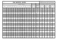
Bassleistung bei 50Hz und 70Hz<br />
ohne Pufferkondensator<br />
3<br />
Bassleistung bei 50Hz und 70Hz<br />
mit Pufferkondensator
SICHERHEITSHINWEISE<br />
Bevor Sie mit der Installation des Kondensators beginnen, sollten Sie die<br />
folgenden Anweisungen der Bedienungsanleitung genau befolgen!<br />
Andernfalls besteht Verletzungsgefahr oder das Gerät könnte ernsthaft<br />
beschädigt werden.<br />
Der Pufferkondensator entspricht der KFZ-Richtlinie für den Betrieb in Fahrzeugen<br />
innerhalb der Europäischen Union und besitzt eine E-Zertifizierung als auch<br />
eine CE-Kennzeichnung (Konformitätserklärung).<br />
Der Anschluss des Pufferkondensators an das 12 V-Bordnetz darf nur durch<br />
qualifiziertes Fachpersonal erfolgen. Dabei ist besondere Sorgfalt geboten. Bei<br />
Kurzschlüssen können gefährlich hohe Ströme fließen.<br />
Der Pufferkondensator speichert sehr hohe Stromreserven und könnte bei<br />
falscher Handhabung sogar explodieren. Wird der Kondensator zweckentfremdet,<br />
nicht richtig angeschlossen oder nicht fachgerecht repariert, können Sach- oder<br />
Personenschäden daraus resultieren.<br />
Der Kondensator muss fest und fachgerecht an einer mechanisch stabilen Stelle<br />
montiert werden.<br />
Auf keinen Fall darf der Pufferkondensator mit einer höheren Spannung als 20<br />
Volt betrieben werden oder ein Kurzschluss an den Strom-Anschlussklemmen<br />
verursacht werden.<br />
Schützen Sie den Kondensator vor Feuchtigkeit und Hitze (zulässiger<br />
Einsatztemperaturbereich -20 °C bis +60 °C).<br />
Für die Reinigung nur ein weiches, trockenes Tuch verwenden, auf keinen Fall<br />
Chemikalien oder Wasser.<br />
VORSICHT<br />
ELEKTROSCHOCK<br />
4
MONTAGE<br />
Für bestmögliche Ergebnisse sollte der Kondensator so nahe wie möglich bei<br />
der Endstufe installiert werden. Die Kabel zwischen dem Kondensator und der<br />
Endstufe sollten möglichst kurz sein und einen möglichst großen Querschnitt<br />
aufweisen. Die Kabel sind so zu verlegen, dass deren Isolierung während des<br />
Einbaus und des Betriebes nicht beschädigt werden.<br />
1.) Verwenden Sie die beiliegenden Halter um den Kondensator an einer<br />
mechanisch stabilen Stelle fest anzuschrauben. Montieren Sie das Gerät<br />
keinesfalls auf stark vibrierenden Flächen wie beispielsweise einem Gehäusesubwoofer.<br />
2.) Der korrekte Anschluss ist auf der nächsten Seite dargestellt. Zur Vermeidung<br />
von Störgeräuschen sollte der Masseanschluss des Kondensator an der gleichen<br />
Stelle erfolgen, an der auch der Verstärker angeschlossen wird.<br />
ERSTES AUFLADEN<br />
Beim erstmaligen Aufladen des Kondensators sollte unbedingt der beiliegende<br />
Lade-/Entlade-Widerstand benutzt werden um den Ladestrom zu begrenzen<br />
und Anschlussfunken zu vermeiden. Verbinden Sie dabei das Massekabel „-”<br />
mit dem „-” Anschluss des Kondensators. Dann klemmen Sie den beigelegten<br />
Widerstand an den „+“ Anschluss des Kondensators und halten das „+“ Kabel<br />
des Batterieanschlusses bzw. des Verteilerblocks an das andere Ende des<br />
Widerstands.<br />
Der Widerstand kann nach ca. drei Minuten oder wenn der Kondensator ca. 10<br />
Volt erreicht hat entfernt werden. Schließen Sie nun das „+“ Kabel der Batterie<br />
an den „+“ Anschluss des Kondensators an, um den Ladevorgang bis zu 12~14V<br />
abzuschließen.<br />
ACHTUNG:<br />
Der Widerstand könnte während des Ladens sehr heiß werden.<br />
Achten Sie unbedingt darauf, die Terminals nicht kurzzuschließen!<br />
”–” Masseanschluss<br />
Widerstand<br />
5<br />
”+” Batterieanschluss
ANSCHLUSSBEISPIELE<br />
Anschluss mit Verteilerblock (empfohlen)<br />
Batt.<br />
Sicherung<br />
Remote-Steuerleitung<br />
vom Autoradio/Steuergerät<br />
Anschluss ohne Verteilerblock<br />
Batt.<br />
Verteilerblock<br />
Sicherung<br />
Remote-Steuerleitung<br />
vom Autoradio/Steuergerät<br />
Hinweis:<br />
Achten Sie auf korrekte Polung!<br />
6<br />
Verstärker<br />
Hinweis:<br />
Achten Sie auf korrekte Polung!<br />
Verstärker
FUNKTIONSBESCHREIBUNG<br />
Digital Voltanzeige<br />
Diese Anzeige zeigt die aktuelle Betriebsspannung in Volt an und ist somit eines<br />
der wichtigsten Features zur Statusanzeige der Stromversorgung des Fahrzeuges.<br />
Die Spannungsanzeige schaltet sich erst ein, sobald 12V am Remote-Anschluss<br />
anliegen und eine Spannung von ca. 5 ~ 10 Volt an den Anschlüssen anliegt.<br />
Kontroll-LED<br />
Bei großen Spannungsschwankungen oder bei Spannungsabfall beginnt die<br />
Kontroll-LED blau zu blinken. Überprüfen Sie dann die Bordspannung des<br />
Fahrzeugs oder die Strom-Anschlüsse auf fehlerhafte Befestigung.<br />
Potentiometer<br />
Dieser Regler erlaubt die Justierung der Voltanzeige. Mehr Informationen dazu<br />
auf Seite 8.<br />
Autoremote<br />
Der Kondensator ist mit einer automatischen Aus- und Einschaltfunktion<br />
ausgestattet. Solbald der Kondensator eine Spannungsschwankung bemerkt,<br />
schaltet er sich von selbst ein und schaltet sich wieder von selbst aus, wenn<br />
ca. zwei Minuten keine Schwankung bzw. Aktivität bemerkt wurde.<br />
WARNUNG Explosionsgefahr:<br />
Achten Sie immer auf die korrekte Polung der Anschlüsse (”Batterie +” auf<br />
“Anschluss +” und “Masse –” auf “Anschluss – “). Vertauschen Sie diese<br />
niemals, andernfalls besteht akute Explosionsgefahr.<br />
”–” Masseanschluss<br />
Kontroll-LED<br />
Digitale Voltanzeige<br />
7<br />
Potentiometer<br />
”+” Batterieanschluss
ENTLADEN<br />
Wenn der Kondensator ausgebaut werden sollte, muss dieser aus Sicherheitsgründen<br />
komplett entladen werden. Zum Entladen des Kondensators<br />
entfernen Sie das Kabel am „+“ Anschluss des Kondensator. Den „-“ Anschluss<br />
lassen Sie noch an Masse angeschlossen. Verbinden Sie den mitgelieferten<br />
Lade-/Entlade-Widerstand mit dem „+“ und „-“ Pol.<br />
Der Entladevorgang kann einige Minuten in Anspruch nehmen.<br />
Es ist empfehlenswert, gegebenenfalls den Widerstand während des Vorganges<br />
mit einer Zange zu halten, da diese sehr heiß werden kann.<br />
ACHTUNG:<br />
Entladen Sie den Kondensator niemals ohne den beigelegten Widerstand!<br />
Entladen Sie den Kondensator unter keinen Umständen durch Kurzschließen<br />
der Terminals. Der Kondensator könnte dadurch beschädigt<br />
werden oder explodieren.<br />
”–” Masseanschluss<br />
Widerstand<br />
JUSTIERUNG DER VOLTANZEIGE<br />
Die Justierung der Voltanzeige ist schon ab Werk erfolgt und kann bei Bedarf<br />
nachjustiert werden. Bei der Installation weiterer Kondensatoren können durch<br />
Toleranzen die Anzeigewerte variieren. Dies kann mit dem Potentiometer<br />
nachjustiert werden.<br />
Gehen Sie dabei wie folgt vor:<br />
1.) Messen Sie die aktuelle Betriebsspannung am “+“ und “-“ Pol des Kondensators<br />
mithilfe eines geeigneten Multimeters.<br />
2.) Entfernen Sie dann vorsichtig die Plexiglas-Abdeckung oben am Kondensator<br />
und stellen den Wert am Potentiometer mit einem geeignetem Schraubendreher<br />
auf den Wert, der zuvor gemessen wurde.<br />
3.) Achten Sie unbedingt bei der Demontage darauf, die Anschlussklemmen<br />
nicht kurzzuschließen.<br />
4.) Oder beauftragen Sie Ihren Fachhändler.<br />
8
OWNER’S MANUAL<br />
Content Page<br />
Applications 10<br />
Safety Instructions 11<br />
Installation 12<br />
Initial Charging Process 12<br />
Wiring Diagram 13<br />
Functional Descriptions 14<br />
Discharging Process 15<br />
Voltmeter Adjustment 15<br />
SPECIFICATIONS<br />
Rated Capacity: 1.0 Farad<br />
Continuous Voltage: 12 ~ 16V DC<br />
Maximum Voltage: 20V DC max.<br />
Operation temperature: –20 ~ + 60° C<br />
Dimensions (without Mounting Brackets): ø76 x 285 mm<br />
KIT INCLUDED<br />
1 Power Capacitor<br />
2 Mounting Brackets (top and bottom)<br />
1 Charging/discharging resistor<br />
1 Owner’s Manual<br />
Hardware Package<br />
All specifications are subject to change without notice!<br />
9
APPLICATIONS<br />
The power capacitor is used in vehicles for stabilizing the 12 Volt supply and<br />
support for car audio amplifiers, if fast and temporary high currents are required.<br />
The power capacitor can compensate short-term power peaks on the on-board<br />
electrical system for low and powerful bass operations.<br />
The use of the power capacitors results in a considerably improved power<br />
expansion of the amplifier.<br />
Car audio amplifiers require very high current peaks for a proper operation.<br />
Conventional car battery are not designed to deliver additional power supply<br />
to car audio amplfiers.<br />
Another feature of this power capacitor is to filter car AC voltage included by<br />
the amplifier’s power supply. This can cause audible interferences in the audio<br />
signal.<br />
Bassperformanze at 50Hz and 70Hz<br />
without capacitor<br />
10<br />
Bassperformanze at 50Hz and 70Hz<br />
with capacitor
SAFETY INSTRUCTIONS<br />
Before you begin with the installation, please attend the following advices<br />
in this manual. Otherwise the risk of injury or a damage of the device<br />
consists.<br />
The power capacitor is equivalent to common directives to be operated in<br />
vehicles inside the European Union and owns a E-mark certification also as a<br />
CE-mark.<br />
The capacitor should be installed by qualified and skilled personnel only. Special<br />
carefulness is essential, because in case of short circuits hazardous high currents<br />
could occur.<br />
The power capacitor stores an extremly large amount of electricity and may<br />
explode or cause serious injury. If the device is used for other purposes than<br />
originally intented or if not proper used or installed, personal injury or material<br />
damage could occur.<br />
The capacitor should be mounted at a mechanically stable position in the vehicle.<br />
The device should be fixed properly and professional.<br />
At no time the power capacitor should be exposed to voltages higher than<br />
specified (max. 20 Volts) or its terminals shorted directly.<br />
Protect the capacitor against humidity and heat (admissable temperature range<br />
- 20 °C to +60 °C).<br />
For cleaning use a dry and soft cleaning tissue, by no means any chemicals<br />
or water.<br />
WARNING!<br />
ELECTRICAL<br />
HAZARD<br />
11
INSTALLATION<br />
For achieving the best results the capacitor should be located close-by the<br />
amplifier. The cables between capacitor and amplifier should be short as possible<br />
and should have large cross section. While installing the cables or the operation,<br />
ensure not to damage the insulation of the cables.<br />
1.) Tightly screw the device with the supplied brackets and screws as close as<br />
possible to the amplifier on a machanically stable position. By no means install<br />
the capacitor on any kind of speaker enclosure or on high vibrating positions.<br />
2.) The correct wiring is displayed on the next page. To avoid any interferences,<br />
connect the capacitor’s ground connection at the same ground terminal like the<br />
amplifier.<br />
INITIAL CHARGING PROCESS<br />
For the first initial charging use by any means the supplied resistor, to limit the<br />
charge current and to avoid connecting sparks. Connect the ”–” ground wire<br />
with the ”–” terminal of the capacitor. Then connect the remote-wire of the head<br />
unit with the remote-terminal on the capacitor.<br />
Then clamp the supplied resistor to the ”+” terminal of the capacitor and hold<br />
the ”+” wire of the battery or distribution block at the other end of the resistor.<br />
The resistor can be disconnected after approx. three minutes or if the capacitor<br />
reached a load of 10 volts. Then connect the “+” terminal of the battery with the<br />
“+” terminal of the capacitor to complete the charging process until 12~14 volts<br />
are achieved.<br />
WARNING:<br />
The resistor may get very hot during the charging process.<br />
Please avoid any short circuit on the terminals.<br />
”–” Ground<br />
Terminal<br />
Resistor<br />
12<br />
”+” Battery<br />
Terminal
WIRING DIAGRAM<br />
Wiring with Distribution Block (recommended)<br />
Batt.<br />
Fuse<br />
Remote-Wire<br />
from Car Stereo/Head Unit<br />
Wiring without Distribution<br />
Batt.<br />
DIstribution<br />
Block<br />
Fuse<br />
Remote-Wire<br />
from Car Stereo/Head Unit<br />
Note:<br />
Ensure correct polarity!<br />
13<br />
Amplifier<br />
Note:<br />
Ensure correct polarity!<br />
Amplifier
FUNCTIONAL DESCRIPTIONS<br />
Digital Voltmeter<br />
This display indicates the actual operating voltage and is one of the most<br />
important features to display the status of the car’s power supply.<br />
The voltmeter is working only when a 12 Volt connection on the remote terminal<br />
is connected and a voltage of 5 ~ 10 Volts is connected to the power terminals.<br />
Control-LED<br />
If major voltage fluctations or a fall of voltage is occurred, the Control-LED starts<br />
flashing. In this case, you need to check on-board power system or the power<br />
terminals on faulty connections.<br />
Potentiometer<br />
This controller allows to adjust the voltmeter.<br />
Attend the information on Page 15.<br />
Autoremote<br />
The powercap is equipped with an autoremote function. If the powercap detects<br />
any fluctation of the connected voltage, it turns automatically on. The powercap<br />
turns off after approx. two minutes, when no fluctation or activity is detected.<br />
WARNING Danger of Explosion:<br />
Please always ensure the correct polarity of all connections (”Battery +” to<br />
“Terminals +” und “Ground –” to “Terminal – “). Never interchange these<br />
connections, otherwise an urgent danger of explosion consists.<br />
”–” Ground<br />
terminal<br />
Control-LED<br />
Digital Voltmeter<br />
14<br />
Potentiometer<br />
”+” Battery<br />
terminal
DISCHARGING PROCESS<br />
If the capacior will be de-installated you need to discharge it completely. To<br />
discharge the capacitor, remove the wire at the ”+” terminal of the capacitor.<br />
Keep the ground terminal “-” connected. Then bridgeover the ”-”pole and ”+”pole<br />
of the capacitor with the supplied resistor.<br />
The discharging process could last some minutes.<br />
It is recommended to use a gripper during this procedure, because the resistor<br />
may get very hot.<br />
WARNING:<br />
Never discharge the capacitor without the supplied resistor.<br />
Never discharge the capacitor with bypassing the terminals (short circuit).<br />
The capacitor may get damaged or explode.<br />
”–” Ground<br />
Terminal<br />
Resitor<br />
VOLTMETER ADJUSTMENT<br />
The adjustment is already done by the factory, but can be redone if necessary.<br />
By using additional capacitors, various indicated values could be occured. This<br />
can be adjusted by the potentiometer.<br />
Follow these instructions:<br />
1.) Measure the actual operating voltage on the ”+” und ”–”pole of the capacitor<br />
by using an appropriate multimeter.<br />
2.) Remove the plexi-cover of the capacitor and adjust the value with the<br />
potetiometer by using a appropriate screwdriver to the same value, you have<br />
measured before.<br />
3.) Ensure while removing the cover, not to short the terminals.<br />
4.) Or assign your car audio retailer.<br />
15
<strong>Audio</strong> <strong>Design</strong> <strong>GmbH</strong><br />
Am Breilingsweg 3, D-76709 Kronau<br />
Tel. 07253/9465-0, Fax 07253/946510<br />
www.audiodesign.de