VM 52 D, Bed.-A (Konvertiert)-5 - Hartig + Helling GmbH & Co. KG
VM 52 D, Bed.-A (Konvertiert)-5 - Hartig + Helling GmbH & Co. KG
VM 52 D, Bed.-A (Konvertiert)-5 - Hartig + Helling GmbH & Co. KG

Erfolgreiche ePaper selbst erstellen
Machen Sie aus Ihren PDF Publikationen ein blätterbares Flipbook mit unserer einzigartigen Google optimierten e-Paper Software.
Read the current measurement<br />
from the display.<br />
Max. permissible current 20A!<br />
This current mayonly flow for15<br />
seconds, otherwise it may<br />
damage the unit. 10 A is the<br />
maximum continuous current<br />
that can flow through the test<br />
unit.<br />
Important!<br />
In the case of measurements up<br />
to 200 mA, the unit is protected<br />
by an internal fuse (200 mA/<br />
250 V, medium time-lag).<br />
The 10/20 mA range is not fuseprotected.<br />
You should therefore<br />
ensure the correct connection,<br />
otherwise accidents could occur.<br />
Replace defective fuses only<br />
against a fuse of the same type.<br />
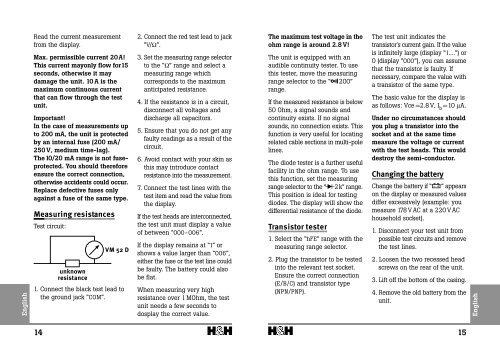
Measuring resistances<br />
Test circuit:<br />
unknown<br />
resistance<br />
<strong>VM</strong> <strong>52</strong> D<br />
1. <strong>Co</strong>nnect the black test lead to<br />
the ground jack “COM”.<br />
2. <strong>Co</strong>nnect the red test lead to jack<br />
“V/Ω”.<br />
3. Set the measuring range selector<br />
to the “Ω” range and select a<br />
measuring range which<br />
corresponds to the maximum<br />
anticipated resistance.<br />
4. If the resistance is in a circuit,<br />
disconnect all voltages and<br />
discharge all capacitors.<br />
5. Ensure that you do not get any<br />
faulty readings as a result of the<br />
circuit.<br />
6. Avoid contact with your skin as<br />
this may introduce contact<br />
resistance into the measurement.<br />
7. <strong>Co</strong>nnect the test lines with the<br />
test item and read the value from<br />
the display.<br />
If the test heads are interconnected,<br />
the test unit must display a value<br />
of between “000-006”.<br />
If the display remains at “1” or<br />
shows a value larger than “006”,<br />
either the fuse or the test line could<br />
be faulty. The battery could also<br />
be flat.<br />
When measuring very high<br />
resistance over 1 MOhm, the test<br />
unit needs a few seconds to<br />
dosplay the correct value.<br />
The maximum test voltage in the<br />
ohm range is around 2.8 V!<br />
The unit is equipped with an<br />
audible continuity tester. To use<br />
this tester, move the measuring<br />
range selector to the “ 200”<br />
range.<br />
If the measured resistance is below<br />
50 Ohm, a signal sounds and<br />
continuity exists. If no signal<br />
sounds, no connection exists. This<br />
function is very useful for locating<br />
related cable sections in multi-pole<br />
lines.<br />
The diode tester is a further useful<br />
facility in the ohm range. To use<br />
this function, set the measuring<br />
range selector to the “ 2k” range.<br />
This position is ideal for testing<br />
diodes. The display will show the<br />
differential resistance of the diode.<br />
Transistor tester<br />
1. Select the “hFE” range with the<br />
measuring range selector.<br />
2. Plug the transistor to be tested<br />
into the relevant test socket.<br />
Ensure the correct connection<br />
(E/B/C) and transistor type<br />
(NPN/PNP).<br />
The test unit indicates the<br />
transistor's current gain. If the value<br />
is infinitely large (display “1....”) or<br />
0 (display “000”), you can assume<br />
that the transistor is faulty. If<br />
necessary, compare the value with<br />
a transistor of the same type.<br />
The basic value for the display is<br />
as follows: Vce =2.8 V, I b =10 µA.<br />
Under no circumstances should<br />
you plug a transistor into the<br />
socket and at the same time<br />
measure the voltage or current<br />
with the test heads. This would<br />
destroy the semi-conductor.<br />
Changing the battery<br />
Change the battery if “ ” appears<br />
on the display or measured values<br />
differ excessively (example: you<br />
measure 178 V AC at a 220 V AC<br />
household socket).<br />
1. Disconnect your test unit from<br />
possible test circuits and remove<br />
the test lines.<br />
2. Loosen the two recessed head<br />
screws on the rear of the unit.<br />
3. Lift off the bottom of the casing.<br />
4. Remove the old battery from the<br />
unit.<br />
14<br />
15