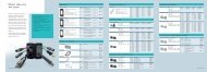
Download installation instruction, deutsch/englisch (0,40 MB)
Download installation instruction, deutsch/englisch (0,40 MB)
Download installation instruction, deutsch/englisch (0,40 MB)

Sie wollen auch ein ePaper? Erhöhen Sie die Reichweite Ihrer Titel.
YUMPU macht aus Druck-PDFs automatisch weboptimierte ePaper, die Google liebt.
DE<br />
Typ<br />
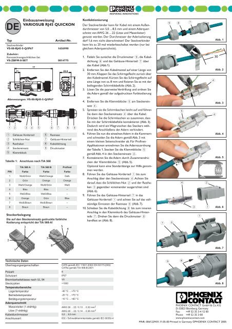
Einbauanweisung<br />
VARIOSUB RJ45 QUICKON<br />
Artikel-Nr.<br />
Steckverbinder<br />
VS-08-RJ45-5-Q/IP67 1656990<br />
Konfektionierung<br />
Der Steckverbinder kann für Kabel mit einem Außendurchmesser<br />
von 5,0 ... 8,5 mm und einem Aderquerschnitt<br />
von AWG 26 ... 22 (Litze und Massivleiter)<br />
genutzt werden. Der Durchmesser der Aderisolierung<br />
darf 1,6 mm nicht überschreiten! Der Steckverbinder<br />
kann bis zu 20 mal wiederbeschaltet werden (nur bei<br />
gleichem Aderquerschnitt).<br />
9 8 7<br />
Abb. 1<br />
Zubehör:<br />
Kennzeichnungsschildchen-Set<br />
VS-ZBFM-8-SET 0814775<br />
Ø18,5<br />
77<br />
11 22,8<br />
Abmessungen: VS-08-RJ45-5-Q/IP67<br />
12 34 5 6 7 8 9<br />
1 Gehäuse-Vorderteil 6 Rastnase<br />
2 Schildchen-Nut 7 Gehäuse-Hinterteil<br />
3 Rasthaken 8 Kabeldichtung<br />
4 Steckereinsatz 9 Druckmutter<br />
5 Klemmblock<br />
Tabelle 1: Anschluss nach TIA 568<br />
TIA 568 A TIA 568 B Profinet<br />
PIN Farbe Farbe Farbe<br />
1 Weiß/Grün Weiß/Orange Gelb<br />
2 Grün Orange Orange<br />
3 Weiß/Orange Weiß/Grün Weiß<br />
4 Blau Blau –<br />
5 Weiß/Blau Weiß/Blau –<br />
6 Orange Grün Blau<br />
7 Weiß/Braun Weiß/Braun –<br />
8 Braun Braun –<br />
Steckerbelegung<br />
Die auf den Steckereinsatz gedruckte farbliche<br />
Kodierung entspricht der TIA 568-A!<br />
3<br />
5<br />
4<br />
6<br />
38,4<br />
1. Fädeln Sie zunächst die Druckmutter 9, die Kabeldichtung<br />
8 und das Gehäuse-Hinterteil 7 über<br />
das Kabel (Abb.1).<br />
2. Entfernen Sie den Kabelmantel auf einer Länge von<br />
30 mm. Klappen Sie das Schirmgeflecht zurück über<br />
den Kabelmantel. Kürzen Sie das Schirmgeflecht auf<br />
eine Länge von ca. 8 mm und fixieren Sie es mit der<br />
beiliegenden Schirmklebefolie (Abb. 2).<br />
3. Lösen Sie die paarweise Verdrillung und ordnen Sie<br />
die Adern gemäß der aufgedruckten Farbkodierung<br />
an.<br />
4. Entfernen Sie die Klemmblöcke 5 am Steckereinsatz<br />
4.<br />
5. Spreizen sie die Schirmlaschen leicht auf und führen<br />
Sie dann den Steckereinsatz 4 über das Kabel.<br />
Drücken Sie die Schirmlaschen so zusammen, dass<br />
Sie mit der Schirmklebefolie kontaktieren (Abb. 3).<br />
Dadurch wird ein Wegrutschen des Steckers während<br />
des Anschließens der Adern verhindert.<br />
6. Führen Sie nun die einzelnen Adern in die Kammern<br />
und schneiden Sie die Adern gemäß Abb. 3 mit<br />
einem kleinen Seitenschneider ab. Für Profinet-<br />
Applikationen entnehmen Sie die Adernzuordnung<br />
der Tabelle 1. Stecken Sie die Klemmblöcke 5<br />
gemäß Abb. 4 in den Steckereinsatz 4.<br />
7. Kontaktieren Sie die Adern durch Zusammendrücken<br />
der Klemmblöcke 5 (Abb. 5).<br />
Optional kann eine Standardzange zur Hilfe genommen<br />
werden.<br />
8. Führen Sie das Gehäuse-Vorderteil 1 bis zum<br />
Anschlag über den Steckereinsatz 4. Achten Sie<br />
darauf, dass die Schildchen-Nut 2 und der Rasthaken<br />
3 gegenüber voneinander ausgerichtet sind<br />
(Abb. 6).<br />
9. Führen Sie das Gehäuse-Hinterteil 7 in das<br />
Gehäuse-Vorderteil 1 und achten Sie auf das vollständige<br />
Einrasten der Rastnase 6 (Abb. 7).<br />
10. Schieben Sie die Kabeldichtung 8 bis zum inneren<br />
Anschlag in den Klemmkorb des Gehäuse-Hinterteils<br />
7. Drehen Sie dann die Druckmutter 9<br />
handfest an (Abb. 8).<br />
7 6<br />
5<br />
4<br />
2<br />
3 1<br />
1<br />
4<br />
30<br />
Abb. 2<br />
4<br />
Abb. 3<br />
Abb. 4<br />
Abb. 5<br />
Abb. 6<br />
2<br />
1<br />
Technische Daten<br />
7<br />
8<br />
Übertragungseigenschaften CAT5 gemäß IEC 11801:2002/ EN 50173:2002;<br />
CAT5e gemäß TIA 568-B:2001<br />
Polzahl 8<br />
Schutzart<br />
IP67<br />
Brennbarkeitsklasse nach UL 94<br />
V0<br />
Steckzyklen >1000<br />
Temperaturbereiche<br />
Lagertemperatur -<strong>40</strong> °C ... +70 °C<br />
Betriebstemperatur -20 °C ... +70 °C<br />
Betätigungstemperatur -10 °C ... +60 °C<br />
Aderquerschnitt<br />
Massivleiter (1-drähtig) AWG 26 ... 22 / 0,13 ... 0,32 mm 2<br />
Litze (7-drähtig) AWG 26 ... 22 / 0,14 ... 0,36 mm 2<br />
Kabeldurchmesser<br />
5,0 ... 8,5 mm<br />
Anschlussart IDC / Schneidklemmkontakte gemäß IEC 60352-4<br />
9 8<br />
Abb. 7<br />
Abb. 8<br />
PHOENIX CONTACT GmbH & Co. KG<br />
D-32823 Blomberg, Germany<br />
Fax: +49 52 35 3-4 12 00<br />
Phone: +49 52 35 3-00<br />
www.phoenixcontact.com<br />
MNR. 0061229/01.11.05-00 Printed in Germany ©PHOENIX CONTACT 2005<br />
7
EN<br />
Type<br />
Installation <strong>instruction</strong>s<br />
VARIOSUB RJ45 QUICKON<br />
Order No.<br />
Plug connector<br />
VS-08-RJ45-5-Q/IP67 1656990<br />
Assembly<br />
The plug connector can be used for cables with an<br />
external diameter of 5.0 ... 8.5 mm and a core cross<br />
section of AWG 26 ... 22 (stranded and solid<br />
conductors). The diameter of the core insulation must<br />
not exceed 1.6 mm! The plug connector can be<br />
reconnected up to 20 times over (only with the same<br />
core cross section).<br />
9 8 7<br />
Fig. 1<br />
Accessories:<br />
Marker label set<br />
VS-ZBFM-8-SET 0814775<br />
Ø18,5<br />
77<br />
11 22,8<br />
Dimensions: VS-08-RJ45-5-Q/IP67<br />
12 34 5 6 7 8 9<br />
1 Front part of the housing 6 Engagement nose<br />
2 Marker groove 7 Rear part of the housing<br />
3 Locking clip 8 Cable seal<br />
4 Plug insert 9 Pressure nut<br />
5 Termination block<br />
Table 1: Connection in acc. with TIA 568<br />
TIA 568 A TIA 568 B Profinet<br />
PIN Color Color Color<br />
1 White/green White/orange Yellow<br />
2 Green Orange Orange<br />
3 White/orange White/green White<br />
4 Blue Blue –<br />
5 White/blue White/blue –<br />
6 Orange Green Blue<br />
7 White/brown White/brown –<br />
8 Brown Brown –<br />
38,4<br />
1. First slide the pressure nut 9, the cable seal 8<br />
and the rear part of the housing 7 over the cable<br />
(fig.1).<br />
2. Strip the cable sheath over a length of 30 mm. Fold<br />
back the braided shield over the cable sheath. Trim<br />
the braided shield to a length of approx. 8 mm and<br />
fix it with the enclosed adhesive shielding foil<br />
(fig. 2).<br />
3. Untwist the twisted pairs and arrange the cores<br />
according to the imprinted color coding.<br />
4. Remove the termination blocks 5 from the plug<br />
insert 4.<br />
5. Slightly separate the shielding lugs and then slide<br />
the plug insert 4 onto the cable. Press the shielding<br />
lugs together so that they make contact with<br />
the adhesive shielding foil (fig. 3). This prevents the<br />
plug from slipping back when the cores are being<br />
connected.<br />
6. Guide the individual cores into the chambers and<br />
trim the cores according to fig. 3 using a small<br />
diagonal cutter. For Profinet applications, see table 1<br />
for the core assignment. Plug the termination<br />
blocks 5 into the plug insert 4 according to<br />
fig. 4.<br />
7. Contact the cores by pressing the termination<br />
blocks 5 together (fig. 5).<br />
Alternatively, standard pliers can be used.<br />
8. Slide the front part of the housing 1 as far as it will<br />
go into the plug insert 4. Ensure that the marker<br />
groove 2 and locking clip 3 are opposite one<br />
another (fig. 6).<br />
9. Slide the rear part of the housing 7 into the<br />
front part of the housing 1 and ensure that the<br />
engagement nose 6 snaps in completely (fig. 7).<br />
10. Push the cable seal 8 as far as it will go into the<br />
clamping cage of the rear part of the housing 7.<br />
Tighten the pressure nut 9 firmly by hand (fig. 8).<br />
5<br />
4<br />
2<br />
3 1<br />
4<br />
30<br />
Fig. 2<br />
4<br />
Fig. 3<br />
Fig. 4<br />
Fig. 5<br />
Fig. 6<br />
Connector pin assignment<br />
The color coding printed on the plug insert<br />
corresponds to TIA 568-A!<br />
3<br />
5<br />
6<br />
4<br />
7 6<br />
1<br />
2<br />
1<br />
Technical data<br />
Transmission properties<br />
7<br />
8<br />
CAT5 in acc. with IEC 11801:2002/ EN<br />
50173:2002; CAT5e in acc. with TIA 568-B:2001<br />
No. of pos. 8<br />
Degree of protection<br />
IP67<br />
Inflammability class in acc. with UL 94 V0<br />
Insertion/withdrawal cycles >1000<br />
Temperature ranges<br />
Storage temperature -<strong>40</strong> °C ... +70 °C<br />
Operating temperature -20 °C ... +70 °C<br />
Triggering temperature -10 °C ... +60 °C<br />
Conductor cross section<br />
Solid conductors (1-wire) AWG 26 ... 22 / 0.13 ... 0.32 mm 2<br />
Stranded conductors (7-wire) AWG 26 ... 22 / 0.14 ... 0.36 mm 2<br />
Cable diameter<br />
5.0 ... 8.5 mm<br />
Connection method<br />
IDC / insulation displacement contacts in acc. with<br />
9 8<br />
7<br />
Fig. 7<br />
Fig. 8<br />
PHOENIX CONTACT GmbH & Co. KG<br />
D-32823 Blomberg, Germany<br />
Fax: +49 52 35 3-4 12 00<br />
Phone: +49 52 35 3-00<br />
www.phoenixcontact.com<br />
IEC 60352-4 MNR. 0061229/01.11.05-00 Printed in Germany ©PHOENIX CONTACT 2005