FWX SOLARTRONIC® Frischwasserstation mit ... - Clage GmbH
FWX SOLARTRONIC® Frischwasserstation mit ... - Clage GmbH
FWX SOLARTRONIC® Frischwasserstation mit ... - Clage GmbH

Sie wollen auch ein ePaper? Erhöhen Sie die Reichweite Ihrer Titel.
YUMPU macht aus Druck-PDFs automatisch weboptimierte ePaper, die Google liebt.
02.11<br />
<strong>FWX</strong> SOLARTRONIC ®<br />
<strong>Frischwasserstation</strong> <strong>mit</strong> integriertem Durchlauferhitzer zur Nacherwärmung<br />
Gebrauchsanleitung für den Anwender<br />
Fresh water station with integrated instantaneous water heater for top-up heating<br />
Operating instructions for the user<br />
DE<br />
EN
<strong>FWX</strong> SOLARTRONIC<br />
1. Übersichtsdarstellung 1. Overview<br />
Bei Ersatzteilbestellungen stets Gerätetyp<br />
und Serien nummer angeben!<br />
2<br />
When ordering spare parts, please always specify the<br />
appliance model and serial number.<br />
Frischwassereinheit / Fresh water unit Durchlauferhitzereinheit /<br />
Instantaneous hot water unit
1. Übersichtsdarstellung 1. Overview<br />
Bei Ersatzteilbestellungen stets Gerätetyp<br />
und Serien nummer angeben!<br />
Anschluss I (grün):<br />
Kugelhahn Kaltwasserzulauf ¾“ IG<br />
Connection I (green):<br />
Ball valve cold water ¾“ IG<br />
Filtersieb<br />
Filter sieve<br />
Temperaturfühler<br />
Kaltwassereinlauf T1<br />
Temperature sensor cold<br />
water inlet T1<br />
Elektronischer Regler<br />
<strong>Frischwasserstation</strong><br />
Control unit fresh water<br />
station<br />
Primärkreispumpe<br />
Pump group<br />
Rückschlagventil<br />
Nonreturn valve<br />
Anschluss III (blau):<br />
Kugelhahn Pufferspeicher<br />
Rücklauf ¾“ IG<br />
Connection III (blue):<br />
Ball valve buffer tank<br />
advance ¾“ IG<br />
6<br />
5<br />
4<br />
3<br />
2<br />
1<br />
7<br />
16 Zugentlastung für<br />
400 V-Kabel<br />
Stress relief<br />
for 400 V cable<br />
3<br />
When ordering spare parts, please always specify the<br />
appliance model and serial number.<br />
8 Anschluss IV (rot):<br />
Kugelhahn Pufferspeicher Vorlauf ¾“ IG<br />
Connection IV (red):<br />
Ball valve buffer tank advance ¾“ IG<br />
9 Manueller Entlüfter<br />
Air vent<br />
10 Durchflussmesser<br />
<strong>Frischwasserstation</strong><br />
Flow sensor fresh water<br />
station<br />
11 Plattenwärmetauscher<br />
Heat exchanger<br />
12 Temperaturfühler<br />
Warmwasser Auslauf T3<br />
Temperature sensor<br />
potable water outlet T3<br />
13 Temperaturfühler Vorlauf<br />
Pufferspeicher T2<br />
Temperature sensor buffer<br />
tank advance T2<br />
14 Anschluss II (grün):<br />
Warm wasserauslauf<br />
¾“ IG<br />
Connection II (green):<br />
ot water outlet ¾“ IG<br />
15 Zugentlastung für 230 V-Kabel<br />
Stress relief for 230 V cable
<strong>FWX</strong> SOLARTRONIC<br />
1. Übersichtsdarstellung 1. Overview<br />
Bei Ersatzteilbestellungen stets Gerätetyp<br />
und Serien nummer angeben!<br />
DSX-Gerätehaube<br />
DSX hood<br />
82503<br />
Rückflussverhinderer<br />
Non-return valve<br />
82246<br />
Durchflussgeber<br />
Flow sensor<br />
82526<br />
Temperaturfühler-Set<br />
Thermal sensor set<br />
82512<br />
Heizelement <strong>mit</strong><br />
Druckschalter<br />
Heating element with<br />
pressure switch<br />
82537<br />
STDB<br />
STDB<br />
82538<br />
Temperaturfühler-Set<br />
Temperature sensor set<br />
82512<br />
Auslaufrohr<br />
Outlet pipe<br />
9550-55401<br />
9<br />
8<br />
7<br />
3<br />
6<br />
5<br />
3<br />
2<br />
4<br />
When ordering spare parts, please always specify the<br />
appliance model and serial number.<br />
19 RS232 - Galvanische Trennungsplatine<br />
RS232 - galvanic disjunction item<br />
11 Geräteunterteil<br />
Bottom part<br />
82505<br />
12 DSX-Verbindungsrohr<br />
DSX connecting pipe<br />
82590<br />
13 Elektronikabdeckung<br />
PCB cover<br />
82580<br />
14 Klapphalter<br />
Control panel support<br />
82573<br />
15 Anschlussklemme<br />
Connecting terminal<br />
82572<br />
16 <strong>FWX</strong> Solartronic-Bedienfeld<br />
Control panel<br />
82551<br />
17 Einlaufrohr<br />
Inlet pipe<br />
9550-55400<br />
18 Rahmen<br />
Frame<br />
82571
2. Inhaltsverzeichnis<br />
1. Übersichtsdarstellung ...............................2<br />
2. Inhaltsverzeichnis ..................................5<br />
3. Umwelt und Recycling ..............................5<br />
4. Sicherheitshinweise ................................6<br />
5. Technische Daten ..................................7<br />
6. Abmessungen .....................................8<br />
7. Installation .......................................9<br />
9. Elektroanschluss (nur durch den Fachmann) ............ 13<br />
10. Erstinbetriebnahme ..............................15<br />
11. Wartungsarbeiten ................................18<br />
3. Umwelt und Recycling<br />
Ihr Produkt wurde aus hochwertigen Materialien und Komponenten<br />
entwickelt und hergestellt, die recycelbar und wiederverwendbar<br />
sind. Dieses Symbol auf Produkten und / oder<br />
begleitenden Dokumenten bedeutet, dass elektrische und<br />
elek tronische Produkte am Ende ihrer Lebensdauer vom Hausmüll<br />
getrennt entsorgt werden müssen. Bringen Sie bitte diese<br />
Produkte für die Behandlung, Rohstoffrückgewinnung und<br />
Recycling zu den eingerichteten kommunalen Sammelstellen<br />
bzw. Werkstoffsammelhöfen, die diese Geräte kostenlos entgegen<br />
nehmen. Die ordnungsgemäße Entsorgung dieses<br />
Produktes dient dem Umweltschutz und verhindert mögliche<br />
schädliche Auswirkungen auf Mensch und Umwelt, die sich aus<br />
einer unsachgemäßen Handhabung der Geräte am Ende ihrer<br />
Lebensdauer ergeben könnten.<br />
Genauere Informationen zur nächstgelegenen Sammelstelle<br />
bzw. Recyclinghof erhalten Sie bei Ihrer Gemeindeverwaltung.<br />
Geschäftskunden: wenn Sie elektrische und elektronische Geräte<br />
entsorgen möchten, treten Sie bitte <strong>mit</strong> Ihrem Händler oder<br />
Lieferanten in Kontakt. Diese halten weitere Informationen für<br />
Sie bereit. Dieses Symbol ist nur in der Europäischen Union gültig.<br />
5<br />
3. Environment and recycling<br />
2. Contents<br />
1. Overview ........................................2<br />
3. Environment and recycling ........................... 5<br />
2. Contents .........................................5<br />
4. Safety instructions ................................. 6<br />
5. Technical specifications ............................. 7<br />
6. Dimensions ......................................8<br />
7. Installation .......................................9<br />
9. Electrical connection (only by a specialist) .............. 13<br />
10. Initial operation .................................15<br />
11. Maintenance ...................................18<br />
This symbol on the products and / or accompanying<br />
documents means that used electrical<br />
and electronic products should not be<br />
mixed with general household waste. For<br />
proper treatment, recovery and recycling,<br />
please take these products to designated collection points where<br />
they will be accepted on a free of charge basis. Alternatively, in<br />
some countries you may be able to return your products to your<br />
local retailer upon the purchase of an equivalent new product.<br />
Disposing of this product correctly will help to save valuable<br />
resources and prevent any potential negative effects on human<br />
health and the environment which could otherwise arise from<br />
inappro priate waste handling. Please contact your local authority<br />
for further details of your nearest designated collection point.<br />
Penalties may be applicable for incorrect disposal of this waste,<br />
in accordance with national legislation. If you are a business user<br />
and you wish to discard electrical and electronic equipment, please<br />
contact your dealer or supplier for further information.<br />
This symbol is only valid in the European Union.
<strong>FWX</strong> SOLARTRONIC<br />
4. Sicherheitshinweise 4. Safety instructions<br />
Montage, erste Inbetriebnahme und Wartung dieses Gerätes<br />
dürfen nur durch einen anerkannten Fachhand werksbetrieb<br />
erfolgen, der dabei für die Beachtung der bestehenden<br />
Normen und Installationsvorschriften voll verantwortlich<br />
ist. Wir übernehmen keine Haftung für Schäden, die durch<br />
Nichtbeachtung dieser Anleitung entstehen!<br />
• Benutzen Sie das Gerät nur, nachdem es korrekt installiert wurde<br />
und wenn es sich in technisch einwandfreiem Zustand befindet.<br />
• Das Gerät ist nur für den Hausgebrauch und ähnliche Zwecke<br />
innerhalb geschlossener und frostfreier Räume geeignet und darf<br />
nur zum Erwärmen von Trinkwasser verwendet werden.<br />
• Das Gerät darf niemals Frost ausgesetzt werden.<br />
• Das Gerät muss dauerhaft und zuverlässig an den Schutzleiter<br />
angeschlossen werden.<br />
• Der auf dem Typenschild angegebene minimale spezifische<br />
Wasser widerstand darf nicht unterschritten werden.<br />
• Der auf dem Typenschild angegebene maximale Wasserdruck darf<br />
zu keinem Zeitpunkt überschritten werden.<br />
• Vor der ersten Inbetriebnahme sowie nach jeder Entleerung (z.B.<br />
durch Arbeiten in der Wasserinstallation oder wegen Frostgefahr<br />
oder Wartung) muss das Gerät gemäß den Hinweisen in der<br />
Anleitung ordnungsgemäß entlüftet werden.<br />
• Öffnen Sie niemals das Gerät, ohne vorher die Stromzufuhr zum<br />
Gerät dauerhaft unterbrochen zu haben.<br />
• Nehmen Sie am Gerät oder an den Elektro- und Wasserleitungen<br />
keine technischen Änderungen vor.<br />
• Beachten Sie, dass Wassertemperaturen über ca. 43 °C<br />
besonders bei Kindern als heiß empfunden werden und ein<br />
Verbrennungsgefühl hervorrufen können. Bedenken Sie, dass<br />
nach längerer Durchlaufzeit auch die Armaturen entsprechend<br />
heiß werden. Bei kleinen Zapfmengen von unter 1,5 Liter/min<br />
kann die Warmwassertemperatur schwanken. Vermeiden Sie kleine<br />
Zapfmengen.<br />
• Die Wassereinlauftemperatur darf nicht höher als 70 °C sein.<br />
Diese Temperaturbegrenzung wird über die Frischwasser einheit<br />
der <strong>FWX</strong> SOLARTRONIC im Regel betrieb sicher gestellt. WICHTIG:<br />
Die Speichermaximaltemperatur darf 80°C nicht überschreiten.<br />
• Nach einem Stromausfall oder 230 V Wiederanschluss der<br />
Station startet ein Spül- und Entlüftungsprogramm der<br />
Frischwassereinheit über 60 Sekunden. Während dieser Zeit<br />
fördert die Primärkreispumpe <strong>mit</strong> 100% Förderleistung.<br />
Warmwasseraustrittstemperatur kann in dieser Zeitspanne nicht<br />
reguliert werden.<br />
• Im Störungsfall schalten Sie sofort die Sicherungen<br />
aus. Bei einer Undichtigkeit am Gerät schließen Sie<br />
sofort die Kaltwasserzuleitung. Lassen Sie die Störung<br />
nur vom Werkskundendienst oder einem anerkannten<br />
Fachhandwerksbetrieb beheben.<br />
• Dieses Gerät ist nicht dafür bestimmt durch Personen (einschließlich<br />
Kinder) <strong>mit</strong> eingeschränkten physischen, sensorischen oder<br />
geistigen Fähigkeiten oder mangels Erfahrung und/oder mangels<br />
Wissen benutzt zu werden, es sei denn sie werden durch eine für<br />
ihre Sicherheit zuständige Person beaufsichtigt oder erhielten von<br />
ihr Anweisungen wie das Gerät zu benutzen ist. Kinder sollten<br />
beaufsichtigt werden, um sicherzustellen, dass sie nicht <strong>mit</strong> dem<br />
Gerät spielen.<br />
6<br />
Installation, initial operation and maintenance of this appliance<br />
must only be conducted by an authorised professional,<br />
who will then be responsible for adherence to applicable<br />
standards and installation regulations. We assume no liability<br />
for any damages caused by failure to observe these instructions.<br />
• Do not use the appliance until it has been correctly installed and<br />
unless it is in perfect working order.<br />
• The appliance is only suitable for domestic use and similar applications<br />
inside closed, frost-free rooms, and must only be used to<br />
heat incoming water from mains supply.<br />
• The appliance must never be exposed to frost.<br />
• The appliance must be connected to the protective conductor.<br />
• The minimal specific water resistance must not fall below the<br />
value stated on the label.<br />
• The maximum water pressure must not exceed the value on the<br />
label.<br />
• Before commissioning for the first time and each time the appliance<br />
is emptied (e.g. due to work on the plumbing system, if<br />
there is a risk of freezing or in case of maintenance), the appliance<br />
must be vented correctly in accordance with the instructions<br />
in this manual.<br />
• Do not remove the front cover under any circumstances before<br />
switching off the mains electrical supply to the unit.<br />
• Never make technical modifications, either to the appliance itself<br />
or the electrical leads and water pipes.<br />
• Pay attention to the fact that water temperatures in excess of<br />
approx. 43 °C are perceived as hot, especially by children, and<br />
may cause a feeling of burning. Please note that the fittings and<br />
taps may be very hot when the appliance has been in use for<br />
some time. At small tapping rates below 1,5 l/min high temperature<br />
deviations are possible. Please avoid such small tapping<br />
rates.<br />
• Water inlet temperature must not exceed 70 °C. This temperature<br />
decrease is ensured under normal operation conditions by the<br />
fresh water unit. IMPORTANT: The maximum temperature of the<br />
solar buffer tank shall not exceed 80 °C.<br />
• After an electrical power outage or a reconnection of the 230 V<br />
connection, the fresh water station starts with a purging programme<br />
for 60 secondss. During this time the outlet temperature<br />
is not adjustable.<br />
• In case of malfunction, disconnect the fuses immediately. In case<br />
of leaks, cut off the cold water supply instantly. Repairs must only<br />
be carried out by the customer service department or an authorised<br />
professional.<br />
• This appliance must not be used by any person (including children)<br />
with li<strong>mit</strong>ed physical, sensorial or mental abilities or failing<br />
experience and/or knowledge unless they are supervised by a<br />
person responsible for their safety or received instructions about<br />
how to use the appliance.Children should be supervised in order<br />
to make sure that they do not play with the appliance.
Typ <strong>FWX</strong> SOLARTRONIC ® Model<br />
Bestell-Nr. 5100-51095 Art.no.<br />
Nennleistung / -strom 18 kW..27 kW (26 A..39 A) Rated capacity / rated current<br />
Gewählte/r Leistung/strom<br />
18 kW (26 A) 21 kW (30 A) 24 kW (35 A) 27 kW (39 A) Chosen capacity / current<br />
Elektroanschluss 3/PE 380..415 V AC / 230 V AC<br />
3/PE 400 V AC /<br />
230 V AC<br />
Electrical connection<br />
Erforderlicher<br />
Leiterquerschnitt<br />
4,0 mm2 4,0 mm2 6,0 mm2 6,0 mm2 Minimum required<br />
cable size<br />
Warmwasserleistung<br />
(l/min)<br />
max. bei ∆t = 28 K<br />
max. bei ∆t = 38 K<br />
7<br />
Hot water<br />
(l/min)<br />
max. at ∆t = 28 K<br />
max. at ∆t = 38 K<br />
9,2<br />
10,7<br />
12,3<br />
13,8<br />
6,8<br />
7,9<br />
9,0<br />
10,2<br />
Nenninhalt 2,8 l Rated volume<br />
Bauart geschlossen, 1 MPa (10 bar) Nennüberdruck / Pressure type 1 MPa (10 bar) Type<br />
Maximal zulässiger<br />
Betriebsdruck Primärseite<br />
3 bar Max. pressure primary side<br />
Maximal zulässige<br />
Temperatur Primärseite<br />
80 °C<br />
Max. temperature<br />
primary side<br />
Heizsystem Blankdraht IES ® / bare wire heating system IES ® Heating system<br />
Einsatzbereich bei 15 °C:<br />
spez. Wasserwiderstand<br />
spez. elektr. Leitfähigkeit<br />
≥ 1100 Ωcm<br />
≤ 90 mS/m<br />
@ 15 °C:<br />
Required spec. water resistance<br />
Spec. electrical conductivity<br />
Einschaltwassermenge 2,5 l/min<br />
Required flow rate to switch<br />
on<br />
Einstellbare Temperaturen 30 °C – 60 °C Temperature range<br />
Wasseranschluss 4× IG ¾“ Water connection<br />
Gewicht (<strong>mit</strong><br />
Wasserfüllung)<br />
23 kg<br />
Weight (when filled with<br />
water)<br />
Volumenstrom l/min<br />
5. Technische Daten 5. Technical specifications<br />
Schutzart / Sicherheit<br />
14<br />
12<br />
10<br />
8<br />
6<br />
4<br />
2<br />
0<br />
IP 21<br />
0,5 1,0 1,5 2,0 2,5 3,0 3,5 4,0<br />
Differenzdruck bar<br />
Type of protection / safety<br />
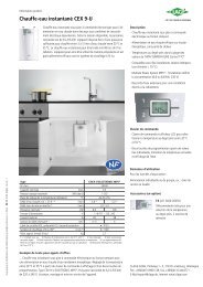
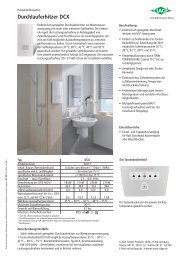
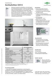
Bild 1:<br />
Durchflussmenge der <strong>FWX</strong> SOLARTRONIC in<br />
Abhängigkeit des Vordrucks (Kaltwasseranschluss)<br />
Fig. 1:<br />
Flow rate of the <strong>FWX</strong> SOLARTRONIC in accordance<br />
to the upstream pressure of the cold water<br />
inlet
<strong>FWX</strong> SOLARTRONIC<br />
379,5<br />
6. Abmessungen 6. Dimensions<br />
71,5<br />
115,50<br />
88<br />
8<br />
256<br />
231,00<br />
71,50 88,00<br />
44,00<br />
Zum Bohren der Löcher für die<br />
Befestigung der <strong>Frischwasserstation</strong><br />
verwenden Sie bitte die beigelegte<br />
Montageschablone und einen 8 mm-<br />
Bohrer.<br />
Achten Sie darauf, dass die Wand tragfähig<br />
ist. Gegebenenfalls muss bauseits<br />
entsprechend der örtlichen Begebenheiten<br />
die Tragfähigkeit der Wand erhöht werden.<br />
Please use the attached align template<br />
and 8 mm drills to anchor the station<br />
correctly.<br />
Please ensure that the wall is able to carry<br />
the weight of the station. Where required,<br />
enforce the structure.
7. Installation 7. Installation<br />
Zu beachten sind:<br />
• VDE 0100<br />
• EN 806-2<br />
• Bestimmungen der örtlichen<br />
Energie- und Wasserversorgungsunternehmen<br />
• Angaben auf Typenschild<br />
• Technische Daten<br />
• sowie alle gesetzlichen<br />
Vorschriften zur Unfallverhütung,<br />
des Umweltschutzes und der<br />
Arbeitssicherheit<br />
• die einschlägigen Sicherheitsbedingungen<br />
der DIN, EN, DVGW,<br />
TRGI, TRF und VDE<br />
• und alle am Installationsort<br />
geltenden Landesbestimmungen.<br />
Montageort<br />
• Gerät nur in einem frostfreien Raum<br />
installieren. Das Gerät darf niemals<br />
Frost ausgesetzt werden.<br />
• Das Gerät ist für eine Wandmontage<br />
vorgesehen und muss senkrecht installiert<br />
werden.<br />
• Das Gerät entspricht der Schutzart<br />
IP 21.<br />
• Um Wärme- und zu hohe Druckverluste<br />
zu vermeiden, sollte die Entfernung<br />
zwischen <strong>FWX</strong> SOLARTRONIC und<br />
Zapfstelle möglichst gering sein. Bei<br />
Leitungslängen > 14 lfdm zwischen<br />
der <strong>FWX</strong> SOLARTRONIC und der<br />
Zapf stelle wird empfohlen entweder<br />
die <strong>FWX</strong> SOLARTRONIC dezentral<br />
zu platzieren oder die Kombination<br />
<strong>Frischwasserstation</strong> <strong>mit</strong> dezentral platzierten<br />
Durchlauferhitzern direkt an der<br />
Zapfstelle einzusetzen.<br />
• Es können Wasserleitungen aus<br />
Kupfer oder Stahl ein gesetzt werden.<br />
Kunstoffrohre dürfen nur verwendet<br />
werden, wenn diese DIN 16893 Reihe 2<br />
entsprechen. Die Warmwasser leitungen<br />
müssen wärmegedämmt sein.<br />
• Der spezifische Widerstand des Wassers<br />
muss bei 15 °C mindestens 1100 Ω cm<br />
betragen. Der spezifische Widerstand<br />
des Wassers kann bei Ihrem Wasserversorgungs<br />
unternehmen erfragt<br />
werden.<br />
9<br />
The following regulations must be<br />
observed:<br />
• Installation must comply with all<br />
statutory regulations, as well as<br />
those of the local electricity and<br />
water supply companies.<br />
• The specifications on the rating<br />
plate<br />
• Technical specifications<br />
• and as well all legislative regulations<br />
of incident prevention,<br />
environmental safety and labour<br />
protection<br />
• respective safety conditions of DIN,<br />
EN, DVGW, TRGI, TRF und VDE,<br />
• and all regulations applicable in<br />
the country of use of the product.<br />
Installation site<br />
• Appliance must only be installed in<br />
frost-free rooms. Never expose appliance<br />
to frost.<br />
• The Appliance must be wall mounted<br />
and has to be installed vertically.<br />
• The appliance complies with protection<br />
type IP 21.<br />
• In order to avoid thermal and high<br />
pressure losses, the distance between<br />
the <strong>FWX</strong> SOLARTRONIC heater and the<br />
tap connection should be as small as<br />
possible. At tube distances beyound<br />
14m it is recommended to place either<br />
the <strong>FWX</strong> SOLARTRONIC shorter to the<br />
tap location or to place a <strong>FWX</strong> Fresh<br />
Water Station centrally and the instantaneous<br />
water station decentralised<br />
close to the tap locations.<br />
• Copper or steel connecting pipes may<br />
be used. Plastic pipes may only be used<br />
if they conform to DIN 16893, Series 2.<br />
The hot water pipes must be thermally<br />
insulated.<br />
• The specific resistance of the water<br />
must be at least 1100 Ω cm at 15 °C.<br />
The specific resistance can be asked for<br />
with your water distribution company.
<strong>FWX</strong> SOLARTRONIC<br />
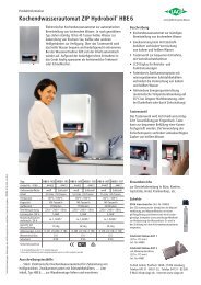
Bild 1: Thermo-Siphon-Dimensionierung<br />
Figure 1: Dimensions of the syphon<br />
Bild 2: Installation bei einem Bodenabstand > 50 cm<br />
Figure 2: Installation with ground clearance > 50 cm<br />
8-12facher Rohrdurchmesser D<br />
< 50 cm<br />
> 50 cm<br />
Bild 3: Installation bei einem Bodenabstand < 50 cm<br />
Figure 3: Installation with ground clearance < 50 cm<br />
7. Installation 7. Installation<br />
Bitte beachten Sie bei der Montage<br />
die in dieser Dokumentation genannten<br />
Sicherheitshinweise!<br />
• Unsachgemäße Montage und Betrieb<br />
der Stationen schließt alle Gewährleistungsansprüche<br />
aus<br />
• Gefährdungen durch angrenzende<br />
Bauwerkskomponenten sind zu vermeiden<br />
• Der freie Zugang zur Station und den<br />
Anschlussleitungen ist sicherzustellen<br />
• Es ist auf eine spannungsfreie<br />
Anbindung der Station zu achten<br />
• Die Station sollte nach Möglichkeit<br />
in un<strong>mit</strong>telbarer Nähe zum Heizwasserpufferspeicher<br />
montiert werden.<br />
Bitte beachten Sie die Mindest querschnitte<br />
der Rohrleitungen in Abhängigkeit<br />
der Entfernung der Station zum<br />
Pufferspeicher im Kapitel „Installation<br />
/ Hydraulischer Anschluss“.<br />
• Die Montage hat an einer tragfähigen<br />
und trocknen Wand zu erfolgen.<br />
• Ggf. ist zwischen Wand und<br />
<strong>Frischwasserstation</strong> eine Dämpfung<br />
vorzusehen, sodass Schwingungen<br />
nicht übertragen werden können.<br />
ACHTUNG!<br />
Die <strong>Frischwasserstation</strong> soll nach<br />
Möglichkeit stets in der Höhe des<br />
unteren Drittels des Speichers gesetzt<br />
werden um Eigenzirkulation und<br />
da<strong>mit</strong> Speicherauskühlungen wie auch<br />
Temperaturspitzen zu vermeiden.<br />
Sollte diese Anordnung nicht möglich<br />
sein, so wird dringend empfohlen, ein<br />
Thermosiphon am oberen Ausgang des<br />
Speichers (Anschluss IV, rot) anzubringen.<br />
Bitte beachten Sie, dass die Höhe<br />
des Thermosiphons das 8 – 12-fache des<br />
Rohrdurchmessers betragen soll.<br />
10<br />
Please follow at the assembly of the<br />
system the safety instructions of this<br />
documentation!<br />
• Improper installation, commissioning<br />
and operation of the installed unit and<br />
system exclude any guarantee claims.<br />
• Any endangerment due bordering building<br />
components has to be removed.<br />
• The free access to the station and the<br />
connection pipes has to be ensured.<br />
• The connection to the station has to be<br />
installed without persistent tension.<br />
• The station should be installed as close<br />
as possible to the buffer tank. Please<br />
ensure the minimum pipe dimension.<br />
• The station has to be mounted on a<br />
stable wall.<br />
ATTENTION!<br />
The fresh water station has to be<br />
installed as far as possible on the bottom<br />
height of the buffer tank to avoid<br />
passive circulation, tank heating losses<br />
and temperature peaks.<br />
If the installation cannot be performed<br />
below 50 cm (bottom SOLARTRONIC<br />
to bottom buffer tank) see Figure , it is<br />
urgently recommended to install a siphon<br />
at the upper height of the forward connection<br />
pipe (connection IV, red). Please<br />
ensure that the height of the siphon is 8<br />
to 12 times the installed pipe diameter.
oben / top Montageschablone / Align template<br />
379,5
unten / bottom
7. Installation 7. Installation<br />
Hydraulischer Anschluss<br />
1. Entnehmen Sie bitte die Bohrschablone<br />
in der Mitte dieser Montagenanleitung<br />
und zeichnen Sie die entsprechenden<br />
Bohrpunkte an der zu befestigenden<br />
Wand ein. Bitte beachten Sie, dass die<br />
Montage an einer tragfähigen und<br />
trocknen Wand zu erfolgen hat und die<br />
Station möglichst tief bzw. <strong>mit</strong> einem<br />
entsprechenden Syphon gesetzt werden<br />
sollte um Eigenzirkulation zu vermeiden.<br />
Bitte beachten Sie die weiteren<br />
Sicherheits,- und Montagehinweise.<br />
2. Bohren Sie dann <strong>mit</strong> einem 8 mm<br />
Bohrer die entsprechenden Bohrpunkte<br />
und setzen Sie die beigelegten Dübel<br />
ein. Drehen Sie nun die beigelegten<br />
3 Schrauben ein. Um die Station ordnungsgemäß<br />
einzuhängen lassen Sie<br />
bitte einen Abstand von ca. 4-5 mm zw.<br />
der Wand und der Kopfunterseite der<br />
Schrauben.<br />
3. Hängen Sie nun die <strong>FWX</strong> SOLAR-<br />
TRONIC in die eingeschraubten<br />
Schrauben ein. Bitte achten Sie<br />
auf einen strammen aber spannungsfreien<br />
Sitz der Station in den<br />
Aufhängungspunkten.<br />
4. Nehmen Sie nun die Anbindung <strong>mit</strong><br />
dem Speicher vor. Hierzu wird zunächst<br />
Anschluss III (blau, Pufferspeicher<br />
Rücklauf) <strong>mit</strong> dem in den unteren<br />
Bereich schichtenden Einlauf<br />
des Pufferspeichers verbunden.<br />
Anschliessend wir der Anschluss IV<br />
(rot, Pufferspeicher Vorlauf) der <strong>FWX</strong><br />
SOLARTRONIC <strong>mit</strong> dem in den oberen<br />
Bereich schichtenden Auslauf des<br />
Pufferspeichers verbunden. Hierbei<br />
wird empfohlen die Druckverluste<br />
durch großzügige Dimensionierung der<br />
Anbindungsleitungen zu minimieren.<br />
Bitte verwenden Sie bei einem einfachen<br />
Rohrleitungsabstand zw. der<br />
Station und dem Pufferspeicher folgende<br />
Rohrleitungsquerschnitte:<br />
Einfacher Abstand zwischen<br />
Solartronic und Pufferspeicher<br />
One side distance between<br />
SOLARTRONIC and buffer tank<br />
11<br />
Min. Rohrleitungs querschnitt für<br />
Kupferrohrleitung (glatt)<br />
Minimum outside tube dimension<br />
for copper tubes<br />
Hydraulic connection<br />
1. Please use drilling template out of<br />
the middle of this assembly manual<br />
and point the corresponding drilling<br />
points. Please ensure that the installation<br />
is conducted on a stable wall<br />
and is mounted as low as possible in<br />
respect to the buffer tank. Follow the<br />
advises in regards of the installation of<br />
a siphon. Please follow all safety and<br />
mounting instructions.<br />
2. Please drill then with a 8 mm drill the<br />
respective drilling points and insert<br />
the added dowel plugs. Turn now the<br />
added 3 screws. To place the station<br />
properly we recommend to let a distance<br />
of approx. 4-5 mm between the<br />
wall and bottom side of the screw<br />
heads.<br />
3. Hang now the <strong>FWX</strong> SOLARTRONIC<br />
Station into the screwed screws. Please<br />
pay attention to mount the station<br />
tough but tension free into the suspension<br />
points.<br />
4. Perform now the binding to the buffer<br />
tank. Connect connection III (blue, buffer<br />
tank return) with one of the lowest<br />
sleeve sockets of the buffer tank.<br />
Afterwards conduct the connection IV<br />
(red, buffer tank forward) to the upper<br />
area of the buffer tank. Please use the<br />
sleeve socket which taps the hottest<br />
water from the top of the tank. It is<br />
strongly recommended to avoid high<br />
pressure losses of the primary circuit.<br />
Please do not undersize the forward<br />
and return tube dimensions. Please<br />
use by one side distance between the<br />
station and the buffer tank at least following<br />
pipe dimensions:<br />
Min. Rohrleitungs querschnitt für<br />
Edelstahl wellrohr leitung<br />
Minimum inside dimension for<br />
stainless steel tubes<br />
0 – 3 m 22 mm DN 20<br />
3 – 10 m 28 mm DN 25<br />
Kontaktieren Sie den CLAGE-Kundendienst<br />
> 10 m<br />
Contact CLAGE‘s customer service.
<strong>FWX</strong> SOLARTRONIC<br />
7. Installation 7. Installation<br />
5. Stellen Sie sicher, dass die Anbindung<br />
der Rohre spannungsfrei erfolgt ist.<br />
Sollte die Station nicht auf der Höhe<br />
des unteren Drittels des Pufferspeichers<br />
angebunden werden können, so ist<br />
ein Syphon gemäß Abbildung 1 und 2<br />
einzubauen. Achten Sie darauf, dass<br />
die Kugelhähne III (blau) und IV (rot)<br />
bis zur Inbetriebnahme verschlossen<br />
bleiben.<br />
6. Nehmen Sie nun die Anbindung<br />
des Trinkwasserkreislaufs vor.<br />
Hierzu wird der Anschluss I (grün,<br />
Kaltwasseranschluss) <strong>mit</strong> der<br />
Kaltwasserleitung verbunden.<br />
ACHTUNG: am Anschluss I (grün)<br />
befindet sich ein verplombter<br />
Kugelhahn. Dieser Kugelhahn darf<br />
nur im Servicefall kurzzeitig betätigt<br />
werden zwecks Reinigung des<br />
Filtersiebes. Danach ist der Kugelhahn<br />
schnellstmöglich wieder zu öffnen und<br />
zu verplomben um ein unbeabsichtigtes<br />
Verschliessen des Kugelhahns zu<br />
verhindern. Bei Kaltwasserdrücken ><br />
10 bar ist zwingend ein Druckminderer<br />
einzusetzen. Bei Wasserhärten größer<br />
14°dH ist ein Spülhahn in den<br />
Kaltwasserzulauf und ein Spülhahn in<br />
den Warmwasserablauf einzubauen.<br />
7. Nun kann die Anbindung des<br />
Warmwasseranschlusses erfolgen<br />
(Anschluss I, grün). Stellen Sie sicher,<br />
dass die Anbindung der Rohre spannungsfrei<br />
erfolgt ist.<br />
12<br />
5. Please ensure a tension free connection<br />
of the forward and return tubes<br />
to the station. If the station is not installed<br />
at the lower height level of the<br />
buffer tank please ensure the installation<br />
of a siphon structure according to<br />
figure 1 and 2. Please ensure that the<br />
ball valves at connection III (blue) and<br />
connection IV (red) are closed until the<br />
commissioning procedure.<br />
6. Take now the binding of the potable<br />
water circuit. Therefore the connection<br />
I (green, cold water inlet) has to<br />
be connected to the existing cold water<br />
line. ATTENTION: in the connection I<br />
(green) the ball valve is sealed. The<br />
release of the sealing is only allowed<br />
in service case for a short time for the<br />
purpose of cleaning of the filter sieve.<br />
After the cleaning the ball valve has to<br />
be closed fastest possible. Additionally<br />
the sealing has to be reperformed to<br />
avoid unintentional close of the ball<br />
valve. At cold water pressure rates<br />
higher than 10 bar it is preliminary to<br />
install a pressure reducing regulator.<br />
With water hardness greater 14°dH<br />
is recommendated to install purging<br />
valves in the cold water inlet and hot<br />
water outlet.<br />
7. Now the hat water tubing can be<br />
performed to the connection I (green,<br />
hot water outlet). Please ensure that<br />
the hot tubes are connected without<br />
tension.
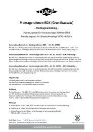
Schaltplan / Wiring diagram<br />
2<br />
1<br />
1 Elektronik / Electronic circuitry<br />
2 Heizelement / Heating element<br />
3 Sicherheitsdruckbegrenzer und<br />
Sicherheitstemperatur begrenzer /<br />
Safety pressure switch and Safety<br />
thermal cut-out<br />
4 Klemmleiste / Terminal strip<br />
3<br />
4<br />
9. Elektroanschluss (nur durch den Fachmann) 9. Electrical connection (only by a specialist)<br />
Zu beachten sind:<br />
• VDE 0100<br />
• EN806-2<br />
• Bestimmungen der örtlichen<br />
Energie- und Wasserversorgungsunternehmen<br />
• Angaben Typenschild<br />
• Technische Daten<br />
• Gerät an den Schutzleiter anschließen!<br />
Bauliche Voraussetzungen<br />
• Das Gerät muss dauerhaft an fest<br />
verlegte Leitungen angeschlossen<br />
werden. Das Gerät muss an den<br />
Schutzleiter angeschlossen werden.<br />
Kabelquerschnitt maximal 10mm2 .<br />
• Die Elektroleitungen müssen sich in<br />
einem einwandfreien Zustand befinden<br />
und dürfen nach der Montage nicht<br />
mehr berührbar sein.<br />
• Installationsseitig ist eine allpolige<br />
Trennvorrichtung <strong>mit</strong> einer Kontaktöffnungsweite<br />
von mindestens<br />
3 mm pro Pol vorzusehen (z.B. über<br />
Sicherungen).<br />
• Zur Absicherung des Gerätes ist ein<br />
Sicherungselement für Leitungsschutz<br />
<strong>mit</strong> einem dem Gerätenennstrom angepassten<br />
Auslösestrom zu montieren.<br />
Lastabwurfrelais<br />
Beim Anschluss weiterer Drehstromgeräte<br />
empfehlen wir die Verwendung eines<br />
Lastabwurfrelais für elektronische<br />
Durchlauferhitzer (CLAGE Art.Nr. 82250).<br />
Dieses wird an den Außenleiter L2 angeschlossen.<br />
LCD Beschreibung<br />
0<br />
1<br />
2<br />
Normaler Betrieb,<br />
Werkeinstellung<br />
Betrieb <strong>mit</strong> normalem<br />
Lastabwurfrelais<br />
Betrieb <strong>mit</strong> empfindlichem<br />
Lastabwurfrelais<br />
Zum Ändern der Betriebsart rufen Sie bitte<br />
zunächst das Setup-Menü auf: Drücken<br />
Sie gleichzeitig die Setup-Taste und die<br />
Service-Taste für mindes tens 3 Sekun-<br />
13<br />
Please observe:<br />
• The installation must comply with<br />
current IEC and national local regulations<br />
or any particular regulations,<br />
specified by the local electricity<br />
supply company<br />
• Observe the rating plate and technical<br />
specifications<br />
• The unit must be earthed!<br />
Structural prerequisites<br />
• The appliance must be installed via a<br />
permanent connection. Heater must<br />
be earthed! A maximum cable size of<br />
10 mm2 must be observed.<br />
• The electric wiring should not be injured.<br />
After mounting, the wiring must<br />
not be direct accessible.<br />
• An all-pole disconnecting device (e.g.<br />
via fuses) with a contact opening<br />
width of at least 3 mm per pole should<br />
be provided at the installation end.<br />
• To protect the appliance, a fuse element<br />
must be fitted with a tripping<br />
current commensurate with the nominal<br />
current of the appliance.<br />
Load shedding relay<br />
If further three-phase appliances are connected,<br />
a load shedding relay (82250)<br />
can be connected to phase conductor L2 .<br />
A special operating mode must be selected<br />
on the appli ance for this purpose. To<br />
change the operating mode, call up the<br />
setup menu first:<br />
LCD Description<br />
Normal operation,<br />
0<br />
manufacturer‘s setting<br />
Operation with normal<br />
1<br />
load shedding relay<br />
Operation with sensitive<br />
2<br />
load shedding relay<br />
Press the setup key and the service key<br />
simultaneously for at least 3 seconds,<br />
the display confirms by “Setup”.
<strong>FWX</strong> SOLARTRONIC<br />
9. Elektroanschluss (nur durch den Fachmann) 9. Electrical connection (only by a specialist)<br />
den, die Anzeige bestätigt <strong>mit</strong> »Setup«.<br />
Nach siebenmaligem Drücken der Pfeiltaste<br />
erreichen Sie das Setup-Menü für<br />
den Lastabwurf. Ein Drücken der Setup-<br />
Taste aktiviert den Verstell modus des<br />
Parameters »Last abwurf«, die Anzeige<br />
blinkt. Sie können nun <strong>mit</strong> den Pfeiltasten<br />
und zwischen den Ein stellungen<br />
»0«, »1« und »2« wählen. Ein erneuter<br />
Druck auf die Setup-Taste speichert<br />
den neuen Parameter wert.<br />
Mit der Service -Taste gelangen Sie<br />
wieder in die Normalanzeige.<br />
Zunächst ist die Betriebsart »1« zu<br />
wählen und die Funktion des Last abwurfrelais<br />
bei kleiner Geräteleistung (35 Grad<br />
Sollwert und geringe Wasser menge) zu<br />
prüfen. Kommt es zu einem Flackern des<br />
Abwurfrelais, so muss die Betriebsart »2«<br />
gewählt werden.<br />
14<br />
After pressing the arrow key seven<br />
times, you reach the setup menu for the<br />
load shedding. The setup mode of the<br />
parameter “load shedding” is activated by<br />
pressing the setup key , the display is<br />
flashing. You can now select between<br />
mode “0”, “1” and “2” with the aid of<br />
arrow key and . A new pressing on<br />
the setup key will store the new parameter<br />
value.<br />
You will get back to the normal display by<br />
pressing the service key .<br />
Operating mode 1 must be selected first,<br />
thus to check the correct operation of<br />
the load shedding relay at low appliance<br />
output (35 degree celsius setpoint and<br />
low water flow rate). Mode “2“ must be<br />
selected if the load shedding relay flickers.
Anschluss II (grün) öffnen<br />
und Trinkwasserseite<br />
spülen.<br />
Anschluss III (blau) und<br />
Anschluss IV (rot) öffnen,<br />
entlüften und 230 V<br />
Anschluss der Station<br />
vornehmen. WICHTIG:<br />
Warmwasser zapfen<br />
Vor und nach dem<br />
230 V-Anschluss <strong>mit</strong><br />
Entlüftungsschlüssel<br />
entlüften<br />
Open hot water outlet<br />
valve (green) and purge<br />
the potable water line<br />
Open connection III<br />
(blue) and connection<br />
IV (red), purge and connect<br />
to the 230 V grid.<br />
IMPORTANT: continually<br />
tap hot water<br />
Vent with venting key<br />
before and after the connection<br />
to the 230 V grid<br />
10. Erstinbetriebnahme 10. Initial operation<br />
Die Einhaltung der Erstinbetriebnahmevorschriften<br />
ist für einen korrekten<br />
Betrieb der <strong>FWX</strong> SOLARTRONIC<br />
zwingend erforderlich. Der elektrische<br />
Anschluss kann erst nach den korrekt<br />
erfolgten Inbetriebnahmeschritten<br />
erfolgen.<br />
1. Zunächst wird der Sekundärkreis d.h.<br />
die Trinkwasserseite gespült. Hierzu<br />
wird der warmwasserseitige Kugelhahn<br />
I (grün) und die Kaltwasserzuleitung<br />
geöffnet. Durch das mehrfache und<br />
langsame Öffnen und Schließen<br />
eines Warmwasserzapfventils (z.B.<br />
Waschbecken oder Dusche), wird<br />
das Gerät gefüllt und gespült bis es<br />
vollständig sekundärseitig entlüftet<br />
ist. Nach jeder Entleerung (z.B. nach<br />
Arbeiten an der Wasserinstallation,<br />
nach Wartungen oder Reparaturen<br />
etc.) muss dass Gerät vor der<br />
Wiederinbetriebnahme erneut befüllt<br />
und entlüftet werden.<br />
2. Darauffolgend wird der Primärkreis<br />
gespült. Hierzu werden die Kugelhähne<br />
des Primärkreises (Anschluss III, blau<br />
und Anschluss IV, rot) geöffnet. Der<br />
Entlüfter an der Frischwassereinheit<br />
ist zu öffnen, bis keine Luft mehr entweicht,<br />
danach den Entlüfter vorläufig<br />
schliessen. Bis zu diesem Zeitpunkt<br />
ist weder die Durchlauferhitzereinheit<br />
noch die Frischwassereinheit an ein<br />
Stromnetz angeschlossen.<br />
3. ACHTUNG: vor dem elektrischen<br />
Anschluss der <strong>Frischwasserstation</strong> an<br />
das 230-Volt-Netz ist sicherzustellen,<br />
dass eine Warmwasserzapfung<br />
stattfindet. Eine Warmwasserzapfung<br />
während der Inbetriebnahme ist bei<br />
hohen Speichertemperaturen >70°C<br />
zwingend notwendig um Schäden am<br />
Gerät zu verhindern. Im Moment des<br />
elektrischen Anschlusses (230-Volt-<br />
Stecker) der Frischwassereinheit<br />
startet ein Spülprogramm um<br />
Luft ansammlungen aus der Frischwasser<br />
station zu entfernen. Hierbei<br />
fördert die Primärkreispumpe <strong>mit</strong><br />
100 % Förderleistung bis zu 60<br />
Sekunden lang. Un<strong>mit</strong>tel bar nach dem<br />
Stromanschluss und in regelmäßigen<br />
Abständen ist der Entlüfter an der<br />
<strong>Frischwasserstation</strong> und am höchsten<br />
Punkt des Speichers zu betätigen um<br />
Restluft aus dem Primärsystem zu entfernen.<br />
15<br />
The correct commissioning procedure<br />
has to be ensured. Please strongly follow<br />
the commissioning procedure.<br />
1. The secondary circuit with potable<br />
water and the instantaneous water<br />
heater has to be commissioned first.<br />
Therefore open the ball valve at connection<br />
I (green) first. Next, open and<br />
close the hot water taping valve several<br />
times until no more air emerges<br />
from the line and all air has been eliminated<br />
from the instantaneous water<br />
heater. (In the case of after works on<br />
the water installation, after servicing<br />
or repairs the procedure has to be<br />
repeated).<br />
2. Next the primary circle has tas to be<br />
filled and vented. Therefore please<br />
open the ball valves on the primary<br />
side (connection III, blue and IV, blue).<br />
Then open the air vent of the fresh<br />
water station unit, until all air has<br />
disappeared, then preliminary close<br />
the air vent. Until this point neither the<br />
fresh water nor the instantaneous hot<br />
water unit is connected on electricity<br />
line.<br />
3. ATTENTION: Before the 230 V electric<br />
connection of the fresh water station<br />
a hot water tapping should run. This<br />
is obligatory if the buffer tank temperature<br />
is higher than 70°C to avoid<br />
damages of the system. At the moment<br />
of the electric connection (230 V plug)<br />
of the fresh water unit a purging<br />
program is starting to remove any air<br />
inclusion in the fresh water station<br />
unit. At this mode the pump group of<br />
the fresh water station unit is running<br />
at 100% for up to 60 seconds. After<br />
the purging program and in frequent<br />
intervals vent the air at the fresh water<br />
station unit and the top of the buffer<br />
tank, to ensure that any enclosed air is<br />
removed from the primary system.
<strong>FWX</strong> SOLARTRONIC<br />
®<br />
Multiple Power System:<br />
Die Nennleistung (max. Leistungsaufnahme)<br />
beträgt 27 kW bei 400 V<br />
und kann intern auf 24 kW, 21 kW<br />
oder 18 kW umgeschaltet werden!<br />
The rated capacity (max. power consumption)<br />
is 27 kW / 400 V and can be changed<br />
internally to 24 kW, 21 kW or 18 kW.<br />
10. Erstinbetriebnahme 10. Initial operation<br />
4. Jetzt kann die Durchlauferhitzereinheit<br />
entsprechend folgender Anweisungen<br />
in Betrieb genommen werden.<br />
Darauffolgend kann der 380 – 400-Volt-<br />
Anschluss gemäß folgender Seiten<br />
erfolgen.<br />
Hinweis »Leistungsumschaltung«<br />
(darf nur durch autorisierten Fachmann<br />
erfolgen, sonst erlischt die<br />
Garantie). Beim ersten Ein schalten der<br />
Versorgungsspannung muss die maxi male<br />
Geräteleistung ein ge stellt werden. Das<br />
Gerät stellt erst nach dem Einstellen der<br />
Geräte leis tung die normale Funktion zur<br />
Ver fügung.<br />
Die maximal mögliche Leis tung ist<br />
abhängig von der Instal la tions umgebung.<br />
Beachten Sie unbe dingt die Angaben in<br />
der Tabelle <strong>mit</strong> den technischen Daten,<br />
ins beson dere den notwendigen Querschnitt<br />
der elek trischen Anschluss leitung<br />
und die Absicherung. Beachten Sie zusätzlich<br />
die Vorgaben der DIN VDE 0100.<br />
5. Schalten Sie die Stromzufuhr zum<br />
Gerät ein. Die LCD-Anzeige am Gerät<br />
muss leuchten.<br />
6. Beim ersten Einschalten der Versorgungsspannung<br />
blinkt in der Anzeige<br />
der Wert »21«. Falls nicht, lesen Sie<br />
bitte den unten stehenden »Hinweis<br />
zur erneuten Inbetriebnahme«.<br />
7. Mit den Pfeiltasten und die<br />
maxi male Geräteleistung in Abhängigkeit<br />
der Installations umgebung einstellen<br />
(18, 21, 24 oder 27kW).<br />
8. Mit der Setup-Taste die Ein stel lung<br />
bestätigen. Das Gerät nimmt seinen<br />
Betrieb auf.<br />
9. Auf dem Typenschild die eingestellte<br />
Leistung kennzeichnen.<br />
10. Nach dem Einstellen der maximalen<br />
Geräteleistung wird die Wasser heizung<br />
nach ca. 30 Sekunden Wasser fluss<br />
aktiviert.<br />
16<br />
4. Now the electrical connection<br />
(380 – 400 V) of the direct water unit<br />
can be peformed. Please follow the instructions<br />
from the following pages.<br />
Note “Selection of power rating“<br />
only by authorised specialist,<br />
otherwise lapse of guarantee). Upon<br />
first connection of the appliance to the<br />
supply voltage, select the maximum<br />
power rating. Only after having set the<br />
power rating, the heater provides its standard<br />
operation mode.<br />
The maximum allowable power rating<br />
at installation site depends on the local<br />
situation. It is imperative to observe all<br />
data shown in the table “Technical specifications“,<br />
in particular the required cable<br />
size and fuse protection for the electrical<br />
connection. Moreover, the electrical installation<br />
must comply with the statutory<br />
regulations of the respective country and<br />
those of the local electricity supply company<br />
(Germany: DIN VDE 0100).<br />
5. Switch on the power supply to the<br />
appliance. The LCD display on the<br />
appliance must light up.<br />
6. When switching on the supply voltage<br />
for the first time, the value<br />
“21“ flashes in the display. If not,<br />
please carefully read the below note<br />
„Reinstallation“.<br />
7. Select the maximum allowable power<br />
rating depending on the local situation<br />
via the up and down arrow keys<br />
(18, 21, 24 or 27 kW).<br />
8. Press key to confirm the setting.<br />
The appliance starts operating.<br />
9. Mark the set power rating on the<br />
rating plate.<br />
10. After having set the maximum allowable<br />
power rating, the heating element<br />
will be activated after approx. 30 sec<br />
of water flow.
10. Erstinbetriebnahme 10. Initial operation<br />
11. Öffnen Sie das Warmwasserzapfventil.<br />
Überprüfen Sie die Funktion der<br />
Station.<br />
12. Machen Sie den Benutzer <strong>mit</strong> dem<br />
Gebrauch vertraut und übergeben<br />
Sie ihm die Gebrauchsanleitung.<br />
13. Füllen Sie die Registrierkarte aus und<br />
senden diese an den Zentralkundendienst<br />
oder registrieren Sie Ihr Gerät<br />
online auf unserer Homepage www.<br />
clage.de.<br />
Hinweis »Erneute Inbetriebnahme«<br />
Wird das Gerät nach der Erstinstallation<br />
unter einer anderen Installationsumgebung<br />
abermals in Betrieb genommen,<br />
so kann es notwendig werden, die maximale<br />
Geräteleistung zu ändern.<br />
Durch kurz zeitiges Überbrücken der<br />
beiden Stifte (siehe Bild) z.B. <strong>mit</strong> einem<br />
isolier ten Schrauben dreher (EN 60900)<br />
geht das Gerät in den Ausliefer zustand<br />
zurück. Alle Parameter werden auf<br />
Werkeinstellung gesetzt und die Heizung<br />
wird gesperrt. In der Anzeige blinkt<br />
»21«, bis die maximale Geräte leistung<br />
eingestellt wurde. Dieser Zustand bleibt<br />
beim Aus- und Ein schalten der Versorgungsspannung<br />
erhalten.<br />
Sperr-Level<br />
Der Umfang der Bedienung des Gerätes<br />
kann einge schränkt werden.<br />
Aktivierung der Sperrfunktion:<br />
1. Gewünschten Sperr-Level im Setup-<br />
Menü einstellen (siehe Kapitel<br />
»Gebrauch, Setup-Menü«)<br />
2. Gerät vom Netz trennen (z.B. durch<br />
Ausschalten der Sicherungen)<br />
3. Brücke auf die Leistungselektronik aufstecken<br />
(siehe Bild)<br />
4. Gerät wieder in Betrieb nehmen<br />
Deaktivieren der Sperrfunktion:<br />
1. Gerät vom Netz trennen (Sicherungen<br />
ausschalten)<br />
2. Brücke entfernen<br />
3. Gerät wieder in Betrieb nehmen.<br />
17<br />
11. Open the hot water tap. Check the<br />
function of the appliance.<br />
12. Explain the user how the instan taneous<br />
water heater works and hand<br />
over the operating instructions for<br />
the user.<br />
13. Fill in the guarantee registration card<br />
and send it to the CLAGE Central Custo<br />
mer Service or use the online registration<br />
on our website www.clage.com.<br />
Note “Reinstallation“<br />
In case the appliance will be commissioned<br />
again under different installation<br />
conditions than during its initial operation,<br />
it may be necessary to adapt the<br />
maximum power rating.<br />
A temporary short-circuit of the two pins,<br />
e.g. with a screwdriver acc. to EN 60900<br />
(see figure), will reset all heater parameters<br />
to works setting and lock the heating.<br />
Value “21“ flashes in the display until the<br />
maximum power rating has been selected.<br />
This condition will maintain when<br />
activating and deactivating the supply<br />
voltage.<br />
Lock level<br />
The operating mode of the appliance can<br />
be restricted.<br />
Activation of the Lock level:<br />
1. Select required level of Lock level via<br />
the setup menu (see chapter<br />
“How to use, Setup menu”)<br />
2. Disconnect the appliance from the<br />
power supply (e.g. by switching off the<br />
fuses)<br />
3. Insert the jumper on the power electronics<br />
(see picture)<br />
4. Put the appliance into operation again<br />
Deactivation of the Lock level:<br />
1. Disconnect the appliance from the<br />
power supply (e.g. by switching off the<br />
fuses)<br />
2. Remove jumper<br />
3. Put the appliance into operation again
<strong>FWX</strong> SOLARTRONIC<br />
11. Wartungsarbeiten 11. Maintenance<br />
Wartungsarbeiten dürfen nur von<br />
einem anerkannten Fachhandwerksbetrieb<br />
durchgeführt werden.<br />
Reinigung und Wechsel des<br />
Filtersiebes<br />
Der Kaltwasseranschluss der<br />
Frischwassereinheit ist <strong>mit</strong> einem<br />
Kugelhahn und einem Sieb ausgestattet.<br />
Durch Verschmutzung des Siebes kann die<br />
Warmwasserleistung vermindert werden,<br />
so dass eine Reinigung bzw. Austausch<br />
des Siebes notwendig werden können.<br />
Da gemäß DIN 1988 / EN806 eine durchgehende<br />
Absperrung der Kaltwasserseite<br />
in einer druckfesten Anlage zu verhindern<br />
sei, ist der Kugelhahn am<br />
Kaltwasseranschluss verplombt. D.h. darf<br />
die Verplombung lediglich kurzzeitig für<br />
die Reinigung oder Tausch des Filtersiebes<br />
abgenommen werden und der Kugelhahn<br />
kurzzeitig geschlossen werden. Nach der<br />
erfolgten Reinigung oder Filtertausches<br />
ist der Kugelhahn wieder zu verplomben.<br />
Der Austausch des Siebes ist wie folgt<br />
vorzunehmen.<br />
1. Schalten Sie den Durchlauferhitzer an<br />
den Haussicherungen spannungsfrei<br />
und sichern Sie diese gegen unbeabsichtigtes<br />
Wiedereinschalten.<br />
2. Schalten Sie die 230 V-Versorgung der<br />
Frischwassereinheit ab.<br />
3. Drehen Sie alle Kugelhähne des primären<br />
und sekundären Kreises der Station<br />
zu.<br />
4. Schrauben Sie die Überwurfmutter<br />
direkt unterhalb des Kugelhahns für<br />
den Kaltwasseranschluss ab und nehmen<br />
Sie das Sieb heraus.<br />
5. Das Sieb kann nun gereinigt bzw.<br />
ersetzt werden.<br />
6. Setzen Sie das Sieb wie vorgefunden<br />
zw. der Überwurfmutter und dem<br />
Kugelhahn ein und schrauben Sie diese<br />
fest an.<br />
7. Drehen Sie nun alle Kugelhähne<br />
langsam auf. Beginnen Sie dabei <strong>mit</strong><br />
dem kaltwasserseitigen Kugelhahn<br />
(Anschluss I, grün). Entlüften Sie das<br />
Gerät, in dem Sie das zugehörige<br />
Warmwasserventil mehrfach langsam<br />
öffnen und schließen, bis keine Luft<br />
mehr aus der Leitung austritt.<br />
18<br />
Maintenance work must only be conducted<br />
by an authorised professional.<br />
Cleaning and replacing the<br />
filter strainer<br />
The cold water connection (connection I)<br />
of the fresh water unit is equipped with a<br />
ball valve and a filter strainer. Soiling of<br />
the strainer may reduce the warm water<br />
output. According to German Institute<br />
for Standardization DIN1988 / EN806 an<br />
ongoing closure of a cold water inlet in a<br />
system has to be avoided. Therefore the<br />
cold water ball valve is sealed. Therefore<br />
the sealing may only be removed for short<br />
cleaning or replacing period of the filter<br />
strainer. After the cleaning or replacement<br />
of the filter the ball valve has to be closed<br />
immediately and sealed again to avoid<br />
permanent closure. Clean or replace the<br />
strainer as follows:<br />
1. De-energize the instantaneous water<br />
heater by means of the house fuses<br />
and prevent inadvertent reactivation<br />
of them.<br />
2. Switch off the 230 V connection of the<br />
fresh water station.<br />
3. Turn all ball valves of the primary and<br />
secondary circle of the station to the<br />
closed position.<br />
4. Screw the union nut directly below the<br />
ball valve for the cold water connection<br />
of and take the strainer out.<br />
5. The strainer can be cleaned or replaced<br />
now.<br />
6. After fitting of the strainer tighten the<br />
screw now.<br />
7. Turn on now all ball valves slowly on.<br />
Begin with ball valve on the cold water<br />
side (connection I, green). Vent the<br />
whole device by opening and closing<br />
one hot water valve several times until<br />
no more air emerges from the line and<br />
all air has been eliminated from the<br />
instantaneous water heater and the<br />
fresh water station unit.<br />
8. Connect the 230 V electrical line with<br />
the grid.<br />
9. Reconnect the voltage to the house<br />
fuses.
11. Wartungsarbeiten 11. Maintenance<br />
8. Schalten Sie die 230 V-Versorgung der<br />
Frischwassereinheit ein.<br />
9. Schalten Sie nun die Spannung an den<br />
Haussicherungen an.<br />
19
CLAGE <strong>GmbH</strong><br />
Pirolweg 1 – 5, 21337 Lüneburg, Deutschland<br />
Telefon: 04131 · 89 01-0, Telefax: 04131 · 83 200<br />
E-Mail: service@clage.de, Internet: www.clage.de<br />
CLAGE <strong>GmbH</strong><br />
P.O. Box 16 80, 21306 Lüneburg, Germany<br />
Fon +49 (0)4131 · 89 01-38, Fax +49 (0) 4131 · 83 200<br />
E-Mail: service@clage.de, Internet: www.clage.com<br />
1<br />
Setup-Taste setup button<br />
Service-Taste service button<br />
Temperatur einstellen Set temperature<br />
–1 °C +1 °C<br />
Temperaturen anzeigen Display temperatures<br />
A1 A2<br />
B1 B2<br />
C1 C2<br />
D1 D2<br />
Kurzanleitung Quick reference guide<br />
Informationstasten Information buttons<br />
1<br />
5<br />
Service-Menü ansehen Service menu<br />
2<br />
3<br />
Drücken<br />
Press<br />
≥ 3 Sek.<br />
1<br />
4<br />
5<br />
9<br />
Setup-Menü verändern Setup menu<br />
2<br />
+<br />
Drücken Press<br />
≥ 3 sek<br />
Anzeige blinkt<br />
Display flashes<br />
8<br />
3<br />
6<br />
4<br />
7<br />
Pfeiltaste nach oben arrow key up<br />
Pfeiltaste nach unten arrow key down<br />
Verbrühungsschutz ein Scalding protection on<br />
1 2<br />
3<br />
Zurücksetzen der Werksinstellungen Reset<br />
1<br />
2<br />
Drücken + halten!<br />
Press + hold!<br />
3<br />
+<br />
Drücken Press<br />
≥ 3 Sek.<br />
Display<br />
bestätigt<br />
Aktivierung<br />
Display<br />
confirms<br />
activation:<br />
Verbrühungsschutz aus Scalding protection off<br />
1<br />
+<br />
Drücken Press<br />
≥ 3 Sek.<br />
2<br />
Display<br />
bestätigt<br />
Deaktivierung<br />
Display<br />
confirms<br />
deactivation:<br />
Zurücksetzen<br />
abgeschlossen<br />
Reset completed<br />
Änderungen vorbehalten. These instructions are subject to alteration notice. 9120-34235 02.11 GP-