BMW E92 3er Coupe B14, B16 - Bilstein
BMW E92 3er Coupe B14, B16 - Bilstein
BMW E92 3er Coupe B14, B16 - Bilstein

Erfolgreiche ePaper selbst erstellen
Machen Sie aus Ihren PDF Publikationen ein blätterbares Flipbook mit unserer einzigartigen Google optimierten e-Paper Software.
Inhalt :<br />
- Teile- Gutachten<br />
- <strong>BMW</strong> E90 <strong>3er</strong> Limousine <strong>B14</strong>, <strong>B16</strong><br />
- <strong>BMW</strong> E91 <strong>3er</strong> Touring <strong>B14</strong>, <strong>B16</strong><br />
- <strong>BMW</strong> <strong>E92</strong> <strong>3er</strong> <strong>Coupe</strong> <strong>B14</strong>, <strong>B16</strong><br />
- <strong>BMW</strong> E93 <strong>3er</strong> Cabrio <strong>B14</strong>, <strong>B16</strong><br />
- <strong>BMW</strong> E81 1er (3-Türer) <strong>B14</strong>, <strong>B16</strong><br />
- <strong>BMW</strong> E82 1er <strong>Coupe</strong> <strong>B14</strong>, <strong>B16</strong><br />
- <strong>BMW</strong> E87 1er (5-Türer) <strong>B14</strong>, <strong>B16</strong><br />
- <strong>BMW</strong> E88 1er Cabrio <strong>B14</strong>, <strong>B16</strong><br />
- Einbauanleitungen<br />
Contents:<br />
- certificate for:<br />
<strong>BMW</strong> E90 3 Series sedan <strong>B14</strong>, <strong>B16</strong> -<br />
<strong>BMW</strong> E91 3 Series station wagon <strong>B14</strong>, <strong>B16</strong> -<br />
<strong>BMW</strong> <strong>E92</strong> 3 Series coupe <strong>B14</strong>, <strong>B16</strong> -<br />
<strong>BMW</strong> E93 3 Series convertible <strong>B14</strong>, <strong>B16</strong> -<br />
<strong>BMW</strong> E81 1 Series (3-doors) <strong>B14</strong>, <strong>B16</strong> -<br />
<strong>BMW</strong> E82 1 Series coupe <strong>B14</strong>, <strong>B16</strong> -<br />
<strong>BMW</strong> E87 1 Series (5- doors) <strong>B14</strong>, <strong>B16</strong> -<br />
<strong>BMW</strong> E88 1 Series convertible <strong>B14</strong>, <strong>B16</strong> -<br />
mounting instruction -<br />
erstellt am: 15.04.05 E4-WM4-Y563A00_10 Seite 1 von 24 geändert am: 16.05.13
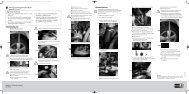
Vor dem Umbau sind folgende Maßnahmen<br />
unbedingt durchzuführen:<br />
Before installation please observe<br />
the following points:<br />
- Lesen Sie die Hinweise auf den folgenden Seiten<br />
aufmerksam durch.<br />
Alle Fahrwerkselemente werden gemäß den<br />
Vorgaben und Richtlinien der Fahrzeughersteller<br />
aus- und eingebaut, sofern in unserer<br />
Einbauanleitung keine davon abweichenden<br />
Maßnahmen beschrieben werden.<br />
- Kontrollieren Sie ob das vorliegende Kit/<br />
Gutachten für Ihren Fahrzeugtyp richtig<br />
ausgewählt ist.<br />
- Kontrollieren Sie vor Beginn der Umbauarbeiten<br />
das Produkt auf Vollständigkeit!<br />
- Vergleichen Sie die Maße und Befestigungspunkte/<br />
-hilfen der Original- Stoßdämpfer mit den<br />
BILSTEIN – Stoßdämpfern.<br />
Read all information in this manual carefully.<br />
All suspension components are fitted and<br />
removed acc. to the manufacturer’s<br />
specifications for fitting and removing, if not<br />
otherwise required in these instructions.<br />
Check that your vehicle type is listed in the<br />
certificate as being specified for this kit.<br />
Check the product for all components before -<br />
starting installation!<br />
Check that dimensions and fastening points are -<br />
comparable between the original and <strong>Bilstein</strong><br />
shock absorbers.<br />
- Entfernen Sie den negativen Batteriepol. Remove the negative battery pole. -<br />
- Richtungsangaben erfolgen immer in Fahrtrichtung<br />
gesehen.<br />
always with reference to the driving direction.<br />
Directional references (left, right, front, rear) are -<br />
- Die Prüffahrzeuge sind Linkslenker. The test vehicles are left- hand drive vehicles. -<br />
-<br />
-<br />
Nach dem Umbau sind folgende Maßnahmen<br />
unbedingt durchzuführen:<br />
After installation please observe<br />
the following points:<br />
- Die Fahrzeughöhe muss mit Hilfe von Federteller<br />
und Kontermutter auf die Stoßdämpfer abgestimmt<br />
werden. Verwenden Sie nur die mitgelieferten<br />
Hakenschlüssel.<br />
- Spur, Sturz und, falls notwendig, die Bremskraftregelung<br />
( lastabhängig) und ABS- Sensoren<br />
sind gemäß Werksangaben zu kontrollieren und<br />
anschließend einzustellen.<br />
- Die Scheinwerfereinstellung ist zu<br />
prüfen und bei Bedarf einzustellen.<br />
- Die Freigängigkeit der Rad-/ Reifenkombination<br />
ist zu überprüfen.<br />
- Federbeine/ Dämpfer die in Gummiaufhängungen<br />
gelagert sind, dürfen erst angezogen werden,<br />
wenn das Fahrzeug wieder auf dem Boden<br />
steht. Andere Befestigungen (z. B. Schellen)<br />
müssen vor dem Herablassen des Fahrzeugs<br />
angezogen werden.<br />
Set the vehicle height by adjusting spring plates<br />
and lock nuts on the new dampers. Only use the<br />
supplied spanner wrenches.<br />
After installing the suspension system, caster -<br />
and camber must be checked and adjusted<br />
according to manufacturer’s specifications.<br />
Check and reset load- dependent brake<br />
compensator and ABS system according<br />
to manufacturer’s specifications.<br />
Check and adjust headlight setting. -<br />
Because the vehicle has been lowered,<br />
freedom of movement for all wheel-/<br />
tire- combinations must be checked.<br />
All rubber- mounted strut/ damper attachments<br />
must not be fully tightened<br />
until AFTER the suspension system is loaded<br />
(wheels on the ground). Other mounting<br />
fasteners (for example brackets)<br />
must be securely tightened BEFORE load<br />
is placed on the suspension system.<br />
- Den negativen Batteriepol wieder anschließen. Connect the negative battery pole. -<br />
Darstellungen in diesen Unterlagen sind schematisch<br />
und nicht maßstabsgetreu!<br />
Möglicherweise sind Halter o. ä. am Federbein<br />
nicht oder nur angedeutet dargestellt!<br />
All diagrams are generalized<br />
and not to scale!<br />
brackets, etc. specific to<br />
strut are not shown!<br />
-<br />
-<br />
-<br />
erstellt am: 15.04.05 E4-WM4-Y563A00_10 Seite 2 von 24 geändert am: 16.05.13
Hinweis für die Kraftverstellung - instruction for force adjustment<br />
Verstellposition 9 = weich ( im Uhrzeigersinn drehen )<br />
Verstellposition 1 = hart ( gegen Uhrzeigersinn drehen )<br />
position 9 = soft ( clockwise direction)<br />
position 1 = firm ( counter- clockwise direction)<br />
Beim Verstellen muss das Einrasten auf den verschiedenen<br />
Positionen mit einem „ Klick“ deutlich spürbar sein.<br />
During the adjustment you will hear a positive<br />
„ click“ at each position of the adjustment.<br />
Hinweis zur Vorderachse<br />
Die Verstelleinheit der Federbeine befindet sich<br />
an der Unterseite, geschützt durch eine blaue<br />
Kunststoffkappe, die zur Verstellung entfernt werden<br />
muss. Nach der Verstellung muss die Kappe wieder<br />
aufgedrückt werden.<br />
Instruction for the front axle<br />
The adjusting element of the front struts is located<br />
at the bottom edge of the strut, covered by a<br />
blue plastic cap. That cap must be removed<br />
before adjusting. After the adjustment the cap<br />
must be replaced again.<br />
Tabelle Anzugsmomente - list of torques<br />
Gewinde M8 M 10 M 12 M 14 M 16 Thread<br />
Anzugsmoment<br />
Nm<br />
13 25 45 72 110<br />
10 19 34 54 83<br />
Torque<br />
Nm<br />
Torque<br />
ft lb<br />
Um eine mögliche Zerstörung des Produktes<br />
zu vermeiden, darf zum Lösen und Anziehen<br />
der Muttern kein Schlagschraubendreher<br />
verwendet werden.<br />
Selbstsichernde Muttern dürfen nur<br />
einmal verwendet werden!<br />
Do not use an impact tool to loosen<br />
or tighten fasteners due to possible<br />
damage to the product.<br />
Self- locking nuts must only be<br />
used once!<br />
erstellt am: 15.04.05 E4-WM4-Y563A00_10 Seite 3 von 24 geändert am: 16.05.13
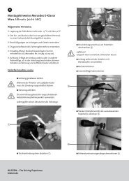
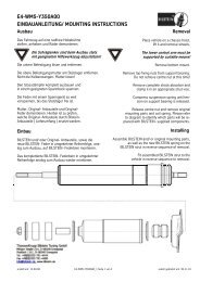
Einbauanleitung für Vorderachse links/ rechts - mounting instruction for front axle left/ right<br />
Ausbau<br />
Das Fahrzeug auf eine radfreie Hebebühne<br />
stellen, anheben und Räder demontieren.<br />
Bei Fahrzeugen mit Xenon- Licht ist vor dem Ausbau<br />
der Federbeine, das bewegliche Element des Sensors<br />
für die Leuchtweitenregulierung zu demontieren.<br />
Die Schräglenker sind beim Ausbau stets<br />
mit geeignetem Hilfswerkzeug abzustützen!<br />
Die untere Befestigung lösen und entfernen.<br />
Die oberen Befestigungsmutter am Stützlager<br />
entfernen. Nicht die Kolbenstangen- Mutter lösen!<br />
Das Federbein komplett ausbauen und in einem<br />
geeigneten Spannbock spannen.<br />
Die Feder mit einem Spanngerät so weit vorspannen,<br />
bis das Stützlager frei ist.<br />
Mutter, Original- Anbauteile und Original- Feder<br />
demontieren. Hierbei ist zu prüfen, welche Original-<br />
Anbauteile durch <strong>Bilstein</strong>- Anbauteile ( Lieferumfang )<br />
ersetzt werden.<br />
Einbau<br />
BILSTEIN und/ oder Original- Anbauteile,<br />
sowie die neue BILSTEIN- Feder in umgekehrter<br />
Reihenfolge, analog zum Ausbau, auf<br />
BILSTEIN- Federbein montieren.<br />
Der im Gutachten angegebene Verstellbereich<br />
der Federteller darf nicht unter- oder<br />
überschritten werden!<br />
Die Einbaulage der Federn ist an der Bedruckung<br />
ablesbar. Die Federbezeichnung muss in Einbaulage<br />
lesbar sein.<br />
Druck- Anschlagpuffer nicht wiederverwenden,<br />
da im BILSTEIN Federbein bereits ein Druck-<br />
Anschlagpuffer eingebaut ist.<br />
Das komplettierte BILSTEIN- Federbein in umgekehrter<br />
Reihenfolge analog zum Ausbau wieder montieren.<br />
Removal<br />
Place vehicle on a wheel-free car hoist,<br />
lift it and remove wheels.<br />
Vehicles equipped with xenon headlight the<br />
movable element of sensor for the headlamp<br />
levelling controller must removed before.<br />
The lower control arm must be<br />
supported by suitable means!<br />
Remove bottom mount.<br />
Remove top fixing nuts from support bearing.<br />
Do not remove central nut at this time!<br />
Remove complete strut and<br />
clamp it in an appropriate strut vice.<br />
Using a suitable spring compressor, compress<br />
suspension spring until tension on support bearing<br />
is free to move.<br />
Release central nut and remove original<br />
mounting parts and coil spring. Please refer<br />
to diagram to identify which parts will be replaced<br />
with BILSTEIN- supplied components.<br />
Installation<br />
Assemble BILSTEIN and/ or original<br />
mounting parts, as well as the new<br />
BILSTEIN spring on the BILSTEIN<br />
strut in reverse order as removal.<br />
IMPORTANT! Spring plates must<br />
not be adjusted outside the<br />
ranges specified in the certificate!<br />
The correct mounting position of the suspension<br />
springs can be determined by the printing on<br />
the springs; install them with the print upright.<br />
Do not reuse original- bumper, since<br />
BILSTEIN- strut has built in bump stop.<br />
Fit assembled BILSTEIN strut to the<br />
vehicle in reverse order as removal.<br />
erstellt am: 15.04.05 E4-WM4-Y563A00_10 Seite 4 von 24 geändert am: 16.05.13
Vorderachse links/ rechts - front axle left/ right<br />
‣<br />
erstellt am: 15.04.05 E4-WM4-Y563A00_10 Seite 5 von 24 geändert am: 16.05.13
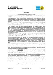
Einbauanleitung für Hinterachse - mounting instruction for rear axle<br />
Ausbau<br />
Removal<br />
Fahrzeug auf eine radfreie Hebebühne stellen,<br />
anheben und Räder demontieren.<br />
Die Schräglenker sind beim Ausbau<br />
stets mit geeignetem Hilfswerkzeug<br />
abzustützen!<br />
Untere und obere Befestigung am<br />
Stützlager entfernen.<br />
Anschließend den Stoßdämpfer ausbauen<br />
und die Original Anbauteile demontieren.<br />
<strong>B16</strong>- 9- fach- Stift- Verstellung<br />
Die Verstelleinheit muss zuerst demontiert werden,<br />
bevor der BILSTEIN Stoßdämpfer mit BILSTEIN und /<br />
oder Original- Anbauteilen, in umgekehrter Reihenfolge,<br />
analog zum Ausbau komplettiert werden kann.<br />
Place vehicle on a wheel-free car hoist,<br />
lift it and remove wheels.<br />
The lower control arm must be<br />
supported by suitable means!<br />
Remove top and bottom fixing<br />
mount from support bearing.<br />
Remove shock absorber and<br />
original mounting parts.<br />
<strong>B16</strong>- 9 step- pin adjustment<br />
The adjustment unit must be deinstall before<br />
the shock absorber installation can be completed<br />
in reverse order with BILSTEIN and/ or<br />
original mounting parts.<br />
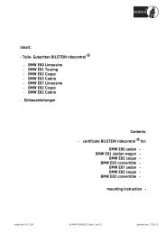
A- Verstellscheibe<br />
adjusting knob<br />
B- Gewindestift<br />
set screw<br />
C- Verstellkopf<br />
adjusting head<br />
D- Kontermutter M12x 1<br />
counter nut<br />
E- Verstellstift<br />
adjusting pin<br />
F- Anschlag mit 4- kant- Zapfen<br />
square rod stop<br />
G- federndes Druckstück m. Kugel Verstellposition 9 = weich ( im Uhrzeigersinn drehen )<br />
spring- loaded detent ball Verstellposition 1 = hart ( gegen Uhrzeigersinn drehen )<br />
position 9 = soft ( clockwise direction)<br />
position 1 = firm ( counter- clockwise direction)<br />
erstellt am: 15.04.05 E4-WM4-Y563A00_10 Seite 6 von 24 geändert am: 16.05.13
erstellt am: 15.04.05 E4-WM4-Y563A00_10 Seite 7 von 24 geändert am: 16.05.13
erstellt am: 15.04.05 E4-WM4-Y563A00_10 Seite 8 von 24 geändert am: 16.05.13
erstellt am: 15.04.05 E4-WM4-Y563A00_10 Seite 9 von 24 geändert am: 16.05.13
erstellt am: 15.04.05 E4-WM4-Y563A00_10 Seite 10 von 24 geändert am: 16.05.13
erstellt am: 15.04.05 E4-WM4-Y563A00_10 Seite 11 von 24 geändert am: 16.05.13
erstellt am: 15.04.05 E4-WM4-Y563A00_10 Seite 12 von 24 geändert am: 16.05.13
erstellt am: 15.04.05 E4-WM4-Y563A00_10 Seite 13 von 24 geändert am: 16.05.13
erstellt am: 15.04.05 E4-WM4-Y563A00_10 Seite 14 von 24 geändert am: 16.05.13
erstellt am: 15.04.05 E4-WM4-Y563A00_10 Seite 15 von 24 geändert am: 16.05.13
erstellt am: 15.04.05 E4-WM4-Y563A00_10 Seite 16 von 24 geändert am: 16.05.13
erstellt am: 15.04.05 E4-WM4-Y563A00_10 Seite 17 von 24 geändert am: 16.05.13
ThyssenKrupp <strong>Bilstein</strong> GmbH<br />
Milsper Straße 214; D-58256 Ennepetal<br />
Postfach 1151, D-58240 Ennepetal<br />
Phone: +49 2333 791-4444<br />
Fax: +49 2333 791-4400<br />
info@bilstein.de, www.bilstein.de<br />
erstellt am: 15.04.05 E4-WM4-Y563A00_10 Seite 18 von 24 geändert am: 16.05.13
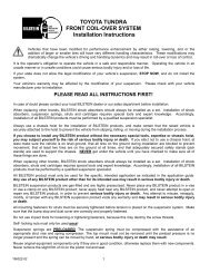
Ausbau <strong>B16</strong><br />
Zuerst die Verstellscheibe ( A) in<br />
Position 9 ( siehe Skizze) bringen.<br />
The adjusting knob ( A) must be<br />
positioned on 9 ( see sketch).<br />
Disassembly <strong>B16</strong><br />
Anschließend den Gewindestift ( B) mit einem<br />
1,5 mm Innensechskantschlüssel lösen, um die<br />
Verstellscheibe abnehmen zu können.<br />
Mit einem geeignetem Werkzeug ( SW 21) den<br />
Verstellkopf ( C) festhalten um die Kontermutter<br />
( D; SW 17) lösen zu können.<br />
Nun können der Verstellkopf und die Kontermutter<br />
zur Montage der Stoßdämpfer entfernt werden.<br />
Die Stoßdämpfer gemäß Einbauanleitung montieren.<br />
Bei nicht fachgerechter Montage der Dämpfer ist die<br />
Verstellfunktion nicht mehr gewährleistet.<br />
Einbau <strong>B16</strong><br />
Den Anschlag ( F) an der Kolbenstange im Uhrzeigersinn<br />
bis zum Endpunkt drehen ( Bypass offen).<br />
Zuerst die Kontermutter, anschließend den Verstellkopf<br />
wieder auf die Kolbenstange aufschrauben. Die Oberseite<br />
des Verstellkopfes darf nicht tiefer als bis zur Unterkante<br />
des 4- kant- Zapfens aufgeschraubt werden<br />
( Maß L ~ 0 bis 1 mm).<br />
Die Kerbmarkierung ( H) am Verstellkopf muss dabei<br />
in der Mitte einer der Schlüsselflächen des 4-kant-<br />
Zapfens stehen. Anschließend kann der Verstellkopf<br />
mit der Kontermutter gesichert werden.<br />
Dann muss Verstellscheibe plan auf den Verstellkopf<br />
auf gelegt werden, was bedeutet, dass das federnde<br />
Druckstück ( G) eine geringe Vorspannung erhält.<br />
Dadurch wird gewährleistet, dass die Kugel des Druckstücks<br />
beim Verstellvorgang in die auf der Unterseite der<br />
Verstellscheibe angebrachten Ausnehmungen spürbar<br />
und mit einem deutlichen „Klick“ einrasten kann.<br />
Die Position 9 auf der Verstellscheibe muss sich direkt<br />
über der am Verstellkopf angebrachten Kerbmarkierung<br />
befinden. In dieser Position kann dann der Gewindestift<br />
wieder angezogen werden.<br />
Die Verstellscheibe muss sich anschließend<br />
leicht drehen lassen.<br />
Loosen the set screw ( B) by an 1,5 mm hex<br />
key and remove the adjusting plate.<br />
Hold the adjusting head ( C) with<br />
an appropriate tool ( SW 21 spanner),<br />
and loosen the lock nut ( D; SW 17).<br />
Now the adjusting head and lock nut can be<br />
removed, to install the shock absorber.<br />
The installation of the shock absorbers must be<br />
done according to the mounting instructions.<br />
Improper installation will render the<br />
adjustment function inoperative!!<br />
Assembly <strong>B16</strong><br />
The square rod stop ( F) must be turned in<br />
clockwise direction fully to its stop ( soft).<br />
Assemble first the lock nut, then the adjusting head. Do<br />
not thread the top of the adjusting head ( C)<br />
past the stop at the bottom edge of the square<br />
section ( F). A gap ( L) of 0 to 1 mm is necessary!<br />
H<br />
C<br />
Orient the score mark ( H) on adjusting head<br />
in the centre of any of the four<br />
sides of the square rod stop. Then lock the<br />
parts together by screwing the lock nut up<br />
to the adjuster head.<br />
The adjusting knob ( A) must be placed flat on the<br />
adjusting head, so that the spring-loaded detent ball<br />
( G) is slightly preloaded. During adjustment the<br />
ball must snap with a positive „click“ into the<br />
notches on the lower side of the knob.<br />
Position 9 must be positioned directly above the<br />
score mark on the adjusting head ( C).<br />
Then tighten the set screw ( B).<br />
The adjusting knob ( A) should move easily and with<br />
distinct „clicks“ at each adjustment position. If not, disassemble<br />
the adjuster mechanism and reassemble according<br />
to the instructions<br />
erstellt am: 15.04.05 E4-WM4-Y563A00_10 Seite 19 von 24 geändert am: 16.05.13
Einbau<br />
BILSTEIN und/ oder Original- Anbauteile, sowie<br />
die neue BILSTEIN- Feder in umgekehrter<br />
Reihenfolge, analog zum Ausbau,<br />
auf BILSTEIN- Stossdämpfer montieren.<br />
Der im Gutachten angegebene Verstellbereich<br />
der Federteller darf nicht unteroder<br />
überschritten werden!<br />
Den komplettierten Stossdämpfer in umgekehrter<br />
Reihenfolge analog zum Ausbau wieder montieren.<br />
Die Einbaulage der Federn ist an der<br />
Bedruckung ablesbar. Die Federbezeichnung<br />
muss in Einbaulage lesbar sein.<br />
Installing<br />
Assemble BILSTEIN and/ or original mounting<br />
parts, as well as the new BILSTEIN spring<br />
on BILSTEIN shock absorber in<br />
reverse order as removal.<br />
IMPORTANT! Spring plates must<br />
not be adjusted outside the<br />
ranges specified in the certificate!<br />
Fit assembled shock absorber to the<br />
vehicle in reverse order as removal.<br />
The correct mounting position of the suspension<br />
springs can be determined by the printing on<br />
the springs; install them with the print upright.<br />
1 2<br />
erstellt am: 15.04.05 E4-WM4-Y563A00_10 Seite 20 von 24 geändert am: 16.05.13
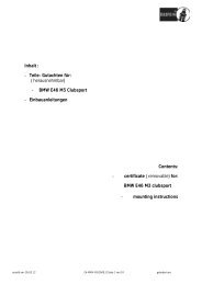
ø45mm<br />
100mm<br />
Hinterachse - rear axle<br />
OE=<br />
erstellt am: 15.04.05 E4-WM4-Y563A00_10 Seite 21 von 24 geändert am: 16.05.13
Hinterachs- Höhenverstellung - adjustment assembly rear axle<br />
erstellt am: 15.04.05 E4-WM4-Y563A00_10 Seite 22 von 24 geändert am: 16.05.13
erstellt am: 15.04.05 E4-WM4-Y563A00_10 Seite 23 von 24 geändert am: 16.05.13
ThyssenKrupp <strong>Bilstein</strong> GmbH<br />
Milsper Straße 214; D-58256 Ennepetal<br />
Postfach 1151, D-58240 Ennepetal<br />
Phone: +49 2333 791-4444<br />
Fax: +49 2333 791-4400<br />
info@bilstein.de, www.bilstein.de<br />
erstellt am: 15.04.05 E4-WM4-Y563A00_10 Seite 24 von 24 geändert am: 16.05.13