Einbauanleitung_VA_W164_E4-WM5-Y368A00.qxd ... - Bilstein
Einbauanleitung_VA_W164_E4-WM5-Y368A00.qxd ... - Bilstein
Einbauanleitung_VA_W164_E4-WM5-Y368A00.qxd ... - Bilstein

Create successful ePaper yourself
Turn your PDF publications into a flip-book with our unique Google optimized e-Paper software.
<strong>Einbauanleitung</strong>_<strong>VA</strong>_<strong>W164</strong>_<strong>E4</strong>-<strong>WM5</strong>-<strong>Y368A00.qxd</strong>:<strong>Einbauanleitung</strong>_hinten 21.06.2010 15:59 Uhr Seite 1<br />
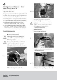
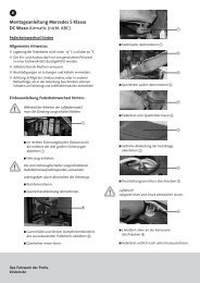
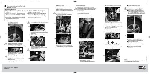
D Montageanleitung Mercedes ML/GL<br />
W/X164 Airmatic<br />
Allgemeine Hinweise:<br />
■ Lagerung der Federbeine nicht unter -15 °C und<br />
über 50°C.<br />
■ Der Ein- und Ausbau darf nur von geschultem<br />
Personal in einer Fachwerkstatt durchgeführt<br />
werden.<br />
■ Zum Umbau ist Werkzeug und Ausrüstung des<br />
Fahrzeugherstellers erforderlich!<br />
■ Leitungen und Kabel auf Beschädigungen<br />
überprüfen und ggf. ersetzen.<br />
■ Achtung: Erfolgt der Umbau anders, oder in<br />
anderer Reihenfolge, als in der Anleitung<br />
beschrieben, können Schäden an Fahrzeug<br />
und Luftfedermodul entstehen!<br />
!<br />
■ Kabelbinder trennen.<br />
■ Bremsschlauch aus Fixierung lösen.<br />
■ Querlenker unten lösen.<br />
■ Koppelstange vom Stoßdämpfer trennen.<br />
■ Spurstange vom Achsschenkel demontieren.<br />
■ Verbindung des oberen Querlenkers trennen.<br />
Geeignete Abzieher verwenden.<br />
■ Untere Befestigungsgabel des Federbeins<br />
demontieren .<br />
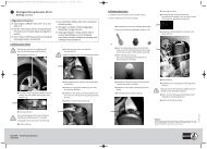
Federbeineinbau vorne<br />
!<br />
Alle beweglichen, fahrwerksrelevanten Schraub -<br />
verbindungen erst im fahrfertigen Zustand vollständig<br />
festziehen, dabei Vorgaben und Anzugsmomente des<br />
Herstellers befolgen.<br />
■ Selbstsichernde Muttern erneuern.<br />
■ Neue Kabelbinder verwenden.<br />
■ Neues Federbein nach oben einsetzen<br />
und die oberen Muttern anlegen .<br />
<br />
■ Spurstange am Achsschenkel montieren .<br />
!<br />
■ Druckleitung anschrauben (5Nm).<br />
■ Sicherung einsetzen.<br />
Fahrzeug niemals mit druckloser Luftfederung<br />
vollständig von der Hebebühne ablassen.<br />
■ Motor starten, Fahrzeug auf ursprüngliches<br />
Fahrzeugniveau ablassen, Anhebefunktion<br />
der Bordelektronik betätigen, und min. zwei<br />
Minuten warten (dabei Fahrzeugtüren schließen).<br />
Federbeinausbau vorne<br />
■ Lenkung geradeaus stellen.<br />
■ Fahrzeughöhe messen .<br />
!<br />
<br />
Luftdruck! Langsam lösen und Luft entweichen lassen.<br />
<br />
<br />
■ Stecker (Dämpferventil) einstecken.<br />
■ ADS-Leitung und Bremsschlauch in jeweiliger<br />
werksseitiger Führung fixieren.<br />
■ Bremsschlauch mit neuem Kabelbinder am<br />
Achsschenkel in ursprüngliche Position bringen.<br />
■ Radhausverkleidung montieren.<br />
<br />
■ Rad montieren.<br />
<br />
■ Leitung während der Arbeiten mit Blindstopfen<br />
verschließen.<br />
■ Drei Muttern am Federbeindom lösen .<br />
■ Schraubanschluss des neuen Luftfedermoduls<br />
abschrauben, dabei nicht vorab<br />
Kunststoffstopfen entfernen!<br />
■ Radhausverkleidung vorne demontieren .<br />
<br />
<br />
<br />
■ Federbeingabel am unteren Querlenker<br />
montieren .<br />
■ Hebebühne erst vollständig ablassen,<br />
wenn sich Fahrzeug selbstständig anhebt.<br />
■ System auf Dichtheit prüfen.<br />
!<br />
<br />
Während der Arbeiten am Luftfedermodul<br />
muss die Zündung ausgeschaltet bleiben.<br />
■ Im rechten Sicherungskasten (Motorraum) die vordere,<br />
der beiden großen Sicherungen (40A) abziehen .<br />
!<br />
■ ADS-Leitung aus Fixierung lösen.<br />
■ Stecker (Dämpferventil) des auszubauenden<br />
Federbeins abziehen .<br />
Zum Entfernen Clip drehen.<br />
■ Unteren Querlenker herunterdrücken und<br />
Federbein seitlich nach unten herausnehmen.<br />
■ Alten Druckleitungsanschluss durch Neuteile<br />
ersetzen. Auf korrekte Montage des Konusrings<br />
achten (Konus zeigt in Richtung<br />
Schraubanschluss) .<br />
■ Beim Umbau gelöste Schraubverbindungen<br />
nach Vorgaben des Herstellers vollständig<br />
festziehen.<br />
■ Anschließend eine Achsvermessung<br />
durchführen.<br />
■ Domstrebe demontieren (nur GL-Modell).<br />
<br />
■ Fahrzeug anheben.<br />
!<br />
Die vom Fahrzeughersteller vorgeschriebenen<br />
Hebebühnenaufnahmepunkte verwenden.<br />
Lebensgefahr durch Abrutschen des Fahrzeugs.<br />
■ Rad demontieren.<br />
■ Druckleitungsanschluss am Federbein<br />
abschrauben .<br />
<br />
■ Oberen Querlenker montieren.<br />
■ Koppelstange am Stoßdämpfer montieren.<br />
<br />
Hinweis:<br />
BILSTEIN übernimmt keinerlei Haftung für Schäden an Fahrzeug und Teilen<br />
bei unsachgemäßem Austausch. Sämtliche Veränderungen an dem<br />
Luftfedermodul führen zum Erlöschen der Garantie!<br />
<strong>E4</strong>-<strong>WM5</strong>-Y368A00<br />
BILSTEIN – The Driving Experience<br />
bilstein.de
<strong>Einbauanleitung</strong>_<strong>VA</strong>_<strong>W164</strong>_<strong>E4</strong>-<strong>WM5</strong>-<strong>Y368A00.qxd</strong>:<strong>Einbauanleitung</strong>_hinten 21.06.2010 15:59 Uhr Seite 4<br />
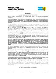
GB<br />
Fitting Information Mercedes ML/GL<br />
W/X164 Airmatic<br />
General information:<br />
■ Do not store struts below -15 °C and above<br />
50°C.<br />
■ Disassembly and installation are only to<br />
be performed by fully qualified and certified<br />
personnel at a specialist garage.<br />
■ Car manufacturer special tools and equipment<br />
is required!<br />
■ Check air pipes and cables – renew if damaged.<br />
■ Caution! Damage to the vehicle and the air<br />
suspension module can occur if work is carried<br />
out in a manner other than that specified in<br />
the instruction or in a different sequence.<br />
!<br />
<br />
■ Disconnect electric plug (shock absorber valve)<br />
of the strut being dismantled .<br />
Turn clip to remove.<br />
■ Open the cable strap.<br />
Installing the front struts<br />
!<br />
Only fully tighten all movable, suspension related<br />
screw connections in ready-to-drive condition<br />
observing the manufacturer’s specifications and<br />
tightening torques.<br />
■ Renew self-locking nuts.<br />
■ Renew cable straps.<br />
■ Fit new strut upwards and position the<br />
upper nuts .<br />
<br />
■ Assemble the steering tie rod .<br />
!<br />
■ Screw on pressure line (5Nm).<br />
■ Insert fuse.<br />
Never completely lower the vehicle from the lifting<br />
platform if the air suspensions are not pressurized.<br />
■ Start the engine. Lower the vehicle up to standard<br />
vehicle height from the lifting platform.<br />
Operate the raising function of the electronics<br />
, and wait for at least 2 minutes (keep the<br />
doors closed during the period).<br />
Dismantling the front struts<br />
<br />
■ Set steering straight ahead.<br />
■ Measure the standard vehicle height .<br />
!<br />
!<br />
<br />
Use a chassis hoist and make certain that the<br />
raised vehicle is securely attached to the hoist to<br />
prevent the vehicle from slipping, falling, or moving<br />
during the installation process.<br />
If you choose to install any BILSTEIN product<br />
without the necessary special tools, expertise or<br />
chassis hoist, you may subject yourself to the risk<br />
of serious bodily injury or death.<br />
■ Remove wheel.<br />
■ Unscrew pressure line connection at the strut .<br />
Air pressure! Loosen slowly and allow air to escape.<br />
!<br />
<br />
■ Take off brake hose from the bracket.<br />
■ Loosen the inner (frame side) fixture of<br />
the bottom control arm.<br />
■ Dismantle stabilizer (link).<br />
■ Remove the steering tie rod.<br />
■ Loosen the support link of the upper track<br />
control arm (spindle side).<br />
Use suitable tools.<br />
■ Remove the bottom strut from the fixing fork .<br />
<br />
■ Assemble strut fork to the bottom track<br />
control arm .<br />
!<br />
■ Insert plug (shock absorber valve) of the<br />
strut being fitted.<br />
■ Lock ADS-cable and brake hose into<br />
designated positions.<br />
■ Secure brake hose with new cable strap<br />
to the steering knuckle.<br />
■ Assemble inner fender.<br />
■ Mount the wheel.<br />
■ Screw off air pipe connection of the new<br />
suspension strut.<br />
Don’t remove plastic plug first.<br />
<br />
<br />
■ Only lower completely when the vehicle<br />
raises of its own accord.<br />
■ Check air suspension system for leaks.<br />
!<br />
The ignition must remain switched off<br />
during the work on the air suspension module.<br />
■ There are two large fuses (40A) in the right fuse box<br />
(under the hood), remove the front fuse only .<br />
■ Seal off line with plugs.<br />
■ Dismantle the front part of the inner fender .<br />
■ Remove the 3 nuts on the strut dome .<br />
■ Replace used parts of air pipe connection by<br />
the new parts. Pay attention to the correct<br />
position of the tapered ring (the cone must<br />
go with the screw connector) .<br />
■ Fully tighten screws loosed during the work<br />
in ready-to-drive-condition in accordance<br />
with the manufacturer’s specifications.<br />
■ A following front end alignment is required.<br />
<br />
<br />
<br />
<br />
■ Dismantle front strut brace (only<br />
GL-models).<br />
■ Raise vehicle.<br />
■ Take off ADS-cable from the bracket.<br />
■ Push the bottom track control arm down and<br />
remove the strut sideways and downwards.<br />
■ Assemble support link of the upper track<br />
control arm.<br />
■ Assemble stabilizer (link).<br />
<br />
Note:<br />
Manufacturer shall not be liable for any injury, loss or damage resulting<br />
from any improper alteration, disassembly, handling, installation, service,<br />
repair or use of this product, including but not limited to the failure to follow<br />
the foregoing instructions.<br />
Improper alteration, disassembly, handling, installation, service, repair or use<br />
of this product will void the product warranty.<br />
<strong>E4</strong>-<strong>WM5</strong>-Y368A00<br />
Engineered for performance.<br />
bilstein.de