Katalog - Rehsler Kühlsysteme
Katalog - Rehsler Kühlsysteme
Katalog - Rehsler Kühlsysteme

Erfolgreiche ePaper selbst erstellen
Machen Sie aus Ihren PDF Publikationen ein blätterbares Flipbook mit unserer einzigartigen Google optimierten e-Paper Software.
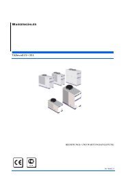
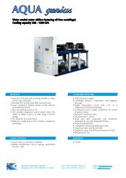
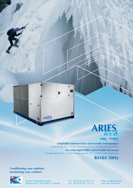
Luftgekühlte Kaltwassersätze und reversible Wärmepumpen<br />
(Kälteleistung 162 - 331 kW, Wärmeleistung 179 - 374 kW, Scroll-Verdichter)<br />
Air-cooled liquid chillers and reversible heat pumps<br />
(Cooling capacity 162 - 331 kW, heating capacity 179 - 374 kW, scroll compressors)<br />
R410A 50Hz<br />
Conditioning your ambient,<br />
maximising your comfort.<br />
<strong>Rehsler</strong> Kühlsysteme GmbH Tel.: +49 (0) 83 82 / 96 23 -0 eMail: info@rehsler.de<br />
Bregenzer Str. 130, D-88131 Lindau/B. Fax: +49 (0) 83 82 / 7 91 12 web: www.rehsler.de
Technische vorschriften<br />
Technical specifications<br />
Leitfaden zur Auswahl<br />
Selection guide<br />
Leistungen und technische Daten<br />
Performance and technical data<br />
Verluste der Verdampfer<br />
Pressure drops and available head pressure<br />
Betriebsgrenzen, Korrekturkoeffizienten<br />
Working limits, Correction coefficients<br />
Verflüssiger und Rückgewinnungsenthitzer (Sonderausführungen)<br />
Recovery condenser and desuperheaters (optionals)<br />
Gesamtzeichnungen<br />
Overall dimensions<br />
Installationsanleitung<br />
Installation guide<br />
2<br />
11<br />
14<br />
30<br />
31<br />
32<br />
34<br />
37<br />
Inhaltsverzeichnis - Index
TECHNISCHE SPEZIFIKATIONEN - TECHNICAL SPECIFICATIONS<br />
1 Allgemeines<br />
2 Sonorisierte Konfigurationen und Versionen<br />
3 Abkürzung<br />
4 Abnahme<br />
5 Verdichter<br />
6 Verdampfer<br />
7 Verflüssigerregister<br />
8 Verflüssiger und Rückgewinnungsenthitzer<br />
(Sonderausführungen)<br />
9 Elektroventilatoren<br />
10 Kältekreislauf<br />
11 Integriertes Hydronic-Modul (optional)<br />
12 Aufbau und Gehäuse<br />
13 Schaltschrank<br />
14 Steuerung<br />
15 Optionen, Kits und Sonderausführungen<br />
1. Allgemeines<br />
Die Kaltwassersätze und reversiblen Wärmepumpen der Serie Aries tech sind<br />
Einheiten, die für die Anwendung im Freien entwickelt wurden (Schutzgrad<br />
IP54), mit einem Verflüssiger mit Lamellenpaket luftgekühlt werden, mit<br />
Axialventilatoren, 4 hermetischen Scroll-Verdichtern, von denen immer<br />
jeweils zwei parallel in einem doppelten Kältekreis angeschlossen<br />
sind, mit unabhängigen aeraulischen Verflüssigerabschnitten und einem<br />
einzelnen Plattenverdampfer mit doppeltem Gaskreis. Sie sind für die<br />
Integration des Pumpenmoduls mit oder ohne Speichertank vorgesehen.<br />
Diese Lösungen ermöglichen die Verbesserung der Energieeffizienzwerte<br />
bei niedrigen Lasten, die den Hauptanteil im Laufe des Betriebslebens<br />
einer Einheit darstellen, die für die Klimatisierung bestimmt ist, wobei die<br />
jahreszeitlichen Leistungszahlen ESEER (*) und IPLV (*) optimiert werden.<br />
Die Verwaltung ist einer Mikroprozessorsteuerung anvertraut, die<br />
vollkommen selbständig alle Hauptfunktionen wie Einstellungen, Alarme<br />
und Schnittstelle mit den externen Geräten verwaltet. Das verwendete<br />
Kältemittel ist R410A. Alle Einheiten wurden mit Komponenten von<br />
Markenherstellern entsprechend den Normen ISO 9001 geplant, hergestellt<br />
und kontrolliert.<br />
1 General<br />
2 Acoustic configurations and versions<br />
3 Nameplate<br />
4 Testing<br />
5 Compressors<br />
6 Evaporator<br />
7 Condensing coils<br />
8 Recovery condenser and desuperheaters<br />
(optionals)<br />
9 Fans<br />
10 Refrigerant circuit<br />
11 Integrated hydronic module (optional)<br />
12 Structure and casing<br />
13 Electrical Panel<br />
14 Control<br />
15 Options, kits and special designs<br />
1. General<br />
The chillers and reversible heat pumps in the Aries tech series are<br />
designed for outdoor installation ( IP54 protection rating). These<br />
units are air-cooled, equipped with a finned core condenser, axial<br />
fans, 4 hermetic scroll compressors connected in parallel pairs<br />
in a dual refrigerant circuit, independent aeraulic condensing<br />
sections, and single plate type dual gas circuit evaporator. The<br />
units are prearranged to accommodate a pumping module with<br />
or without a water storage tank. These solutions make it possible<br />
to enhance energy efficiency at low loads, which account for the<br />
largest proportion of the working life of an air conditioning unit,<br />
thereby maximising ESEER (*) and IPLV (*) seasonal performance<br />
indices.<br />
The units are equipped with a microprocessor controller that offers<br />
fully independent management of all the main functions, including<br />
adjustments, alarms and interface with the periphery. The refrigerant<br />
fluid utilised is R410A.<br />
All units are designed, built and checked in compliance with ISO 9001<br />
and incorporate components sourced from premium manufacturers.<br />
ARIES tech<br />
Das Standard-Produkt, das für die CEE- und EFTA-Staaten bestimmt ist,<br />
unterliegt folgenden Richtlinien:<br />
• Richtlinie über die Elektromagnetische Verträglichkeit 89/336 und<br />
nachfolgenden Änderungen;<br />
• EG-Maschinenrichtlinie 98/37;<br />
• EG-Niederspannungsrichtlinie 2006/95;<br />
• Druckeinrichtungen 97/23/EG.<br />
Der Schaltschrank wurde entsprechend der Normen EN 60204-1 realisiert.<br />
Alle in diesem <strong>Katalog</strong> angegebenen Daten beziehen sich auf<br />
serienmäßige Einheiten in Nennbetriebsbedingungen (es sei denn, es<br />
liegen andere Angaben vor).<br />
(*) Die jahreszeitlichen Leistungszahlen ESEER (European Seasonal<br />
Energy Efficiency Ratio), der im Zusammenhang des europäischen<br />
Projektes geboten und verwendet wird, und IPLV (Integrated Part Load<br />
Value), der vom amerikanischen Standard ARI geboten wird, zeichnen die<br />
durchschnittliche Dauereffizienz eines für die Klimatisierung bestimmten<br />
Kühlers aus. Diese drücken das Verhältnis zwischen Nutzeffekt (den<br />
Räumen entzogene Energie) und Energiekosten (verbrauchte elektrische<br />
Energie) eines Kaltwassererzeugers im Laufe der gesamten Betriebssaison<br />
viel besser als der EER-Wert aus. Der Wert wird in Abhängigkeit von den<br />
verschiedenen Betriebsbedingungen und der Häufigkeit berechnet, mit<br />
der diese erreicht sind; den entsprechenden Leistungen der Einheit wird<br />
eine unterschiedliche Energiegewichtung zugeteilt.<br />
ESEER = 4,3 bedeutet zum Beispiel, dass im Laufe einer ganzen<br />
Betriebssaison für alle 4,3 kWh Wärme, die den zu kühlenden Räumen<br />
entzogen ist, durchschnittlich 1 kWh elektrische Energie verbraucht<br />
wird.<br />
The standard product, destined for EU and EFTA countries, is subject<br />
to the following directives:<br />
• Electromagnetic Compatibility Directive 89/336 and subsequent<br />
amendments;<br />
• Machinery Directive 98/37/EC;<br />
• Low Voltage Directive 2006/95/EC;<br />
• Pressure Equipment Directive 97/23/EC.<br />
The electrical cabinet is constructed in compliance with EN 60204-1.<br />
All data in this catalogue refer to standard units and nominal operating<br />
conditions (unless otherwise specified).<br />
(*) The ESEER (European Seasonal Energy Efficiency Ratio) index<br />
proposed and used in the European design context, and the<br />
IPLV (Integrated Part Load Value) index proposed by the US ARI<br />
standard, characterize the average weighted efficiency of a chiller<br />
for air conditioning applications. Both indices express, far more<br />
accurately than EER, the ratio between the useful effect (energy<br />
removed from interior spaces) and energy expenditure (electrical<br />
energy consumed) of a chiller during an entire season of operation.<br />
In relation to the various different operating conditions and the<br />
frequency with which they occur, these indicators are calculated<br />
by assigning a different energy weight to the corresponding output<br />
values of the unit.<br />
For example ESEER = 4,3 means that during an entire season of<br />
operation 1 kWh of electrical power is required on average to remove<br />
4,3 kWh of heat energy from the air conditioned rooms.<br />
2
Betriebszeitprozentwerte nach ESEER und IPLV<br />
ESEER and IPLV operating time percentages<br />
Energiegewichtungen gemäß den ESEER- und IPLV-Werten<br />
ESEER and IPLV energy weights<br />
42%<br />
37%<br />
46%<br />
ESEER<br />
IPLV<br />
41% 45% 33%<br />
42%<br />
ESEER<br />
IPLV<br />
25%<br />
20%<br />
29%<br />
23%<br />
12%<br />
1.4% 1,4% 0,5%<br />
3,0%<br />
1,0%<br />
25% 50% 75% 100%<br />
Wärmelast Thermal load percentage<br />
2. Sonorisierte Konfigurationen und Versionen<br />
Die ganze Serie Aries tech ist in drei sonorisierten Konfigurationen<br />
erhältlich:<br />
“N” - Sonorisierte Basiskonfiguration: Die Verdichter sind in einem<br />
Metallgehäuse, das teilweise mit schallschluckendem offenzelligen<br />
Schaumgummi sonorisiert ist, verschlossen; Ventilatoren, ca. 900 U/<br />
Min.<br />
“SN” - Sonorisierte leise Konfiguration: Die Verdichter sind in<br />
einem Metallgehäuse, das mit schallschluckendem, offenzelligen<br />
Schaumgummi isoliert ist, verschlossen; Ventilatoren mit reduzierter<br />
Drehung gegenüber der Konfiguration "N", ca. 700 U/Min.<br />
“SSN” - Sonorisierte sehr leise Konfiguration, die für einen<br />
besonders leisen Betrieb optimiert wurde: Die Verdichter sind in<br />
einem Metallgehäuse, das mit schallschluckendem, offenzelligen<br />
Schaumgummi und Geräusch hindernder Folie isoliert ist, verschlossen;<br />
Ventilatoren mit kleineren Dimensionen und reduzierter Drehung<br />
gegenüber der Konfiguration "N", ca. 700 U/Min.<br />
erhöhter Verflüssigerbereich.<br />
25% 50% 75% 100%<br />
Wärmelast Thermal load percentage<br />
2. Acoustic configurations and versions<br />
All units in the Aries tech series are available in three acoustic<br />
configurations:<br />
“N” - Basic acoustic configuration: compressors housed in a metal<br />
compartment partially insulated with a sound absorbing layer of<br />
flexible open-cell expanded polyurethane; fan speed of approx. 900<br />
rpm.<br />
“SN” - Low noise acoustic configuration: compressors housed<br />
in a metal compartment insulated with a sound absorbing<br />
layer of flexible open-cell expanded polyurethane; fans with<br />
reduced speed with respect to the “N” configuration: approx.<br />
700 rpm.<br />
“SSN” - Super Silent acoustic configuration optimised for very<br />
low noise operation: compressors housed in a metal compartment<br />
insulated with a sheet of sound deadening material and layer of<br />
flexible open-cell expanded polyurethane; fans with reduced size<br />
and rotation speed compared to configuration “N”: approx. 700<br />
rpm; oversized condensing section.<br />
„Ausführung mit Verflüssiger zur Gesamtrückgewinnung: 100%<br />
der Gesamtverflüssigungswärme” (siehe Kapitel “Verflüssiger und<br />
Rückgewinnungsenthitzer”).<br />
„Ausführung mit Rückgewinnungsenthitzern: 20% der<br />
Gesamtverflüssigungswärme” (siehe Kapitel “Verflüssiger und<br />
Rückgewinnungsenthitzer”).<br />
Für die Kalt-Modelle sind außerdem die folgenden Versionen erhältlich:<br />
“H” - Version für eine hohe Außentemperatur: Die Verdichter sind<br />
in einem Metallgehäuse, das teilweise mit schallschluckendem<br />
offenzelligen Schaumgummi sonorisiert ist, verschlossen; Ventilatoren,<br />
ca. 900 U/Min.; erhöhter Verflüssigerbereich.<br />
“Version für eine niedrige Außenlufttemperatur” - (bis -20 °C):<br />
Gegenüber den im vorliegenden <strong>Katalog</strong> beschriebenen Einheiten werden<br />
für diese Version elektronische Thermostatventile, Carterwiderstände<br />
der Verdichter, ein belüftetes Heizelement, das durch ein Thermostat<br />
im Schaltschrank gesteuert wird, und Ventilatoren mit kontinuierlicher<br />
elektronischer Regelung, mit Phasenschnitt, für die Regelung des<br />
Verflüssigungsdrucks verwendet. Nicht als H-Version erhältlich.<br />
3. Abkürzung<br />
Jeder Kaltwassersatz kann an seiner Kurzbezeichnung erkannt werden:<br />
“Version with total recovery condenser: 100% of total<br />
rejection heat (see Chapter “Recovery condenser and<br />
desuperheaters”).<br />
“Version with recovery desuperheaters: 20% of total rejection<br />
heat (see Chapter “Recovery condenser and desuperheaters”).<br />
In addition, the following versions are available for cooling-only models:<br />
“H” – Version for high ambient air temperatures: compressors housed<br />
in a metal compartment partially insulated with a sound absorbing<br />
layer of flexible open-cell expanded polyurethane; fan speed of<br />
approx. 900 rpm; oversized condensing section.<br />
“Low ambient temperature version” - (up to –20 °C ): compared to<br />
the other units described in this catalogue, this version is equipped<br />
with electronic thermostatic valves, compressor crankcase heaters, a<br />
ventilated heating element controlled by a thermostat in the electrical<br />
cabinet, and fans with continuous phase cut-off electronic speed<br />
control for the control of condensing pressure. Not available for "H"<br />
version.<br />
3. Nameplate<br />
Every chiller can be identified by its nameplate:<br />
ARIES tech<br />
AST/HAST XXX ZZZ<br />
Version der Einheit "N", "SN", "SSN", "H";<br />
Nennleistung der Verdichter in HP;<br />
AST/HAST XXX ZZZ<br />
Unit version "N", "SN", "SSN", "H";<br />
Nominal power of the compressors, in HP;<br />
ARIES tech / HARIES tech<br />
ARIES tech / HARIES tech.<br />
3
4. Abnahme<br />
Jede hergestellte Einheit wird in einer Prüfkabine abgenommen.<br />
Der korrekte Betrieb wird sowohl unter den üblichsten als auch den<br />
schwersten Betriebsbedingungen geprüft. Insbesondere:<br />
• werden die korrekte Montage aller Komponenten und die<br />
Kältemitteldichtheit überprüft;<br />
• werden elektrische, von der Norm EN60335-2-40 vorgeschriebene<br />
Sicherheitstests ausgeführt;<br />
• wird der korrekte Betrieb der Mikroprozessorsteuerung und der Wert<br />
aller Betriebsparameter überprüft;<br />
• werden die Temperatursonden und die Druckmesswertgeber überprüft;<br />
• Beim Standardbetrieb erfolgt: die Einstellung des Thermostatventils,<br />
die korrekte Kältemittelfüllung, die Verdampfungs- und die<br />
Verflüssigungstemperaturen, die Überhitzung und die Unterkühlung<br />
sowie die gelieferte Kälteleistung.<br />
• Die Abnahme der Wärmepumpen erfolgt sowohl in Kühlungs- als<br />
auch in Heizungsmodalität.<br />
Um eine hohe Zuverlässigkeit der Einheiten zu gewährleisten, sind bei<br />
der Installation der Einheiten nur die elektrischen und hydraulischen<br />
Anschlüsse auszuführen.<br />
5. Verdichter<br />
4. Testing<br />
Each unit is tested in a test chamber in order to check correct operation<br />
both in the most representative operating conditions and in the most<br />
demanding conditions. The following aspects are checked in particular:<br />
• correct installation of all components and possible refrigerant<br />
leaks;<br />
• electrical safety tests performed as prescribed by EN60335-2-40;<br />
• correct operation of the microprocessor controller together with the<br />
value of all operating parameters;<br />
• temperature probes and pressure transducers;<br />
• operation is forced at nominal conditions in order to check:<br />
thermostatic valve calibration, refrigerant charge, evaporation and<br />
condensing temperatures, superheating and subcooling and cooling<br />
duty values;<br />
• heat pumps are tested in both cooling and heating mode.<br />
At the time of installation the units require exclusively electrical and<br />
hydraulic connection, thus ensuring a high level of reliability.<br />
5. Compressors<br />
ARIES tech<br />
4<br />
Die in allen Einheiten der Serie Aries tech verwendeten 4 Scroll-<br />
Verdichter sind hermetisch und immer jeweils zu zweit parallel in<br />
einem doppelten Kältekreis angeschlossen, um das Erreichen der<br />
Leistungsindexe bei Teilbelastungen zu ermöglichen, die den Hauptwert<br />
während der Lebensdauer einer Klimatisiereinheit darstellen. Diese<br />
Lösung ermöglicht außerdem durch die „Unloading-Funktion“ die<br />
Inbetriebnahme der Anlage sowie den Betrieb der Einheit auch in ganz<br />
anderen als den Nennbedingungen.<br />
Die Verdichter der Wärmepumpenausführungen sind mit Carter-<br />
Heizwiderständen ausgestattet; nur die Wärmepumpen werden vor der<br />
Gefahr hoher Temperaturen der Abgase über ein Sicherheitsthermostat<br />
geschützt, das sich am Zulaufrohr jedes Verdichterpaars befindet.<br />
Die verwendeten hermetischen Verdichter weisen zahlreiche Vorteile auf<br />
wie: Reduzierte Druckverluste in der Ansaugung durch die Abwesenheit<br />
von Ventilen, hoher Widerstand gegen eventuelle Flüssigkeitsstöße,<br />
hohe Verdichtungsleistung, hohe Lebenserwartung ohne Wartung, sehr<br />
niedrige Vibrationen und Schalldruckpegel. Jeder Verdichter ist mit einem<br />
Rückschlagventil am Zulauf ausgestattet, das eventuelle Rückströmungen<br />
der Flüssigkeit verhindert. Die Anwesenheit einer entsprechenden<br />
Kontrollleuchte ermöglicht die Ölstandkontrolle im Gehäuse.<br />
Die Wicklungen des Elektromotors sind 2-polig und durch eine<br />
interne Schutzvorrichtung gegen Überlastungen vor Übertemperaturen<br />
geschützt, die ggf. durch einen unnormalen Betrieb entstehen. In den<br />
Verdichtern des Modells 080 ist dieser Schutz durch ein elektronisches<br />
Schutzmodul gewährleistet, das auch die Folge und die Anwesenheit<br />
der Phasen kontrolliert, um entsprechend die umgekehrte Umschaltung<br />
der Verdichter sowie die Überhitzung der Wicklungen, die durch<br />
das Unterbrechen des Laufs einer Phase ausgelöst werden kann, zu<br />
verhindern.<br />
Die Verdichter jedes Kältekreislaufs sind durch ein Längsträgerpaar<br />
aus Metall gebunden, das Aggregat wurde in einer Box, deren<br />
Seitenwände zum vollständigen Zugang entfernt werden können, auf<br />
Gummischwingungsdämpfer montiert.<br />
6. Verdampfer<br />
Der Plattenverdampfer ist aus mit Kupfer gelötetem Edelstahl, mit<br />
doppeltem Gaskreis und einzelnem Wasserkreis. Diese sehr effizienten<br />
und kompakten Wärmetauscher erfordern sehr wenig Platz in der Einheit,<br />
was zum Vorteil der Zugänglichkeit ist. Besonders die Lösung mit zwei<br />
Gaskreisläufen ermöglicht die Erhöhung der Leistungskoeffizienten mit<br />
Teillasten gegenüber den Lösungen mit unabhängigen Verdampfern.<br />
Im oberen Teil des Verdampfers befindet sich immer ein manuelles<br />
Entlüftungsventil und im unteren Teil ein Drainagehahn; er ist<br />
außen mit einer vor Kondensation schützenden Thermoisolierung<br />
aus Schaumelastomeren mit geschlossenen Zellen isoliert<br />
und ist vor Frostgefahr geschützt, was durch eventuelle niedrige<br />
All Aries tech series units are equipped with 4 hermetic scroll<br />
compressors always connected in parallel pairs in a dual refrigerant<br />
circuit to make it possible to achieve superior COP levels at partial<br />
loads, which account for the largest portion of the working life of<br />
an air conditioning unit. Thanks to the “unloading” function, this<br />
solution allows system start-up and operation of the unit also in<br />
conditions that are significantly different from nominal ones.<br />
The compressors of heat pump versions are equipped with crankcase<br />
heaters and are protected from the risk of high temperature gas<br />
discharge by a safety thermostat installed on the discharge line of<br />
each pair of compressors.<br />
The hermetic compressors employed offer a series of benefits,<br />
including: reduced pressure drops on the suction side thanks to the<br />
absence of valves, significant resistance to possible liquid pressure<br />
shocks, high compression efficiency, long working life with zero<br />
maintenance requirements, and very low levels of vibration and<br />
noise emissions. Each compressor is equipped with a check valve<br />
on the discharge line that prevents possible liquid reverse flows. The<br />
presence of the specs oil sight glasses serves to check the oil level<br />
in the crankcases.<br />
The motor windings are of the 2-pole type and are protected against<br />
overheating caused by possible malfunctions by means of an internal<br />
overload protection device. On the compressors of the 080 size unit<br />
this protection is assured by an electronic protection module that<br />
also monitors phase sequence and presence to avoid, respectively,<br />
reverse rotation of compressors and overheating of windings<br />
potentially caused by interruption of a phase while running.<br />
The compressors of each refrigerant circuit are rigidly connected<br />
by a pair of steel rails and the resulting assembly is subsequently<br />
installed on rubber anti-vibration mounts inside an enclosure with<br />
removable lateral panels to allow unimpeded access.<br />
6. Evaporator<br />
The evaporator is of the stainless steel plate type brazed with<br />
copper, with double refrigerant circuit and a single water circuit.<br />
These evaporators are highly efficient and compact, occupying only<br />
minimum space inside the unit, with consequent benefits in terms of<br />
internal accessibility. Specifically, the solution with dual refrigerant<br />
circuit evaporators makes it possible to achieve high COP values at<br />
partial loads compared to solutions with independent evaporators.<br />
All evaporators feature a manual air bleed valve located on the top<br />
and a drain valve at the bottom; they are externally insulated with<br />
thermal insulation and anti-condensation cladding in closed cell<br />
elastomer foam, and are protected from the risk of freezing potentially
Verdampfungstemperaturen verursacht wird, und weist auch eine<br />
Frostschutzfunktion des Steuergeräts auf, das die Ausgangstemperatur<br />
des Wassers kontrolliert. Außerdem ist auf jedem Verdampfer ein<br />
Differentialdruckschalter montiert, der ihn bei Mangel des Wasserflusses<br />
schützt. Der Installateur muss einen Filter am Wassereintritt der Einheit<br />
einsetzen, um eventuelle Schmutzteilchen abzufangen, der sich im<br />
Speicher oder in den Verdampfern ablagern können.<br />
Alle Verdampfer entsprechen den „EG-Vorschriften“ für Druckgefäße<br />
und können mit Frostschutzlösungen und sonstigen Flüssigkeiten<br />
arbeiten, die mit den Materialien des Wasserkreislaufs kompatibel<br />
sind.<br />
7. Verflüssigerregister<br />
Es handelt sich um 2 hinsichtlich der Lüftung unabhängige Register,<br />
die jeweils einem Kältekreis zugehören, entlang den Maschinenseiten<br />
angebracht sind, ein Lamellenpaket mit wirbeligen Alulamellen,<br />
Kupferkollektoren und -rohre, glatt oder gerippt auf der Gasseite, je nach<br />
den Modellen, sowie Halterungen aus verzinktem Blech aufweisen.<br />
Diese Wärmetauscher wurden nach modernen Planungstechniken<br />
computerunterstützt berechnet, bemessen und konstruiert und ermöglichen<br />
die Verwendung von Ventilatoren mit niedriger Drehzahl, wobei eine<br />
weitere Verbesserung der akustischen Leistungen der Einheit gewährleistet<br />
wird.<br />
Die Verflüssigerregister der Ausführung Wärmepumpe sind mit einem<br />
„Verteilernetz“ ausgestattet, um die Kältekreise korrekt zu speisen. In jeder<br />
dieser Verflüssigerregister ist der untere Bereich, der der empfindlichste<br />
Teil hinsichtlich der Bildung und des Entstehens von Frost ist, mit einem<br />
Paar Rohren ausgestattet, die von heißem Gas gespeist werden; diese<br />
Maßnahme vermeidet im Winterbetrieb die Bildung von Eis entlang der<br />
Unterseite des Austauschers und im Auffangbehälter des Kondenswassers<br />
und begünstigt so die Drainage, verbessert die gesamte Effizienz der<br />
Wärmepumpe sowie das Wohlbehagen in den klimatisierten Räumen.<br />
Das Auffangen des Kondenswassers erfolgt über zwei Abtropfvorrichtungen,<br />
die den ganzen unteren Bereich jedes Registers abdecken und mit<br />
Auslassanschlüssen mit Gummihalter ausgestattet sind, die von unten<br />
erreichbar sind.<br />
8. Verflüssiger und Rückgewinnungsenthitzer<br />
(Sonderausführungen)<br />
Für die Chiller und Wärmepumpen der Serie Aries tech sind Ausführungen<br />
mit Wärmerückgewinnern mit gelöteten Platten erhältlich.<br />
caused by low evaporation temperatures, by the antifreeze function<br />
incorporated in the electronic controller, which monitors the water<br />
outlet temperature. In addition, each evaporator is equipped with a<br />
differential water pressure switch to protect it in conditions in which<br />
the water flow is absent or insufficient. Installers should fit a filter<br />
on the unit inlet to intercept any debris in the water supply that may<br />
otherwise deposit in the tank or in the evaporator.<br />
All the evaporators comply with the "EC" pressure vessels directive<br />
and can handle antifreeze solutions and, in general, all other<br />
liquids that are compatible with the hydraulic circuit construction<br />
materials.<br />
7. Condensing coils<br />
Two condensing coils with complete aeraulic independence, each<br />
connected to a refrigerant circuit, located along the sides of the<br />
unit. The coils are of the finned core type with aluminium swirl fins,<br />
copper headers and tubes, either smooth or finned on the refrigerant<br />
side depending on the model, and galvanized sheet metal shoulders.<br />
These exchangers are calculated, sized and designed utilising the<br />
latest CAD techniques and allow the use of reduced speed fans<br />
ensuring a further improvement in the sound emission performance<br />
of the unit.<br />
In the heat pump version the condensing coils are equipped with a<br />
distributor device to ensure correct supply of the refrigerant circuits.<br />
In both the refrigerant circuits the lower section, which is the more<br />
susceptible to ice formation and inception of icing-up phenomena,<br />
is equipped with a pair of tubes carrying hot gas; in winter operation<br />
this solution prevents the formation of ice at the base of the<br />
exchanger and in the condensate collection tray, facilitating drainage<br />
of condensate and improving the global efficiency of the heat<br />
pump while enhancing environmental comfort levels in the climate<br />
controlled rooms.<br />
Condensate is collected in two trays that cover the entire base of<br />
each coil and are equipped with drain outlets with hose connection<br />
accessible from below the unit.<br />
8. Recovery condenser and desuperheaters<br />
(optionals)<br />
Aries tech chillers and heat pumps are available in the version with<br />
heat recovery exchangers of the brazed plate type.<br />
“Ausführung mit Verflüssiger zur Gesamtrückgewinnung (100% der<br />
Gesamtverflüssigungswärme)“:<br />
Der Benutzer kann kostenlos die gesamte Verflüssigungsenergie<br />
der Einheit zurückgewinnen, indem der Warmgasstrom aus den<br />
Hauptverflüssigern an den Rückgewinnungsverflüssiger (einziger<br />
Verflüssiger mit doppeltem Gaskreis und einem Wasserkreis) über<br />
zwei „potentialfreie Kontakte“ im Schaltschrank geleitet wird.<br />
Der Rückgewinnungswärmetauscher ist extern mit einer<br />
Thermoisolierung aus Schaumelastomeren mit geschlossenen Zellen<br />
isoliert. Die Gewindewasseranschlüsse zeigen immer auf einer<br />
Anschlussplatte nach außen. Falls die Anwendung von Wasser am<br />
Eingang des Rückgewinnungsverflüssigers unter 20 °C vorgesehen ist,<br />
müssen Druckventile eingebaut werden. Der Betrieb im 100%igen<br />
Rückgewinnungsmodus kann nur im Sommerbetrieb in Verbindung<br />
mit der Kaltwassererzeugung im Verdampfer erfolgen.<br />
“Ausführung mit Rückgewinnungsenthitzern zur<br />
Gesamtrückgewinnung (20% der Gesamtverflüssigungswärme)“:<br />
Der Benutzer kann kostenlos etwa 20% der ganzen Verflüssigungsenergie<br />
der Einheit nützen. Die Rückgewinnungswärmetauscher sind<br />
extern mit einer Thermoisolierung aus Schaumelastomeren mit<br />
geschlossenen Zellen isoliert. Die Wasseranschlüsse jedes einzelnen<br />
Wärmerückgewinners zeigen immer auf einer Gewindeanschlussplatte<br />
nach außen, und die eventuelle Ansammlung auf der Wasserseite erfolgt<br />
durch den Benutzer. Der Betrieb im 20%igen Rückgewinnungsmodus<br />
kann sowohl im Sommer- als auch im Winterbetrieb in Verbindung mit<br />
der Kalt- oder Warmwassererzeugung im Hauptaustauscher erfolgen.<br />
“Version with total recovery condenser (100% recovery of rejection<br />
heat)”:<br />
users can recover all the rejection energy of the system free of charge<br />
by diverting the hot gas flow from the main condenser to the recovery<br />
condenser (single condenser equipped with double refrigerant circuit<br />
and single water circuit) by means of a voltage-free contact in the<br />
electrical cabinet.<br />
The recovery exchanger is externally insulated with closed cell<br />
elastomer foam. The connections on the water side are of the threaded<br />
type and are routed to the exterior of the unit on a connections plate.<br />
If the water inlet temperature to the recovery condenser is expected<br />
to fall to temperatures below 20 °C it is mandatory to install pressure<br />
control valves. Operation in 100% recovery mode can be implemented<br />
only in summer operation in conjunction with the production of cold<br />
water at the evaporator outlet.<br />
“Version with recovery desuperheaters (20% recovery of total<br />
rejection heat)”:<br />
users can recover around 20% of the entire rejection energy of the<br />
unit free of charge. Recovery exchangers are externally insulated with<br />
closed cell elastomer foam. The connections of each heat recovery<br />
exchanger are routed to the exterior of the unit on a connection<br />
plate with threaded connectors, and any water side manifolds must<br />
be provided by the user. Operation in 20% recovery mode can be<br />
implemented with the unit in summer or winter operation, but only<br />
in conjunction with the production of cold or hot water at the main<br />
exchanger.<br />
ARIES tech<br />
5
9. Elektroventilatoren<br />
Diese sind axial, weisen Ventilatoren mit sichelförmigen Schaufeln aus<br />
druckgegossenem Alu, Motoren mit externem Rotor mit 6 Polen, die<br />
in hoher oder niedriger Geschwindigkeit je nach der Version verkabelt<br />
sind, sowie permanente Schmierung auf. Sie sind auf zwei Reihen<br />
angeordnet, hinsichtlich der Lüftung durch eine Metallwand getrennt<br />
und werden einzeln durch die Kontrolle überwacht, um die Kühlund<br />
Geräuschleistungen der Einheit zu verbessern. Der Außenrotor<br />
bildet mit den Flügeln des Lüfterrads einen einzigen Körper und ist<br />
durch einen Wärmeschalter vor Übertemperaturen geschützt, um<br />
den Außenbetrieb in jeder Wetterbedingung zu gewährleisten, der<br />
Schutzart ist IP54 mit Isolationsklasse F.<br />
Die Aludüsen sind geformt, um die Lüftungs- und Geräuschleistungen<br />
der Motorlüftergruppe zu optimieren und sind außerdem mit einem<br />
Unfallschutzgitter ausgestattet.<br />
Die Druckwächter-Kontrolle der Verflüssigung erfolgt abgestuft<br />
und wird so verwaltet, dass eine progressive Abstufung je nach<br />
Verflüssigungsdruck erfolgt.<br />
10. Kältekreislauf<br />
9. Fans<br />
Axial fans, with die-cast aluminium sickle-shaped blades, 6 pole<br />
motors with external rotor wired for high or low speed depending<br />
on the version, and having life lubrication. The fans are arranged in<br />
two rows, with aeraulic segregation provided by a metal partition,<br />
and individual management by the controller in order to improve<br />
global cooling and sound performance of the unit. The rotor forms a<br />
single unit with the fanwheel and incorporates an overload protection<br />
device. The protection rating is IP54 with insulation class F in order to<br />
ensure outdoor operation in all climatic conditions.<br />
The geometry of the aluminium fan ports is designed to optimize the<br />
aeraulic and noise emission characteristics of the fan unit. The fan<br />
ports are fitted with accident prevention safety grilles.<br />
The condensing pressure control system is of the step type and is<br />
managed in such a way as to obtain progressive activation of steps in<br />
relation to the condensing pressure.<br />
10. Refrigerant circuit<br />
ARIES tech<br />
Jeder Kältekreis der Ausführungen Aries tech und H-Aries tech wird in<br />
ihrer Standard-Konfiguration wie folgt vervollständigt:<br />
• Druckwächter zur Kontrolle des Höchstverflüssigungsdrucks<br />
(doppelte Druckwächterserie der Modelle von 120 bis 140), wie<br />
von den europäischen Bezugsnormen EN378 vorgesehen;<br />
• Hochdruckgeber: Für die Unloading-Funktion, für die<br />
Alarmverwaltung, für die Ablesung und Anzeige durch die<br />
Druckkontrolle im entsprechenden Zweig und für die stufenweise<br />
oder elektronische (optionale) Regelung der Ventilatoren;<br />
• Sicherheitsventil im Hochdruckbereich der Modelle von 120 bis 140<br />
(wie von den europäischen Bezugsnormen EN378 vorgesehen);<br />
• Sicherheitsventile im Niederdruckbereich nur für das Modell 140<br />
der Versionen Chiller (wie von den europäischen Bezugsnormen<br />
EN378 vorgesehen); der Niederdruckbereich aller Wärmepumpen<br />
wird gleichzeitig durch die Flüssigkeitsvorlage geschützt;<br />
• 4-Wege-Umkehrventil des Kältezyklus, bei den Ausführungen mit<br />
Wärmepumpe;<br />
• Kältemittel-Absperrhahn in der Flüssigkeitsleitung;<br />
• Flüssigkeitsempfänger mit Sicherheitsventil in den Ausführungen<br />
mit Wärmepumpe und mit Gesamtwärmerückgewinnung. Um<br />
den Unterkühlungseffekt des Registers nicht zu verlieren, wird<br />
die Flüssigkeitsvorlage nur im Betriebsmodus Wärmepumpe oder<br />
Rückgewinnung durchlaufen;<br />
• Filtertrockner;<br />
• Schauglas;<br />
• Magnetventil in der Flüssigkeitsleitung;<br />
• Thermostatisches Expansionsventil mit externem Ausgleich;<br />
• Wärmepumpen mit 2. Thermostatventil zur Optimierung der<br />
Leistungen aller Betriebsfunktionen;<br />
• Niederdruckmesswertgeber: Für die Alarmverwaltung, für die<br />
Ablesung und Anzeige durch die Druckkontrolle im entsprechenden<br />
Zweig;<br />
• Sicherheitsventil in der Auslassleitung des Verdichters (nur<br />
Wärmepumpen);<br />
• Frostschutzöl und Kältemittelbefüllung.<br />
Alle Lötstellen für die Verbindung der verschiedenen Komponenten<br />
sind mit Silberlegierung ausgeführt; die Kaltleitungen sind mit einem<br />
wärmedämmenden Mantel isoliert, um eine Kondenswasserbildung<br />
zu vermeiden.<br />
Die Versionen mit Rückgewinnungsverflüssiger (100% der<br />
Gesamtverflüssigungswärme) weisen diese Austauscher parallel zum<br />
Hauptverflüssiger auf: Nach der Aufforderung des Benutzers leiten ein<br />
Abzweigventil und zwei Rückschlagventile den Warmgasstrom aus<br />
dem Hauptverflüssiger an den Rückgewinnungsverflüssiger.<br />
Die Versionen mit Rückgewinnungsenthitzern (20% der<br />
Gesamtverflüssigungswärme) weisen diese Austauscher vor und<br />
parallel zum Hauptverflüssiger auf.<br />
Each refrigerant circuit in the standard configuration of the Aries tech<br />
and H-Aries tech versions is completed as follows:<br />
• pressure switch for control of maximum condensing pressure (double<br />
set of pressure switches on models from 120 to 140) as envisaged by<br />
reference European standard EN378);<br />
• high pressure transducer: for the unloading function, alarm<br />
management, reading and display on the controller of the pressure<br />
in the corresponding branch of the circuit and for step type or<br />
electronic (optional) control of fan speed;<br />
• relief valve in the high pressure branch in models from 120 to 140<br />
(as foreseen by EN378 standards);<br />
• relief valve in the low pressure branch only in model 140 of the<br />
chiller versions (as foreseen by EN378 standards); the low pressure<br />
branch of all heat pumps is protected together with the liquid<br />
receiver;<br />
• 4-way refrigerant cycle reversing valve, in heat pump<br />
versions;<br />
• refrigerant shut-off valve on the liquid line;<br />
• liquid receiver with relief valve only in heat pump versions and<br />
versions with total heat recovery; In order not to lose the coil<br />
subcooling effect the liquid runs through the liquid receiver only<br />
in heat pump or recovery operation mode;<br />
• filter-dryer;<br />
• liquid flow sight glass;<br />
• solenoid valve on the liquid line;<br />
• thermostatic expansion valve with external equalisation;<br />
• heat pumps with 2 nd thermostatic valve for optimisation of<br />
performance in all operating conditions;<br />
• low pressure transducer: for alarm management, reading and display<br />
on the controller of the pressure in the corresponding branch of the<br />
circuit;<br />
• safety thermostat on the compressors discharge line (heat pumps<br />
only);<br />
• non-freezing oil and refrigerant charge.<br />
All brazing for connections of components is performed with<br />
silver alloy as the filler metal, while cold sections of the pipes<br />
are clad with insulating material to prevent the formation of<br />
condensation.<br />
In versions with recovery condenser (100% recovery of total<br />
rejection heat) the relative exchangers are installed in parallel<br />
with the main condenser: when the user transmits the relative<br />
command a diverter valve and a pair of check valves divert the hot<br />
gas flow from the main condenser to the recovery condenser.<br />
In versions with recovery desuperheaters (20% recovery of total<br />
rejection heat) the recovery exchangers are installed up-line and in<br />
series with the main condenser.<br />
6
11. Integriertes Hydronic-Modul (optional)<br />
Die Einheiten der Serie Aries tech können das Pumpen- und<br />
Speichermodul vervollständigen, das folgendermaßen zusammengesetzt<br />
ist:<br />
• Speichertank am Ausgang des Verdampfers, aus Kohlenstahl, extern<br />
mit Thermoisolierung ausgestattet und Kondenswasserschutz mit<br />
aluminierter Verarbeitung;<br />
• Automatisches Entlüftungsventil, Ausdehnungsgefäß, Sicherheitsventil<br />
mit 3 barg, Wasserfüllstandsensor und Auslasshahn am Behälter;<br />
• Zentrifugalpumpe, mit Standard- oder erhöhter Nutzförderhöhe,<br />
hinter dem Speichertank auf Schwingungsdämpfern montiert und<br />
mit Sperrhähnen am Eingang und Ausgang ausgestattet;<br />
• Zulaufmanometer, um den Anlagendruck anzuzeigen (bei abgeschaltetem<br />
Kühler) oder den Pumpenzulaufdruck (bei eingeschaltetem<br />
Kühler).<br />
12. Aufbau und Gehäuse<br />
Das ganze Grundgestell und die Gehäuse sind aus verzinktem<br />
Kohlenstahlblech, das phosphatiert und im Ofen bei 180 °C mit<br />
Polyesterpulver lackiert wurde, was eine hohe Festigkeit gegen<br />
Wettereinflüsse gewährleistet; die Pfosten sind dagegen aus eloxierten<br />
Aluprofilen.<br />
Die Farbe des Untergestells ist blau RAL 5013 P, die Farbe des<br />
restlichen Aufbaus und der Paneele ist hellgrau RAL 7035P. Der<br />
Aufbau ist so entwickelt, dass alle Komponenten der Maschine leicht<br />
zugänglich sind, und die Verbindung der verschiedenen Teile erfolgt<br />
über Zinkstahlnieten, während die abnehmbaren Paneele und Pfosten<br />
mit Feinstellschrauben befestigt sind.<br />
Die Hydraulikanschlüsse der Einheit ohne Sammelspeicher und/oder<br />
Pumpe werden direkt am Austauscher durch Gewindeverbindungen<br />
befestigt.<br />
Die Ausführungen mit Tank und/oder Pumpe sehen direkt von der<br />
Außenseite der Einheit an einer Anschlussplatte befestigte Verbindungen<br />
vor, die für das Modell 070 ein Gewinde haben und für die restlichen<br />
Modelle vom Typ „Victaulic“ ohne Stutzen und Verbindung sind.<br />
Die Anschlüsse der Wärmerückgewinner haben Gewinde und sind<br />
immer an der Außenseite der Anschlussplatte befestigt.<br />
13. Schaltschrank<br />
11. Integrated hydronic module (optional)<br />
Aries tech units can be equipped with a pumping and storage module<br />
composed of:<br />
• storage tank, installed on the evaporator outlet line, made of carbon<br />
steel with external thermal insulation material and anti-condensation<br />
cladding with aluminized film facing;<br />
• automatic air breather valve, expansion vessel, 3 barg pressure relief<br />
valve, water level sensor and drain valve installed on the tank;<br />
• centrifugal pump, available with standard or increased pressure<br />
head, installed down-line from the storage tank on antivibration<br />
mounts and equipped with shut-off valves on the inlet and on the<br />
outlet;<br />
• water pressure gauge on the pump pressure line, to show the<br />
pressure in the system circuit (with chiller off) or pump delivery<br />
pressure (with chiller on).<br />
12. Structure and casing<br />
The plinth and outer panels are made of galvanized carbon steel<br />
sheet subjected to a phosphor degreasing treatment and painted<br />
with a polyester powder coating baked-on at 180 °C to provide a<br />
durable weatherproof finish, while the uprights are made of anodised<br />
aluminium profiles.<br />
The plinth is finished in orange-peel blue RAL 5013P, while the<br />
remaining parts of the frame and panels are finished in orange-peel<br />
light grey RAL 7035P. The unit frame is designed to ensure easy access<br />
to all components, with the various structural parts assembled by means<br />
of rivets, while all removable panels and uprights are assembled with<br />
metric screws.<br />
The hydraulic connections of the unit without storage tank and/or pumps<br />
are directly made to the exchanger by means of threaded couplings.<br />
Layouts with storage tank and/or pumps feature connections that are<br />
directly accessible from the exterior of the unit on a connections plate,<br />
with threaded connections for model 070 and "Victaulic" without stub<br />
pipe and coupling for the remaining models.<br />
The connections of the recovery condensers are of the threaded type<br />
and are routed to the exterior of the unit on the connection-plate.<br />
The units are equipped with bars for lifting and handling using belts.<br />
13. Electrical Panel<br />
Die Einheit und der Schaltschrank wurden entsprechend der Normen<br />
CEI EN 60204-1 hergestellt (Anlagensicherheit – Elektrische Ausrüstung<br />
der Maschinen – Teil 1: Allgemeine Vorschriften), Insbesondere wird<br />
der Schutz gegen Witterungseinflüsse garantiert, der für die Installation<br />
der Kaltwassersätze im Freien notwendig ist (Schutzart IP 54).<br />
Der Schaltschrank verfügt über Zwangskühlung und ist mit einem<br />
Hauptschalter für die Türsperre ausgestattet, er enthält die magnetothermischen<br />
Automatikschalter für den Schutz der Verdichter und<br />
der Pumpen sowie die Automatikschalter nur mit der magnetischen<br />
Funktion für die Ventilatoren (der Wärmeschutz ist im Ventilator integriert).<br />
Der Kontrollteil umfasst den Transformator zur Versorgung der<br />
Hilfskreise und der Mikroprozessorkarte.<br />
Am Schaltschrank ist außerdem ein Klemmenbrett zum Anschluss eines<br />
Flusswächters angebracht.<br />
14. Steuerung<br />
Die Steuerung und Verwaltung der Einheit sind dem Kontrollsystem<br />
“xDRIVE“ von MTA anvertraut, das aus einem elektronischen<br />
Steuergerät mit Mikroprozessor „IPC415D“ besteht und mit dem<br />
halbgraphischen Benutzerterminal mit Rückbeleuchtung „VGC810"<br />
verbunden ist; letzteres weist ein Display mit 240x96 Pixel, 8 Tasten<br />
für die Programmierung der Einheit und einen Summer auf. Durch die<br />
Verwendung von Symbolen, Mehrfunktionstasten mit dynamischer<br />
Beschreibung und sich bewegenden Bildern können die Anzeigen und<br />
Informationen sowohl durch geschultes Personal als auch durch den<br />
nicht ausdrücklich für die Verwendung der Steuerung ausgebildeten<br />
Maschinenführer einfach ausgelegt werden.<br />
The unit and electrical cabinet are manufactured in conformity<br />
with CEI EN60204-1 (Safety of machinery – Electrical equipment of<br />
machines – Part 1: General rules), in particular, protection against<br />
the weather is ensured such as to allow outdoor installation of<br />
chillers (IP 54 protection rating).<br />
The electrical cabinet, with forced ventilation, is equipped with a<br />
main breaker with door lock device and contains the automatic<br />
thermal-magnetic cut-outs to protect the compressors and pumps,<br />
and magnetic-only automatic cut-outs for fans (the thermal<br />
protection is incorporated in the fan). The control section includes<br />
a transformer for the control circuits and the microprocessor<br />
board.<br />
A terminal block is also provided for connection of a flow switch.<br />
14. Control<br />
Control and management of the unit are provided by a MTA's<br />
control system "xDRIVE" composed by microprocessor electronic<br />
controller "IPC415D" connected to the semi graphic backlit user<br />
terminal "VGC810"; the latter has a 240x96 pixel screen, 8 unit<br />
programming buttons and buzzer. Thanks to the icons, multi-function<br />
keys with dynamic description and moving images, the displays and<br />
information are easy to interpret, by both trained personnel and the<br />
system operator even if not specifically trained on the use of the<br />
controller.<br />
ARIES tech<br />
7
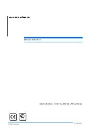
Das Terminal ist auf der Tür des Schaltschranks positioniert und<br />
wird durch eine Polycarbonat-Klappe, die geöffnet werden kann,<br />
geschützt.<br />
The terminal is located on the door of the electrical cabinet and is<br />
protected by an openable polycarbonate cover.<br />
Benützerterminal VGC810<br />
user terminal VGC810<br />
ARIES tech<br />
Die Steuerung verwaltet vollkommen selbständig folgende<br />
Hauptfunktionen:<br />
• die Wärmeregelung des Wassers am Verdampferaustritt (Einheit<br />
ohne Hydronic-Modul) oder unterhalb des Tanks und der Pumpe,<br />
mit der Logik des Neutralbereichs und Leistungsdrosselung auf<br />
4 Leistungsstufen. Alternativ dazu kann der Benutzer wählen,<br />
die Wärmeregelung am Verdampfereintritt oder unten an einem<br />
eventuellen externen Speicher der Einheit (Temperatursonde zu<br />
Lasten des Benutzers) sowie mit Beibehaltung der Logik des<br />
Neutralbereichs oder durch Auswahl der Logik PID auszuführen.<br />
• Einschaltzyklen der Verdichter, Zeitgebung, Ausgleich ihrer<br />
Betriebszeiten und Sättigung jedes Kreislaufs für die Optimierung<br />
der Leistungszahlen in allen Betriebsbedingungen;<br />
• Unloading-Funktion, die die Inbetriebnahme der Anlage sowie den<br />
Betrieb der Einheit auch in ganz anderen als den Nennbedingungen<br />
ermöglicht;<br />
• Funktion “Adaptive Defrosting”, die aufgrund des Vergleichs der<br />
momentanen Leistung des Verdampfers mit der „Target-Leistung“<br />
dieser Einheit (die in den gleichen Betriebsbedingungen durch<br />
die enorme Rechenleistung der Steuerung simuliert wird) die<br />
Abtauzyklen der Wärmepumpen nur aktiviert, wenn diese effektiv<br />
notwendig sind und auf diese Weise eine höhere Energieeffizienz<br />
der Anlage gegenüber den herkömmlichen Abtaulogiken erreicht;<br />
• Verwaltung der elektronischen Thermostatventile (optional);<br />
• Verwaltung des Setpoints:<br />
- “fest” (Standard);<br />
- positiv oder negativ aufgrund der Außenlufttemperatur<br />
„ausgeglichen“;<br />
- “zweifach” durch digitales Signal;<br />
- “Variabel nach Zeiträumen” (4 Zeitspannen), die im internen Timer<br />
zu programmieren sind;<br />
- “variabel durch analoges Signal" 4÷20 mA;<br />
• On/Off für Tages- und/oder Wochen-Zeiträume;<br />
• Verwaltung der Einsatzstufen der Ventilatoren aufgrund des<br />
Verflüssigungsdrucks;<br />
• Kontinuierliche elektronische Regelung der Geschwindigkeit der<br />
Ventilatoren (optional) aufgrund des Verflüssigungsdrucks, zur<br />
Verbesserung der akustischen Leistungen in weniger schweren<br />
Betriebsbedingungen und zur Beibehaltung des Verflüssigungsdrucks<br />
innerhalb der von den Verdichtern geforderten Grenzwerte;<br />
• Verwaltung der Ventilatoren mit “Tages-/Nachtfunktion”, die<br />
es ermöglicht, den Schalldruckpegel der Ventilatoren gemäß<br />
programmierbaren Zeitspannen zu reduzieren;<br />
• Frostschutzfunktion aufgrund der Wasseraustrittstemperatur aus dem<br />
Verdampfer;<br />
• Zeitgebung der Pumpen und Verwaltung der 2. Pumpe in Standby,<br />
mit automatischer Umschaltung bei Störungen und für den Ausgleich<br />
der Betriebszeiten aufgrund:<br />
- Anzahl der Betriebsstunden (Standard);<br />
- On-Off (bei Einschaltung der Einheit wird die Pumpe in Betrieb<br />
gesetzt, die vorher stillstand);<br />
- Manuelle Drehung (kann direkt vom Benutzer ausgewählt werden);<br />
• Zählung der Betriebsstunden der Einheit und der einzelnen<br />
Verdichter, mit Anzeige der Überschreitung der Anzahl der für die<br />
Wartung programmierten Stunden;<br />
• Verwaltung der Umschaltung und des Betriebs im<br />
The controller manages the following main functions independently:<br />
• temperature control of water at the evaporator outlet (units without<br />
hydronic module) or down-line of the tank and the pump, with<br />
neutral zone logic and 4-step capacity control. Alternatively, users<br />
can select temperature control at the evaporator inlet or downline<br />
of an external storage tank (if present), either maintaining<br />
neutral zone logic or choosing PID logic (temperature probe to be<br />
provided by the user);<br />
• compressor start cycles, timing, run times equalisation and<br />
saturation of each circuit to maximise COP values in all operating<br />
conditions;<br />
• unloading function that allows system starting and unit operation<br />
also with parameters that differ significantly from nominal<br />
conditions;<br />
• "Adaptive Defrosting" function which, thanks to the comparison<br />
between the instantaneous evaporator efficiency and the “target”<br />
efficiency of the unit (simulated in the same operating conditions<br />
thanks to the great calculating power of the controller) activates<br />
defrost cycles on heat pumps only when effectively necessary,<br />
making it possible to achieve greater energy efficiency of the system<br />
compared to the use of conventional defrost logic;<br />
• management of electronic thermostatic valves (options);<br />
• set-point management:<br />
- "fixed" (standard);<br />
- “compensated” positively or negatively in accordance with external<br />
air temperature;<br />
- “dual” set by a digital signal;<br />
- “variable in accordance with time bands” (4 time bands)<br />
programmable on the internal timer;<br />
- “variable by analogue signal” 4÷20 mA;<br />
• on/off by daily and/or weekly time bands;<br />
• management of fan activation steps in accordance with condensing<br />
pressure;<br />
• continuous electronic fan speed control (optional) in accordance<br />
with condensing pressure to reduce noise emissions in less<br />
demanding operating conditions and maintain condensing pressure<br />
within the limits required by the compressors;<br />
• management of fans with “day/night” function that makes it possible<br />
to reduce fan noise levels in accordance with programmable time<br />
bands;<br />
• antifreeze control in accordance with the water temperature at the<br />
evaporator outlet;<br />
• pumps timing and management of the 2 nd pump in stand-by, with<br />
automatic changeover in the case of a fault on the main pump and<br />
for equalisation of run times on the basis of:<br />
- number of operating hours (standard);<br />
- on-off (at the time of unit start-up the pump that was previously<br />
stopped is started);<br />
- manual rotation (directly selectable by the user);<br />
• count of operating hours of the unit and individual compressors<br />
with notification when the programmed operating hours before<br />
maintenance are exceeded;<br />
• management of changeover and operation in heat recovery<br />
mode;<br />
• management of alarm messages, including:<br />
- low evaporation pressure alarm;<br />
8
Wärmerückgewinnungsmodus;<br />
• Verwaltung der Alarmmeldungen wie:<br />
- Niederdruckalarm Verdampfung;<br />
- Hochdruckalarm Verflüssigung;<br />
- Einschritt der Wärmeschutzvorrichtungen der Verdichter;<br />
- Einschritt der Wärmeschutzvorrichtungen der Ventilatoren;<br />
- Einschritt der Wärmeschutzvorrichtungen der Pumpen (optional);<br />
- Einschritt des Differentialdruckschalters für den Mangel des<br />
Wasserflusses am Verdampfer;<br />
- Frostschutzalarm;<br />
- Über- und Untertemperaturalarme am Wasserein- und –austritt;<br />
- Störung der Stromversorgung max./min. Spannung (+/- 10 %) und<br />
Phasensequenz.<br />
Durch das Display können außer den Alarmen folgende Hauptanzeigen<br />
erscheinen:<br />
• Verdampfungs- und Verflüssigungsdruck jedes Kreislaufs;<br />
• Außenluft- und Wassereintritts- und -austrittstemperatur;<br />
• Status der digitalen Ein- und Ausgänge;<br />
• Alarmhistorik;<br />
• Mehrsprachenauswahl (italienisch, englisch, französisch, deutsch<br />
und spanisch).<br />
Weiterhin steht für die Fernmeldung eines Generalalarms ein<br />
potentialfreier Kontakt zur Verfügung.<br />
Der Kontroller verfügt über einen Serienausgang RS485 mit<br />
Standardkommunikationsprotokoll ModBUS, das die Verbindung mit durch<br />
das System Integrators Dritter entwickelter Anwendungen für die sowohl<br />
lokale als auch fern liegende Steuerung und Überwachung ermöglicht.<br />
Der Kontroller verfügt auch über einen Ethernet-Port mit zur Ansicht<br />
vorgeladenen HTML-Überwachungsseiten, Abfrage und Änderung der<br />
Parameter der Einheit durch die Verbindung mit einem Betriebsnetz<br />
oder durch Internet.<br />
Es ist möglich, die Parallelverbindung mehrerer Einheiten (bis 4) durch<br />
das lokale Netz auszuführen, indem die erste von der Steuerung als<br />
"Master-" und die anderen als "Slave-" Einheiten eingestellt werden.<br />
Der Benutzer kann die Einheit durch das Terminal der Master-Einheit<br />
oder durch das Benutzer-Fernterminal verwalten.<br />
15. Optionen, Kits und Sonderausführungen<br />
- high condensing pressure alarm;<br />
- compressor thermal protections trip alarm;<br />
- fan thermal protections trip alarm;<br />
- pump thermal protections trip alarm (optional);<br />
- differential pressure switch trip alarm due to insufficient water flow<br />
to the evaporator;<br />
- antifreeze alarm;<br />
- high and low temperature water inlet and outlet alarms;<br />
- power supply maximum/minimum voltage (+/- 10 %) and phase<br />
sequence anomaly.<br />
In addition to alarms, the display can also present the following main<br />
information:<br />
• condensing and evaporation pressure values of each circuit;<br />
• inlet and outlet water temperature and external air;<br />
• status of digital inputs and outputs;<br />
• alarms history;<br />
• language selection (Italian, English, French, German, Spanish).<br />
In addition, a voltage-free contact is provided for remotisation of a<br />
general alarm signal.<br />
The controller has a RS485 serial output with standard ModBUS<br />
communication protocol for the connection to applications developed<br />
by third party System Integrators, for local and remote control and<br />
monitoring.<br />
The controller also has an Ethernet port with preloaded HTML<br />
supervision pages to display, interrogate and modification parameters<br />
of the unit through a connection to the company’s network or the<br />
internet.<br />
Several units (up to 4) can be connected in parallel on a LAN local<br />
network, by setting the first one as the "master" unit and the others as<br />
"slave" units on the controller. The user can manage the group of units<br />
by means of the master unit terminal or by means of the replicated<br />
remote terminal.<br />
15. Options, kit and special designs<br />
Optionen (Die Optionen müssen bei der Ausstellung des Auftrages<br />
spezifiziert werden, denn sie werden im Herstellerwerk installiert):<br />
• Wärmerückgewinner (siehe entsprechenden Abschnitt);<br />
• integriertes Hydronic-Modul (siehe entsprechenden Abschnitt);<br />
• 2. Pumpe in Standby, mit automatischer Umschaltung im Falle einer<br />
Störung und für den Ausgleich der Betriebszeiten, Absperrhähne<br />
oberhalb und unterhalb jeder Pumpe und Rückschlagventile am Auslass;<br />
• Version mit nur einem Pumpenmodul (1 oder 2 Pumpen):<br />
Gegenüber der Version mit vollständigem Modul sind kein<br />
Speichertank, Ausdehnungsgefäß und Sicherheitsventil montiert;<br />
• Verdichter-Frostschutzheizung in der Kühlerversion nur für<br />
Kältebetrieb;<br />
• Absperrhähne am Ein- und Auslass an jedem parallel verbundenen<br />
Verdichterpaar;<br />
• Frostschutzheizung: An den Verdampfern montierte, eventuelle<br />
Tauchpumpe/n und Rückgewinnungswärmetauscher, die von<br />
der elektronischen Steuerung auf der Einheit aufgrund der<br />
Außenlufttemperatur im eventuellen Speichertank gesteuert werden<br />
und deren Temperaturregelung aufgrund der Wassertemperatur erfolgt;<br />
• Metallmaschenfilter zum Schutz der Register;<br />
• Register mit Lackschutzbehandlung; Vorlackierte Aluminiumlamellen<br />
mit organischer Verkleidung auf der Basis von Epoxy-Acryl-Harzen,<br />
danach wird der gesamte Verflüssiger vollständig mit wärmehärtendem<br />
Pulver auf der Basis von vernetzten Polyesterharzen verkleidet;<br />
• Kontinuierliche elektronische Regelung mit Phasenschnitt für die<br />
Kontrolle des Verflüssigungsdrucks und für die Reduzierung des<br />
Schalldruckpegels in den häufigsten Betriebsbedingungen. Immer in<br />
der Version -20 °C Außentemperatur vorhanden;<br />
Options (the options must be specified at the time of the order<br />
because they are installed in the factory):<br />
• heat recovery exchangers (see specific heading);<br />
• integral hydronic module (see specific heading);<br />
• 2 nd pump in stand-by, with automatic changeover in the case of<br />
faults and for equalisation of run times, shut-off valves up-line<br />
and down-line of each pump and check valves on the pressure<br />
line;<br />
• version with pumping module only (1 or 2 pumps): unlike the<br />
version with the complete module, this version is not equipped with<br />
storage tank, expansion vessel and relief valve;<br />
• compressor crankcase heaters in cooling-only chiller versions;<br />
• shut-off valves on discharge and suction lines on each pair of<br />
compressors connected in parallel;<br />
• anti-freeze heater: wrapped around the evaporator, pump/s and<br />
recovery exchangers if present, controlled by the on-board electronic<br />
controller in accordance with ambient air temperature; there is also<br />
an immersion heater in the storage tank (if present) with temperature<br />
control in relation to water temperature;<br />
• metal mesh protection filters for coils;<br />
• coils with protective paint treatment: prepainted aluminium fins<br />
with an epoxy-acrylic resin based organic coating; subsequently<br />
the entire condenser is protected with a reticulated polyester resin<br />
thermosetting powder coating;<br />
• continuous phase cut-off electronic speed control, both for<br />
condensing pressure control and reduction of noise emission levels<br />
in the most frequent duty conditions. Always present in the - 20 °C<br />
ambient air temperature version;<br />
ARIES tech<br />
9
• Elektronische Thermostatventile (nur für die Kalt-Versionen und<br />
serienmäßig für die Version -20 °C Außentemperatur verfügbar): Diese<br />
Thermostatventile ermöglichen die Verbesserung der Kälteleistungen in<br />
einem weiteren Betriebsfeld als die mechanischen Thermostatventile<br />
sowohl durch Optimierung und Reduzierung des Gasüberhitzungswertes<br />
beim Ansaugen der Verdichter als auch bei der Reduzierung der<br />
Wassertemperaturschwankungen infolge von plötzlichen Änderungen<br />
der Wärmelast. Die Wahl des elektronischen Thermostatventils schließt<br />
die Wahl der elektronischen Regelung der Ventilatoren ein;<br />
• Vorrichtung zur Drehfeldüberwachung: Relais für max./min.<br />
Spannung (±/- 10%), Fehlen und Kontrolle der Phasensequenz;<br />
• Blindstromkondensator cos = 0,93.<br />
• electronic thermostatic valves (only available in the cooling-only<br />
version and standard in the -20 °C external air temperature version):<br />
these valves allow an improvement in cooling performance in an<br />
operating range that is significantly wider than that of mechanical<br />
thermostatic valves, both by optimizing and reducing the superheating<br />
value of gas drawn in by the compressor and by reducing water<br />
temperature fluctuations caused by constant and sudden changes in<br />
the thermal load. The choice of the electronic thermostatic solenoid<br />
valve is entails the choice of electronic fan speed control;<br />
• phase monitor device: minimum/maximum voltage (+/- 10%) relay,<br />
missing phase and phase sequence monitoring;<br />
• capacitors for compressor power factor correction at cos = 0,93.<br />
ARIES tech<br />
Kit (die Kits sind Zubehörteile, die als separates Frachtstück, generell<br />
gleichzeitig mit der Einheit, geliefert werden und durch den Kunden<br />
installiert werden. Sie können auch später als Ersatzteile, Änderungs-<br />
Kit, zur Vervollständigung usw. geliefert werden):<br />
• Einfache Fernsteuerung: Bestehend aus einem On/Off-Schalter,<br />
einem Sommer-/Winterschalter (nur Wärmepumpen), einer grünen<br />
Betriebs-LED und einer roten LED für Generalalarm in einem<br />
Plastikgehäuse für die Wandmontage, und aus 3 m Kabel für die<br />
Verbindung mit der Einheit;<br />
• Reproduziertes Benutzer-Fernterminal: Das Terminal, das wie<br />
jenes und zusätzlich zu dem an der Einheit ist, kann bis zu einer<br />
Entfernung von 150 m separat angebracht werden. Es verfügt über<br />
die Schnittstellenkarte mit der Steuerung der Einheit. Das Ganze ist<br />
in ein Plastikgehäuse für Wandmontage montiert;<br />
• Serielle Anschlüsse an die Überwachungssysteme: Für die örtliche<br />
Supervision der Einheit über Personal Computer oder BMS-Systeme;<br />
die Kits schließen nicht die Verbindungskabel und die BMS-Programme<br />
ein, die vom Kunden zu erbringen sind (für weitere Informationen und<br />
technische Einzelheiten wenden Sie sich bitte unsere Verkaufsbüros<br />
und/oder lesen die Anleitungen der entsprechenden Verbindungs-Kits):<br />
• Überwachung xWEB (mit oder ohne integrierten Modem): xWEB stellt<br />
eins der höchst entwickelten Überwachungs- und Kontrollsysteme dar,<br />
die heute auf dem Markt verfügbar sind, und wird mit den modernsten<br />
Technologien verwendet, die auf die „Internet-Welt“ anwendbar sind.<br />
xWEB ist ein mit dem Betriebssystem μc-Linux ausgestatteter Server, der<br />
alle Informationen, die von den Steuerungen kommen und mit ihnen<br />
verbunden und an der seriellen Leitung durch Kommunikationsprotokoll<br />
Modbus-Rtu angeschlossen sind, liest, archiviert und kontrolliert.<br />
Dieser stellt sowohl in lokaler Verbindung (durch ein serielles nicht<br />
mitgeliefertes Kabel) als auch in Fernverbindung im Webseitenformat<br />
folgende Hauptfunktionen zur Verfügung:<br />
- Überwachung, Archivierung und Verwaltung der Systemaktivitäten<br />
und der Alarme;<br />
- Graphische und Tabellenverwaltung der Werte, die während des<br />
Betriebs registriert wurden;<br />
- Fernänderung der Betriebsparameter.<br />
• Schwingungsdämpfer;<br />
• Metallmaschenfilter zum Schutz der Register;<br />
• “Victaulic-Anschlüsse”: mit Anzugsbacken, Dichtungen und zu<br />
schweißender Stutzen (für Modelle von 080 bis 140 verfügbar, die<br />
mit integriertem Hydronic-Modul ausgestattet sind).<br />
Sonderausführungen (es handelt sich um die am häufigsten<br />
angeforderten Besonderheiten, die normalerweise nicht detailliert in<br />
unseren <strong>Katalog</strong>en beschrieben werden; die Durchführbarkeit solcher<br />
Ausführungen muss für jeden Einzelfall mit unseren Verkaufsbüros vor<br />
dem Auftrag untersucht, bestätigt und ausgewertet werden):<br />
• Elektronische Vorrichtung “Soft-Starter” zur Reduzierung der<br />
Anlaufströme;<br />
• hoch effiziente und sehr leise Ventilatoren mit Motoren mit integriertem<br />
Inverter und EC-Technologie (mit Dauermagneten und elektronischer<br />
Umschaltung);<br />
• Register mit Schutzbehandlung Typ Blygold;<br />
• Kupfer-Kupfer-Register mit Rohren und Lamellen aus Kupfer und<br />
Halterungen aus Messing;<br />
• Druckregelventile für Rückgewinnungstauscher;<br />
• Wärmerückgewinner in den Wärmepumpen.<br />
Kits (the kits are supplied separately, generally at the same time of<br />
the unit, and installed by the user. They can be supplied later as spare<br />
parts, modification kits, completion kits, etc.):<br />
• simple remote control: composed of an ON/OFF switch, summer/<br />
winter changeover switch (heat pumps only), green run LED and<br />
red general alarm LED, mounted on a plastic wall-mounting<br />
enclosure, plus 3 metres of cable for connection to the unit;<br />
• replicated remote user terminal: installable at a distance of up<br />
to 150 metres, the replicated remote control is composed of a<br />
terminal that is identical to and supplied in addition to the terminal<br />
mounted on board the unit, and a board for interface with the<br />
unit controller, accommodated in a specific plastic wall-mounting<br />
enclosure;<br />
• serial connections to supervision systems: allow connection of the<br />
unit to local supervision systems by means of a PC or with BMS<br />
systems; the kits do not include the connection cables and the BMS<br />
programs, which are to be provided by the customer (for further<br />
information and technical details refer to the manual of the relative<br />
connection kits):<br />
• xWEB supervision (with or without integrated module): xWEB<br />
is one of the most advanced monitoring, control and supervision<br />
systems currently available on the market, utilising cutting-edge<br />
technology compatible with the world of the “Internet”. The xWEB<br />
is a server provided with a μc-Linux operating system, that reads,<br />
stores and checks all the information coming in from the controllers<br />
connected to it and connected to the serial line by means of the<br />
Modbus-Rtu communication protocol. It provides access to the<br />
following functions both by means of a local connection (by means<br />
of serial cable - not supplied) and using a remote connection in Web<br />
page format:<br />
- monitoring, filing and management activity of the system and the<br />
alarms;<br />
- graphic and table management of the parameters recorded during<br />
operation;<br />
- remote handling of the parameters editing.<br />
• anti-vibration mounts;<br />
• metal mesh protection filters for coils;<br />
• "Victaulic" joint: complete of bracketing clamps, wet seal gaskets<br />
and welding stud pipe (available from models 080 to 140 equipped<br />
with integrated hydronic module).<br />
Special designs (a selection of the most popular special features, normally<br />
not described in detail in our catalogues; the feasibility of special designs<br />
must be assessed, confirmed, and priced on a case by case basis in<br />
communication with our sales offices before placing the order):<br />
• electronic “soft-starter” device for limitation of peak current;<br />
• high efficiency and very low noise emission fans, with integrated<br />
inverter motors and CE technology (with permanent magnets and<br />
electronic changeover);<br />
• coils with Blygold protective treatment;<br />
• copper-copper coils with copper tubes and fins and brass shoulders;<br />
• pressure control valves for recovery exchangers;<br />
• recovery exchangers on heat pumps.<br />
10
LEITFADEN ZUR AUSWAHL - SELECTION GUIDE<br />
Die Auswahl eines Produktes der Serie ARIES tech oder HARIES<br />
tech erfolgt durch die Tabelle „Leitfaden zur Auswahl“ und die<br />
Datentabellen jeder einzelnen Einheit. Für die korrekte Auswahl eines<br />
Kaltwassererzeugers ist neben dem hier folgenden notwendig:<br />
1) Prüfen, dass die Einsatzgrenzen in der Tabelle „Einsatzgrenzen“<br />
eingehalten sind;<br />
2) Prüfen, dass die abzukühlenden Wasserdurchflussmengen zwischen<br />
den in der Tabelle „Allgemeine Angaben“ jeder Einheit angegebenen<br />
Mindest- und Höchstwerten liegen; zu niedrige Durchflussmengen<br />
verursachen einen laminaren Fluss mit der daraus entstehenden<br />
Gefahr einer Eisbildung und einer schlechten Regelung; zu<br />
hohe Werte verursachen dagegen zu starke Druckverluste und<br />
möglicherweise einen Rohrbruch;<br />
3) Falls die Einheit mit einer Wasseraustrittstemperatur unter 5 °C<br />
und unter einer Außentemperatur von 0 °C verwendet wird, ist<br />
Äthylenglykol oder ein anderes Frostschutzmittel hinzuzugeben.<br />
Konsultieren Sie die Tabelle „Wasser- und Äthylenglykollösungen“,<br />
um die notwendige Menge Äthylenglykol zu bestimmen und die<br />
Reduzierung der Kälteleistung, den Anstieg der Leistungsaufnahme<br />
durch die Verdichter und den Anstieg der Druckverluste am<br />
Verdampfer zu bewerten, die durch das Vorhandensein des<br />
Äthylenglykols entstehen.<br />
4) Wenn die Einheit in einer Höhe über 500 m installiert wird, muss<br />
die Reduzierung der Kälteleistung und die Zunahme der vom<br />
Verdichter aufgenommenen Leistung mit den Koeffizienten der<br />
Tabelle „Korrekturkoeffizienten der Verflüssiger“ bewertet werden;<br />
For ARIES tech and HARIES tech selecting use the table “Selection<br />
guide” and the table “Performance data” relative to each unit. For a<br />
correct chiller selection it is also necessary:<br />
1) Check the operational limits as indicated in the chart “Working<br />
limits”;<br />
2) Verify that the cool water flow is between the minim and maximum<br />
values of water flow which are described in the “General data”<br />
table. A very low flow can cause laminar flow and thus danger of<br />
ice formation and wil cause poor unit control. A very high flow can<br />
cause greater pressure drops and the possibility of tube failure inside<br />
the evaporator;<br />
3) For working temperatures under 5 °C outlet water and 0 °C external<br />
air temperature it is necessary to add ethylene glycol or any other<br />
antifreeze additives. Consult the chart “Solutions of water and<br />
glycol” to determine the necessary quantity of ethylene glycol, the<br />
reduction of cooling capacity, the increase of power absorbed by<br />
the compressors, the increase of evaporator pressure drop due to the<br />
presence of the ethylene glycol;<br />
4) If the chiller is to be installed at an altitude higher than 500 m, you<br />
must calculate the cooling capacity reduction and the increase of<br />
compressor absorbed power by checking the coefficients as shown<br />
in the chart “Condenser correction factors”;<br />
5) When the difference in temperature between water inlet and outlet<br />
is different from 5 °C, the cooling capacity and the absorbed power<br />
must be connected using the table “correction factors T 5 °C.<br />
5) Sollte der Temperaturunterschied zwischen Wasserein- und –austritt<br />
anders als 5 °C sein, sind die Kälteleistung und die aufgenommene<br />
Leistung durch Verwendung der Tabelle „Korrekturkoeffizienten T<br />
5 °C“ zu korrigieren.<br />
ARIES tech<br />
11
ARIES tech<br />
LEISTUNGEN DER EINHEIT NUR FÜR KÄLTEBETRIEB - PERFORMANCE DATA COOLING MODE<br />
KÄLTELEISTUNG - COOLING CAPACITY (kW)<br />
Außenlufttemperatur - external air temperature (°C) t max (1) Pf (2)<br />
AST 070<br />
AST 080<br />
AST 090<br />
AST 100<br />
AST 110<br />
AST 120<br />
AST 130<br />
AST 140<br />
25 30 35 38 40 42 (°C) (kW)<br />
N 182 172 162 155 151 146 45,0 139<br />
SN 176 166 156 149 145 140 42,0 140<br />
SSN 177 167 156 150 145 140 42,0 140<br />
H 190 181 171 164 160 156 49,0 140<br />
N 219 208 196 188 183 178 46,0 167<br />
SN 211 199 187 179 174 169 43,0 166<br />
SSN 205 193 180 172 167 - 40,0 167<br />
H 223 212 200 193 188 182 49,0 163<br />
N 238 226 213 205 199 193 46,0 182<br />
SN 229 216 203 195 189 183 42,0 183<br />
SSN 223 211 197 189 183 - 40,0 183<br />
H 242 230 217 209 204 198 48,0 181<br />
N 252 239 225 216 210 204 46,0 192<br />
SN 242 228 214 205 199 193 42,0 193<br />
SSN 236 222 207 198 192 - 40,0 192<br />
H 257 244 230 222 216 210 48,0 191<br />
N 281 266 250 240 233 226 45,0 215<br />
SN 270 255 238 228 220 213 42,0 213<br />
SSN 272 256 240 229 222 215 42,0 215<br />
H 295 281 265 255 249 242 49,0 216<br />
N 308 291 272 260 252 244 44,0 236<br />
SN 294 276 257 244 236 - 40,0 236<br />
SSN 296 278 259 247 - - 39,0 243<br />
H 325 309 291 280 272 264 48,0 239<br />
N 349 331 312 299 291 282 46,0 264<br />
SN 336 317 296 284 275 266 42,0 266<br />
SSN 322 302 281 268 - - 39,0 264<br />
H 356 338 319 307 299 290 48,0 263<br />
N 372 352 331 317 308 298 45,0 284<br />
SN 356 335 313 299 290 - 41,0 285<br />
SSN 339 318 295 281 - - 39,0 276<br />
H 381 361 340 327 317 308 48,0 279<br />
(1) Max. Außenlufttemperatur, auf die Kaltwasseraustrittstemperatur bezogen: 12 °C, Kaltwasseraustritt: 7 °C.<br />
Maximum external air temperature, refer to cooled water inlet 12 °C and outlet water temperature condition at 7 °C.<br />
(2) Kälteleistung bei max. Außenlufttemperatur. Cooling capacity refer to the maximum external air temperature.<br />
Zur Auswahl des Modells des Kaltwassererzeugers, in die Spalte mit der maximalen Außenlufttemperatur des Installationsraums des Kaltwassererzeugers und auf die<br />
Zeile mit der verlangten Kälteleistung gehen. Die in der Tabelle angegebenen Leistungen beziehen sich auf folgende Bedingungen: Kaltwasserein-/-austrittstemperatur:<br />
12/7 °C. Für andere Bedingungen und sonstige Merkmale der Einheit, siehe die internen Tabellen des gewählten Modells. Wenn die Außenlufttemperatur höher ist als<br />
„t max“, blockiert sich die Einheit nicht, sondern es greift das „Unloading-System“ zur Leistungsdrosselung ein.<br />
To select the chiller model you must choose the column that indicates the maximum external air temperature in which the chiller will be installed and the line<br />
with the cooling capacity requested. The capacities shown in the table refer to the following conditions: inlet/outlet water cooled temperature 12/7 °C. For other<br />
conditions and other unit specifications, consult the internal tables relative to the model selected. When the external air temperature is higher than the "t max" the<br />
unit doesn't stop but the "unloading" system capacity control is activated.<br />
12
LEISTUNGEN DER WÄRMEPUMPE - PERFORMANCE DATA HEAT PUMP<br />
KÄLTELEISTUNG - COOLING CAPACITY (kW)<br />
Außenlufttemperatur - external air temperature (°C) t max (1) Pf (2)<br />
HAST 070<br />
HAST 080<br />
HAST 090<br />
HAST 100<br />
HAST 110<br />
HAST 120<br />
HAST 130<br />
HAST 140<br />
25 30 35 38 40 42 (°C) (kW)<br />
N 184 175 165 159 154 150 48,0 136<br />
SN 179 170 160 153 149 144 45,0 138<br />
SSN 175 165 155 148 144 139 43,0 137<br />
N 218 207 195 188 183 178 48,0 162<br />
SN 211 199 188 180 175 170 45,0 162<br />
SSN 205 194 182 174 169 163 42,0 163<br />
N 231 219 206 198 192 187 46,0 175<br />
SN 224 212 199 191 185 179 42,0 179<br />
SSN 227 215 202 194 188 182 43,0 179<br />
N 245 232 218 209 203 197 46,0 185<br />
SN 237 224 210 201 195 189 42,0 189<br />
SSN 240 227 213 204 198 192 43,0 189<br />
N 279 264 249 239 232 225 46,0 211<br />
SN 270 255 239 229 222 215 43,0 211<br />
SSN 272 257 242 231 225 218 44,0 210<br />
N 318 302 284 273 266 258 47,0 238<br />
SN 307 290 272 261 253 245 44,0 237<br />
SSN 298 281 262 251 243 235 42,0 235<br />
N 343 325 306 294 286 277 47,0 255<br />
SN 331 312 293 280 272 263 43,0 258<br />
SSN 317 298 278 265 257 - 40,0 257<br />
N 372 353 332 319 310 301 46,0 282<br />
SN 357 337 315 302 293 283 43,0 279<br />
SSN 344 324 302 288 279 - 40,0 279<br />
WÄRMELEISTUNG - HEATING CAPACITY (kW)<br />
Außenlufttemperatur / relative Feuchtigkeit (°C/RH)<br />
external air temperature / relative umidity (°C/RH) t min (3) Ph (4)<br />
HAST 070<br />
HAST 080<br />
HAST 090<br />
HAST 100<br />
HAST 110<br />
HAST 120<br />
HAST 130<br />
HAST 140<br />
-5 / 87% 0 / 87% 5 / 87% 7 / 87% 12 / 87% 15 / 87% (°C) (kW)<br />
N 134 152 170 179 201 216 -7 128<br />
SN 131 148 166 174 196 211 -6 128<br />
SSN 129 145 163 170 191 205 -5 129<br />
N 160 181 204 214 241 259 -7 152<br />
SN 156 176 198 208 233 251 -6 152<br />
SSN 153 172 194 203 228 245 -5 153<br />
N 172 195 219 230 259 278 -6 168<br />
SN 168 190 214 224 252 271 -6 164<br />
SSN 169 191 215 225 253 272 -6 165<br />
N 182 206 232 243 273 294 -6 177<br />
SN 178 201 226 237 266 286 -5 178<br />
SSN 178 202 227 238 267 287 -5 178<br />
N 206 234 263 276 310 334 -6 201<br />
SN 201 228 257 269 302 325 -5 201<br />
SSN 206 233 262 275 309 332 -6 201<br />
N 236 268 302 317 357 384 -8 219<br />
SN 230 261 294 308 346 372 -7 219<br />
SSN 225 255 287 300 337 363 -6 220<br />
N 254 287 323 339 381 409 -7 241<br />
SN 247 279 314 328 369 397 -6 241<br />
SSN 241 272 306 320 359 386 -5 241<br />
N 282 318 357 374 421 453 -8 262<br />
SN 274 308 345 361 406 437 -7 261<br />
SSN 267 300 335 351 394 424 -6 261<br />
(1) Max. Außenlufttemperatur, auf die Kaltwasseraustrittstemperatur bezogen: 12 °C, Kaltwasseraustritt: 7 °C<br />
Maximum external air temperature, refer to cooled water inlet 12 °C and outlet water temperature condition at 7 °C.<br />
(2) Kälteleistung bei max. Außenlufttemperatur. Cooling capacity refer to the maximum external air temperature.<br />
(3) Mindestaußenlufttemperatur, auf die Wassereintrittstemperatur bezogen: 40 °C und Wasseraustrittstemperatur 45 °C.<br />
Minimum external air temperature, refer to water inlet temperature 40 °C and outlet water temperature condition at 45 °C.<br />
(4) Wärmeleistung bei min. Außenlufttemperatur. Heating capacity refer to the minimum external air temperature.<br />
Zur Auswahl des Modells des Kaltwassererzeugers, in die Spalte mit der maximalen Außenlufttemperatur des Installationsraums des Kaltwassererzeugers und<br />
auf die Zeile mit der verlangten Kälteleistung gehen. Die in der Tabelle angegebenen Kälteleistungen beziehen sich auf folgende Bedingungen: Kaltwasserein-<br />
/-austrittstemperatur: 12/7 °C. Für andere Bedingungen und sonstige Merkmale der Einheit, siehe die internen Tabellen des gewählten Modells. Wenn die<br />
Außenlufttemperatur höher als „t max“ oder niedriger als „t im“ ist, blockiert sich die Einheit nicht, sondern es greift das „Unloading-System“ zur Leistungsdrosselung<br />
ein. To select the chiller model you must choose the column that indicates the maximum external air temperature in which the chiller will be installed and the line<br />
with the cooling capacity requested. The cooling capacity shown in the table refer to the following conditions: inlet/outlet water cooled temperature 12/7 °C. For<br />
other conditions and other unit specifications, consult the internal tables relative to the model selected. When the external air temperature is higher than the "t max"<br />
or lower the "t min" the unit doesn't stop but the "unloading" system capacity control is activated.<br />
ARIES tech<br />
Zur Auswahl des Modells der Wärmepumpe, in die Spalte mit der minimalen Umgebungstemperatur des Installationsraums der Wärmepumpe und auf die Zeile mit der<br />
verlangten Wärmeleistung gehen. Die in der Tabelle angegebenen Wärmeleistungen beziehen sich auf folgende Bedingungen: Ein-/-austrittstemperatur des geheizten<br />
Wassers: 40/45 °C. Für andere Bedingungen und sonstige Merkmale der Einheit, siehe die internen Tabellen des gewählten Modells. Wenn die Außenlufttemperatur<br />
höher als „t max“ oder niedriger als „t im“ ist, blockiert sich die Einheit nicht, sondern es greift das „Unloading-System“ zur Leistungsdrosselung ein. To select the heat<br />
pump model you must choose the column that indicates the minimum external air temperature in which the heat pump will be installed and the line with the heating<br />
capacity requested. The heating capacity shown in the table refer to the following conditions: inlet/outlet heat water temperature 40/45 °C. For other conditions and<br />
other unit specifications, consult the internal tables relative to the model selected. When the external air temperature is higher than the "t max" or lower the "t min"<br />
the unit doesn't stop but the "unloading" system capacity control is activated.<br />
13
LEISTUNGEN UND TECHNISCHE DATEN - PERFORMANCE AND TECHNICAL DATA<br />
ALLGEMEINE DATEN - GENERAL DATA<br />
AST - HAST<br />
ARIES tech<br />
HARIES tech<br />
N SN SSN H N SN SSN<br />
Kältekreise Cooling circuits N° 2 2<br />
Verdichter Compressors N° 2+2 2+2<br />
Leistungsstufen Capacity control % 0 - 25 - 50 - 75 - 100 0 - 25 - 50 - 75 - 100<br />
ESEER (1) ESEER (1) - 3,84 4,16 4,65 4,07 3,87 4,22 4,56<br />
IPLV (2) IPLV (2) - 4,08 4,50 5,05 4,25 4,12 4,53 4,98<br />
Stromversorgung<br />
Electrical power supply<br />
Leistung Power V/Ph/Hz 400 ± 10% / 3 / 50 400 ± 10% / 3 / 50<br />
Hilfskreise Auxiliary V/Ph/Hz 24 - 230 ± 10% / 1 / 50 24 - 230 ± 10% / 1 / 50<br />
Verflüssigerregister<br />
Condenser coil<br />
Register Coils N° 2 2 2 2 2 2 2<br />
Reihen Rows N° 2 2 3 3 3 3 3<br />
Gesamtvorderfläche Total frontal surface m 2 7,26 7,26 7,26 7,26 7,26 7,26 7,26<br />
Axialventilatoren<br />
Axial fans<br />
Ventilatoren Fans N° 4 4 4 4 4 4 4<br />
Luftdurchfluss im einzelnen Register Single coil air flow m 3 /h 43125 32469 20781 39843 44125 33243 26800<br />
Leistung (einzeln) Power (each) kW 2 1,25 0,7 2 2 1,25 0,77<br />
Plattenverdampfer<br />
Evaporator plate type<br />
Minimaler Durchfluss Verdampfer Min/max evaporator flow rate m 3 /h 13,0 / 42,1 13,0 / 42,1<br />
Wasservolumen Verdampfer Evaporator water volume I 10,1 10,1<br />
Abmessungen und Gewichte im Betrieb Dimensions and installed weight<br />
Breite Width mm 2188 2188 2188 2188 2188 2188 2188<br />
Tiefe Length mm 3495 3495 3495 3495 3495 3495 3495<br />
Höhe Height mm 1989 1989 1989 1989 1989 1989 1989<br />
Gewicht ohne Behälter und Pumpe Weight without tank and pump kg 1765 1765 1813 1765 1924 1924 1934<br />
Gewicht mit Behälter und doppelter P3 Weight with tank and double P3 kg 2222 2222 2270 2222 2324 2324 2334<br />
(1) Gemäß den Bedingungen EECCAC kalkuliert; calculated according to EECCAC conditions.<br />
(2) Gemäß Standard ARI 550/590-2003 kalkuliert; calculated according to Standard ARI 550/590-2003.<br />
ELEKTRISCHE LEISTUNGSAUFNAHMEN - ELECTRICAL DATA<br />
AST - HAST<br />
ARIES tech<br />
HARIES tech<br />
Ohne Pumpe - Without pump Pumpe P2 - Pump P2 Pumpe P3 - Pump P3 Ohne Pumpe - Without pump Pumpe P2 - Pump P2 Pumpe P3 - Pump P3<br />
FLI (kW) FLA (A) ICF 1 (A) ICF 2 (A) FLI (kW) FLA (A) ICF 1 (A) ICF 2 (A) FLI (kW) FLA (A) ICF 1 (A) ICF 2 (A) FLI (kW) FLA (A) ICF 1 (A) ICF 2 (A) FLI (kW) FLA (A) ICF 1 (A) ICF 2 (A) FLI (kW) FLA (A) ICF 1 (A) ICF 2 (A)<br />
N 75 135 277 277 78 141 283 283 81 145 287 287 75 135 277 277 78 141 283 283 81 145 287 287<br />
SN 72 128 258 258 75 134 265 265 78 138 269 269 72 128 258 258 75 134 265 265 78 138 269 269<br />
SSN 70 123 253 253 73 129 259 259 76 134 264 264 70 125 255 255 73 131 261 261 76 135 265 265<br />
H 75 135 277 277 78 141 283 283 81 145 287 287 -<br />
FLI = Unter den Betriebslimitbedingungen aufgenommene Höchstleistung; max power absorbed in the working limits condition; FLA = Unter den<br />
Betriebslimitbedingungen aufgenommener Höchststrom; max current absorbed in the working limits condition; ICF1 = Anlaufstrom beim Start des letzten Verdichters<br />
unter Betriebslimitbedingungen; start-up current at the start of the last compressor in the working limits condition with fans with step regulation; ICF2 = corrente di<br />
spunto alla partenza dell'ultimo compressore nelle condizioni limite di funzionamento con regolazione elettronica dei ventilatori; start-up current at the start of the<br />
last compressor in the working limits condition with electonic fans control regulator.<br />
SCHALLPEGEL - SOUND LEVELS<br />
AST - HAST<br />
ARIES tech 070<br />
ARIES tech<br />
Oktavenbänder Octave bands (Hz)<br />
Leistung Druck<br />
63 125 250 500 1000 2000 4000 8000 Power Pressure<br />
Schallleistungspegel Sound power level dB(A) dB (A) dB (A)10m<br />
N 58,1 75,7 87,2 88,1 88,1 85,2 77,3 66,9 93,6 65,6<br />
SN 51,8 69,4 80,9 81,8 81,8 78,9 71,0 60,6 87,2 59,2<br />
SSN 54,4 64,0 72,5 72,8 74,3 69,9 61,6 49,4 78,9 50,9<br />
H 57,2 74,8 86,3 87,2 87,2 84,3 76,4 66,0 92,6 64,6<br />
Abstand (1)<br />
Distance (1) KdB<br />
L (m)<br />
1 15<br />
3 10<br />
N 57,2 74,8 86,3 87,2 87,2 84,3 76,4 66,0 92,6 64,6<br />
5 6<br />
HARIES tech SN 50,6 68,2 79,7 80,6 80,6 77,7 69,8 59,4 86,0 58,0<br />
10 0<br />
SSN 55,8 65,4 73,9 74,2 75,6 71,2 62,8 50,5 80,3 52,3<br />
Schallleistung: aufgrund der Messungen gemäß der Norm ISO 3744 bestimmt. Schalldruck bei 10 m: auf freiem Feld auf einer Spiegelfläche in 10 m Entfernung von<br />
der Verflüssigerregisterseite und in 1,6 m Höhe gegenüber der Auflagefläche der Einheit. Toleranzwerte ± 2 dB. Die Schalldruckpegel beziehen sich auf den Betrieb der<br />
Einheit mit Volllast in Nennbetriebsbedingungen und mit Umwälzpumpe. (1) Die folgende Formel verwenden, um den Schalldruckpegel bei einer anderen Entfernung zu<br />
berechnen: dB(A)L=dB(A)10m+Kdb. Sound power: determined on the basis of measurements taken in accordance with the standard ISO 3744. Sound pressure at 10 m:<br />
Average value obtained in free field on a reflective surface at a distance of 10 m from the side of the condenser coils and at a height of 1.6 m from the unit support base.<br />
Values with tolerance +/- 2. The sound levels refer to operation of the unit under full load in nominal conditions and with circulation pump. (1) To calculate a different<br />
distance of the sound pressure level, use the formula: dB(A)L=dB(A)10m+Kdb.<br />
HYDRAULIKANLAGE (OPTIONAL) - HYDRAULIC GROUP (OPTIONAL)<br />
AST - HAST<br />
Wasserdurchfluss Water flow rate m 3 /h 13,0 17,8 22,7 27,6 32,5 37,4 42,1<br />
Druckverlust des Verdampfers Evaporator pressure drop kPa 10,3 19,5 31,7 46,8 64,9 86,0 109,0<br />
Mit Pumpe P2 zur Verfügung stehende örderhöhe (1) Available head pressure P2 (1) pump kPa 278 251 213 163 103 - -<br />
Mit Pumpe P3 zur Verfügung stehende Förderhöhe (1) Available head pressure P3 (1) pump kPa 318 293 261 223 180 130 75<br />
Nennleistung Pumpe P2 Nominal power P2 pump kW 3,0<br />
Nennleistung Pumpe P3 Nominal power P3 pump kW 5,5<br />
Speichervolumen Tank volume I 200<br />
Ausdehnungsgefäß Expansion tank volume I 12<br />
(1) Verfügbare Förderhöhe an den Anschlüssen der Einheit - Available head pressure at chiller connections.<br />
14
LEISTUNGEN DER KALTWASSERSÄTZE - PERFORMANCE DATA COOLING MODE<br />
Conditioning your ambient, maximising your comfort.<br />
Außenlufttemperatur - External air temperature ta (°C)<br />
Kühlung<br />
Cooling<br />
25 30 35 38 40 42<br />
t max.( 1 )<br />
Pf Pa Fw Pf Pa Fw Pf Pa Fw Pf Pa Fw Pf Pa Fw Pf Pa Fw<br />
(°C)<br />
tu (°C) (kW) (kW) (m 3 /h) (kW) (kW) (m 3 /h) (kW) (kW) (m 3 /h) (kW) (kW) (m 3 /h) (kW) (kW) (m 3 /h) (kW) (kW) (m 3 /h)<br />
5 172 43,5 29,4 162 48,9 27,8 153 56,2 26,1 146 58,3 25,1 142 59,9 24,4 138 61,6 23,6 46<br />
6 177 43,9 30,3 167 49,4 28,7 157 57,1 26,9 151 59,1 25,8 147 60,5 25,1 142 62,0 24,4 46<br />
7 182 44,3 31,2 172 50,0 29,5 162 58,1 27,7 155 59,8 26,6 151 61,1 25,8 146 62,5 25,1 45<br />
N 8 186 44,7 31,9 176 50,3 30,2 166 58,1 28,4 159 60,0 27,3 155 61,4 26,5 150 63,0 25,7 45<br />
9 191 45,1 32,7 180 50,6 30,9 170 58,0 29,1 163 60,2 27,9 158 61,8 27,2 154 63,5 26,3 44<br />
10 195 45,6 33,4 185 51,0 31,7 174 58,0 29,8 167 60,4 28,6 162 62,2 27,8 157 64,0 27,0 44<br />
SN<br />
SSN<br />
Kühlung<br />
Cooling<br />
H<br />
5 167 45,9 28,6 157 51,4 26,9 147 58,8 25,2 141 61,3 24,1 137 63,1 23,4 132 65,0 22,6 43<br />
6 172 46,3 29,4 162 52,1 27,7 152 59,8 26,0 145 62,1 24,9 141 63,8 24,1 136 65,6 23,3 42<br />
7 176 46,8 30,2 166 52,7 28,5 156 60,8 26,7 149 62,9 25,6 145 64,4 24,8 140 66,1 24,0 42<br />
8 181 47,3 31,0 170 53,1 29,2 160 60,9 27,4 153 63,2 26,2 148 64,9 25,4 41<br />
9 185 47,8 31,7 174 53,5 29,9 163 61,0 28,0 156 63,5 26,8 152 65,3 26,0 41<br />
10 189 48,3 32,4 178 53,9 30,5 167 61,1 28,6 160 63,9 27,4 155 65,8 26,6 40<br />
5 167 45,7 28,6 158 51,3 27,0 148 58,7 25,3 141 61,1 24,2 137 62,9 23,5 133 64,8 22,7 43<br />
6 172 46,2 29,5 162 51,9 27,8 152 59,6 26,0 146 61,9 24,9 141 63,5 24,2 137 65,3 23,4 42<br />
7 177 46,6 30,3 167 52,5 28,6 156 60,6 26,8 150 62,7 25,6 145 64,2 24,9 140 65,9 24,1 42<br />
8 181 47,1 31,0 171 52,9 29,3 160 60,7 27,4 153 63,0 26,3 149 64,6 25,5 41<br />
9 185 47,6 31,7 175 53,3 30,0 164 60,8 28,1 157 63,3 26,9 152 65,1 26,1 41<br />
10 189 48,2 32,4 179 53,7 30,6 167 60,9 28,7 160 63,6 27,5 156 65,6 26,7 40<br />
Außenlufttemperatur - External air temperature ta (°C)<br />
25 30 35 40 45 49<br />
Pf Pa Fw Pf Pa Fw Pf Pa Fw Pf Pa Fw Pf Pa Fw Pf Pa Fw<br />
tu (°C) (kW) (kW) (m 3 /h) (kW) (kW) (m 3 /h) (kW) (kW) (m 3 /h) (kW) (kW) (m 3 /h) (kW) (kW) (m 3 /h) (kW) (kW) (m 3 /h)<br />
5 180 40,0 30,7 170 44,9 29,2 161 51,5 27,6 151 54,9 25,8 140 60,2 24,0 131 65,7 22,5 50<br />
6 185 40,3 31,7 176 45,3 30,1 166 52,3 28,4 156 55,4 26,7 145 60,6 24,8 136 66,0 23,2 50<br />
7 190 40,6 32,6 181 45,8 31,0 171 53,1 29,3 160 55,9 27,4 149 60,9 25,5 140 66,4 23,9 49<br />
8 195 40,8 33,5 186 46,0 31,8 175 53,0 30,0 164 56,1 28,2 153 61,3 26,2 143 66,7 24,6 49<br />
9 200 41,2 34,3 190 46,2 32,6 180 52,9 30,8 169 56,3 28,9 157 61,6 26,9 147 67,1 25,2 49<br />
10 205 41,5 35,1 195 46,4 33,4 184 52,8 31,5 173 56,6 29,6 161 62,0 27,6 48<br />
LEISTUNGEN DER WÄRMEPUMPE - PERFORMANCE DATA HEAT PUMP<br />
AST<br />
t max.( 1 )<br />
(°C)<br />
Außenlufttemperatur - External air temperature ta (°C)<br />
Kühlung<br />
Cooling<br />
25 30 35 38 40 42<br />
t max.( 1 )<br />
Pf Pa Fw Pf Pa Fw Pf Pa Fw Pf Pa Fw Pf Pa Fw Pf Pa Fw<br />
(°C)<br />
tu (°C) (kW) (kW) (m 3 /h) (kW) (kW) (m 3 /h) (kW) (kW) (m 3 /h) (kW) (kW) (m 3 /h) (kW) (kW) (m 3 /h) (kW) (kW) (m 3 /h)<br />
5 174 40,5 29,8 165 44,7 28,2 155 49,5 26,6 149 52,6 25,6 145 54,9 24,9 141 57,3 24,2 48<br />
6 179 40,8 30,7 170 45,0 29,1 160 49,8 27,5 154 53,0 26,4 150 55,2 25,7 146 57,6 25,0 48<br />
7 184 41,1 31,6 175 45,3 30,0 165 50,1 28,2 159 53,3 27,2 154 55,6 26,5 150 58,0 25,7 48<br />
N 8 189 41,4 32,4 180 45,7 30,8 169 50,5 29,0 163 53,7 27,9 159 56,0 27,2 154 58,4 26,4 48<br />
9 194 41,7 33,2 184 46,0 31,5 174 50,9 29,8 167 54,1 28,6 163 56,3 27,9 158 58,7 27,1 47<br />
10 198 42,1 34,0 188 46,4 32,3 178 51,2 30,5 171 54,5 29,3 167 56,7 28,6 162 59,1 27,8 47<br />
SN<br />
SSN<br />
HAST<br />
5 169 42,6 29,0 160 47,0 27,4 150 52,1 25,8 144 55,4 24,7 140 57,8 24,0 136 60,3 23,3 46<br />
6 174 42,9 29,9 165 47,4 28,3 155 52,5 26,6 149 55,8 25,5 145 58,2 24,8 140 60,7 24,0 46<br />
7 179 43,3 30,7 170 47,8 29,1 160 52,9 27,3 153 56,3 26,2 149 58,7 25,5 144 61,2 24,8 45<br />
8 184 43,7 31,5 174 48,2 29,8 164 53,3 28,1 157 56,7 26,9 153 59,1 26,2 148 61,6 25,4 45<br />
9 188 44,1 32,3 178 48,6 30,6 168 53,8 28,7 161 57,2 27,6 157 59,6 26,8 152 62,1 26,1 44<br />
10 193 44,5 33,0 182 49,1 31,3 172 54,2 29,4 165 57,6 28,3 160 60,1 27,5 156 62,6 26,7 44<br />
5 165 44,6 28,3 156 49,2 26,7 146 54,5 25,0 140 58,1 24,0 136 60,6 23,2 131 63,2 22,5 44<br />
6 170 45,0 29,1 160 49,7 27,5 150 55,0 25,8 144 58,5 24,7 140 61,1 24,0 135 63,7 23,2 44<br />
7 175 45,4 29,9 165 50,1 28,2 155 55,5 26,5 148 59,0 25,4 144 61,6 24,6 139 64,2 23,9 43<br />
8 179 45,9 30,7 169 50,6 29,0 159 56,0 27,2 152 59,6 26,1 147 62,1 25,3 143 64,8 24,5 43<br />
9 183 46,3 31,4 173 51,1 29,7 162 56,5 27,8 156 60,1 26,7 151 62,6 25,9 146 65,3 25,1 42<br />
10 187 46,8 32,1 177 51,6 30,3 166 57,1 28,5 159 60,6 27,3 155 63,2 26,5 150 65,9 25,7 42<br />
Außenlufttemperatur - External air temperature ta (°C)<br />
Heizung<br />
Heating<br />
-5 0 5 7 12 15<br />
t min.( 2 )<br />
Ph Pa Fw Ph Pa Fw Ph Pa Fw Ph Pa Fw Ph Pa Fw Ph Pa Fw<br />
(°C)<br />
tu (°C) (kW) (kW) (m 3 /h) (kW) (kW) (m 3 /h) (kW) (kW) (m 3 /h) (kW) (kW) (m 3 /h) (kW) (kW) (m 3 /h) (kW) (kW) (m 3 /h)<br />
30 133 37,5 22,9 153 37,6 26,4 175 37,8 30,1 184 37,9 31,6 209 38,2 35,9 225 38,4 38,8 -7<br />
N<br />
35 133 41,8 23,0 152 41,7 26,3 173 41,9 29,8 182 42,0 31,4 206 42,2 35,5 222 42,5 38,4 -8<br />
40 134 46,6 23,1 152 46,5 26,2 172 46,6 29,6 180 46,6 31,1 203 46,9 35,1 219 47,1 37,9 -9<br />
45 134 52,1 23,2 152 51,9 26,2 170 51,9 29,5 179 51,9 30,9 201 52,2 34,7 216 52,4 37,4 -7<br />
50 152 58,1 26,2 169 57,9 29,3 177 57,9 30,7 199 58,2 34,4 213 58,3 36,9 -1<br />
SN<br />
30 130 37,6 22,3 149 37,6 25,6 169 37,7 29,1 178 37,8 30,7 202 38,1 34,8 218 38,3 37,6 -6<br />
35 130 41,8 22,4 148 41,8 25,6 168 41,8 29,0 177 41,9 30,5 200 42,2 34,5 216 42,4 37,2 -7<br />
40 130 46,6 22,5 148 46,5 25,6 167 46,5 28,8 175 46,6 30,3 198 46,8 34,1 213 47,0 36,8 -8<br />
45 131 52,2 22,7 148 51,9 25,6 166 51,9 28,7 174 51,9 30,1 196 52,1 33,8 211 52,3 36,4 -6<br />
50 148 58,1 25,7 166 57,9 28,7 173 58,0 30,0 194 58,1 33,6 208 58,3 36,0 0<br />
30 126 37,5 21,7 145 37,6 24,9 164 37,7 28,3 173 37,8 29,8 196 38,0 33,8 212 38,2 36,5 -5<br />
35 127 41,8 21,9 144 41,7 24,9 164 41,8 28,2 172 41,9 29,6 195 42,1 33,6 210 42,3 36,1 -6<br />
SSN 40 128 46,7 22,0 145 46,5 25,0 163 46,5 28,1 171 46,6 29,5 193 46,7 33,3 208 46,9 35,8 -7<br />
45 129 52,2 22,3 145 52,0 25,1 163 51,8 28,1 170 51,9 29,4 191 52,1 33,0 205 52,2 35,5 -5<br />
50 162 58,0 28,1 170 58,0 29,4 190 58,0 32,8 204 58,2 35,2 1<br />
tu = Wasseraustrittstemperatur am Verdampfer; evaporator water outlet temperature.<br />
Ph = Heizleistung; heating capacity.<br />
Pf = Kälteleistung; cooling capacity.<br />
Pa = Leistungsaufnahme Verdichter; power absorbed by the compressors.<br />
Fw = Wasserdurchfluss (T = 5 °C) water flow rate (T = 5 °C).<br />
Die Interpolation der Werte ist zulässig, aber nicht ihre Extrapolation. Für die Bestimmung von Ph, Pf, Pa und Fw bei anderen T als 5 °C, siehe die Tabelle<br />
„Korrekturkoeffizienten für T anders als 5 °C“. Interpolation is allowed. Extrapolation is not permitted. To calculate Ph, Pf, Pa, e Fw for T different from 5 °C examine<br />
the table “Correction factor for T 5 °C”.<br />
(1) Max. Außentemperatur. Wenn die Außenlufttemperatur höher ist als t max, blockiert sich der Kaltwassererzeuger nicht, sondern es greift das „Unloading-System“ zur<br />
Leistungsdrosselung ein. When the external air temperature is higher than the t max the chiller doesn’t stop but the “unloading” system capacity control is activated.<br />
(2) Min. Außenlufttemperatur. Wenn die Außenlufttemperatur niedriger ist als t min, blockiert sich die Wärmepumpe nicht, sondern es greift das „Unloading-System“ zur<br />
Leistungsdrosselung ein. When the external air temperature is lower than the t min the heat pump doesn’t stop but the “unloading” system capacity control is activated.<br />
ARIES tech 070<br />
15
ALLGEMEINE DATEN - GENERAL DATA<br />
AST - HAST<br />
ARIES tech<br />
HARIES tech<br />
N SN SSN H N SN SSN<br />
Kältekreise Cooling circuits N° 2 2<br />
Verdichter Compressors N° 2+2 2+2<br />
Leistungsstufen Capacity control % 0 - 25 - 50 - 75 - 100 0 - 25 - 50 - 75 - 100<br />
ESEER (1) ESEER (1) - 4,15 4,29 4,43 4,27 3,99 4,29 4,48<br />
IPLV (2) IPLV (2) - 4,53 4,76 4,99 4,59 4,49 4,82 5,07<br />
Stromversorgung<br />
Electrical power supply<br />
Leistung Power V/Ph/Hz 400 ± 10% / 3 / 50 400 ± 10% / 3 / 50<br />
Hilfskreise Auxiliary V/Ph/Hz 24 - 230 ± 10% / 1 / 50 24 - 230 ± 10% / 1 / 50<br />
Verflüssigerregister<br />
Condenser coil<br />
Register Coils N° 2 2 2 2 2 2 2<br />
Reihen Rows N° 3 3 3 3 4 4 4<br />
Gesamtvorderfläche Total frontal surface m 2 7,26 7,26 7,26 7,26 7,26 7,26 7,26<br />
Axialventilatoren<br />
Axial fans<br />
Ventilatoren Fans N° 4 4 4 4 4 4 4<br />
Luftdurchfluss im einzelnen Register Single coil air flow m 3 /h 39843 29188 20781 39843 41375 30525 25100<br />
Leistung (einzeln) Power (each) kW 2 1,25 0,7 2 2 1,25 0,77<br />
Plattenverdampfer<br />
Evaporator plate type<br />
Minimaler Durchfluss Verdampfer Min/max evaporator flow rate m 3 /h 16,2 / 48,2 16,2 / 48,2<br />
Wasservolumen Verdampfer Evaporator water volume I 12 12<br />
Abmessungen und Gewichte im Betrieb Dimensions and installed weight<br />
Breite Width mm 2188 2188 2188 2188 2188 2188 2188<br />
Tiefe Length mm 3495 3495 3495 3495 3495 3495 3495<br />
Höhe Height mm 1989 1989 1989 1989 1989 1989 1989<br />
Gewicht ohne Behälter und Pumpe Weight without tank and pump kg 1941 1941 1941 1941 2020 2020 2020<br />
Gewicht mit Behälter und doppelter P3 Weight with tank and double P3 kg 2398 2398 2398 2398 2478 2478 2478<br />
(1) Gemäß den Bedingungen EECCAC kalkuliert; calculated according to EECCAC conditions.<br />
(2) Gemäß Standard ARI 550/590-2003 kalkuliert; calculated according to Standard ARI 550/590-2003.<br />
ELEKTRISCHE LEISTUNGSAUFNAHMEN - ELECTRICAL DATA<br />
AST - HAST<br />
ARIES tech<br />
HARIES tech<br />
Ohne Pumpe - Without pump Pumpe P2 - Pump P2 Pumpe P3 - Pump P3 Ohne Pumpe - Without pump Pumpe P2 - Pump P2 Pumpe P3 - Pump P3<br />
FLI (kW) FLA (A) ICF 1 (A) ICF 2 (A) FLI (kW) FLA (A) ICF 1 (A) ICF 2 (A) FLI (kW) FLA (A) ICF 1 (A) ICF 2 (A) FLI (kW) FLA (A) ICF 1 (A) ICF 2 (A) FLI (kW) FLA (A) ICF 1 (A) ICF 2 (A) FLI (kW) FLA (A) ICF 1 (A) ICF 2 (A)<br />
N 87 153 341 341 91 159 347 347 94 163 351 351 87 153 341 341 91 159 347 347 94 163 351 351<br />
SN 84 146 322 322 88 152 329 329 91 156 333 333 84 146 322 322 88 152 329 329 91 156 333 333<br />
SSN 82 141 317 317 86 147 323 323 88 152 328 328 82 143 319 319 86 149 325 325 89 153 329 329<br />
H 87 153 341 341 91 159 347 347 94 163 351 351 -<br />
FLI = Unter den Betriebslimitbedingungen aufgenommene Höchstleistung; max power absorbed in the working limits condition; FLA = Unter den<br />
Betriebslimitbedingungen aufgenommener Höchststrom; max current absorbed in the working limits condition; ICF1 = Anlaufstrom beim Start des letzten Verdichters<br />
unter Betriebslimitbedingungen; start-up current at the start of the last compressor in the working limits condition with fans with step regulation; ICF2 = corrente di<br />
spunto alla partenza dell'ultimo compressore nelle condizioni limite di funzionamento con regolazione elettronica dei ventilatori; start-up current at the start of the<br />
last compressor in the working limits condition with electonic fans control regulator.<br />
SCHALLPEGEL - SOUND LEVELS<br />
AST - HAST<br />
ARIES tech 080<br />
ARIES tech<br />
Oktavenbänder Octave bands (Hz)<br />
Leistung Druck<br />
63 125 250 500 1000 2000 4000 8000 Power Pressure<br />
Schallleistungspegel Sound power level dB(A) dB (A) dB (A)10m<br />
N 57,2 74,8 86,3 87,2 87,2 84,3 76,4 66,0 92,6 64,6<br />
SN 50,6 68,2 79,7 80,6 80,6 77,7 69,8 59,4 86,0 58,0<br />
SSN 54,4 64,0 72,5 72,8 74,3 69,9 61,6 49,4 78,9 50,9<br />
H 57,2 74,8 86,3 87,2 87,2 84,3 76,4 66,0 92,6 64,6<br />
Abstand (1)<br />
Distance (1) KdB<br />
L (m)<br />
1 15<br />
3 10<br />
N 56,3 73,9 85,4 86,3 86,3 83,4 75,5 65,1 91,7 63,7<br />
5 6<br />
HARIES tech SN 49,3 66,9 78,4 79,3 79,3 76,4 68,5 58,1 84,7 56,7<br />
10 0<br />
SSN 55,9 65,5 74,0 74,1 75,6 71,0 62,4 49,8 80,2 52,2<br />
Schallleistung: aufgrund der Messungen gemäß der Norm ISO 3744 bestimmt. Schalldruck bei 10 m: auf freiem Feld auf einer Spiegelfläche in 10 m Entfernung von<br />
der Verflüssigerregisterseite und in 1,6 m Höhe gegenüber der Auflagefläche der Einheit. Toleranzwerte ± 2 dB. Die Schalldruckpegel beziehen sich auf den Betrieb der<br />
Einheit mit Volllast in Nennbetriebsbedingungen und mit Umwälzpumpe. (1) Die folgende Formel verwenden, um den Schalldruckpegel bei einer anderen Entfernung zu<br />
berechnen: dB(A)L=dB(A)10m+Kdb. Sound power: determined on the basis of measurements taken in accordance with the standard ISO 3744. Sound pressure at 10 m:<br />
Average value obtained in free field on a reflective surface at a distance of 10 m from the side of the condenser coils and at a height of 1.6 m from the unit support base.<br />
Values with tolerance +/- 2. The sound levels refer to operation of the unit under full load in nominal conditions and with circulation pump. (1) To calculate a different<br />
distance of the sound pressure level, use the formula: dB(A)L=dB(A)10m+Kdb.<br />
HYDRAULIKANLAGE (OPTIONAL) - HYDRAULIC GROUP (OPTIONAL)<br />
AST - HAST<br />
Wasserdurchfluss Water flow rate m 3 /h 16,2 21,5 26,8 32,1 37,4 42,7 48,2<br />
Druckverlust des Verdampfers Evaporator pressure drop kPa 12,1 21,3 33,1 47,4 64,4 83,9 107,1<br />
Mit Pumpe P2 zur Verfügung stehende örderhöhe (1) Available head pressure P2 (1) pump kPa 271 240 197 145 84 - -<br />
Mit Pumpe P3 zur Verfügung stehende Förderhöhe (1) Available head pressure P3 (1) pump kPa 311 286 255 220 180 133 79<br />
Nennleistung Pumpe P2 Nominal power P2 pump kW 3,0<br />
Nennleistung Pumpe P3 Nominal power P3 pump kW 5,5<br />
Speichervolumen Tank volume I 200<br />
Ausdehnungsgefäß Expansion tank volume I 12<br />
(1) Verfügbare Förderhöhe an den Anschlüssen der Einheit - Available head pressure at chiller connections.<br />
16
Conditioning your ambient, maximising your comfort.<br />
LEISTUNGEN DER KALTWASSERSÄTZE - PERFORMANCE DATA COOLING MODE<br />
AST<br />
Außenlufttemperatur - External air temperature ta (°C)<br />
Kühlung<br />
Cooling<br />
25 30 35 38 40 42<br />
t max.( 1 )<br />
Pf Pa Fw Pf Pa Fw Pf Pa Fw Pf Pa Fw Pf Pa Fw Pf Pa Fw<br />
(°C)<br />
tu (°C) (kW) (kW) (m 3 /h) (kW) (kW) (m 3 /h) (kW) (kW) (m 3 /h) (kW) (kW) (m 3 /h) (kW) (kW) (m 3 /h) (kW) (kW) (m 3 /h)<br />
5 207 49,2 35,5 196 55,5 33,6 185 63,9 31,6 178 66,5 30,4 173 68,4 29,6 168 70,5 28,7 47<br />
6 213 49,7 36,5 202 56,1 34,6 190 65,0 32,6 183 67,3 31,4 178 69,1 30,5 173 71,0 29,6 46<br />
7 219 50,1 37,6 208 56,8 35,6 196 66,0 33,6 188 68,2 32,2 183 69,8 31,4 178 71,5 30,5 46<br />
N 8 225 50,6 38,5 213 57,1 36,5 201 66,0 34,4 193 68,4 33,1 188 70,2 32,2 182 72,1 31,3 46<br />
9 230 51,0 39,5 218 57,4 37,4 206 66,0 35,2 198 68,6 33,9 192 70,5 33,0 187 72,6 32,0 45<br />
10 235 51,5 40,3 223 57,8 38,3 210 65,9 36,1 202 68,8 34,7 197 71,0 33,8 191 73,2 32,8 45<br />
SN<br />
SSN<br />
Kühlung<br />
Cooling<br />
H<br />
5 200 52,8 34,2 189 59,4 32,3 177 68,1 30,3 170 71,1 29,0 165 73,2 28,2 159 75,5 27,3 43<br />
6 206 53,3 35,2 194 60,1 33,3 182 69,3 31,2 175 72,0 29,9 170 74,0 29,0 164 76,2 28,1 44<br />
7 211 53,9 36,2 199 60,9 34,2 187 70,4 32,1 179 72,9 30,7 174 74,8 29,8 169 76,8 28,9 43<br />
8 216 54,4 37,1 204 61,3 35,0 192 70,5 32,9 184 73,3 31,5 179 75,3 30,6 173 77,5 29,7 42<br />
9 221 55,0 37,9 209 61,8 35,9 196 70,7 33,6 188 73,7 32,3 183 75,9 31,3 177 78,3 30,3 42<br />
10 226 55,6 38,8 214 62,3 36,6 201 70,8 34,4 192 74,1 33,0 187 76,5 32,0 41<br />
5 194 55,8 33,2 182 62,8 31,3 171 72,0 29,2 163 75,1 27,9 158 77,4 27,0 41<br />
6 199 56,5 34,2 188 63,7 32,2 176 73,2 30,1 168 76,2 28,7 162 78,3 27,8 40<br />
7 205 57,1 35,1 193 64,5 33,0 180 74,5 30,9 172 77,2 29,5 167 79,2 28,6 40<br />
8 209 57,8 35,9 197 65,1 33,8 184 74,7 31,6 176 77,7 30,2 39<br />
9 214 58,5 36,7 202 65,6 34,6 188 75,0 32,3 180 78,2 30,9 39<br />
10 219 59,2 37,5 206 66,2 35,3 192 75,2 33,0 184 78,7 31,6 38<br />
Außenlufttemperatur - External air temperature ta (°C)<br />
25 30 35 40 45 49<br />
Pf Pa Fw Pf Pa Fw Pf Pa Fw Pf Pa Fw Pf Pa Fw Pf Pa Fw<br />
tu (°C) (kW) (kW) (m 3 /h) (kW) (kW) (m 3 /h) (kW) (kW) (m 3 /h) (kW) (kW) (m 3 /h) (kW) (kW) (m 3 /h) (kW) (kW) (m 3 /h)<br />
5 211 47,5 36,1 200 53,5 34,3 189 61,5 32,3 177 66,0 30,3 164 72,6 28,1 154 79,2 26,3 49<br />
6 217 47,9 37,2 206 54,1 35,3 195 62,5 33,3 182 66,6 31,2 169 73,0 29,0 159 79,7 27,2 49<br />
7 223 48,3 38,3 212 54,7 36,3 200 63,4 34,3 188 67,2 32,1 174 73,5 29,9 163 80,2 28,0 49<br />
8 229 48,7 39,2 218 54,9 37,3 205 63,3 35,2 192 67,5 33,0 179 74,0 30,7 48<br />
9 235 49,1 40,2 223 55,2 38,2 210 63,3 36,1 197 67,8 33,8 183 74,5 31,5 48<br />
10 240 49,5 41,1 228 55,5 39,1 215 63,3 36,9 202 68,2 34,6 188 75,1 32,2 48<br />
LEISTUNGEN DER WÄRMEPUMPE - PERFORMANCE DATA HEAT PUMP<br />
t max.( 1 )<br />
(°C)<br />
Außenlufttemperatur - External air temperature ta (°C)<br />
Kühlung<br />
Cooling<br />
25 30 35 38 40 42<br />
t max.( 1 )<br />
Pf Pa Fw Pf Pa Fw Pf Pa Fw Pf Pa Fw Pf Pa Fw Pf Pa Fw<br />
(°C)<br />
tu (°C) (kW) (kW) (m 3 /h) (kW) (kW) (m 3 /h) (kW) (kW) (m 3 /h) (kW) (kW) (m 3 /h) (kW) (kW) (m 3 /h) (kW) (kW) (m 3 /h)<br />
5 206 47,3 35,2 195 52,5 33,4 184 58,3 31,5 177 62,2 30,3 172 64,9 29,5 167 67,8 28,7 48<br />
6 212 47,7 36,3 201 52,9 34,5 190 58,7 32,5 183 62,6 31,3 178 65,4 30,5 173 68,2 29,6 48<br />
7 218 48,1 37,3 207 53,3 35,5 195 59,2 33,5 188 63,1 32,2 183 65,8 31,4 178 68,7 30,5 48<br />
N 8 224 48,5 38,3 212 53,7 36,4 200 59,6 34,3 193 63,5 33,1 188 66,3 32,2 183 69,2 31,3 47<br />
9 229 48,9 39,3 217 54,2 37,3 205 60,1 35,2 198 64,0 33,9 193 66,8 33,0 187 69,7 32,1 47<br />
10 234 49,3 40,2 223 54,6 38,2 210 60,5 36,1 202 64,5 34,7 197 67,3 33,8 192 70,2 32,9 47<br />
SN<br />
SSN<br />
HAST<br />
5 199 50,5 34,1 188 56,0 32,3 177 62,2 30,3 170 66,3 29,1 165 69,2 28,3 160 72,3 27,4 45<br />
6 205 50,9 35,2 194 56,5 33,3 182 62,7 31,3 175 66,8 30,0 170 69,8 29,2 165 72,8 28,3 45<br />
7 211 51,4 36,1 199 57,0 34,2 188 63,2 32,1 180 67,4 30,9 175 70,3 30,0 170 73,4 29,1 45<br />
8 216 51,9 37,1 205 57,5 35,1 192 63,8 33,0 185 68,0 31,7 180 70,9 30,8 174 74,0 29,9 44<br />
9 221 52,4 37,9 209 58,0 35,9 197 64,4 33,8 189 68,6 32,5 184 71,5 31,5 178 74,6 30,6 44<br />
10 226 52,9 38,8 214 58,6 36,7 202 65,0 34,6 194 69,2 33,2 188 72,1 32,3 183 75,3 31,3 43<br />
5 194 53,0 33,3 183 58,8 31,4 172 65,3 29,4 164 69,6 28,2 160 72,7 27,3 154 75,9 26,4 43<br />
6 200 53,5 34,2 189 59,3 32,3 177 65,9 30,3 169 70,2 29,0 164 73,3 28,2 159 76,5 27,3 43<br />
7 205 54,1 35,2 194 59,9 33,2 182 66,5 31,1 174 70,9 29,8 169 74,0 28,9 163 77,2 28,0 42<br />
8 210 54,7 36,1 199 60,6 34,0 186 67,2 31,9 178 71,6 30,6 173 74,7 29,7 168 77,9 28,7 42<br />
9 215 55,3 36,9 203 61,2 34,8 191 67,9 32,7 183 72,3 31,3 177 75,4 30,4 41<br />
10 220 55,9 37,7 208 61,8 35,6 195 68,5 33,4 187 73,0 32,0 181 76,1 31,1 41<br />
Außenlufttemperatur - External air temperature ta (°C)<br />
Heizung<br />
Heating<br />
-5 0 5 7 12 15<br />
t min.( 2 )<br />
Ph Pa Fw Ph Pa Fw Ph Pa Fw Ph Pa Fw Ph Pa Fw Ph Pa Fw<br />
(°C)<br />
tu (°C) (kW) (kW) (m 3 /h) (kW) (kW) (m 3 /h) (kW) (kW) (m 3 /h) (kW) (kW) (m 3 /h) (kW) (kW) (m 3 /h) (kW) (kW) (m 3 /h)<br />
30 159 43,5 27,5 183 43,8 31,6 209 44,1 35,9 220 44,3 37,8 249 44,7 42,9 270 45,0 46,4 -8<br />
N<br />
35 159 48,5 27,5 182 48,8 31,4 207 49,2 35,7 218 49,3 37,5 246 49,7 42,5 266 50,0 45,9 -8<br />
40 159 54,2 27,5 182 54,4 31,4 205 54,8 35,5 216 55,0 37,2 243 55,4 42,0 262 55,7 45,3 -9<br />
45 160 60,5 27,7 181 60,9 31,3 204 61,2 35,2 214 61,4 36,9 241 61,8 41,6 259 62,1 44,7 -7<br />
50 181 68,0 31,3 203 68,4 35,1 212 68,6 36,7 238 69,1 41,1 255 69,3 44,2 -1<br />
SN<br />
30 154 43,4 26,6 177 43,7 30,5 202 44,0 34,7 212 44,2 36,5 241 44,6 41,4 260 44,9 44,8 -7<br />
35 155 48,5 26,7 177 48,7 30,5 200 49,1 34,5 211 49,2 36,3 238 49,6 41,1 257 49,9 44,3 -7<br />
40 155 54,1 26,8 176 54,4 30,5 199 54,7 34,4 209 54,9 36,1 236 55,3 40,7 254 55,6 43,9 -8<br />
45 156 60,4 27,0 176 60,8 30,5 198 61,1 34,3 208 61,3 35,9 233 61,7 40,4 251 61,9 43,4 -6<br />
50 177 68,0 30,6 198 68,3 34,2 207 68,5 35,8 231 69,0 40,0 248 69,2 43,0 0<br />
30 150 43,3 25,9 172 43,6 29,6 195 44,0 33,6 205 44,1 35,4 233 44,5 40,2 252 44,8 43,3 -6<br />
35 151 48,4 26,0 172 48,6 29,6 195 49,0 33,6 204 49,1 35,2 231 49,5 39,9 249 49,8 43,0 -6<br />
SSN 40 152 54,0 26,2 172 54,3 29,7 194 54,6 33,5 203 54,8 35,1 229 55,2 39,6 247 55,4 42,6 -7<br />
45 153 60,4 26,4 172 60,7 29,8 194 61,1 33,5 203 61,2 35,0 228 61,6 39,3 245 61,9 42,3 -5<br />
50 193 68,2 33,4 202 68,4 35,0 226 68,8 39,1 242 69,1 41,9 1<br />
tu = Wasseraustrittstemperatur am Verdampfer; evaporator water outlet temperature.<br />
Ph = Heizleistung; heating capacity.<br />
Pf = Kälteleistung; cooling capacity.<br />
Pa = Leistungsaufnahme Verdichter; power absorbed by the compressors.<br />
Fw = Wasserdurchfluss (T = 5 °C) water flow rate (T = 5 °C).<br />
Die Interpolation der Werte ist zulässig, aber nicht ihre Extrapolation. Für die Bestimmung von Ph, Pf, Pa und Fw bei anderen T als 5 °C, siehe die Tabelle<br />
„Korrekturkoeffizienten für T anders als 5 °C“. Interpolation is allowed. Extrapolation is not permitted. To calculate Ph, Pf, Pa, e Fw for T different from 5 °C examine<br />
the table “Correction factor for T 5 °C”.<br />
(1) Max. Außentemperatur. Wenn die Außenlufttemperatur höher ist als t max, blockiert sich der Kaltwassererzeuger nicht, sondern es greift das „Unloading-System“ zur<br />
Leistungsdrosselung ein. When the external air temperature is higher than the t max the chiller doesn’t stop but the “unloading” system capacity control is activated.<br />
(2) Min. Außenlufttemperatur. Wenn die Außenlufttemperatur niedriger ist als t min, blockiert sich die Wärmepumpe nicht, sondern es greift das „Unloading-System“ zur<br />
Leistungsdrosselung ein. When the external air temperature is lower than the t min the heat pump doesn’t stop but the “unloading” system capacity control is activated.<br />
ARIES tech 080<br />
17
ALLGEMEINE DATEN - GENERAL DATA<br />
AST - HAST<br />
ARIES tech<br />
HARIES tech<br />
N SN SSN H N SN SSN<br />
Kältekreise Cooling circuits N° 2 2<br />
Verdichter Compressors N° 2+2 2+2<br />
Leistungsstufen Capacity control % 0 - 25 - 50 - 75 - 100 0 - 25 - 50 - 75 - 100<br />
ESEER (1) ESEER (1) - 4,29 4,46 4,49 4,28 4,11 4,32 4,60<br />
IPLV (2) IPLV (2) - 4,58 4,89 4,95 4,66 4,45 4,81 5,08<br />
Stromversorgung<br />
Electrical power supply<br />
Leistung Power V/Ph/Hz 400 ± 10% / 3 / 50 400 ± 10% / 3 / 50<br />
Hilfskreise Auxiliary V/Ph/Hz 24 - 230 ± 10% / 1 / 50 24 - 230 ± 10% / 1 / 50<br />
Verflüssigerregister<br />
Condenser coil<br />
Register Coils N° 2 2 2 2 2 2 2<br />
Reihen Rows N° 3 3 2 4 3 3 3<br />
Gesamtvorderfläche Total frontal surface m 2 7,26 7,26 10,89 7,26 10,89 10,89 10,89<br />
Axialventilatoren<br />
Axial fans<br />
Ventilatoren Fans N° 4 4 6 4 4 4 6<br />
Luftdurchfluss im einzelnen Register Single coil air flow m 3 /h 39843 29188 33281 36563 47218 36506 40200<br />
Leistung (einzeln) Power (each) kW 2 1,25 0,7 2 2 1,25 0,77<br />
Plattenverdampfer<br />
Evaporator plate type<br />
Minimaler Durchfluss Verdampfer Min/max evaporator flow rate m 3 /h 18,0 / 52,2 18,0 / 52,2<br />
Wasservolumen Verdampfer Evaporator water volume I 13,3 13,3<br />
Abmessungen und Gewichte im Betrieb Dimensions and installed weight<br />
Breite Width mm 2188 2188 2188 2188 2188 2188 2188<br />
Tiefe Length mm 3495 3495 4595 3495 4595 4595 4595<br />
Höhe Height mm 1989 1989 1989 1989 1989 1989 1989<br />
Gewicht ohne Behälter und Pumpe Weight without tank and pump kg 2005 2005 2183 2007 2195 2195 2290<br />
Gewicht mit Behälter und doppelter P3 Weight with tank and double P3 kg 2685 2685 2863 2687 2875 2875 2969<br />
(1) Gemäß den Bedingungen EECCAC kalkuliert; calculated according to EECCAC conditions.<br />
(2) Gemäß Standard ARI 550/590-2003 kalkuliert; calculated according to Standard ARI 550/590-2003.<br />
ELEKTRISCHE LEISTUNGSAUFNAHMEN - ELECTRICAL DATA<br />
AST - HAST<br />
ARIES tech<br />
HARIES tech<br />
Ohne Pumpe - Without pump Pumpe P2 - Pump P2 Pumpe P3 - Pump P3 Ohne Pumpe - Without pump Pumpe P2 - Pump P2 Pumpe P3 - Pump P3<br />
FLI (kW) FLA (A) ICF 1 (A) ICF 2 (A) FLI (kW) FLA (A) ICF 1 (A) ICF 2 (A) FLI (kW) FLA (A) ICF 1 (A) ICF 2 (A) FLI (kW) FLA (A) ICF 1 (A) ICF 2 (A) FLI (kW) FLA (A) ICF 1 (A) ICF 2 (A) FLI (kW) FLA (A) ICF 1 (A) ICF 2 (A)<br />
N 94 161 350 350 98 169 358 358 102 175 364 364 94 161 350 350 98 169 358 358 102 175 364 364<br />
SN 91 155 331 331 95 162 339 339 99 169 345 345 91 155 331 331 95 162 339 339 99 169 345 345<br />
SSN 90 152 328 328 94 160 336 336 98 166 342 342 90 154 330 330 95 162 338 338 99 168 344 344<br />
H 94 161 350 350 98 169 358 358 102 175 364 364 -<br />
FLI = Unter den Betriebslimitbedingungen aufgenommene Höchstleistung; max power absorbed in the working limits condition; FLA = Unter den<br />
Betriebslimitbedingungen aufgenommener Höchststrom; max current absorbed in the working limits condition; ICF1 = Anlaufstrom beim Start des letzten Verdichters<br />
unter Betriebslimitbedingungen; start-up current at the start of the last compressor in the working limits condition with fans with step regulation; ICF2 = corrente di<br />
spunto alla partenza dell'ultimo compressore nelle condizioni limite di funzionamento con regolazione elettronica dei ventilatori; start-up current at the start of the<br />
last compressor in the working limits condition with electonic fans control regulator.<br />
SCHALLPEGEL - SOUND LEVELS<br />
AST - HAST<br />
ARIES tech 090<br />
ARIES tech<br />
Oktavenbänder Octave bands (Hz)<br />
Leistung Druck<br />
63 125 250 500 1000 2000 4000 8000 Power Pressure<br />
Schallleistungspegel Sound power level dB(A) dB (A) dB (A)10m<br />
N 57,2 74,8 86,3 87,2 87,2 84,3 76,4 66,0 92,6 64,6<br />
SN 50,6 68,2 79,7 80,6 80,6 77,7 69,8 59,4 86,0 58,0<br />
SSN 53,2 62,8 71,3 71,6 73,1 68,7 60,4 48,2 77,7 49,7<br />
H 56,3 73,9 85,4 86,3 86,3 83,4 75,5 65,1 91,7 63,7<br />
Abstand (1)<br />
Distance (1) KdB<br />
L (m)<br />
1 15<br />
3 10<br />
N 57,2 74,8 86,3 87,2 87,2 84,3 76,4 66,0 92,6 64,6<br />
5 6<br />
HARIES tech SN 50,6 68,2 79,7 80,6 80,6 77,7 69,8 59,4 86,0 58,0<br />
10 0<br />
SSN 56,1 65,7 74,2 74,4 75,9 71,5 63,2 50,9 80,5 52,5<br />
Schallleistung: aufgrund der Messungen gemäß der Norm ISO 3744 bestimmt. Schalldruck bei 10 m: auf freiem Feld auf einer Spiegelfläche in 10 m Entfernung von<br />
der Verflüssigerregisterseite und in 1,6 m Höhe gegenüber der Auflagefläche der Einheit. Toleranzwerte ± 2 dB. Die Schalldruckpegel beziehen sich auf den Betrieb der<br />
Einheit mit Volllast in Nennbetriebsbedingungen und mit Umwälzpumpe. (1) Die folgende Formel verwenden, um den Schalldruckpegel bei einer anderen Entfernung zu<br />
berechnen: dB(A)L=dB(A)10m+Kdb. Sound power: determined on the basis of measurements taken in accordance with the standard ISO 3744. Sound pressure at 10 m:<br />
Average value obtained in free field on a reflective surface at a distance of 10 m from the side of the condenser coils and at a height of 1.6 m from the unit support base.<br />
Values with tolerance +/- 2. The sound levels refer to operation of the unit under full load in nominal conditions and with circulation pump. (1) To calculate a different<br />
distance of the sound pressure level, use the formula: dB(A)L=dB(A)10m+Kdb.<br />
HYDRAULIKANLAGE (OPTIONAL) - HYDRAULIC GROUP (OPTIONAL)<br />
AST - HAST<br />
Wasserdurchfluss Water flow rate m 3 /h 18,0 23,7 29,4 35,1 40,8 46,5 52,2<br />
Druckverlust des Verdampfers Evaporator pressure drop kPa 12,8 22,1 34,1 48,6 65,6 85,2 107,4<br />
Mit Pumpe P2 zur Verfügung stehende örderhöhe (1) Available head pressure P2 (1) pump kPa 331 295 251 197 132 56 -<br />
Mit Pumpe P3 zur Verfügung stehende Förderhöhe (1) Available head pressure P3 (1) pump kPa 376 351 322 288 248 203 152<br />
Nennleistung Pumpe P2 Nominal power P2 pump kW 4,0<br />
Nennleistung Pumpe P3 Nominal power P3 pump kW 7,5<br />
Speichervolumen Tank volume I 400<br />
Ausdehnungsgefäß Expansion tank volume I 25<br />
(1) Verfügbare Förderhöhe an den Anschlüssen der Einheit - Available head pressure at chiller connections.<br />
18
Conditioning your ambient, maximising your comfort.<br />
LEISTUNGEN DER KALTWASSERSÄTZE - PERFORMANCE DATA COOLING MODE<br />
AST<br />
Außenlufttemperatur - External air temperature ta (°C)<br />
Kühlung<br />
Cooling<br />
25 30 35 38 40 42<br />
t max.( 1 )<br />
Pf Pa Fw Pf Pa Fw Pf Pa Fw Pf Pa Fw Pf Pa Fw Pf Pa Fw<br />
(°C)<br />
tu (°C) (kW) (kW) (m 3 /h) (kW) (kW) (m 3 /h) (kW) (kW) (m 3 /h) (kW) (kW) (m 3 /h) (kW) (kW) (m 3 /h) (kW) (kW) (m 3 /h)<br />
5 225 52,3 38,5 213 59,1 36,5 201 67,9 34,4 193 70,8 33,1 188 72,9 32,2 182 75,2 31,2 47<br />
6 231 52,8 39,6 219 59,7 37,6 207 68,9 35,4 199 71,7 34,1 194 73,6 33,2 188 75,8 32,2 47<br />
7 238 53,3 40,8 226 60,3 38,7 213 70,0 36,4 205 72,5 35,1 199 74,4 34,1 193 76,3 33,1 46<br />
N 8 244 53,7 41,8 231 60,7 39,7 218 70,0 37,4 210 72,8 36,0 204 74,8 35,0 198 76,9 34,0 46<br />
9 250 54,2 42,8 237 61,1 40,6 223 70,0 38,3 215 73,0 36,9 209 75,2 35,9 203 77,6 34,8 46<br />
10 255 54,7 43,8 242 61,4 41,5 228 70,1 39,2 220 73,3 37,7 214 75,7 36,7 208 78,2 35,7 45<br />
SN<br />
SSN<br />
Kühlung<br />
Cooling<br />
H<br />
5 216 56,3 37,1 205 63,6 35,0 192 73,1 32,9 184 76,2 31,5 179 78,5 30,6 173 80,9 29,7 43<br />
6 223 56,9 38,2 211 64,4 36,1 198 74,3 33,9 190 77,2 32,5 184 79,3 31,5 178 81,6 30,6 42<br />
7 229 57,5 39,2 216 65,2 37,1 203 75,6 34,8 195 78,3 33,4 189 80,2 32,4 183 82,4 31,4 42<br />
8 234 58,1 40,2 222 65,6 38,0 208 75,7 35,7 200 78,7 34,2 194 80,8 33,2 41<br />
9 240 58,7 41,1 227 66,1 38,9 213 75,8 36,5 204 79,0 35,0 198 81,4 34,0 41<br />
10 245 59,4 42,0 232 66,7 39,7 217 76,0 37,3 209 79,5 35,8 203 82,0 34,8 40<br />
5 212 58,9 36,2 199 66,4 34,1 187 76,2 32,0 179 79,5 30,6 173 81,9 29,6 167 84,5 28,7 42<br />
6 218 59,6 37,3 205 67,3 35,1 192 77,5 32,9 184 80,6 31,5 178 82,9 30,5 41<br />
7 223 60,2 38,3 211 68,2 36,1 197 78,9 33,8 189 81,8 32,3 183 83,9 31,3 40<br />
8 229 60,9 39,2 216 68,7 37,0 202 79,1 34,6 193 82,3 33,1 187 84,6 32,1 40<br />
9 234 61,6 40,1 220 69,3 37,8 206 79,3 35,4 198 82,8 33,9 39<br />
10 239 62,4 40,9 225 69,9 38,6 210,8 79,6 36,2 202 83,3 34,6 39<br />
Außenlufttemperatur - External air temperature ta (°C)<br />
25 30 35 40 45 49<br />
Pf Pa Fw Pf Pa Fw Pf Pa Fw Pf Pa Fw Pf Pa Fw Pf Pa Fw<br />
tu (°C) (kW) (kW) (m 3 /h) (kW) (kW) (m 3 /h) (kW) (kW) (m 3 /h) (kW) (kW) (m 3 /h) (kW) (kW) (m 3 /h) (kW) (kW) (m 3 /h)<br />
5 228 50,5 39,1 217 57,5 37,2 205 67,3 35,1 192 70,9 32,9 179 77,5 30,6 167,2 84,6 28,6 49<br />
6 235 50,9 40,3 224 58,1 38,3 211 68,5 36,2 198 71,6 33,9 184 78,0 31,6 48<br />
7 242 51,3 41,5 230 58,8 39,4 217 69,8 37,2 204 72,3 34,9 190 78,5 32,5 48<br />
8 248 51,7 42,6 236 59,2 40,5 223 70,3 38,2 209 72,8 35,9 195 79,1 33,4 48<br />
9 254 52,2 43,6 242 59,7 41,4 228 70,8 39,2 214 73,3 36,8 199 79,6 34,2 47<br />
10 260 52,6 44,6 247 60,2 42,4 234 71,3 40,1 219 73,9 37,6 204 80,2 35,0 47<br />
LEISTUNGEN DER WÄRMEPUMPE - PERFORMANCE DATA HEAT PUMP<br />
t max.( 1 )<br />
(°C)<br />
Außenlufttemperatur - External air temperature ta (°C)<br />
Kühlung<br />
Cooling<br />
25 30 35 38 40 42<br />
t max.( 1 )<br />
Pf Pa Fw Pf Pa Fw Pf Pa Fw Pf Pa Fw Pf Pa Fw Pf Pa Fw<br />
(°C)<br />
tu (°C) (kW) (kW) (m 3 /h) (kW) (kW) (m 3 /h) (kW) (kW) (m 3 /h) (kW) (kW) (m 3 /h) (kW) (kW) (m 3 /h) (kW) (kW) (m 3 /h)<br />
5 218 52,8 37,3 206 58,7 35,3 194 65,3 33,3 187 69,7 32,0 181 72,7 31,1 176 76,0 30,2 47<br />
6 224 53,3 38,4 213 59,2 36,4 200 65,8 34,3 192 70,2 33,0 187 73,3 32,1 182 76,6 31,1 46<br />
7 231 53,8 39,5 219 59,7 37,4 206 66,4 35,3 198 70,8 33,9 192 73,9 33,0 187 77,2 32,0 46<br />
N 8 236 54,3 40,5 224 60,2 38,4 211 67,0 36,2 203 71,4 34,8 197 74,5 33,8 192 77,8 32,9 46<br />
9 242 54,8 41,5 230 60,8 39,4 216 67,5 37,1 208 72,0 35,6 202 75,1 34,7 196 78,4 33,7 45<br />
10 248 55,3 42,5 235 61,3 40,3 221 68,1 37,9 213 72,6 36,5 207 75,8 35,5 201 79,1 34,5 45<br />
SN<br />
SSN<br />
HAST<br />
5 212 55,9 36,3 200 62,1 34,3 188 69,0 32,2 180 73,6 30,8 175 76,9 29,9 169 80,3 29,0 43<br />
6 218 56,4 37,4 206 62,7 35,3 193 69,7 33,1 185 74,3 31,8 180 77,6 30,8 174 81,0 29,9 43<br />
7 224 57,0 38,4 212 63,3 36,3 199 70,3 34,0 191 75,0 32,7 185 78,3 31,7 179 81,7 30,7 42<br />
8 230 57,6 39,3 217 63,9 37,2 204 71,0 34,9 195 75,7 33,5 190 79,0 32,5 184 82,4 31,5 42<br />
9 235 58,2 40,3 222 64,6 38,1 208 71,7 35,7 200 76,4 34,3 194 79,7 33,3 41<br />
10 240 58,9 41,2 227 65,2 38,9 213 72,4 36,5 204 77,1 35,1 198 80,5 34,0 41<br />
5 214 54,6 36,7 203 60,7 34,7 190 67,5 32,6 183 72,0 31,3 178 75,1 30,4 172 78,5 29,5 44<br />
6 221 55,1 37,8 209 61,2 35,8 196 68,1 33,6 188 72,6 32,3 183 75,8 31,3 177 79,1 30,4 44<br />
7 227 55,7 38,9 215 61,8 36,8 202 68,7 34,6 194 73,2 33,2 188 76,4 32,2 182 79,8 31,3 43<br />
8 232 56,2 39,8 220 62,4 37,7 207 69,3 35,5 199 73,9 34,0 193 77,1 33,1 187 80,5 32,1 43<br />
9 238 56,8 40,8 225 63,0 38,6 212 69,9 36,3 203 74,5 34,9 198 77,8 33,9 192 81,2 32,8 42<br />
10 243 57,4 41,7 230 63,6 39,5 216 70,6 37,1 208 75,2 35,6 202 78,5 34,6 196 81,9 33,6 42<br />
Außenlufttemperatur - External air temperature ta (°C)<br />
Heizung<br />
Heating<br />
-5 0 5 7 12 15<br />
t min.( 2 )<br />
Ph Pa Fw Ph Pa Fw Ph Pa Fw Ph Pa Fw Ph Pa Fw Ph Pa Fw<br />
(°C)<br />
tu (°C) (kW) (kW) (m 3 /h) (kW) (kW) (m 3 /h) (kW) (kW) (m 3 /h) (kW) (kW) (m 3 /h) (kW) (kW) (m 3 /h) (kW) (kW) (m 3 /h)<br />
30 171 46,4 29,5 197 46,8 33,9 224 47,2 38,6 236 47,4 40,6 268 47,9 46,1 289 48,2 49,8 -8<br />
N<br />
35 171 51,8 29,5 196 52,3 33,8 222 52,7 38,3 234 52,9 40,3 265 53,4 45,6 286 53,7 49,3 -8<br />
40 171 57,8 29,6 195 58,3 33,7 221 58,8 38,1 232 59,0 40,0 261 59,6 45,1 282 59,9 48,7 -9<br />
45 172 64,6 29,7 195 65,2 33,7 219 65,8 37,9 230 65,9 39,7 259 66,5 44,7 278 66,9 48,1 -6<br />
50 195 72,9 33,7 218 73,6 37,7 228 73,7 39,5 256 74,4 44,3 275 74,8 47,5 -1<br />
SN<br />
30 166 46,3 28,7 191 46,7 32,9 217 47,1 37,4 229 47,3 39,4 260 47,8 44,7 280 48,1 48,3 -7<br />
35 167 51,7 28,8 191 52,2 32,9 216 52,6 37,3 227 52,8 39,2 257 53,3 44,3 277 53,6 47,8 -8<br />
40 167 57,7 28,9 190 58,3 32,9 215 58,7 37,1 226 58,9 39,0 255 59,4 43,9 274 59,8 47,3 -8<br />
45 168 64,5 29,1 190 65,1 32,9 214 65,6 37,0 224 65,9 38,8 252 66,4 43,6 271 66,7 46,9 -6<br />
50 191 72,8 33,0 213 73,4 36,9 223 73,7 38,6 250 74,3 43,2 268 74,6 46,4 0<br />
30 167 46,3 28,8 192 46,7 33,1 219 47,1 37,6 230 47,3 39,6 261 47,8 45,0 282 48,1 48,6 -7<br />
35 168 51,7 28,9 192 52,2 33,0 217 52,6 37,5 228 52,8 39,4 258 53,3 44,5 279 53,6 48,1 -8<br />
SSN 40 168 57,7 29,0 191 58,3 33,0 216 58,8 37,3 227 58,9 39,1 256 59,4 44,2 276 59,8 47,6 -8<br />
45 169 64,5 29,2 191 65,1 33,0 215 65,6 37,2 225 65,9 38,9 253 66,4 43,8 272 66,8 47,1 -6<br />
50 191 72,8 33,1 214 73,4 37,1 224 73,6 38,8 251 74,3 43,4 269 74,7 46,6 0<br />
tu = Wasseraustrittstemperatur am Verdampfer; evaporator water outlet temperature.<br />
Ph = Heizleistung; heating capacity.<br />
Pf = Kälteleistung; cooling capacity.<br />
Pa = Leistungsaufnahme Verdichter; power absorbed by the compressors.<br />
Fw = Wasserdurchfluss (T = 5 °C) water flow rate (T = 5 °C).<br />
Die Interpolation der Werte ist zulässig, aber nicht ihre Extrapolation. Für die Bestimmung von Ph, Pf, Pa und Fw bei anderen T als 5 °C, siehe die Tabelle<br />
„Korrekturkoeffizienten für T anders als 5 °C“. Interpolation is allowed. Extrapolation is not permitted. To calculate Ph, Pf, Pa, e Fw for T different from 5 °C examine<br />
the table “Correction factor for T 5 °C”.<br />
(1) Max. Außentemperatur. Wenn die Außenlufttemperatur höher ist als t max, blockiert sich der Kaltwassererzeuger nicht, sondern es greift das „Unloading-System“ zur<br />
Leistungsdrosselung ein. When the external air temperature is higher than the t max the chiller doesn’t stop but the “unloading” system capacity control is activated.<br />
(2) Min. Außenlufttemperatur. Wenn die Außenlufttemperatur niedriger ist als t min, blockiert sich die Wärmepumpe nicht, sondern es greift das „Unloading-System“ zur<br />
Leistungsdrosselung ein. When the external air temperature is lower than the t min the heat pump doesn’t stop but the “unloading” system capacity control is activated.<br />
ARIES tech 090<br />
19
ALLGEMEINE DATEN - GENERAL DATA<br />
AST - HAST<br />
ARIES tech<br />
HARIES tech<br />
N SN SSN H N SN SSN<br />
Kältekreise Cooling circuits N° 2 2<br />
Verdichter Compressors N° 2+2 2+2<br />
Leistungsstufen Capacity control % 0 - 25 - 50 - 75 - 100 0 - 25 - 50 - 75 - 100<br />
ESEER (1) ESEER (1) - 4,32 4,49 4,52 4,44 4,13 4,35 4,63<br />
IPLV (2) IPLV (2) - 4,58 4,88 4,93 4,66 4,45 4,78 5,05<br />
Stromversorgung<br />
Electrical power supply<br />
Leistung Power V/Ph/Hz 400 ± 10% / 3 / 50 400 ± 10% / 3 / 50<br />
Hilfskreise Auxiliary V/Ph/Hz 24 - 230 ± 10% / 1 / 50 24 - 230 ± 10% / 1 / 50<br />
Verflüssigerregister<br />
Condenser coil<br />
Register Coils N° 2 2 2 2 2 2 2<br />
Reihen Rows N° 3 3 2 4 3 3 3<br />
Gesamtvorderfläche Total frontal surface m 2 7,26 7,26 10,89 7,26 10,89 10,89 10,89<br />
Axialventilatoren<br />
Axial fans<br />
Ventilatoren Fans N° 4 4 6 4 4 4 6<br />
Luftdurchfluss im einzelnen Register Single coil air flow m 3 /h 39843 29188 33281 36563 47218 36506 40200<br />
Leistung (einzeln) Power (each) kW 2 1,25 0,7 2 2 1,25 0,77<br />
Plattenverdampfer<br />
Evaporator plate type<br />
Minimaler Durchfluss Verdampfer Min/max evaporator flow rate m 3 /h 19,4 / 55,8 19,4 / 55,8<br />
Wasservolumen Verdampfer Evaporator water volume I 14,6 14,6<br />
Abmessungen und Gewichte im Betrieb Dimensions and installed weight<br />
Breite Width mm 2188 2188 2188 2188 2188 2188 2188<br />
Tiefe Length mm 3495 3495 4595 3495 4595 4595 4595<br />
Höhe Height mm 1989 1989 1989 1989 1989 1989 1989<br />
Gewicht ohne Behälter und Pumpe Weight without tank and pump kg 2068 2068 2246 2070 2221 2221 2321<br />
Gewicht mit Behälter und doppelter P3 Weight with tank and double P3 kg 2748 2748 2926 2750 2901 2901 3001<br />
(1) Gemäß den Bedingungen EECCAC kalkuliert; calculated according to EECCAC conditions.<br />
(2) Gemäß Standard ARI 550/590-2003 kalkuliert; calculated according to Standard ARI 550/590-2003.<br />
ELEKTRISCHE LEISTUNGSAUFNAHMEN - ELECTRICAL DATA<br />
AST - HAST<br />
ARIES tech<br />
HARIES tech<br />
Ohne Pumpe - Without pump Pumpe P2 - Pump P2 Pumpe P3 - Pump P3 Ohne Pumpe - Without pump Pumpe P2 - Pump P2 Pumpe P3 - Pump P3<br />
FLI (kW) FLA (A) ICF 1 (A) ICF 2 (A) FLI (kW) FLA (A) ICF 1 (A) ICF 2 (A) FLI (kW) FLA (A) ICF 1 (A) ICF 2 (A) FLI (kW) FLA (A) ICF 1 (A) ICF 2 (A) FLI (kW) FLA (A) ICF 1 (A) ICF 2 (A) FLI (kW) FLA (A) ICF 1 (A) ICF 2 (A)<br />
N 100 170 359 359 104 178 366 366 108 184 373 373 100 170 359 359 104 178 366 366 108 184 373 373<br />
SN 97 164 340 340 101 171 348 348 105 177 354 354 97 164 340 340 101 171 348 348 105 177 354 354<br />
SSN 96 161 337 337 101 169 345 345 104 175 351 351 97 163 339 339 101 171 347 347 105 177 353 353<br />
H 100 170 359 359 104 178 366 366 108 184 373 373 -<br />
FLI = Unter den Betriebslimitbedingungen aufgenommene Höchstleistung; max power absorbed in the working limits condition; FLA = Unter den<br />
Betriebslimitbedingungen aufgenommener Höchststrom; max current absorbed in the working limits condition; ICF1 = Anlaufstrom beim Start des letzten Verdichters<br />
unter Betriebslimitbedingungen; start-up current at the start of the last compressor in the working limits condition with fans with step regulation; ICF2 = corrente di<br />
spunto alla partenza dell'ultimo compressore nelle condizioni limite di funzionamento con regolazione elettronica dei ventilatori; start-up current at the start of the<br />
last compressor in the working limits condition with electonic fans control regulator.<br />
SCHALLPEGEL - SOUND LEVELS<br />
AST - HAST<br />
ARIES tech 100<br />
ARIES tech<br />
Oktavenbänder Octave bands (Hz)<br />
Leistung Druck<br />
63 125 250 500 1000 2000 4000 8000 Power Pressure<br />
Schallleistungspegel Sound power level dB(A) dB (A) dB (A)10m<br />
N 57,2 74,8 86,3 87,2 87,2 84,3 76,4 66,0 92,6 64,6<br />
SN 50,6 68,2 79,7 80,6 80,6 77,7 69,8 59,4 86,0 58,0<br />
SSN 53,2 62,8 71,3 71,6 73,1 68,7 60,4 48,2 77,7 49,7<br />
H 56,3 73,9 85,4 86,3 86,3 83,4 75,5 65,1 91,7 63,7<br />
Abstand (1)<br />
Distance (1) KdB<br />
L (m)<br />
1 15<br />
3 10<br />
N 57,2 74,8 86,3 87,2 87,2 84,3 76,4 66,0 92,6 64,6<br />
5 6<br />
HARIES tech SN 50,6 68,2 79,7 80,6 80,6 77,7 69,8 59,4 86,0 58,0<br />
10 0<br />
SSN 56,1 65,7 74,2 74,4 75,9 71,5 63,2 50,9 80,5 52,5<br />
Schallleistung: aufgrund der Messungen gemäß der Norm ISO 3744 bestimmt. Schalldruck bei 10 m: auf freiem Feld auf einer Spiegelfläche in 10 m Entfernung von<br />
der Verflüssigerregisterseite und in 1,6 m Höhe gegenüber der Auflagefläche der Einheit. Toleranzwerte ± 2 dB. Die Schalldruckpegel beziehen sich auf den Betrieb der<br />
Einheit mit Volllast in Nennbetriebsbedingungen und mit Umwälzpumpe. (1) Die folgende Formel verwenden, um den Schalldruckpegel bei einer anderen Entfernung zu<br />
berechnen: dB(A)L=dB(A)10m+Kdb. Sound power: determined on the basis of measurements taken in accordance with the standard ISO 3744. Sound pressure at 10 m:<br />
Average value obtained in free field on a reflective surface at a distance of 10 m from the side of the condenser coils and at a height of 1.6 m from the unit support base.<br />
Values with tolerance +/- 2. The sound levels refer to operation of the unit under full load in nominal conditions and with circulation pump. (1) To calculate a different<br />
distance of the sound pressure level, use the formula: dB(A)L=dB(A)10m+Kdb.<br />
HYDRAULIKANLAGE (OPTIONAL) - HYDRAULIC GROUP (OPTIONAL)<br />
AST - HAST<br />
Wasserdurchfluss Water flow rate m 3 /h 19,4 25,5 31,6 37,7 43,8 49,9 55,8<br />
Druckverlust des Verdampfers Evaporator pressure drop kPa 13,0 22,4 34,4 49,0 66,1 85,9 107,4<br />
Mit Pumpe P2 zur Verfügung stehende örderhöhe (1) Available head pressure P2 (1) pump kPa 326 287 239 181 110 - -<br />
Mit Pumpe P3 zur Verfügung stehende Förderhöhe (1) Available head pressure P3 (1) pump kPa 373 348 317 282 241 194 142<br />
Nennleistung Pumpe P2 Nominal power P2 pump kW 4,0<br />
Nennleistung Pumpe P3 Nominal power P3 pump kW 7,5<br />
Speichervolumen Tank volume I 400<br />
Ausdehnungsgefäß Expansion tank volume I 25<br />
(1) Verfügbare Förderhöhe an den Anschlüssen der Einheit - Available head pressure at chiller connections.<br />
20
Conditioning your ambient, maximising your comfort.<br />
LEISTUNGEN DER KALTWASSERSÄTZE - PERFORMANCE DATA COOLING MODE<br />
AST<br />
Außenlufttemperatur - External air temperature ta (°C)<br />
Kühlung<br />
Cooling<br />
25 30 35 38 40 42<br />
t max.( 1 )<br />
Pf Pa Fw Pf Pa Fw Pf Pa Fw Pf Pa Fw Pf Pa Fw Pf Pa Fw<br />
(°C)<br />
tu (°C) (kW) (kW) (m 3 /h) (kW) (kW) (m 3 /h) (kW) (kW) (m 3 /h) (kW) (kW) (m 3 /h) (kW) (kW) (m 3 /h) (kW) (kW) (m 3 /h)<br />
5 238 57,2 40,8 226 64,6 38,7 213 74,5 36,4 204 77,6 35,0 199 80,0 34,0 193 82,4 33,0 47<br />
6 245 57,7 42,1 233 65,4 39,9 219 75,7 37,5 211 78,6 36,1 205 80,8 35,1 199 83,1 34,0 47<br />
7 252 58,3 43,2 239 66,1 41,0 225 76,9 38,6 216 79,6 37,1 210 81,6 36,1 204 83,8 35,0 46<br />
N 8 259 58,8 44,3 245 66,6 42,0 231 76,9 39,6 222 79,9 38,0 216 82,2 37,0 210 84,5 35,9 46<br />
9 265 59,4 45,4 251 67,0 43,0 236 77,0 40,5 227 80,3 39,0 221 82,7 37,9 215 85,2 36,8 45<br />
10 270 60,0 46,4 256 67,4 44,0 242 77,0 41,4 232 80,6 39,8 226 83,2 38,7 219 86,0 37,6 45<br />
SN<br />
SSN<br />
Kühlung<br />
Cooling<br />
H<br />
5 229 61,9 39,2 216 69,9 37,0 203 80,3 34,7 194 83,8 33,2 188 86,4 32,2 182 89,1 31,2 42<br />
6 236 62,6 40,4 222 70,8 38,1 208 81,7 35,7 200 85,0 34,2 194 87,4 33,2 188 90,0 32,1 42<br />
7 242 63,3 41,5 228 71,7 39,1 214 83,1 36,7 205 86,2 35,1 199 88,4 34,1 193 90,8 33,0 42<br />
8 248 64,0 42,5 234 72,3 40,1 219 83,3 37,6 210 86,7 36,0 204 89,1 34,9 41<br />
9 253 64,7 43,4 239 72,9 41,0 224 83,5 38,4 215 87,2 36,8 208 89,8 35,7 41<br />
10 259 65,5 44,4 244 73,5 41,9 229 83,8 39,3 219 87,7 37,6 213 90,6 36,5 40<br />
5 223 64,9 38,3 210 73,2 36,0 196 84,0 33,6 188 87,7 32,1 182 90,4 31,1 41<br />
6 230 65,7 39,3 216 74,2 37,1 202 85,5 34,6 193 89,0 33,1 187 91,6 32,0 41<br />
7 236 66,5 40,4 222 75,2 38,0 207 87,0 35,5 198 90,3 33,9 192 92,7 32,9 40<br />
8 241 67,3 41,3 227 75,9 38,9 212 87,3 36,4 203 90,9 34,8 196 93,5 33,7 40<br />
9 246 68,1 42,3 232 76,6 39,8 217 87,7 37,2 207 91,6 35,5 39<br />
10 251 69,0 43,1 237 77,4 40,6 221 88,0 37,9 211 92,2 36,3 39<br />
Außenlufttemperatur - External air temperature ta (°C)<br />
25 30 35 40 45 49<br />
Pf Pa Fw Pf Pa Fw Pf Pa Fw Pf Pa Fw Pf Pa Fw Pf Pa Fw<br />
tu (°C) (kW) (kW) (m 3 /h) (kW) (kW) (m 3 /h) (kW) (kW) (m 3 /h) (kW) (kW) (m 3 /h) (kW) (kW) (m 3 /h) (kW) (kW) (m 3 /h)<br />
5 243 55,0 41,6 230 62,2 39,5 217 71,7 37,2 204 77,0 34,9 189 84,8 32,4 177 92,6 30,3 49<br />
6 250 55,5 42,9 237 62,9 40,7 224 72,8 38,4 210 77,7 36,0 195 85,4 33,4 48<br />
7 257 56,0 44,1 244 63,5 41,8 230 73,9 39,5 216 78,5 37,0 201 86,0 34,4 48<br />
8 264 56,4 45,2 250 63,9 42,9 236 73,9 40,5 221 78,9 38,0 206 86,7 35,3 48<br />
9 270 57,0 46,3 256 64,3 44,0 242 73,9 41,5 227 79,3 38,9 211 87,3 36,1 47<br />
10 276 57,5 47,4 262 64,6 45,0 248 73,9 42,5 232 79,8 39,8 216 88,0 37,0 47<br />
LEISTUNGEN DER WÄRMEPUMPE - PERFORMANCE DATA HEAT PUMP<br />
t max.( 1 )<br />
(°C)<br />
Außenlufttemperatur - External air temperature ta (°C)<br />
Kühlung<br />
Cooling<br />
25 30 35 38 40 42<br />
t max.( 1 )<br />
Pf Pa Fw Pf Pa Fw Pf Pa Fw Pf Pa Fw Pf Pa Fw Pf Pa Fw<br />
(°C)<br />
tu (°C) (kW) (kW) (m 3 /h) (kW) (kW) (m 3 /h) (kW) (kW) (m 3 /h) (kW) (kW) (m 3 /h) (kW) (kW) (m 3 /h) (kW) (kW) (m 3 /h)<br />
5 231 57,8 39,6 219 64,3 37,4 206 71,6 35,2 197 76,4 33,8 192 79,8 32,9 186 83,3 31,9 47<br />
6 238 58,3 40,8 225 64,8 38,6 212 72,2 36,3 204 77,0 34,9 198 80,5 33,9 192 84,0 32,9 46<br />
7 245 58,9 41,9 232 65,4 39,7 218 72,8 37,3 209 77,7 35,8 203 81,1 34,8 197 84,8 33,8 46<br />
N 8 251 59,5 43,0 237 66,1 40,7 223 73,5 38,3 215 78,4 36,8 208 81,9 35,7 202 85,5 34,7 45<br />
9 257 60,1 44,0 243 66,7 41,7 229 74,2 39,2 220 79,1 37,7 213 82,6 36,6 207 86,2 35,5 45<br />
10 262 60,7 45,0 248 67,4 42,6 234 74,9 40,1 225 79,8 38,5 218 83,3 37,4 212 87,0 36,3 45<br />
SN<br />
SSN<br />
HAST<br />
5 224 61,3 38,4 212 68,2 36,2 198 75,9 33,9 190 81,0 32,5 184 84,6 31,5 178 88,4 30,5 43<br />
6 231 62,0 39,5 218 68,9 37,3 204 76,7 35,0 195 81,8 33,5 190 85,4 32,5 184 89,2 31,5 42<br />
7 237 62,7 40,6 224 69,7 38,3 210 77,5 35,9 201 82,6 34,4 195 86,3 33,4 189 90,1 32,3 42<br />
8 243 63,4 41,6 229 70,4 39,3 215 78,3 36,8 206 83,5 35,3 200 87,1 34,2 41<br />
9 248 64,1 42,6 234 71,2 40,2 220 79,1 37,7 210 84,3 36,1 204 88,0 35,0 41<br />
10 254 64,8 43,5 239 72,0 41,0 224 79,9 38,5 215 85,2 36,9 208 88,9 35,8 41<br />
5 227 59,8 38,9 215 66,5 36,8 201 74,1 34,5 193 79,1 33,1 187 82,6 32,1 182 86,3 31,1 44<br />
6 234 60,5 40,0 221 67,2 37,8 207 74,8 35,5 199 79,8 34,1 193 83,3 33,1 187 87,1 32,0 44<br />
7 240 61,1 41,2 227 67,9 38,9 213 75,5 36,5 204 80,6 35,0 198 84,1 34,0 192 87,8 32,9 43<br />
8 246 61,7 42,2 233 68,6 39,9 218 76,3 37,4 209 81,3 35,9 203 84,9 34,8 197 88,6 33,8 43<br />
9 252 62,4 43,2 238 69,3 40,8 223 77,0 38,3 214 82,1 36,7 208 85,7 35,7 202 89,5 34,6 42<br />
10 257 63,1 44,1 243 70,0 41,7 228 77,8 39,1 219 83,0 37,5 213 86,6 36,5 206 90,4 35,3 42<br />
Außenlufttemperatur - External air temperature ta (°C)<br />
Heizung<br />
Heating<br />
-5 0 5 7 12 15<br />
t min.( 2 )<br />
Ph Pa Fw Ph Pa Fw Ph Pa Fw Ph Pa Fw Ph Pa Fw Ph Pa Fw<br />
(°C)<br />
tu (°C) (kW) (kW) (m 3 /h) (kW) (kW) (m 3 /h) (kW) (kW) (m 3 /h) (kW) (kW) (m 3 /h) (kW) (kW) (m 3 /h) (kW) (kW) (m 3 /h)<br />
30 180 49,2 31,0 207 49,7 35,7 236 50,2 40,6 248 50,5 42,7 282 51,0 48,5 304 51,4 52,4 -7<br />
N<br />
35 180 55,0 31,1 207 55,7 35,6 234 56,1 40,4 246 56,3 42,5 279 56,9 48,1 301 57,3 51,9 -8<br />
40 181 61,4 31,2 206 62,2 35,6 233 62,8 40,2 245 63,0 42,3 276 63,6 47,6 297 64,0 51,3 -8<br />
45 182 68,6 31,4 206 69,5 35,6 232 70,2 40,1 243 70,4 42,0 273 71,1 47,3 294 71,5 50,8 -6<br />
50 206 77,7 35,7 231 78,6 40,0 242 78,9 41,8 271 79,6 46,8 291 80,1 50,3 -1<br />
SN<br />
30 175 49,1 30,1 201 49,6 34,6 229 50,1 39,4 240 50,4 41,4 273 50,8 47,0 295 51,2 50,7 -6<br />
35 176 54,8 30,3 201 55,5 34,6 228 56,0 39,2 239 56,2 41,3 271 56,8 46,7 292 57,1 50,3 -7<br />
40 177 61,3 30,5 201 62,0 34,7 227 62,7 39,2 238 62,9 41,1 268 63,4 46,3 289 63,9 49,9 -8<br />
45 178 68,4 30,7 201 69,3 34,8 226 70,1 39,1 237 70,4 41,0 266 70,9 46,0 286 71,3 49,5 -5<br />
50 202 77,6 34,9 226 78,5 39,1 236 78,7 40,9 264 79,5 45,7 283 79,9 49,0 0<br />
30 176 49,1 30,3 202 49,7 34,8 230 50,2 39,6 242 50,4 41,7 274 50,8 47,3 296 51,2 51,0 -6<br />
35 176 54,9 30,4 202 55,5 34,8 229 56,1 39,5 240 56,3 41,5 272 56,8 46,9 293 57,1 50,6 -7<br />
SSN 40 177 61,3 30,6 202 62,1 34,8 228 62,7 39,4 239 62,9 41,3 270 63,5 46,5 290 63,8 50,1 -8<br />
45 178 68,4 30,8 202 69,3 34,9 227 70,1 39,3 238 70,4 41,2 267 71,0 46,2 287 71,4 49,7 -5<br />
50 203 77,6 35,1 227 78,5 39,2 237 78,7 41,0 265 79,5 45,9 285 80,0 49,3 0<br />
tu = Wasseraustrittstemperatur am Verdampfer; evaporator water outlet temperature.<br />
Ph = Heizleistung; heating capacity.<br />
Pf = Kälteleistung; cooling capacity.<br />
Pa = Leistungsaufnahme Verdichter; power absorbed by the compressors.<br />
Fw = Wasserdurchfluss (T = 5 °C) water flow rate (T = 5 °C).<br />
Die Interpolation der Werte ist zulässig, aber nicht ihre Extrapolation. Für die Bestimmung von Ph, Pf, Pa und Fw bei anderen T als 5 °C, siehe die Tabelle<br />
„Korrekturkoeffizienten für T anders als 5 °C“. Interpolation is allowed. Extrapolation is not permitted. To calculate Ph, Pf, Pa, e Fw for T different from 5 °C examine<br />
the table “Correction factor for T 5 °C”.<br />
(1) Max. Außentemperatur. Wenn die Außenlufttemperatur höher ist als t max, blockiert sich der Kaltwassererzeuger nicht, sondern es greift das „Unloading-System“ zur<br />
Leistungsdrosselung ein. When the external air temperature is higher than the t max the chiller doesn’t stop but the “unloading” system capacity control is activated.<br />
(2) Min. Außenlufttemperatur. Wenn die Außenlufttemperatur niedriger ist als t min, blockiert sich die Wärmepumpe nicht, sondern es greift das „Unloading-System“ zur<br />
Leistungsdrosselung ein. When the external air temperature is lower than the t min the heat pump doesn’t stop but the “unloading” system capacity control is activated.<br />
ARIES tech 100<br />
21
ALLGEMEINE DATEN - GENERAL DATA<br />
AST - HAST<br />
ARIES tech<br />
HARIES tech<br />
N SN SSN H N SN SSN<br />
Kältekreise Cooling circuits N° 2 2<br />
Verdichter Compressors N° 2+2 2+2<br />
Leistungsstufen Capacity control % 0 - 25 - 50 - 75 - 100 0 - 25 - 50 - 75 - 100<br />
ESEER (1) ESEER (1) - 4,12 4,18 4,35 4,01 4,05 4,17 4,36<br />
IPLV (2) IPLV (2) - 4,49 4,60 4,80 4,25 4,45 4,64 4,86<br />
Stromversorgung<br />
Electrical power supply<br />
Leistung Power V/Ph/Hz 400 ± 10% / 3 / 50 400 ± 10% / 3 / 50<br />
Hilfskreise Auxiliary V/Ph/Hz 24 - 230 ± 10% / 1 / 50 24 - 230 ± 10% / 1 / 50<br />
Verflüssigerregister<br />
Condenser coil<br />
Register Coils N° 2 2 2 2 2 2 2<br />
Reihen Rows N° 3 3 3 3 3 3 4<br />
Gesamtvorderfläche Total frontal surface m 2 10,89 10,89 10,89 10,89 10,89 10,89 10,89<br />
Axialventilatoren<br />
Axial fans<br />
Ventilatoren Fans N° 4 4 6 6 6 6 6<br />
Luftdurchfluss im einzelnen Register Single coil air flow m 3 /h 44438 33781 31172 59766 66187 49865 37650<br />
Leistung (einzeln) Power (each) kW 2 1,25 0,7 2 2 1,25 0,77<br />
Plattenverdampfer<br />
Evaporator plate type<br />
Minimaler Durchfluss Verdampfer Min/max evaporator flow rate m 3 /h 23,0 / 61,9 23,0 / 61,9<br />
Wasservolumen Verdampfer Evaporator water volume I 17,1 17,1<br />
Abmessungen und Gewichte im Betrieb Dimensions and installed weight<br />
Breite Width mm 2188 2188 2188 2188 2188 2188 2188<br />
Tiefe Length mm 4595 4595 4595 4595 4595 4595 4595<br />
Höhe Height mm 1989 1989 1989 1989 1989 1989 1989<br />
Gewicht ohne Behälter und Pumpe Weight without tank and pump kg 2296 2296 2370 2298 2460 2460 2543<br />
Gewicht mit Behälter und doppelter P3 Weight with tank and double P3 kg 2994 2994 3068 2996 3158 3158 3241<br />
(1) Gemäß den Bedingungen EECCAC kalkuliert; calculated according to EECCAC conditions.<br />
(2) Gemäß Standard ARI 550/590-2003 kalkuliert; calculated according to Standard ARI 550/590-2003.<br />
ELEKTRISCHE LEISTUNGSAUFNAHMEN - ELECTRICAL DATA<br />
AST - HAST<br />
ARIES tech<br />
HARIES tech<br />
Ohne Pumpe - Without pump Pumpe P2 - Pump P2 Pumpe P3 - Pump P3 Ohne Pumpe - Without pump Pumpe P2 - Pump P2 Pumpe P3 - Pump P3<br />
FLI (kW) FLA (A) ICF 1 (A) ICF 2 (A) FLI (kW) FLA (A) ICF 1 (A) ICF 2 (A) FLI (kW) FLA (A) ICF 1 (A) ICF 2 (A) FLI (kW) FLA (A) ICF 1 (A) ICF 2 (A) FLI (kW) FLA (A) ICF 1 (A) ICF 2 (A) FLI (kW) FLA (A) ICF 1 (A) ICF 2 (A)<br />
N 112 192 415 415 118 203 425 425 122 209 431 431 116 200 429 429 122 211 439 439 126 217 445 445<br />
SN 109 186 396 396 115 196 407 407 119 202 413 413 111 190 401 401 117 201 411 411 121 207 418 418<br />
SSN 108 183 393 393 114 194 403 403 118 200 410 410 108 185 395 395 114 196 406 406 118 202 412 412<br />
H 116 200 429 429 122 211 439 439 126 217 445 445 -<br />
FLI = Unter den Betriebslimitbedingungen aufgenommene Höchstleistung; max power absorbed in the working limits condition; FLA = Unter den<br />
Betriebslimitbedingungen aufgenommener Höchststrom; max current absorbed in the working limits condition; ICF1 = Anlaufstrom beim Start des letzten Verdichters<br />
unter Betriebslimitbedingungen; start-up current at the start of the last compressor in the working limits condition with fans with step regulation; ICF2 = corrente di<br />
spunto alla partenza dell'ultimo compressore nelle condizioni limite di funzionamento con regolazione elettronica dei ventilatori; start-up current at the start of the<br />
last compressor in the working limits condition with electonic fans control regulator.<br />
SCHALLPEGEL - SOUND LEVELS<br />
AST - HAST<br />
ARIES tech 110<br />
ARIES tech<br />
Oktavenbänder Octave bands (Hz)<br />
Leistung Druck<br />
63 125 250 500 1000 2000 4000 8000 Power Pressure<br />
Schallleistungspegel Sound power level dB(A) dB (A) dB (A)10m<br />
N 57,2 74,8 86,3 87,2 87,2 84,3 76,4 66,0 92,6 64,6<br />
SN 50,6 68,2 79,7 80,6 80,6 77,7 69,8 59,4 86,0 58,0<br />
SSN 54,2 63,8 72,3 72,6 74,1 69,7 61,4 49,2 78,7 50,7<br />
H 57,8 75,4 86,9 87,8 87,8 84,9 77,0 66,6 93,3 65,3<br />
Abstand (1)<br />
Distance (1) KdB<br />
L (m)<br />
1 15<br />
3 10<br />
N 57,8 75,4 86,9 87,8 87,8 84,9 77,0 66,6 93,3 65,3<br />
5 6<br />
HARIES tech SN 50,8 68,4 79,9 80,8 80,8 77,9 70,0 59,6 86,2 58,2<br />
10 0<br />
SSN 55,9 65,5 74,0 74,2 75,7 71,1 62,6 50,1 80,3 52,3<br />
Schallleistung: aufgrund der Messungen gemäß der Norm ISO 3744 bestimmt. Schalldruck bei 10 m: auf freiem Feld auf einer Spiegelfläche in 10 m Entfernung von<br />
der Verflüssigerregisterseite und in 1,6 m Höhe gegenüber der Auflagefläche der Einheit. Toleranzwerte ± 2 dB. Die Schalldruckpegel beziehen sich auf den Betrieb der<br />
Einheit mit Volllast in Nennbetriebsbedingungen und mit Umwälzpumpe. (1) Die folgende Formel verwenden, um den Schalldruckpegel bei einer anderen Entfernung zu<br />
berechnen: dB(A)L=dB(A)10m+Kdb. Sound power: determined on the basis of measurements taken in accordance with the standard ISO 3744. Sound pressure at 10 m:<br />
Average value obtained in free field on a reflective surface at a distance of 10 m from the side of the condenser coils and at a height of 1.6 m from the unit support base.<br />
Values with tolerance +/- 2. The sound levels refer to operation of the unit under full load in nominal conditions and with circulation pump. (1) To calculate a different<br />
distance of the sound pressure level, use the formula: dB(A)L=dB(A)10m+Kdb.<br />
HYDRAULIKANLAGE (OPTIONAL) - HYDRAULIC GROUP (OPTIONAL)<br />
AST - HAST<br />
Wasserdurchfluss Water flow rate m 3 /h 23,0 29,5 36,0 42,5 49,0 55,5 61,9<br />
Druckverlust des Verdampfers Evaporator pressure drop kPa 14,8 24,2 36,0 50,2 66,8 85,7 106,6<br />
Mit Pumpe P2 zur Verfügung stehende örderhöhe (1) Available head pressure P2 (1) pump kPa 296 268 236 198 154 104 -<br />
Mit Pumpe P3 zur Verfügung stehende Förderhöhe (1) Available head pressure P3 (1) pump kPa 458 430 395 352 302 244 179<br />
Nennleistung Pumpe P2 Nominal power P2 pump kW 4,0<br />
Nennleistung Pumpe P3 Nominal power P3 pump kW 9,2<br />
Speichervolumen Tank volume I 400<br />
Ausdehnungsgefäß Expansion tank volume I 25<br />
(1) Verfügbare Förderhöhe an den Anschlüssen der Einheit - Available head pressure at chiller connections.<br />
22
LEISTUNGEN DER KALTWASSERSÄTZE - PERFORMANCE DATA COOLING MODE<br />
Conditioning your ambient, maximising your comfort.<br />
Außenlufttemperatur - External air temperature ta (°C)<br />
Kühlung<br />
Cooling<br />
25 30 35 38 40 42<br />
t max.( 1 )<br />
Pf Pa Fw Pf Pa Fw Pf Pa Fw Pf Pa Fw Pf Pa Fw Pf Pa Fw<br />
(°C)<br />
tu (°C) (kW) (kW) (m 3 /h) (kW) (kW) (m 3 /h) (kW) (kW) (m 3 /h) (kW) (kW) (m 3 /h) (kW) (kW) (m 3 /h) (kW) (kW) (m 3 /h)<br />
5 266 68,3 45,6 252 76,6 43,1 237 87,5 40,5 227 91,1 38,9 220 93,7 37,7 213 96,4 36,6 46<br />
6 274 69,0 46,9 259 77,5 44,4 243 89,0 41,7 234 92,3 40,0 227 94,7 38,9 220 97,2 37,7 45<br />
7 281 69,7 48,2 266 78,4 45,6 250 90,4 42,9 240 93,4 41,1 233 95,7 39,9 226 98,1 38,7 45<br />
N 8 288 70,4 49,4 273 79,0 46,8 256 90,5 43,9 246 93,9 42,2 239 96,3 40,9 232 98,9 39,7 44<br />
9 295 71,1 50,6 279 79,6 47,9 262 90,7 45,0 252 94,3 43,2 244 97,0 41,9 237 99,8 40,6 44<br />
10 301 71,8 51,7 285 80,2 48,9 268 90,8 46,0 257 94,8 44,1 250 97,7 42,8 242 101 41,5 43<br />
SN<br />
SSN<br />
Kühlung<br />
Cooling<br />
H<br />
5 256 73,3 43,9 241 82,1 41,3 226 93,7 38,6 216 97,6 36,9 209 100 35,8 202 103 34,6 43<br />
6 264 74,1 45,1 248 83,2 42,5 232 95,4 39,8 222 98,9 38,0 215 101 36,8 208 104 35,6 43<br />
7 270 74,9 46,3 255 84,3 43,7 238 97,0 40,8 228 100 39,0 220 103 37,8 213 105 36,5 42<br />
8 277 75,8 47,4 261 85,0 44,7 244 97,3 41,8 233 101 40,0 226 104 38,7 218 106 37,4 42<br />
9 283 76,6 48,5 266 85,7 45,7 249 97,6 42,7 238 102 40,8 231 104 39,5 41<br />
10 289 77,5 49,5 272 86,5 46,7 254 97,9 43,6 243 102 41,7 235 105 40,4 41<br />
5 258 72,6 44,1 243 81,3 41,6 227 92,6 38,9 217 96,5 37,2 210 99,3 36,0 203 102 34,8 43<br />
6 265 73,4 45,4 250 82,4 42,8 234 94,2 40,0 223 97,9 38,3 217 100 37,1 209 103 35,9 42<br />
7 272 74,2 46,6 256 83,4 43,9 240 95,8 41,1 229 99,2 39,3 222 102 38,1 215 104 36,8 42<br />
8 278 75,0 47,7 262 84,1 45,0 245 96,1 42,1 235 99,8 40,2 227 102 39,0 41<br />
9 284 75,9 48,8 268 84,8 46,0 251 96,4 43,0 240 100 41,2 233 103 39,9 41<br />
10 290 76,8 49,8 274 85,6 47,0 256 96,7 43,9 245 101 42,0 237 104 40,7 40<br />
Außenlufttemperatur - External air temperature ta (°C)<br />
25 30 35 40 45 49<br />
Pf Pa Fw Pf Pa Fw Pf Pa Fw Pf Pa Fw Pf Pa Fw Pf Pa Fw<br />
tu (°C) (kW) (kW) (m 3 /h) (kW) (kW) (m 3 /h) (kW) (kW) (m 3 /h) (kW) (kW) (m 3 /h) (kW) (kW) (m 3 /h) (kW) (kW) (m 3 /h)<br />
5 278 62,5 47,7 265 70,2 45,3 250 80,5 42,8 234 85,9 40,1 218 94,0 37,3 204 102 34,9 50<br />
6 287 63,0 49,1 273 70,9 46,7 258 81,8 44,1 242 86,7 41,4 225 94,6 38,5 210 103 36,0 49<br />
7 295 63,5 50,5 281 71,7 48,1 265 83,0 45,4 249 87,5 42,6 231 95,3 39,6 216 104 37,0 49<br />
8 303 64,0 51,9 288 72,0 49,3 272 82,9 46,6 255 87,9 43,7 237 95,9 40,6 222 104 38,0 49<br />
9 310 64,5 53,1 295 72,4 50,5 279 82,8 47,8 261 88,3 44,8 243 96,6 41,7 48<br />
10 317 65,0 54,4 301 72,7 51,7 285 82,7 48,9 267 88,7 45,9 249 97,3 42,6 48<br />
LEISTUNGEN DER WÄRMEPUMPE - PERFORMANCE DATA HEAT PUMP<br />
AST<br />
t max.( 1 )<br />
(°C)<br />
Außenlufttemperatur - External air temperature ta (°C)<br />
Kühlung<br />
Cooling<br />
25 30 35 38 40 42<br />
t max.( 1 )<br />
Pf Pa Fw Pf Pa Fw Pf Pa Fw Pf Pa Fw Pf Pa Fw Pf Pa Fw<br />
(°C)<br />
tu (°C) (kW) (kW) (m 3 /h) (kW) (kW) (m 3 /h) (kW) (kW) (m 3 /h) (kW) (kW) (m 3 /h) (kW) (kW) (m 3 /h) (kW) (kW) (m 3 /h)<br />
5 263 66,3 45,1 250 73,2 42,7 235 81,1 40,2 225 86,2 38,6 219 89,8 37,5 212 93,6 36,4 47<br />
6 271 66,9 46,5 257 73,9 44,0 242 81,7 41,4 232 86,9 39,8 226 90,6 38,6 219 94,4 37,5 47<br />
7 279 67,5 47,8 264 74,5 45,3 249 82,4 42,6 239 87,6 40,9 232 91,3 39,7 225 95,1 38,6 46<br />
N 8 286 68,1 49,0 271 75,2 46,4 255 83,2 43,7 245 88,4 42,0 238 92,1 40,8 231 95,9 39,6 46<br />
9 293 68,8 50,2 277 75,9 47,5 261 83,9 44,7 251 89,1 43,0 243 92,9 41,7 236 96,7 40,5 45<br />
10 299 69,4 51,3 283 76,6 48,6 267 84,6 45,7 256 89,9 43,9 249 93,6 42,7 242 97,5 41,4 45<br />
SN<br />
SSN<br />
HAST<br />
5 256 70,2 43,8 241 77,5 41,3 226 85,8 38,7 217 91,2 37,1 210 95,1 35,9 203 99,1 34,8 44<br />
6 263 70,9 45,1 248 78,3 42,5 233 86,6 39,9 223 92,1 38,2 216 95,9 37,0 209 100 35,8 44<br />
7 270 71,7 46,3 255 79,1 43,7 239 87,5 40,9 229 93,0 39,2 222 96,8 38,0 215 101 36,8 43<br />
8 277 72,4 47,4 261 79,9 44,8 245 88,3 42,0 234 93,9 40,2 227 97,7 39,0 220 102 37,7 43<br />
9 283 73,2 48,5 267 80,7 45,8 250 89,2 42,9 240 94,8 41,1 233 98,7 39,9 225 103 38,6 42<br />
10 289 74,0 49,6 273 81,6 46,8 256 90,1 43,9 245 95,7 42,0 238 99,6 40,8 230 104 39,5 42<br />
5 258 69,1 44,1 243 76,4 41,7 228 84,5 39,1 219 89,8 37,5 212 93,6 36,4 206 97,6 35,2 45<br />
6 265 69,8 45,4 251 77,1 43,0 235 85,3 40,3 225 90,7 38,6 219 94,5 37,5 212 98,4 36,3 45<br />
7 272 70,5 46,7 257 77,9 44,1 242 86,1 41,4 231 91,5 39,7 225 95,3 38,5 218 99,3 37,3 44<br />
8 279 71,2 47,9 264 78,6 45,2 248 86,9 42,4 237 92,4 40,7 230 96,2 39,5 223 100 38,2 44<br />
9 286 72,0 49,0 270 79,4 46,3 253 87,8 43,4 243 93,2 41,6 236 97,1 40,4 228 101 39,1 43<br />
10 292 72,7 50,1 276 80,2 47,3 259 88,6 44,4 248 94,1 42,6 241 98,0 41,3 233 102 40,0 43<br />
Außenlufttemperatur - External air temperature ta (°C)<br />
Heizung<br />
Heating<br />
-5 0 5 7 12 15<br />
t min.( 2 )<br />
Ph Pa Fw Ph Pa Fw Ph Pa Fw Ph Pa Fw Ph Pa Fw Ph Pa Fw<br />
(°C)<br />
tu (°C) (kW) (kW) (m 3 /h) (kW) (kW) (m 3 /h) (kW) (kW) (m 3 /h) (kW) (kW) (m 3 /h) (kW) (kW) (m 3 /h) (kW) (kW) (m 3 /h)<br />
30 205 56,9 35,3 236 57,7 40,6 269 58,3 46,3 283 58,6 48,7 321 59,2 55,2 346 59,7 59,6 -7<br />
N<br />
35 205 63,2 35,4 235 64,0 40,5 267 64,7 46,0 280 65,0 48,4 317 65,7 54,7 342 66,1 59,0 -8<br />
40 205 70,2 35,5 234 71,1 40,5 265 71,8 45,8 278 72,1 48,1 314 72,8 54,2 338 73,4 58,3 -8<br />
45 206 77,9 35,6 234 79,0 40,5 263 79,8 45,5 276 80,2 47,7 310 81,0 53,6 334 81,5 57,7 -6<br />
50 234 88,0 40,4 262 89,0 45,3 274 89,3 47,4 307 90,2 53,1 329 90,8 56,9 -1<br />
SN<br />
30 199 56,8 34,2 228 57,6 39,3 260 58,2 44,8 274 58,4 47,1 310 59,1 53,5 335 59,4 57,7 -6<br />
35 199 63,0 34,4 228 63,8 39,3 259 64,5 44,6 272 64,8 46,9 308 65,5 53,1 332 65,9 57,2 -7<br />
40 200 69,9 34,6 228 70,8 39,4 258 71,7 44,5 271 72,0 46,7 305 72,7 52,7 328 73,2 56,6 -7<br />
45 201 77,7 34,8 228 78,8 39,5 257 79,7 44,4 269 80,1 46,5 302 80,8 52,2 325 81,3 56,1 -5<br />
50 229 87,8 39,6 256 88,7 44,3 268 89,1 46,3 299 90,0 51,8 321 90,5 55,5 0<br />
30 205 56,9 35,3 235 57,6 40,4 267 58,3 45,9 281 58,5 48,3 318 59,2 54,8 344 59,6 59,2 -7<br />
35 205 63,2 35,4 234 63,9 40,4 265 64,7 45,7 279 64,9 48,0 315 65,6 54,3 340 66,1 58,6 -8<br />
SSN 40 205 70,2 35,4 234 71,1 40,3 264 71,8 45,5 277 72,1 47,8 312 72,8 53,8 336 73,3 58,0 -8<br />
45 206 77,9 35,6 233 79,0 40,3 262 79,8 45,3 275 80,2 47,4 309 81,0 53,3 332 81,4 57,4 -6<br />
50 233 88,0 40,3 261 88,9 45,1 272 89,3 47,1 305 90,1 52,8 327 90,6 56,7 -1<br />
tu = Wasseraustrittstemperatur am Verdampfer; evaporator water outlet temperature.<br />
Ph = Heizleistung; heating capacity.<br />
Pf = Kälteleistung; cooling capacity.<br />
Pa = Leistungsaufnahme Verdichter; power absorbed by the compressors.<br />
Fw = Wasserdurchfluss (T = 5 °C) water flow rate (T = 5 °C).<br />
Die Interpolation der Werte ist zulässig, aber nicht ihre Extrapolation. Für die Bestimmung von Ph, Pf, Pa und Fw bei anderen T als 5 °C, siehe die Tabelle<br />
„Korrekturkoeffizienten für T anders als 5 °C“. Interpolation is allowed. Extrapolation is not permitted. To calculate Ph, Pf, Pa, e Fw for T different from 5 °C examine<br />
the table “Correction factor for T 5 °C”.<br />
(1) Max. Außentemperatur. Wenn die Außenlufttemperatur höher ist als t max, blockiert sich der Kaltwassererzeuger nicht, sondern es greift das „Unloading-System“ zur<br />
Leistungsdrosselung ein. When the external air temperature is higher than the t max the chiller doesn’t stop but the “unloading” system capacity control is activated.<br />
(2) Min. Außenlufttemperatur. Wenn die Außenlufttemperatur niedriger ist als t min, blockiert sich die Wärmepumpe nicht, sondern es greift das „Unloading-System“ zur<br />
Leistungsdrosselung ein. When the external air temperature is lower than the t min the heat pump doesn’t stop but the “unloading” system capacity control is activated.<br />
ARIES tech 110<br />
23
ALLGEMEINE DATEN - GENERAL DATA<br />
AST - HAST<br />
ARIES tech<br />
HARIES tech<br />
N SN SSN H N SN SSN<br />
Kältekreise Cooling circuits N° 2 2<br />
Verdichter Compressors N° 2+2 2+2<br />
Leistungsstufen Capacity control % 0 - 25 - 50 - 75 - 100 0 - 25 - 50 - 75 - 100<br />
ESEER (1) ESEER (1) - 4,15 4,22 4,38 4,05 4,29 4,42 4,39<br />
IPLV (2) IPLV (2) - 4,46 4,56 4,75 4,23 4,54 4,78 4,82<br />
Stromversorgung<br />
Electrical power supply<br />
Leistung Power V/Ph/Hz 400 ± 10% / 3 / 50 400 ± 10% / 3 / 50<br />
Hilfskreise Auxiliary V/Ph/Hz 24 - 230 ± 10% / 1 / 50 24 - 230 ± 10% / 1 / 50<br />
Verflüssigerregister<br />
Condenser coil<br />
Register Coils N° 2 2 2 2 2 2 2<br />
Reihen Rows N° 3 3 3 3 4 4 4<br />
Gesamtvorderfläche Total frontal surface m 2 10,89 10,89 10,89 10,89 10,89 10,89 10,89<br />
Axialventilatoren<br />
Axial fans<br />
Ventilatoren Fans N° 4 4 6 6 6 6 6<br />
Luftdurchfluss im einzelnen Register Single coil air flow m 3 /h 44438 33781 31172 59766 62062 45787 37650<br />
Leistung (einzeln) Power (each) kW 2 1,25 0,7 2 2 1,25 0,77<br />
Plattenverdampfer<br />
Evaporator plate type<br />
Minimaler Durchfluss Verdampfer Min/max evaporator flow rate m 3 /h 24,8 / 74,9 24,8 / 74,9<br />
Wasservolumen Verdampfer Evaporator water volume I 22,8 22,8<br />
Abmessungen und Gewichte im Betrieb Dimensions and installed weight<br />
Breite Width mm 2188 2188 2188 2188 2188 2188 2188<br />
Tiefe Length mm 4595 4595 4595 4595 4595 4595 4595<br />
Höhe Height mm 1989 1989 1989 1989 1989 1989 1989<br />
Gewicht ohne Behälter und Pumpe Weight without tank and pump kg 2319 2319 2393 2321 2673 2673 2673<br />
Gewicht mit Behälter und doppelter P3 Weight with tank and double P3 kg 3017 3017 3091 3019 3371 3371 3371<br />
(1) Gemäß den Bedingungen EECCAC kalkuliert; calculated according to EECCAC conditions.<br />
(2) Gemäß Standard ARI 550/590-2003 kalkuliert; calculated according to Standard ARI 550/590-2003.<br />
ELEKTRISCHE LEISTUNGSAUFNAHMEN - ELECTRICAL DATA<br />
AST - HAST<br />
ARIES tech<br />
HARIES tech<br />
Ohne Pumpe - Without pump Pumpe P2 - Pump P2 Pumpe P3 - Pump P3 Ohne Pumpe - Without pump Pumpe P2 - Pump P2 Pumpe P3 - Pump P3<br />
FLI (kW) FLA (A) ICF 1 (A) ICF 2 (A) FLI (kW) FLA (A) ICF 1 (A) ICF 2 (A) FLI (kW) FLA (A) ICF 1 (A) ICF 2 (A) FLI (kW) FLA (A) ICF 1 (A) ICF 2 (A) FLI (kW) FLA (A) ICF 1 (A) ICF 2 (A) FLI (kW) FLA (A) ICF 1 (A) ICF 2 (A)<br />
N 123 214 437 437 130 225 447 447 133 231 453 453 127 222 451 451 134 233 461 461 137 239 467 467<br />
SN 120 208 418 418 127 218 429 429 130 224 435 435 123 212 423 423 129 223 433 433 133 229 440 440<br />
SSN 120 205 415 415 126 216 425 425 130 222 432 432 120 207 417 417 126 218 428 428 130 224 434 434<br />
H 127 222 451 451 134 233 461 461 137 239 467 467 -<br />
FLI = Unter den Betriebslimitbedingungen aufgenommene Höchstleistung; max power absorbed in the working limits condition; FLA = Unter den<br />
Betriebslimitbedingungen aufgenommener Höchststrom; max current absorbed in the working limits condition; ICF1 = Anlaufstrom beim Start des letzten Verdichters<br />
unter Betriebslimitbedingungen; start-up current at the start of the last compressor in the working limits condition with fans with step regulation; ICF2 = corrente di<br />
spunto alla partenza dell'ultimo compressore nelle condizioni limite di funzionamento con regolazione elettronica dei ventilatori; start-up current at the start of the<br />
last compressor in the working limits condition with electonic fans control regulator.<br />
SCHALLPEGEL - SOUND LEVELS<br />
AST - HAST<br />
ARIES tech 120<br />
ARIES tech<br />
Oktavenbänder Octave bands (Hz)<br />
Leistung Druck<br />
63 125 250 500 1000 2000 4000 8000 Power Pressure<br />
Schallleistungspegel Sound power level dB(A) dB (A) dB (A)10m<br />
N 57,2 74,8 86,3 87,2 87,2 84,3 76,4 66,0 92,6 64,6<br />
SN 50,6 68,2 79,7 80,6 80,6 77,7 69,8 59,4 86,0 58,0<br />
SSN 54,2 63,8 72,3 72,6 74,1 69,7 61,4 49,2 78,7 50,7<br />
H 57,8 75,4 86,9 87,8 87,8 84,9 77,0 66,6 93,3 65,3<br />
Abstand (1)<br />
Distance (1) KdB<br />
L (m)<br />
1 15<br />
3 10<br />
N 56,8 74,4 85,9 86,8 86,8 83,9 76,0 65,6 92,3 64,3<br />
5 6<br />
HARIES tech SN 49,8 67,4 78,9 79,8 79,8 76,9 69,0 58,6 85,3 57,3<br />
10 0<br />
SSN 56,3 65,9 74,4 74,5 76,0 71,4 62,8 50,3 80,6 52,6<br />
Schallleistung: aufgrund der Messungen gemäß der Norm ISO 3744 bestimmt. Schalldruck bei 10 m: auf freiem Feld auf einer Spiegelfläche in 10 m Entfernung von<br />
der Verflüssigerregisterseite und in 1,6 m Höhe gegenüber der Auflagefläche der Einheit. Toleranzwerte ± 2 dB. Die Schalldruckpegel beziehen sich auf den Betrieb der<br />
Einheit mit Volllast in Nennbetriebsbedingungen und mit Umwälzpumpe. (1) Die folgende Formel verwenden, um den Schalldruckpegel bei einer anderen Entfernung zu<br />
berechnen: dB(A)L=dB(A)10m+Kdb. Sound power: determined on the basis of measurements taken in accordance with the standard ISO 3744. Sound pressure at 10 m:<br />
Average value obtained in free field on a reflective surface at a distance of 10 m from the side of the condenser coils and at a height of 1.6 m from the unit support base.<br />
Values with tolerance +/- 2. The sound levels refer to operation of the unit under full load in nominal conditions and with circulation pump. (1) To calculate a different<br />
distance of the sound pressure level, use the formula: dB(A)L=dB(A)10m+Kdb.<br />
HYDRAULIKANLAGE (OPTIONAL) - HYDRAULIC GROUP (OPTIONAL)<br />
AST - HAST<br />
Wasserdurchfluss Water flow rate m 3 /h 24,8 33,2 41,5 49,8 58,1 66,4 74,9<br />
Druckverlust des Verdampfers Evaporator pressure drop kPa 11,4 20,4 31,8 45,8 62,4 81,5 103,6<br />
Mit Pumpe P2 zur Verfügung stehende örderhöhe (1) Available head pressure P2 (1) pump kPa 296 264 225 178 123 58 -<br />
Mit Pumpe P3 zur Verfügung stehende Förderhöhe (1) Available head pressure P3 (1) pump kPa 458 424 380 325 260 184 95<br />
Nennleistung Pumpe P2 Nominal power P2 pump kW 5,5<br />
Nennleistung Pumpe P3 Nominal power P3 pump kW 9,2<br />
Speichervolumen Tank volume I 400<br />
Ausdehnungsgefäß Expansion tank volume I 25<br />
(1) Verfügbare Förderhöhe an den Anschlüssen der Einheit - Available head pressure at chiller connections.<br />
24
LEISTUNGEN DER KALTWASSERSÄTZE - PERFORMANCE DATA COOLING MODE<br />
Conditioning your ambient, maximising your comfort.<br />
Außenlufttemperatur - External air temperature ta (°C)<br />
Kühlung<br />
Cooling<br />
25 30 35 38 40 42<br />
t max.( 1 )<br />
Pf Pa Fw Pf Pa Fw Pf Pa Fw Pf Pa Fw Pf Pa Fw Pf Pa Fw<br />
(°C)<br />
tu (°C) (kW) (kW) (m 3 /h) (kW) (kW) (m 3 /h) (kW) (kW) (m 3 /h) (kW) (kW) (m 3 /h) (kW) (kW) (m 3 /h) (kW) (kW) (m 3 /h)<br />
5 292 80,9 50,0 275 90,0 47,2 258 102 44,1 247 106 42,2 239 109 40,9 231 112 39,6 44<br />
6 300 81,7 51,4 283 91,1 48,5 265 103 45,4 254 107 43,5 246 110 42,1 238 113 40,7 44<br />
7 308 82,5 52,8 291 92,2 49,8 272 105 46,6 260 109 44,6 252 111 43,2 244 114 41,8 44<br />
N 8 315 83,4 54,1 298 92,9 51,0 279 105 47,8 267 109 45,7 258 112 44,3 250 115 42,8 43<br />
9 322 84,3 55,3 304 93,7 52,2 285 106 48,8 272 110 46,7 264 113 45,3 255 116 43,8 43<br />
10 329 85,2 56,5 311 94,4 53,3 291 106 49,8 278 111 47,7 270 114 46,2 261 117 44,7 42<br />
SN<br />
SSN<br />
Kühlung<br />
Cooling<br />
H<br />
5 279 87,1 47,8 262 97,0 44,9 244 110 41,7 232 114 39,8 224 117 38,4 41<br />
6 287 88,1 49,1 269 98,3 46,1 250 112 42,9 239 116 40,9 231 119 39,5 40<br />
7 294 89,1 50,4 276 99,7 47,3 257 114 44,0 244 118 41,9 236 120 40,5 40<br />
8 301 90,2 51,5 282 101 48,4 262 114 45,0 250 118 42,9 39<br />
9 307 91,3 52,6 288 102 49,4 268 115 45,9 255 119 43,8 39<br />
10 313 92,4 53,7 294 102 50,4 273 115 46,9 260 120 44,6 38<br />
5 281 86,2 48,1 264 96,1 45,2 246 109 42,1 234 113 40,1 226 116 38,8 40<br />
6 289 87,2 49,4 271 97,4 46,4 253 111 43,3 241 115 41,2 233 118 39,9 40<br />
7 296 88,2 50,7 278 98,7 47,6 259 113 44,3 247 116 42,3 39<br />
8 303 89,3 51,9 284 99,5 48,7 265 113 45,4 252 117 43,2 39<br />
9 309 90,3 53,0 290 100 49,8 270 114 46,3 258 118 44,2 38<br />
10 315 91,4 54,1 296 101 50,7 275 114 47,2 37<br />
Außenlufttemperatur - External air temperature ta (°C)<br />
25 30 35 40 45 49<br />
Pf Pa Fw Pf Pa Fw Pf Pa Fw Pf Pa Fw Pf Pa Fw Pf Pa Fw<br />
tu (°C) (kW) (kW) (m 3 /h) (kW) (kW) (m 3 /h) (kW) (kW) (m 3 /h) (kW) (kW) (m 3 /h) (kW) (kW) (m 3 /h) (kW) (kW) (m 3 /h)<br />
5 307 73,6 52,6 292 82,1 50,0 275 93,2 47,1 257 99,4 44,0 238 109 40,7 222 118 37,9 49<br />
6 317 74,2 54,2 301 82,9 51,5 283 94,6 48,5 265 100 45,4 245 109 42,0 228 118 39,1 49<br />
7 325 74,8 55,7 309 83,8 52,9 291 96,0 49,9 272 101 46,7 252 110 43,2 48<br />
8 334 75,4 57,2 317 84,2 54,3 299 96,0 51,2 279 102 47,9 258 111 44,3 48<br />
9 341 76,1 58,5 324 84,7 55,6 306 96,1 52,4 286 102 49,0 265 112 45,4 48<br />
10 349 76,7 59,9 331 85,2 56,8 312 96,1 53,6 292 103 50,1 271 113 46,4 47<br />
LEISTUNGEN DER WÄRMEPUMPE - PERFORMANCE DATA HEAT PUMP<br />
AST<br />
t max.( 1 )<br />
(°C)<br />
Außenlufttemperatur - External air temperature ta (°C)<br />
Kühlung<br />
Cooling<br />
25 30 35 38 40 42<br />
t max.( 1 )<br />
Pf Pa Fw Pf Pa Fw Pf Pa Fw Pf Pa Fw Pf Pa Fw Pf Pa Fw<br />
(°C)<br />
tu (°C) (kW) (kW) (m 3 /h) (kW) (kW) (m 3 /h) (kW) (kW) (m 3 /h) (kW) (kW) (m 3 /h) (kW) (kW) (m 3 /h) (kW) (kW) (m 3 /h)<br />
5 300 73,2 51,4 285 80,5 48,8 268 88,7 46,0 258 94,0 44,2 251 97,8 43,0 244 102 41,7 47<br />
6 309 73,8 53,0 294 81,2 50,3 277 89,4 47,4 266 94,7 45,6 259 98,5 44,3 251 103 43,0 47<br />
7 318 74,4 54,5 302 81,8 51,7 284 90,0 48,7 273 95,4 46,8 266 99,3 45,6 258 103 44,2 47<br />
N 8 326 75,0 55,9 309 82,5 53,1 292 90,7 50,0 280 96,2 48,1 273 100 46,7 265 104 45,4 46<br />
9 334 75,7 57,2 317 83,1 54,3 299 91,5 51,2 287 96,9 49,2 279 101 47,9 271 105 46,5 46<br />
10 341 76,3 58,5 324 83,8 55,6 305 92,2 52,4 294 97,7 50,4 286 102 49,0 277 106 47,6 46<br />
SN<br />
SSN<br />
HAST<br />
5 290 77,8 49,7 275 85,6 47,0 258 94,2 44,1 247 99,9 42,3 240 104 41,0 232 108 39,7 45<br />
6 299 78,6 51,2 283 86,4 48,4 265 95,1 45,5 254 101 43,6 247 105 42,2 239 109 40,9 45<br />
7 307 79,3 52,6 290 87,2 49,8 272 95,9 46,7 261 102 44,7 253 106 43,4 245 110 42,0 44<br />
8 315 80,1 53,9 298 88,0 51,0 279 96,8 47,9 268 103 45,9 260 107 44,5 251 111 43,1 44<br />
9 322 80,9 55,2 304 88,8 52,2 286 97,7 49,0 274 103 46,9 266 108 45,5 257 112 44,1 44<br />
10 329 81,7 56,4 311 89,7 53,3 292 98,6 50,0 280 104 48,0 271 109 46,6 263 113 45,1 43<br />
5 282 81,9 48,3 266 90,0 45,5 249 99,0 42,6 238 105 40,7 230 109 39,4 222 114 38,1 43<br />
6 290 82,7 49,7 274 90,9 46,9 256 100 43,8 244 106 41,9 237 110 40,5 229 115 39,2 42<br />
7 298 83,6 51,0 281 91,8 48,1 262 101 45,0 251 107 43,0 243 111 41,6 235 116 40,2 42<br />
8 305 84,5 52,3 287 92,8 49,3 269 102 46,0 257 108 44,0 249 112 42,6 41<br />
9 312 85,4 53,5 294 93,8 50,4 274 103 47,1 262 109 45,0 254 113 43,6 41<br />
10 318 86,4 54,6 300 94,8 51,4 280 104 48,1 268 110 45,9 259 115 44,5 40<br />
Außenlufttemperatur - External air temperature ta (°C)<br />
Heizung<br />
Heating<br />
-5 0 5 7 12 15<br />
t min.( 2 )<br />
Ph Pa Fw Ph Pa Fw Ph Pa Fw Ph Pa Fw Ph Pa Fw Ph Pa Fw<br />
(°C)<br />
tu (°C) (kW) (kW) (m 3 /h) (kW) (kW) (m 3 /h) (kW) (kW) (m 3 /h) (kW) (kW) (m 3 /h) (kW) (kW) (m 3 /h) (kW) (kW) (m 3 /h)<br />
30 237 63,9 40,8 273 64,8 46,9 310 65,5 53,4 326 65,7 56,2 370 66,3 63,8 400 66,8 68,9 -8<br />
N<br />
35 237 70,5 40,8 271 71,4 46,7 308 72,2 53,1 323 72,5 55,8 366 73,2 63,1 395 73,6 68,2 -8<br />
40 236 77,9 40,8 270 78,9 46,5 305 79,7 52,6 320 80,1 55,3 362 80,8 62,4 390 81,2 67,3 -9<br />
45 236 86,2 40,8 268 87,3 46,3 302 88,2 52,2 317 88,5 54,7 357 89,4 61,6 384 89,9 66,3 -8<br />
50 267 96,9 46,2 299 97,8 51,7 313 98,1 54,1 351 99,1 60,8 377 99,5 65,3 -2<br />
SN<br />
30 230 63,8 39,5 263 64,6 45,4 300 65,3 51,6 315 65,6 54,3 358 66,2 61,6 386 66,6 66,5 -7<br />
35 230 70,3 39,6 263 71,2 45,3 298 72,0 51,4 313 72,3 54,0 354 73,0 61,1 382 73,5 65,8 -7<br />
40 230 77,7 39,7 262 78,7 45,2 296 79,5 51,1 311 79,9 53,6 350 80,6 60,5 377 81,0 65,2 -8<br />
45 230 86,0 39,8 261 87,1 45,1 294 88,0 50,8 308 88,4 53,2 346 89,2 59,8 372 89,7 64,4 -7<br />
50 260 96,7 45,1 292 97,7 50,4 305 98,0 52,8 342 98,9 59,1 367 99,4 63,5 -1<br />
30 223 63,6 38,5 256 64,4 44,1 291 65,1 50,1 306 65,4 52,7 347 66,0 59,7 374 66,4 64,4 -6<br />
35 224 70,1 38,6 255 71,1 44,0 289 71,8 49,9 304 72,1 52,4 344 72,8 59,3 371 73,3 63,9 -6<br />
SSN 40 224 77,5 38,7 255 78,5 44,0 288 79,4 49,7 302 79,6 52,2 341 80,4 58,8 367 80,9 63,3 -7<br />
45 225 85,8 38,9 255 86,9 44,1 287 87,8 49,5 300 88,2 51,9 337 89,0 58,3 363 89,5 62,7 -6<br />
50 255 96,5 44,1 285 97,4 49,3 298 97,8 51,6 334 98,7 57,7 358 99,2 62,0 0<br />
tu = Wasseraustrittstemperatur am Verdampfer; evaporator water outlet temperature.<br />
Ph = Heizleistung; heating capacity.<br />
Pf = Kälteleistung; cooling capacity.<br />
Pa = Leistungsaufnahme Verdichter; power absorbed by the compressors.<br />
Fw = Wasserdurchfluss (T = 5 °C) water flow rate (T = 5 °C).<br />
Die Interpolation der Werte ist zulässig, aber nicht ihre Extrapolation. Für die Bestimmung von Ph, Pf, Pa und Fw bei anderen T als 5 °C, siehe die Tabelle<br />
„Korrekturkoeffizienten für T anders als 5 °C“. Interpolation is allowed. Extrapolation is not permitted. To calculate Ph, Pf, Pa, e Fw for T different from 5 °C examine<br />
the table “Correction factor for T 5 °C”.<br />
(1) Max. Außentemperatur. Wenn die Außenlufttemperatur höher ist als t max, blockiert sich der Kaltwassererzeuger nicht, sondern es greift das „Unloading-System“ zur<br />
Leistungsdrosselung ein. When the external air temperature is higher than the t max the chiller doesn’t stop but the “unloading” system capacity control is activated.<br />
(2) Min. Außenlufttemperatur. Wenn die Außenlufttemperatur niedriger ist als t min, blockiert sich die Wärmepumpe nicht, sondern es greift das „Unloading-System“ zur<br />
Leistungsdrosselung ein. When the external air temperature is lower than the t min the heat pump doesn’t stop but the “unloading” system capacity control is activated.<br />
ARIES tech 120<br />
25
ALLGEMEINE DATEN - GENERAL DATA<br />
AST - HAST<br />
ARIES tech<br />
HARIES tech<br />
N SN SSN H N SN SSN<br />
Kältekreise Cooling circuits N° 2 2<br />
Verdichter Compressors N° 2+2 2+2<br />
Leistungsstufen Capacity control % 0 - 25 - 50 - 75 - 100 0 - 25 - 50 - 75 - 100<br />
ESEER (1) ESEER (1) - 4,07 4,22 4,30 4,19 3,96 4,12 4,23<br />
IPLV (2) IPLV (2) - 4,38 4,61 4,76 4,45 4,30 4,56 4,72<br />
Stromversorgung<br />
Electrical power supply<br />
Leistung Power V/Ph/Hz 400 ± 10% / 3 / 50 400 ± 10% / 3 / 50<br />
Hilfskreise Auxiliary V/Ph/Hz 24 - 230 ± 10% / 1 / 50 24 - 230 ± 10% / 1 / 50<br />
Verflüssigerregister<br />
Condenser coil<br />
Register Coils N° 2 2 2 2 2 2 2<br />
Reihen Rows N° 3 3 4 4 4 4 4<br />
Gesamtvorderfläche Total frontal surface m 2 10,89 10,89 10,89 10,89 10,89 10,89 10,89<br />
Axialventilatoren<br />
Axial fans<br />
Ventilatoren Fans N° 6 6 6 6 6 6 6<br />
Luftdurchfluss im einzelnen Register Single coil air flow m 3 /h 59766 43781 29063 54844 62062 45787 37650<br />
Leistung (einzeln) Power (each) kW 2 1,25 0,7 2 2 1,25 0,77<br />
Plattenverdampfer<br />
Evaporator plate type<br />
Minimaler Durchfluss Verdampfer Min/max evaporator flow rate m 3 /h 27,4 / 81,7 27,4 / 81,7<br />
Wasservolumen Verdampfer Evaporator water volume I 25,2 25,2<br />
Abmessungen und Gewichte im Betrieb Dimensions and installed weight<br />
Breite Width mm 2188 2188 2188 2188 2188 2188 2188<br />
Tiefe Length mm 4595 4595 4595 4595 4595 4595 4595<br />
Höhe Height mm 1989 1989 1989 1989 1989 1989 1989<br />
Gewicht ohne Behälter und Pumpe Weight without tank and pump kg 2504 2504 2576 2504 2987 2987 2987<br />
Gewicht mit Behälter und doppelter P3 Weight with tank and double P3 kg 3201 3201 3274 3201 3685 3685 3685<br />
(1) Gemäß den Bedingungen EECCAC kalkuliert; calculated according to EECCAC conditions.<br />
(2) Gemäß Standard ARI 550/590-2003 kalkuliert; calculated according to Standard ARI 550/590-2003.<br />
ELEKTRISCHE LEISTUNGSAUFNAHMEN - ELECTRICAL DATA<br />
AST - HAST<br />
ARIES tech<br />
HARIES tech<br />
Ohne Pumpe - Without pump Pumpe P2 - Pump P2 Pumpe P3 - Pump P3 Ohne Pumpe - Without pump Pumpe P2 - Pump P2 Pumpe P3 - Pump P3<br />
FLI (kW) FLA (A) ICF 1 (A) ICF 2 (A) FLI (kW) FLA (A) ICF 1 (A) ICF 2 (A) FLI (kW) FLA (A) ICF 1 (A) ICF 2 (A) FLI (kW) FLA (A) ICF 1 (A) ICF 2 (A) FLI (kW) FLA (A) ICF 1 (A) ICF 2 (A) FLI (kW) FLA (A) ICF 1 (A) ICF 2 (A)<br />
N 137 234 517 517 143 245 527 527 147 251 534 534 137 234 517 517 143 245 527 527 147 251 534 534<br />
SN 133 224 489 489 139 235 499 499 143 241 506 506 133 224 489 489 139 235 499 499 143 241 506 506<br />
SSN 129 217 481 481 136 228 492 492 139 234 498 498 130 219 483 483 136 230 494 494 140 236 500 500<br />
H 137 234 517 517 143 245 527 527 147 251 534 534 -<br />
FLI = Unter den Betriebslimitbedingungen aufgenommene Höchstleistung; max power absorbed in the working limits condition; FLA = Unter den<br />
Betriebslimitbedingungen aufgenommener Höchststrom; max current absorbed in the working limits condition; ICF1 = Anlaufstrom beim Start des letzten Verdichters<br />
unter Betriebslimitbedingungen; start-up current at the start of the last compressor in the working limits condition with fans with step regulation; ICF2 = corrente di<br />
spunto alla partenza dell'ultimo compressore nelle condizioni limite di funzionamento con regolazione elettronica dei ventilatori; start-up current at the start of the<br />
last compressor in the working limits condition with electonic fans control regulator.<br />
SCHALLPEGEL - SOUND LEVELS<br />
AST - HAST<br />
ARIES tech 130<br />
ARIES tech<br />
Oktavenbänder Octave bands (Hz)<br />
Leistung Druck<br />
63 125 250 500 1000 2000 4000 8000 Power Pressure<br />
Schallleistungspegel Sound power level dB(A) dB (A) dB (A)10m<br />
N 57,8 75,4 86,9 87,8 87,8 84,9 77,0 66,6 93,3 65,3<br />
SN 50,8 68,4 79,9 80,8 80,8 77,9 70,0 59,6 86,2 58,2<br />
SSN 54,5 64,1 72,6 72,9 74,4 70,0 61,7 49,5 79,1 51,1<br />
H 56,8 74,4 85,9 86,8 86,8 83,9 76,0 65,6 92,3 64,3<br />
Abstand (1)<br />
Distance (1) KdB<br />
L (m)<br />
1 15<br />
3 10<br />
N 56,8 74,4 85,9 86,8 86,8 83,9 76,0 65,6 92,3 64,3<br />
5 6<br />
HARIES tech SN 49,8 67,4 78,9 79,8 79,8 76,9 69,0 58,6 85,3 57,3<br />
10 0<br />
SSN 56,8 66,4 74,9 75,0 76,4 71,8 63,1 50,5 81,1 53,1<br />
Schallleistung: aufgrund der Messungen gemäß der Norm ISO 3744 bestimmt. Schalldruck bei 10 m: auf freiem Feld auf einer Spiegelfläche in 10 m Entfernung von<br />
der Verflüssigerregisterseite und in 1,6 m Höhe gegenüber der Auflagefläche der Einheit. Toleranzwerte ± 2 dB. Die Schalldruckpegel beziehen sich auf den Betrieb der<br />
Einheit mit Volllast in Nennbetriebsbedingungen und mit Umwälzpumpe. (1) Die folgende Formel verwenden, um den Schalldruckpegel bei einer anderen Entfernung zu<br />
berechnen: dB(A)L=dB(A)10m+Kdb. Sound power: determined on the basis of measurements taken in accordance with the standard ISO 3744. Sound pressure at 10 m:<br />
Average value obtained in free field on a reflective surface at a distance of 10 m from the side of the condenser coils and at a height of 1.6 m from the unit support base.<br />
Values with tolerance +/- 2. The sound levels refer to operation of the unit under full load in nominal conditions and with circulation pump. (1) To calculate a different<br />
distance of the sound pressure level, use the formula: dB(A)L=dB(A)10m+Kdb.<br />
HYDRAULIKANLAGE (OPTIONAL) - HYDRAULIC GROUP (OPTIONAL)<br />
AST - HAST<br />
Wasserdurchfluss Water flow rate m 3 /h 27,4 36,4 45,5 54,6 63,7 72,8 81,7<br />
Druckverlust des Verdampfers Evaporator pressure drop kPa 11,6 20,5 32,1 46,2 62,9 82,1 103,5<br />
Mit Pumpe P2 zur Verfügung stehende örderhöhe (1) Available head pressure P2 (1) pump kPa 293 260 219 170 111 41 -<br />
Mit Pumpe P3 zur Verfügung stehende Förderhöhe (1) Available head pressure P3 (1) pump kPa 455 418 370 311 240 159 67<br />
Nennleistung Pumpe P2 Nominal power P2 pump kW 5,5<br />
Nennleistung Pumpe P3 Nominal power P3 pump kW 9,2<br />
Speichervolumen Tank volume I 400<br />
Ausdehnungsgefäß Expansion tank volume I 25<br />
(1) Verfügbare Förderhöhe an den Anschlüssen der Einheit - Available head pressure at chiller connections.<br />
26
Conditioning your ambient, maximising your comfort.<br />
LEISTUNGEN DER KALTWASSERSÄTZE - PERFORMANCE DATA COOLING MODE<br />
AST<br />
Außenlufttemperatur - External air temperature ta (°C)<br />
Kühlung<br />
Cooling<br />
25 30 35 38 40 42<br />
t max.( 1 )<br />
Pf Pa Fw Pf Pa Fw Pf Pa Fw Pf Pa Fw Pf Pa Fw Pf Pa Fw<br />
(°C)<br />
tu (°C) (kW) (kW) (m 3 /h) (kW) (kW) (m 3 /h) (kW) (kW) (m 3 /h) (kW) (kW) (m 3 /h) (kW) (kW) (m 3 /h) (kW) (kW) (m 3 /h)<br />
5 330 81,9 56,6 313 91,3 53,6 295 104 50,5 283 108 48,5 275 110 47,1 266 114 45,6 47<br />
6 340 82,6 58,3 322 92,3 55,2 303 105 52,0 291 109 49,9 283 112 48,5 274 114 47,0 46<br />
7 349 83,4 59,9 331 93,4 56,7 312 107 53,4 299 110 51,2 291 113 49,8 282 115 48,3 46<br />
N 8 358 84,2 61,3 339 94,0 58,1 319 107 54,7 307 111 52,5 298 113 51,0 289 116 49,5 46<br />
9 366 85,0 62,8 347 94,6 59,5 326 107 56,0 314 111 53,8 305 114 52,2 296 117 50,7 45<br />
10 374 85,9 64,2 355 95,3 60,8 334 107 57,2 320 112 55,0 311 115 53,4 302 118 51,8 45<br />
SN<br />
SSN<br />
Kühlung<br />
Cooling<br />
H<br />
5 318 87,6 54,5 300 97,4 51,4 281 110 48,1 269 115 46,0 261 118 44,6 252 122 43,2 43<br />
6 327 88,6 56,0 309 98,6 52,9 289 112 49,5 276 116 47,4 268 119 45,9 259 123 44,4 43<br />
7 336 89,5 57,5 317 99,9 54,2 296 114 50,8 284 118 48,6 275 121 47,1 266 124 45,6 42<br />
8 344 90,5 58,9 324 101 55,5 303 114 52,0 290 118 49,8 281 122 48,2 272 125 46,7 42<br />
9 351 91,5 60,2 331 102 56,8 310 114 53,1 297 119 50,9 288 123 49,3 278 126 47,7 42<br />
10 358 92,6 61,4 338 102 58,0 316 115 54,3 303 120 51,9 294 124 50,3 41<br />
5 305 93,7 52,3 287 104 49,1 267 119 45,7 255 123 43,6 246 126 42,2 40<br />
6 314 94,8 53,7 295 106 50,5 274 121 47,0 262 125 44,8 253 128 43,3 40<br />
7 322 96,0 55,1 302 107 51,7 281 123 48,2 268 127 45,9 39<br />
8 329 97,1 56,4 309 108 52,9 287 123 49,3 274 128 47,0 38<br />
9 336 98,4 57,5 315 109 54,0 293 124 50,3 280 128 47,9 38<br />
10 342 99,6 58,7 321 110 55,1 299 124 51,3 37<br />
Außenlufttemperatur - External air temperature ta (°C)<br />
25 30 35 40 45 49<br />
Pf Pa Fw Pf Pa Fw Pf Pa Fw Pf Pa Fw Pf Pa Fw Pf Pa Fw<br />
tu (°C) (kW) (kW) (m 3 /h) (kW) (kW) (m 3 /h) (kW) (kW) (m 3 /h) (kW) (kW) (m 3 /h) (kW) (kW) (m 3 /h) (kW) (kW) (m 3 /h)<br />
5 337 79,0 57,7 320 88,1 54,8 302 100 51,7 282 107 48,3 261 116 44,8 244 126 41,8 49<br />
6 347 79,6 59,4 329 89,0 56,4 311 101 53,2 291 108 49,8 269 117 46,1 48<br />
7 356 80,3 61,1 338 89,9 58,0 319 103 54,7 299 109 51,2 277 118 47,4 48<br />
8 365 81,1 62,6 347 90,5 59,5 327 103 56,1 306 109 52,5 284 119 48,7 48<br />
9 374 81,8 64,1 355 91,0 60,9 335 103 57,4 313 110 53,7 291 120 49,8 47<br />
10 382 82,5 65,6 363 91,6 62,3 342 103 58,7 320 111 55,0 297 121 51,0 47<br />
LEISTUNGEN DER WÄRMEPUMPE - PERFORMANCE DATA HEAT PUMP<br />
t max.( 1 )<br />
(°C)<br />
Außenlufttemperatur - External air temperature ta (°C)<br />
Kühlung<br />
Cooling<br />
25 30 35 38 40 42<br />
t max.( 1 )<br />
Pf Pa Fw Pf Pa Fw Pf Pa Fw Pf Pa Fw Pf Pa Fw Pf Pa Fw<br />
(°C)<br />
tu (°C) (kW) (kW) (m 3 /h) (kW) (kW) (m 3 /h) (kW) (kW) (m 3 /h) (kW) (kW) (m 3 /h) (kW) (kW) (m 3 /h) (kW) (kW) (m 3 /h)<br />
5 324 80,7 55,5 308 88,6 52,7 290 97,6 49,6 278 103 47,6 270 108 46,3 262 112 44,9 47<br />
6 334 81,4 57,2 317 89,4 54,3 298 98,4 51,1 286 104 49,1 278 109 47,7 270 113 46,3 47<br />
7 343 82,1 58,8 325 90,2 55,8 306 99,2 52,5 294 105 50,4 286 109 49,0 277 114 47,6 47<br />
N 8 352 82,9 60,3 334 91,0 57,2 314 100 53,8 302 106 51,7 293 110 50,2 284 115 48,8 46<br />
9 360 83,7 61,7 341 91,9 58,5 321 101 55,1 309 107 52,9 300 111 51,4 291 116 49,9 46<br />
10 368 84,5 63,1 349 92,7 59,8 328 102 56,3 316 108 54,1 307 112 52,6 298 117 51,0 46<br />
SN<br />
SSN<br />
HAST<br />
5 313 86,0 53,6 296 94,4 50,6 277 104 47,5 265 110 45,4 257 115 44,0 249 119 42,6 44<br />
6 322 86,8 55,2 304 95,4 52,1 285 105 48,8 273 111 46,8 265 116 45,3 256 120 43,9 44<br />
7 331 87,8 56,7 312 96,4 53,5 293 106 50,1 280 112 48,0 272 117 46,6 263 122 45,1 43<br />
8 339 88,7 58,1 320 97,4 54,8 300 107 51,4 287 113 49,2 278 118 47,7 269 123 46,2 43<br />
9 346 89,7 59,4 327 98,4 56,1 306 108 52,5 293 115 50,3 284 119 48,8 275 124 47,2 43<br />
10 354 90,7 60,6 334 99,4 57,3 313 109 53,6 299 116 51,4 290 120 49,8 281 125 48,2 42<br />
5 301 91,7 51,6 283 101 48,5 264 111 45,2 252 118 43,1 243 122 41,7 40<br />
6 310 92,8 53,0 291 102 49,9 271 112 46,5 259 119 44,3 250 124 42,9 40<br />
7 317 93,9 54,4 298 103 51,1 278 113 47,7 265 120 45,5 257 125 44,0 40<br />
8 325 95,0 55,7 305 104 52,3 284 115 48,8 271 121 46,5 38<br />
9 332 96,2 56,9 312 106 53,5 290 116 49,8 277 123 47,5 38<br />
10 338 97,4 58,0 318 107 54,5 296 117 50,8 37<br />
Außenlufttemperatur - External air temperature ta (°C)<br />
Heizung<br />
Heating<br />
-5 0 5 7 12 15<br />
t min.( 2 )<br />
Ph Pa Fw Ph Pa Fw Ph Pa Fw Ph Pa Fw Ph Pa Fw Ph Pa Fw<br />
(°C)<br />
tu (°C) (kW) (kW) (m 3 /h) (kW) (kW) (m 3 /h) (kW) (kW) (m 3 /h) (kW) (kW) (m 3 /h) (kW) (kW) (m 3 /h) (kW) (kW) (m 3 /h)<br />
30 252 68,8 43,5 290 69,6 50,0 330 70,5 56,9 348 70,8 59,9 395 71,7 67,9 426 72,3 73,4 -7<br />
N<br />
35 253 76,1 43,6 289 76,9 49,9 328 77,7 56,6 345 78,1 59,5 390 79,1 67,3 421 79,6 72,6 -8<br />
40 253 84,3 43,7 288 85,1 49,7 326 86,0 56,2 342 86,3 59,0 386 87,2 66,6 415 87,9 71,7 -8<br />
45 254 93,5 43,8 287 94,2 49,6 323 95,2 55,8 339 95,5 58,5 381 96,5 65,8 409 97,1 70,8 -7<br />
50 286 105 49,5 320 106 55,4 335 105,9 58,0 376 107 65,0 403 108 69,7 -2<br />
SN<br />
30 244 68,7 42,0 280 69,4 48,2 318 70,2 54,8 335 70,6 57,7 380 71,5 65,5 410 72,0 70,7 -6<br />
35 245 75,9 42,2 280 76,7 48,2 317 77,6 54,6 333 77,8 57,4 377 78,7 65,0 406 79,4 70,0 -7<br />
40 246 84,1 42,4 279 84,8 48,2 315 85,7 54,4 331 86,0 57,1 373 87,0 64,4 402 87,6 69,3 -7<br />
45 247 93,4 42,7 279 94,1 48,2 314 94,9 54,2 328 95,3 56,8 369 96,2 63,8 397 97,0 68,6 -6<br />
50 279 105 48,3 312 105 54,0 326 106 56,5 365 107 63,1 392 107 67,7 -1<br />
30 237 68,5 40,8 271 69,3 46,7 308 70,1 53,1 324 70,3 55,8 368 71,3 63,3 397 71,7 68,3 -5<br />
35 238 75,8 41,1 271 76,5 46,8 307 77,3 53,0 323 77,7 55,7 365 78,6 63,0 393 79,1 67,8 -6<br />
SSN 40 240 84,0 41,4 272 84,7 46,9 306 85,5 52,9 322 85,8 55,5 362 86,8 62,5 390 87,4 67,3 -6<br />
45 241 93,3 41,7 272 94,0 47,0 306 94,8 52,8 320 95,1 55,3 359 96,1 62,1 386 96,7 66,7 -5<br />
50 273 105 47,3 305 105 52,7 319 106 55,1 356 107 61,6 382 107 66,0 0<br />
tu = Wasseraustrittstemperatur am Verdampfer; evaporator water outlet temperature.<br />
Ph = Heizleistung; heating capacity.<br />
Pf = Kälteleistung; cooling capacity.<br />
Pa = Leistungsaufnahme Verdichter; power absorbed by the compressors.<br />
Fw = Wasserdurchfluss (T = 5 °C) water flow rate (T = 5 °C).<br />
Die Interpolation der Werte ist zulässig, aber nicht ihre Extrapolation. Für die Bestimmung von Ph, Pf, Pa und Fw bei anderen T als 5 °C, siehe die Tabelle<br />
„Korrekturkoeffizienten für T anders als 5 °C“. Interpolation is allowed. Extrapolation is not permitted. To calculate Ph, Pf, Pa, e Fw for T different from 5 °C examine<br />
the table “Correction factor for T 5 °C”.<br />
(1) Max. Außentemperatur. Wenn die Außenlufttemperatur höher ist als t max, blockiert sich der Kaltwassererzeuger nicht, sondern es greift das „Unloading-System“ zur<br />
Leistungsdrosselung ein. When the external air temperature is higher than the t max the chiller doesn’t stop but the “unloading” system capacity control is activated.<br />
(2) Min. Außenlufttemperatur. Wenn die Außenlufttemperatur niedriger ist als t min, blockiert sich die Wärmepumpe nicht, sondern es greift das „Unloading-System“ zur<br />
Leistungsdrosselung ein. When the external air temperature is lower than the t min the heat pump doesn’t stop but the “unloading” system capacity control is activated.<br />
ARIES tech 130<br />
27
ALLGEMEINE DATEN - GENERAL DATA<br />
AST - HAST<br />
ARIES tech<br />
HARIES tech<br />
N SN SSN H N SN SSN<br />
Kältekreise Cooling circuits N° 2 2<br />
Verdichter Compressors N° 2+2 2+2<br />
Leistungsstufen Capacity control % 0 - 25 - 50 - 75 - 100 0 - 25 - 50 - 75 - 100<br />
ESEER (1) ESEER (1) - 4,10 4,24 4,33 4,22 4,06 4,23 4,38<br />
IPLV (2) IPLV (2) - 4,36 4,58 4,73 4,44 4,34 4,62 4,83<br />
Stromversorgung<br />
Electrical power supply<br />
Leistung Power V/Ph/Hz 400 ± 10% / 3 / 50 400 ± 10% / 3 / 50<br />
Hilfskreise Auxiliary V/Ph/Hz 24 - 230 ± 10% / 1 / 50 24 - 230 ± 10% / 1 / 50<br />
Verflüssigerregister<br />
Condenser coil<br />
Register Coils N° 2 2 2 2 2 2 2<br />
Reihen Rows N° 3 3 4 4 4 4 4<br />
Gesamtvorderfläche Total frontal surface m 2 10,89 10,89 10,89 10,89 10,89 10,89 10,89<br />
Axialventilatoren<br />
Axial fans<br />
Ventilatoren Fans N° 6 6 6 6 6 6 6<br />
Luftdurchfluss im einzelnen Register Single coil air flow m 3 /h 59766 43781 29063 54844 62062 45787 37650<br />
Leistung (einzeln) Power (each) kW 2 1,25 0,7 2 2 1,25 0,77<br />
Plattenverdampfer<br />
Evaporator plate type<br />
Minimaler Durchfluss Verdampfer Min/max evaporator flow rate m 3 /h 30,2 / 88,2 30,2 / 88,2<br />
Wasservolumen Verdampfer Evaporator water volume I 27,6 27,6<br />
Abmessungen und Gewichte im Betrieb Dimensions and installed weight<br />
Breite Width mm 2188 2188 2188 2188 2188 2188 2188<br />
Tiefe Length mm 4595 4595 4595 4595 4595 4595 4595<br />
Höhe Height mm 1989 1989 1989 1989 1989 1989 1989<br />
Gewicht ohne Behälter und Pumpe Weight without tank and pump kg 2599 2599 2671 2599 3179 3179 3179<br />
Gewicht mit Behälter und doppelter P3 Weight with tank and double P3 kg 3297 3297 3369 3297 3877 3877 3877<br />
(1) Gemäß den Bedingungen EECCAC kalkuliert; calculated according to EECCAC conditions.<br />
(2) Gemäß Standard ARI 550/590-2003 kalkuliert; calculated according to Standard ARI 550/590-2003.<br />
ELEKTRISCHE LEISTUNGSAUFNAHMEN - ELECTRICAL DATA<br />
AST - HAST<br />
ARIES tech<br />
HARIES tech<br />
Ohne Pumpe - Without pump Pumpe P2 - Pump P2 Pumpe P3 - Pump P3 Ohne Pumpe - Without pump Pumpe P2 - Pump P2 Pumpe P3 - Pump P3<br />
FLI (kW) FLA (A) ICF 1 (A) ICF 2 (A) FLI (kW) FLA (A) ICF 1 (A) ICF 2 (A) FLI (kW) FLA (A) ICF 1 (A) ICF 2 (A) FLI (kW) FLA (A) ICF 1 (A) ICF 2 (A) FLI (kW) FLA (A) ICF 1 (A) ICF 2 (A) FLI (kW) FLA (A) ICF 1 (A) ICF 2 (A)<br />
N 147 247 529 529 153 257 539 539 157 263 546 546 147 247 529 529 153 257 539 539 157 263 546 546<br />
SN 142 236 501 501 149 247 511 511 152 253 518 518 142 236 501 501 149 247 511 511 152 253 518 518<br />
SSN 139 229 493 493 145 240 504 504 149 246 510 510 140 232 495 495 146 242 506 506 150 248 512 512<br />
H 147 247 529 529 153 257 539 539 157 263 546 546 -<br />
FLI = Unter den Betriebslimitbedingungen aufgenommene Höchstleistung; max power absorbed in the working limits condition; FLA = Unter den<br />
Betriebslimitbedingungen aufgenommener Höchststrom; max current absorbed in the working limits condition; ICF1 = Anlaufstrom beim Start des letzten Verdichters<br />
unter Betriebslimitbedingungen; start-up current at the start of the last compressor in the working limits condition with fans with step regulation; ICF2 = corrente di<br />
spunto alla partenza dell'ultimo compressore nelle condizioni limite di funzionamento con regolazione elettronica dei ventilatori; start-up current at the start of the<br />
last compressor in the working limits condition with electonic fans control regulator.<br />
SCHALLPEGEL - SOUND LEVELS<br />
AST - HAST<br />
ARIES tech 140<br />
ARIES tech<br />
Oktavenbänder Octave bands (Hz)<br />
Leistung Druck<br />
63 125 250 500 1000 2000 4000 8000 Power Pressure<br />
Schallleistungspegel Sound power level dB(A) dB (A) dB (A)10m<br />
N 57,8 75,4 86,9 87,8 87,8 84,9 77,0 66,6 93,3 65,3<br />
SN 50,8 68,4 79,9 80,8 80,8 77,9 70,0 59,6 86,2 58,2<br />
SSN 54,5 64,1 72,6 72,9 74,4 70,0 61,7 49,5 79,1 51,1<br />
H 56,8 74,4 85,9 86,8 86,8 83,9 76,0 65,6 92,3 64,3<br />
Abstand (1)<br />
Distance (1) KdB<br />
L (m)<br />
1 15<br />
3 10<br />
N 56,8 74,4 85,9 86,8 86,8 83,9 76,0 65,6 92,3 64,3<br />
5 6<br />
HARIES tech SN 49,8 67,4 78,9 79,8 79,8 76,9 69,0 58,6 85,3 57,3<br />
10 0<br />
SSN 56,8 66,4 74,9 75,0 76,4 71,8 63,1 50,5 81,1 53,1<br />
Schallleistung: aufgrund der Messungen gemäß der Norm ISO 3744 bestimmt. Schalldruck bei 10 m: auf freiem Feld auf einer Spiegelfläche in 10 m Entfernung von<br />
der Verflüssigerregisterseite und in 1,6 m Höhe gegenüber der Auflagefläche der Einheit. Toleranzwerte ± 2 dB. Die Schalldruckpegel beziehen sich auf den Betrieb der<br />
Einheit mit Volllast in Nennbetriebsbedingungen und mit Umwälzpumpe. (1) Die folgende Formel verwenden, um den Schalldruckpegel bei einer anderen Entfernung zu<br />
berechnen: dB(A)L=dB(A)10m+Kdb. Sound power: determined on the basis of measurements taken in accordance with the standard ISO 3744. Sound pressure at 10 m:<br />
Average value obtained in free field on a reflective surface at a distance of 10 m from the side of the condenser coils and at a height of 1.6 m from the unit support base.<br />
Values with tolerance +/- 2. The sound levels refer to operation of the unit under full load in nominal conditions and with circulation pump. (1) To calculate a different<br />
distance of the sound pressure level, use the formula: dB(A)L=dB(A)10m+Kdb.<br />
HYDRAULIKANLAGE (OPTIONAL) - HYDRAULIC GROUP (OPTIONAL)<br />
AST - HAST<br />
Wasserdurchfluss Water flow rate m 3 /h 30,2 39,9 49,6 59,3 69,0 78,7 88,2<br />
Druckverlust des Verdampfers Evaporator pressure drop kPa 12,1 21,1 32,6 46,6 63,2 82,2 103,2<br />
Mit Pumpe P2 zur Verfügung stehende örderhöhe (1) Available head pressure P2 (1) pump kPa 286 251 208 154 90 - -<br />
Mit Pumpe P3 zur Verfügung stehende Förderhöhe (1) Available head pressure P3 (1) pump kPa 448 408 355 290 213 124 -<br />
Nennleistung Pumpe P2 Nominal power P2 pump kW 5,5<br />
Nennleistung Pumpe P3 Nominal power P3 pump kW 9,2<br />
Speichervolumen Tank volume I 400<br />
Ausdehnungsgefäß Expansion tank volume I 25<br />
(1) Verfügbare Förderhöhe an den Anschlüssen der Einheit - Available head pressure at chiller connections.<br />
28
Conditioning your ambient, maximising your comfort.<br />
LEISTUNGEN DER KALTWASSERSÄTZE - PERFORMANCE DATA COOLING MODE<br />
AST<br />
Außenlufttemperatur - External air temperature ta (°C)<br />
Kühlung<br />
Cooling<br />
25 30 35 38 40 42<br />
t max.( 1 )<br />
Pf Pa Fw Pf Pa Fw Pf Pa Fw Pf Pa Fw Pf Pa Fw Pf Pa Fw<br />
(°C)<br />
tu (°C) (kW) (kW) (m 3 /h) (kW) (kW) (m 3 /h) (kW) (kW) (m 3 /h) (kW) (kW) (m 3 /h) (kW) (kW) (m 3 /h) (kW) (kW) (m 3 /h)<br />
5 353 90,5 60,4 333 101 57,1 313 114 53,7 300 119 51,4 292 122 50,0 283 125 48,4 45<br />
6 363 91,4 62,1 343 102 58,8 322 116 55,2 309 120 53,0 300 123 51,4 291 127 49,8 45<br />
7 372 92,4 63,8 352 103 60,3 331 118 56,7 317 122 54,4 308 125 52,8 298 128 51,1 45<br />
N 8 381 93,4 65,4 361 104 61,8 339 118 58,0 325 122 55,7 315 126 54,1 306 129 52,4 44<br />
9 390 94,4 66,8 369 105 63,2 346 119 59,4 332 123 56,9 322 127 55,3 313 130 53,6 44<br />
10 398 95,4 68,3 376 106 64,6 354 119 60,6 339 124 58,2 329 127 56,5 319 131 54,7 43<br />
SN<br />
SSN<br />
Kühlung<br />
Cooling<br />
H<br />
5 338 97,3 57,9 318 108 54,5 297 123 50,9 284 128 48,6 275 131 47,1 266 135 45,5 42<br />
6 347 98,4 59,5 327 110 56,0 305 125 52,3 292 130 50,0 283 133 48,4 41<br />
7 356 99,6 61,0 335 111 57,4 313 128 53,6 299 132 51,3 290 135 49,6 41<br />
8 364 101 62,4 343 112 58,7 320 128 54,9 306 132 52,4 296 136 50,8 40<br />
9 372 102 63,8 350 113 60,0 327 128 56,0 312 133 53,6 302 137 51,9 40<br />
10 379 103 65,0 357 115 61,2 333 129 57,2 319 134 54,6 39<br />
5 323 104 55,3 303 116 51,8 281 132 48,1 267 137 45,8 258 141 44,2 40<br />
6 332 106 56,8 310 118 53,2 288 134 49,4 274 139 47,0 265 143 45,4 40<br />
7 339 107 58,2 318 120 54,5 295 137 50,6 281 141 48,1 39<br />
8 347 109 59,4 325 121 55,7 302 137 51,7 287 142 49,2 38<br />
9 354 110 60,7 331 122 56,8 307 138 52,7 293 144 50,2 38<br />
10 360 112 61,8 337 124 57,9 313 139 53,7 37<br />
Außenlufttemperatur - External air temperature ta (°C)<br />
25 30 35 40 45 49<br />
Pf Pa Fw Pf Pa Fw Pf Pa Fw Pf Pa Fw Pf Pa Fw Pf Pa Fw<br />
tu (°C) (kW) (kW) (m 3 /h) (kW) (kW) (m 3 /h) (kW) (kW) (m 3 /h) (kW) (kW) (m 3 /h) (kW) (kW) (m 3 /h) (kW) (kW) (m 3 /h)<br />
5 360 87,1 61,7 341 97,1 58,5 321 110 55,1 300 117 51,4 278 128 47,6 48<br />
6 371 87,9 63,5 351 98,2 60,2 331 112 56,7 309 119 53,0 286 129 49,0 48<br />
7 381 88,8 65,2 361 99,4 61,8 340 114 58,2 317 120 54,4 294 130 50,3 48<br />
8 390 89,6 66,9 370 100 63,4 348 114 59,7 325 121 55,8 301 131 51,6 47<br />
9 399 90,6 68,4 378 101 64,8 356 114 61,1 333 122 57,0 308 132 52,8 47<br />
10 408 91,5 69,9 387 102 66,3 364 114 62,4 340 122 58,3 315 134 54,0 46<br />
LEISTUNGEN DER WÄRMEPUMPE - PERFORMANCE DATA HEAT PUMP<br />
t max.( 1 )<br />
(°C)<br />
Außenlufttemperatur - External air temperature ta (°C)<br />
Kühlung<br />
Cooling<br />
25 30 35 38 40 42<br />
t max.( 1 )<br />
Pf Pa Fw Pf Pa Fw Pf Pa Fw Pf Pa Fw Pf Pa Fw Pf Pa Fw<br />
(°C)<br />
tu (°C) (kW) (kW) (m 3 /h) (kW) (kW) (m 3 /h) (kW) (kW) (m 3 /h) (kW) (kW) (m 3 /h) (kW) (kW) (m 3 /h) (kW) (kW) (m 3 /h)<br />
5 352 86,7 60,2 333 95,2 57,1 314 105 53,7 301 111 51,6 293 116 50,1 284 120 48,7 47<br />
6 362 87,5 62,0 343 96,1 58,8 323 106 55,3 310 112 53,2 302 117 51,7 293 121 50,2 46<br />
7 372 88,4 63,7 353 97,0 60,4 332 107 56,9 319 113 54,6 310 118 53,1 301 122 51,5 46<br />
N 8 381 89,2 65,3 361 97,9 61,9 340 108 58,3 327 114 56,0 318 119 54,4 308 123 52,8 45<br />
9 390 90,1 66,9 370 98,8 63,4 348 109 59,7 334 115 57,3 325 120 55,7 315 124 54,1 45<br />
10 399 91,0 68,3 378 99,8 64,8 356 110 61,0 342 116 58,6 332 121 57,0 322 125 55,3 45<br />
SN<br />
SSN<br />
HAST<br />
5 338 93,0 57,9 319 102 54,6 299 112 51,2 286 119 49,0 277 124 47,5 268 129 46,0 44<br />
6 348 94,0 59,6 328 103 56,2 307 114 52,6 294 120 50,4 285 125 48,9 276 130 47,3 44<br />
7 357 95,1 61,1 337 104 57,7 315 115 54,0 302 122 51,7 293 126 50,2 283 132 48,6 43<br />
8 365 96,1 62,6 345 105 59,1 323 116 55,3 309 123 53,0 300 128 51,4 290 133 49,7 43<br />
9 373 97,2 64,0 352 107 60,4 330 117 56,6 316 124 54,2 306 129 52,5 296 134 50,8 42<br />
10 381 98,4 65,3 360 108 61,7 337 118 57,7 322 125 55,3 313 130 53,6 303 136 51,9 42<br />
5 327 98,3 56,0 307 108 52,6 287 119 49,1 274 126 46,9 265 131 45,3 41<br />
6 336 99,5 57,5 316 109 54,1 295 120 50,5 281 128 48,2 272 133 46,6 41<br />
7 344 101 59,0 324 111 55,5 302 122 51,8 288 129 49,4 279 134 47,8 40<br />
8 352 102 60,4 331 112 56,8 309 123 52,9 295 130 50,5 285 135 48,9 40<br />
9 360 103 61,7 338 113 58,0 315 124 54,1 301 132 51,6 39<br />
10 367 105 62,9 345 115 59,1 321 126 55,1 307 133 52,6 39<br />
Außenlufttemperatur - External air temperature ta (°C)<br />
Heizung<br />
Heating<br />
-5 0 5 7 12 15<br />
t min.( 2 )<br />
Ph Pa Fw Ph Pa Fw Ph Pa Fw Ph Pa Fw Ph Pa Fw Ph Pa Fw<br />
(°C)<br />
tu (°C) (kW) (kW) (m 3 /h) (kW) (kW) (m 3 /h) (kW) (kW) (m 3 /h) (kW) (kW) (m 3 /h) (kW) (kW) (m 3 /h) (kW) (kW) (m 3 /h)<br />
30 283 74,0 48,7 323 74,9 55,6 367 75,9 63,2 386 76,3 66,5 439 77,5 75,5 475 78,2 81,7 -8<br />
N<br />
35 282 81,9 48,6 321 82,7 55,4 364 83,7 62,7 382 84,2 65,9 433 85,3 74,7 468 86,1 80,7 -9<br />
40 281 90,9 48,6 319 91,5 55,1 360 92,5 62,2 378 92,8 65,3 427 94,2 73,8 461 94,9 79,6 -9<br />
45 282 101 48,7 318 102 54,9 357 102 61,6 374 103 64,6 421 104 72,8 453 105 78,4 -8<br />
50 316 113 54,7 353 114 61,1 369 114 63,9 414 115 71,7 445 116 77,1 -2<br />
SN<br />
30 272 73,8 46,9 311 74,6 53,5 352 75,6 60,7 371 75,9 63,8 421 77,0 72,4 454 77,8 78,2 -7<br />
35 272 81,8 47,0 310 82,5 53,4 350 83,4 60,4 368 83,7 63,4 416 85,0 71,7 449 85,6 77,5 -8<br />
40 273 90,7 47,1 309 91,3 53,3 348 92,2 60,0 365 92,5 62,9 411 93,7 71,0 443 94,5 76,5 -8<br />
45 274 101 47,3 308 101 53,2 345 102 59,7 361 102 62,5 406 104 70,2 437 105 75,6 -7<br />
50 307 113 53,2 343 113 59,3 358 114 62,0 401 115 69,4 431 116 74,6 -1<br />
30 264 73,7 45,4 300 74,4 51,7 340 75,3 58,5 357 75,6 61,5 405 76,7 69,8 437 77,4 75,3 -6<br />
35 264 81,6 45,6 300 82,2 51,7 339 83,1 58,4 355 83,4 61,3 402 84,6 69,3 433 85,3 74,7 -7<br />
SSN 40 265 90,7 45,8 300 91,2 51,7 337 91,9 58,2 353 92,3 61,0 398 93,3 68,7 429 94,2 74,0 -7<br />
45 267 101 46,1 300 101 51,8 335 102 58,0 351 102 60,7 394 103 68,1 424 104 73,2 -6<br />
50 300 113 51,9 334 113 57,8 349 114 60,4 390 115 67,5 419 116 72,4 0<br />
tu = Wasseraustrittstemperatur am Verdampfer; evaporator water outlet temperature.<br />
Ph = Heizleistung; heating capacity.<br />
Pf = Kälteleistung; cooling capacity.<br />
Pa = Leistungsaufnahme Verdichter; power absorbed by the compressors.<br />
Fw = Wasserdurchfluss (T = 5 °C) water flow rate (T = 5 °C).<br />
Die Interpolation der Werte ist zulässig, aber nicht ihre Extrapolation. Für die Bestimmung von Ph, Pf, Pa und Fw bei anderen T als 5 °C, siehe die Tabelle<br />
„Korrekturkoeffizienten für T anders als 5 °C“. Interpolation is allowed. Extrapolation is not permitted. To calculate Ph, Pf, Pa, e Fw for T different from 5 °C examine<br />
the table “Correction factor for T 5 °C”.<br />
(1) Max. Außentemperatur. Wenn die Außenlufttemperatur höher ist als t max, blockiert sich der Kaltwassererzeuger nicht, sondern es greift das „Unloading-System“ zur<br />
Leistungsdrosselung ein. When the external air temperature is higher than the t max the chiller doesn’t stop but the “unloading” system capacity control is activated.<br />
(2) Min. Außenlufttemperatur. Wenn die Außenlufttemperatur niedriger ist als t min, blockiert sich die Wärmepumpe nicht, sondern es greift das „Unloading-System“ zur<br />
Leistungsdrosselung ein. When the external air temperature is lower than the t min the heat pump doesn’t stop but the “unloading” system capacity control is activated.<br />
ARIES tech 140<br />
29
DRUCKVERLUSTE UND NUTZBARE FÖRDERHÖHEN - PRESSURE DROPS AND AVAILABLE HEAD PRESSURE<br />
DRUCKVERLUSTE DER VERDAMPFER - EVAPORATOR PRESSURE DROPS<br />
Druckverlust pressure drop P [kPa]<br />
120<br />
100<br />
80<br />
60<br />
40<br />
AST / HAST 070<br />
AST / HAST 080<br />
AST / HAST 100<br />
AST / HAST 090<br />
AST / HAST 110<br />
AST / HAST 120<br />
AST / HAST 130<br />
AST / HAST 140<br />
20<br />
0<br />
10 20 30 40 50 60 70 80 90<br />
Wasserdurchfluss water flow FW [m 3 /h]<br />
NUTZBARE FÖRDERHÖHE AN DEN ANSCHLÜSSEN DER EINHEIT PUMPE P2 - AVAILABLE PRESSURE AT CHILLER CONNECTIONS PUMP P2<br />
Nutzförderhöhe available pressure [kPa]<br />
350<br />
300<br />
250<br />
200<br />
150<br />
100<br />
AST / HAST 070<br />
AST / HAST 080<br />
AST / HAST 100<br />
AST / HAST 090<br />
AST / HAST 110<br />
AST / HAST 140<br />
AST / HAST 120<br />
AST / HAST 130<br />
50<br />
0<br />
10 20 30 40 50 60 70 80<br />
Wasserdurchfluss water flow FW [m 3 /h]<br />
NUTZBARE FÖRDERHÖHE AN DEN ANSCHLÜSSEN DER EINHEIT PUMPE P3 - AVAILABLE PRESSURE AT CHILLER CONNECTIONS PUMP P3<br />
ARIES tech<br />
Nutzförderhöhe available pressure [kPa]<br />
500<br />
450<br />
400<br />
350<br />
300<br />
250<br />
200<br />
150<br />
100<br />
AST / HAST 070<br />
AST / HAST 090<br />
AST / HAST 080<br />
AST / HAST 110<br />
AST / HAST 100<br />
AST / HAST 120<br />
AST / HAST 140<br />
AST / HAST 130<br />
50<br />
0<br />
10 20 30 40 50 60 70 80 90<br />
Wasserdurchfluss water flow FW [m 3 /h]<br />
30
EINSATZGRENZEN UND KORREKTURKOEFFIZIENTEN<br />
WORKING LIMITS AND CORRECTION FACTORS<br />
EINSATZGRENZEN - WORKING LIMITS<br />
Außenlufttemperatur<br />
(1)<br />
External air temperature<br />
ARIES tech<br />
HARIES tech<br />
Kühlung Kühlung Heizung<br />
Cooling mode Cooling mode Heating mode<br />
MIN MAX MIN MAX MIN MAX<br />
Standard °C -5 (2) -5 (2) (2) 25<br />
Elektronische Regelung Ventilatoren (option)<br />
Electronic fans speed control (optional)<br />
Version -20 °C (option)<br />
(3)<br />
-20 °C version (optional)<br />
°C -10<br />
°C -20<br />
Siehe Std<br />
see Standard<br />
Siehe Std<br />
see Standard<br />
-10<br />
Siehe Std<br />
see Standard<br />
Siehe Std<br />
see Standard<br />
- - - -<br />
Wassereintrittstemperatur Inlet water temperature (4) °C 4 25 4 25 20 50<br />
Wasseraustrittstemperatur Outlet water temperature (4) °C 0 20 0 20 25 55<br />
Wärmesprung des Wassers Delta T of the water (5) °C 4 10 4 10 4 10<br />
Druck der Wasserkreisläufe, Wasserseite, ohne Speicher und Pumpen<br />
Pressure in hydraulic circuits water side without tank and pumps<br />
bar g 0 10 0 10 0 10<br />
Druck der Wasserkreisläufe, Wasserseite, mit Pumpenmodul<br />
Pressure in hydraulic circuits water side with pumping module<br />
bar g 0 6 0 6 0 6<br />
Druck der Wasserkreisläufe, Wasserseite, mit Speicher und Pumpen<br />
Pressure in hydraulic circuits water side with tank and pumps<br />
bar g 0 3 0 3 0 3<br />
(1) Für Umgebungstemperaturen unter 0 °C muß die Anlage mit ausreichend Frostschutzmittel befüllt werden. For external air temperature lower than 0 °C you must<br />
add a suitable quantity of antifreeze additives.<br />
(2) Siehe Leistungstabellen der Maschinen aufgrund der Nutzertemperatur. See tables with the unit's performances based on the user temperatures.<br />
(3) Nicht als H-Version erhältlich. Not available for H version.<br />
(4) Bei Wasseraustrittstemperaturen unter 5 °C ist es notwendig, eine entsprechende Menge Frostschutzmittel zuzufügen; für Temperaturen unter dem<br />
angegebenen Limit unsere Verkaufsbüros fragen. For water outlet temperatures lower than 5 °C you must add a suitable quantity of antifreeze solution;<br />
for temperatures below the specified limit consult our sales department.<br />
(5) Die Mindest- und Höchstfördermengen der Austauscher einhalten. Comply with the exchanger minimum and maximum flow rate values.<br />
25<br />
WASSER- UND ÄTHYLENGYLKOLLÖSUNGEN - SOLUTIONS OF WATER AND ETHYLENE GLYCOL<br />
% Äthylenglykol im Gewicht % Ethylene glycol by weight<br />
0 10 20 30 40 50<br />
Gefriertemperatur Freezing temperature (°C) 0 -3,7 -8,7 -15,3 -23,5 -35,6<br />
Korrekturfaktor Kälteleistung / Wärmeleistung Cooling capacity/Heating capacity correction factor K1 1 0,99 0,98 0,97 0,96 0,93<br />
Korrekturfaktor Stromaufnahme Absorbed power correction factor Kp1 1 0,99 0,98 0,98 0,97 0,95<br />
Korrekturfaktor Druckverluste Pressure drop correction factor Kdp1 1 1,083 1,165 1,248 1,33 1,413<br />
Korrekturkoeffizient Wasserdurchfluss (1) Water flow correction factor (1) KFWE1 1 1,02 1,05 1,07 1,11 1,13<br />
Die Leistungen der Einheit mit den Korrekturkoeffizienten in der Tabelle multiplizieren. Multiply the unit performance by the correction factors given in the<br />
table. (Ph* = Ph x K1). (1) KFWE1 = Korrekturkoeffizient (bezogen auf die Wärme-/Kälteleistung mit K1 korrigiert) für den Erhalt der Wassermenge mit einem<br />
Wärmesprung von 5 °C. Correction factor (referred to the heating/cooling capacity corrected by Kf) to obtain the water flow with a T of 5 °C.<br />
VERSCHMUTZUNGSFAKTOR - FOULING FACTORS<br />
Verschmutzungsfaktor Verdampfer (m2°C/W)<br />
Evaporator fouling factor (m2°C/W)<br />
5x10 -5 1x10 -4 4x10 -4<br />
Korrekturfaktor Kälteleistung / Wärmeleistung<br />
Cooling capacity / Heating capacity correction factor<br />
k2 0,99 0,99 0,99<br />
Korrekturfaktor Stromaufnahme Absorbed power correction factor Kp2 0,98 0,99 0,98<br />
Um die Verschmutzungswirkung des Verdampfers, des Enthitzers und des Rückgewinners zu bewerten, die Ph (oder Pf) mit k2 und die Leistungsaufnahme<br />
Pa mit kp2 multiplizieren. To determine the effect of fouling on the evaporator, or to the desuperheater and heat recovery, multiply the Ph (or Pf) by k2 and<br />
the absorbed power Pa by kp2. (Ph* = Ph x k2, Pa* = Pa x kp2).<br />
KORREKTURKOEFFIZIENTEN DER VERFLÜSSIGER - CONDENSER CORRECTION FACTORS<br />
0 500 1000 1500 2000 2500<br />
Korrekturfaktor Kälteleistung / Wärmeleistung<br />
Cooling capacity/Heating capacity correction factor<br />
k4 1 0,99 0,98 0,977 0,972 0,960<br />
Korrekturfaktor Stromaufnahme Absorbed power correction factor Kp4 1 1,005 1,012 1,018 1,027 1,034<br />
Reduzierung der max./min. Außenlufttemperatur (*)<br />
Reduction of the max. / min. external air temperature (*)<br />
Kt3(°C) 0 0,6 1,1 1,8 2,5 3,3<br />
Die Leistungen der Einheit mit den Korrekturkoeffizienten in der Tabelle multiplizieren. Multiply the unit performance by the correction factors given in<br />
the table. (Pf* = Pf x K3, Pa* = Pa x Kp3, Ph*=Ph x K3).<br />
(*) Um die max. (min.) Außenlufttemperatur zu erhalten, die angegebenen Werte von (zu) den max. (min.) Außenlufttemperaturwerten in der<br />
Leistungstabelle abziehen (hinzuziehen). To obtain the maximum (minimum) external air temperature, subtract (add) the values indicated from (to) the<br />
maximum (minimum) external air temperature in the performance table (Ta* = Ta -(+) Kt3).<br />
KORREKTURKOEFFIZIENTEN T 5 °C - CORRECTION FACTORS T 5 °C<br />
Höhe<br />
Altitude<br />
ARIES tech<br />
T<br />
4 5 6 7 8 9 10<br />
Korrekturfaktor Kälteleistung / Wärmeleistung<br />
Cooling capacity/Heating capacity correction factor<br />
k4 0,994 1 1,005 1,01 1,015 1,021 1,025<br />
Korrekturfaktor Stromaufnahme Absorbed power correction factor Kp4 0,996 1 1,003 1,006 1,009 1,042 1,075<br />
Die Leistungen der Einheit mit den Korrekturkoeffizienten in der Tabelle multiplizieren. Multiply the unit performance by the correction factors given in<br />
table. (P* = P_ x K4, Pa* = Pa x Kp4 dove where P_= Ph o or Pf ). Die neue Wassermenge durch den Verdampfer wird mit folgendem Verhältnis berechnet<br />
Fw (l/h) = P* (kW) x 860 / T wo T der Temperaturunterschied durch den Verdampfer ist (°C). The new water flow to the evaporator is calculated by means<br />
of the following equation: Fw (l/h) = P* (kW) x 860 / T where T is the delta t of the water through the evaporator (°C).<br />
31
VERFLÜSSIGER UND RÜCKGEWINNUNGSENTHITZER (SONDERAUSFÜHRUNGEN)<br />
DESUPERHEATER AND HEAT RECOVERY (OPTIONAL)<br />
ALLGEMEINE DATEN - GENERAL DATA<br />
ARIES tech<br />
AST / HAST 070<br />
Enthitzer Desuperheaters<br />
100%iger Rückgewinner 100% Heat recovery<br />
Außenlufttemp External air temp. ta (°C)<br />
Wasseraustrittstemp. Rückgew. Recovery outlet water temp. (°C)<br />
25 30 32 35 40 45 40 45 50<br />
Pd (kW) Pd (kW) Pd (kW) Pd (kW) Pd (kW) Pd (kW) Pf (kW) Pa (kW) Pr (kW) Pf (kW) Pa (kW) Pr (kW) Pf (kW) Pa (kW) Pr (kW)<br />
39 40 40 42 42 44 180 45 225 169 50 220 158 56 214<br />
AST / HAST 080<br />
Desurriscaldatori Desuperheaters<br />
Recuperatore al 100% 100% Heat recovery<br />
Temp. aria esterna External air temp. ta (°C)<br />
Temp. acqua uscita recup. Recovery outlet water temp. (°C)<br />
25 30 32 35 40 45 40 45 50<br />
Pd (kW) Pd (kW) Pd (kW) Pd (kW) Pd (kW) Pd (kW) Pf (kW) Pa (kW) Pr (kW) Pf (kW) Pa (kW) Pr (kW) Pf (kW) Pa (kW) Pr (kW)<br />
47 47 48 50 50 52 213 53 266 201 59 260 187 66 253<br />
AST / HAST 090<br />
Enthitzer Desuperheaters<br />
100%iger Rückgewinner 100% Heat recovery<br />
Außenlufttemp External air temp. ta (°C)<br />
Wasseraustrittstemp. Rückgew. Recovery outlet water temp. (°C)<br />
25 30 32 35 40 45 40 45 50<br />
Pd (kW) Pd (kW) Pd (kW) Pd (kW) Pd (kW) Pd (kW) Pf (kW) Pa (kW) Pr (kW) Pf (kW) Pa (kW) Pr (kW) Pf (kW) Pa (kW) Pr (kW)<br />
51 51 52 54 54 57 233 56 288 219 62 281 205 70 275<br />
AST / HAST 100<br />
Enthitzer Desuperheaters<br />
100%iger Rückgewinner 100% Heat recovery<br />
Außenlufttemp External air temp. ta (°C)<br />
Wasseraustrittstemp. Rückgew. Recovery outlet water temp. (°C)<br />
25 30 32 35 40 45 40 45 50<br />
Pd (kW) Pd (kW) Pd (kW) Pd (kW) Pd (kW) Pd (kW) Pf (kW) Pa (kW) Pr (kW) Pf (kW) Pa (kW) Pr (kW) Pf (kW) Pa (kW) Pr (kW)<br />
54 54 56 57 58 61 247 61 308 232 68 300 217 76 294<br />
AST / HAST 110<br />
Enthitzer Desuperheaters<br />
100%iger Rückgewinner 100% Heat recovery<br />
Außenlufttemp External air temp. ta (°C)<br />
Wasseraustrittstemp. Rückgew. Recovery outlet water temp. (°C)<br />
25 30 32 35 40 45 40 45 50<br />
Pd (kW) Pd (kW) Pd (kW) Pd (kW) Pd (kW) Pd (kW) Pf (kW) Pa (kW) Pr (kW) Pf (kW) Pa (kW) Pr (kW) Pf (kW) Pa (kW) Pr (kW)<br />
61 62 63 65 65 68 281 70 351 264 78 342 247 87 333<br />
AST / HAST 120<br />
Enthitzer Desuperheaters<br />
100%iger Rückgewinner 100% Heat recovery<br />
Außenlufttemp External air temp. ta (°C)<br />
Wasseraustrittstemp. Rückgew. Recovery outlet water temp. (°C)<br />
25 30 32 35 40 45 40 45 50<br />
Pd (kW) Pd (kW) Pd (kW) Pd (kW) Pd (kW) Pd (kW) Pf (kW) Pa (kW) Pr (kW) Pf (kW) Pa (kW) Pr (kW) Pf (kW) Pa (kW) Pr (kW)<br />
68 68 70 72 72 75 315 79 395 297 88 385 277 97 374<br />
AST / HAST 130<br />
Enthitzer Desuperheaters<br />
100%iger Rückgewinner 100% Heat recovery<br />
Außenlufttemp External air temp. ta (°C)<br />
Wasseraustrittstemp. Rückgew. Recovery outlet water temp. (°C)<br />
25 30 32 35 40 45 40 45 50<br />
Pd (kW) Pd (kW) Pd (kW) Pd (kW) Pd (kW) Pd (kW) Pf (kW) Pa (kW) Pr (kW) Pf (kW) Pa (kW) Pr (kW) Pf (kW) Pa (kW) Pr (kW)<br />
75 76 77 79 80 83 344 86 429 323 95 418 302 105 407<br />
AST / HAST 140<br />
Enthitzer Desuperheaters<br />
100%iger Rückgewinner 100% Heat recovery<br />
Außenlufttemp External air temp. ta (°C)<br />
Wasseraustrittstemp. Rückgew. Recovery outlet water temp. (°C)<br />
25 30 32 35 40 45 40 45 50<br />
Pd (kW) Pd (kW) Pd (kW) Pd (kW) Pd (kW) Pd (kW) Pf (kW) Pa (kW) Pr (kW) Pf (kW) Pa (kW) Pr (kW) Pf (kW) Pa (kW) Pr (kW)<br />
81 81 83 85 86 89 372 92 465 350 102 452 326 114 440<br />
Pd: Von den Enthitzern gelieferte Wärmeleistung; Pf: Kälteleistung; Pa: Leistungsaufnahme; Pr: Von den Rückgewinnern gelieferte Wärmeleistung.<br />
Bezugsbedingungen: Verdampfer: Wasserein-/-austrittstemperatur 12/7 °C; Enthitzer: Wasserein-/-austrittstemperatur 40/45 °C; 100 %iger Rückgewinner:<br />
Differential Wassereintritt/-austritt 5 °C. Im Falle eines 50 %igen Rückgewinners, ist Pr die Hälfte des angegebenen Werts der Tabelle "100 %ige Rückgewinner";<br />
die entsprechenden Pf und Pa werden jeweils durch Summierung der Hälfte der jeweiligen Werte der Tabelle „100%ige Rückgewinner“; mit der Hälfte der Pf<br />
und Pa aus den Tabellen „Leistungen“; unter den spezifischen Bezugsbedingungen erreicht.<br />
Pd: thermal power supplied by the desuperheater; Pf: cooling capacity; Pa: absorbed power; Pr: thermal power supplied by heat recovery. The values are<br />
refered to: evaporator: water inlet/outlet temperature 12/7 °C; desuperheaters: water inlet/outlet temperature 40/45 °C; 100 % recovery: differential water<br />
inlet-outlet temperature 5 °C. With the 50 % recovery, the Pr is half of the value indicated in the table of the "100 % recovery"; the Pf and Pa each are<br />
obtained by adding half of the Pf or Pa in the "100 % recovery" table with half of the Pf and Pa in the performance table.<br />
32
Conditioning your ambient, maximising your comfort.<br />
KORREKTURKOEFFIZIENTEN LEISTUNGEN ENTHITZER UND RÜCKGEWINNUNGSVERFLÜSSIGER<br />
DESUPERHEATERS AND HEAT-RECOVERY PERFORMANCE CORRECTION COEFFICIENTS<br />
Wasseraustrittstemperatur Verdampfer tu (°C)<br />
Evaporator water outlet temperature tu (°C)<br />
5 6 7 8 9 10<br />
KPF 0,93 0,97 1,00 1,04 1,07 1,11<br />
KPF 0,95 0,98 1,00 1,03 1,06 1,09<br />
Wasseraustrittstemperatur Enthitzer td (°C)<br />
Desuperheater water outlet temp. td (°C)<br />
5 6 7 8 9 10<br />
KPd 0,93 0,97 1,00 1,04 1,07 1,11<br />
Zur Kalkulierung der Leistungen der Enthitzer oder Rückgewinnungsverflüssiger unter anderen als in der Tabelle angegebenen Bedingungen werden die<br />
Korrekturkoeffizienten KPd, KPr und KPf verwendet: Enthitzerwärme (kW) = Pd x KPd; Wärme Rückgewinnungsverflüssiger (kW) = Pr x KPr; Kälteleistung (kW) = Pf x KPf.<br />
Zur Kalkulierung der Wassermenge über den Enthitzer oder den Rückgewinner wird das folgende Verhältnis genützt: Wasserfördermenge (l/h) = P_x 860 / T wobei<br />
P_= Pd ist oder Pr; T = Wärmesprung des Wassers durch Enthitzer oder durch Rückgewinner (°C).<br />
To calculate the performance of the desuperheater or of the recovery in conditions other than those indicated in the table, you must use the corrective coefficients<br />
Kpd, Kpr and Kpf. Desuperheater heat (kW) = Pd x Kpd; recovered heat (kW) = Pr x Kpr; cooling capacity (kW) = Pf x Kpf.<br />
To calculate the water flow through the desuperheater or the heat recovery, use the following equation: water flow (l/h) = P_x 860 / T where P_= Pd or Pr; T = delta<br />
T of the water through the desuperheater or through the recovery (°C).<br />
DRUCKVERLUSTE IN DEN RÜCKGEWINNUNGSENTHITZERN - DESUPERHEATERS PRESSURE DROPS<br />
Druckverlust pressure drop P [kPa]<br />
80<br />
70<br />
60<br />
50<br />
40<br />
30<br />
AST / HAST 070<br />
AST / HAST 080<br />
AST / HAST 090 - 100<br />
AST / HAST 110<br />
AST / HAST 120<br />
AST / HAST 130<br />
AST / HAST 140<br />
20<br />
10<br />
0 2 4 6 8 10 12 14 16<br />
Wasserdurchfluss water flow FW [m 3 /h]*<br />
* Fördermenge in Bezug auf den einzelnen Rückgewinnungstauscher. Water flow is refered to the single heat recovery exchanger.<br />
DRUCKVERLUSTE IN DEN RÜCKGEWINNUNGSVERFLÜSSIGERN - HEAT RECOVERY PRESSURE DROPS<br />
Druckverlust pressure drop P [kPa]<br />
120<br />
100<br />
80<br />
60<br />
40<br />
AST / HAST 070<br />
AST / HAST 080<br />
AST / HAST 100<br />
AST / HAST 090<br />
AST / HAST 110<br />
AST / HAST 120<br />
AST / HAST 130<br />
AST / HAST 140<br />
ARIES tech<br />
20<br />
0<br />
20 40 60 80 100<br />
Wasserdurchfluss water flow FW [m 3 /h]<br />
33
GESAMTZEICHNUNGEN - OVERALL DIMENSIONS<br />
AST 070/N SN SSN H - AST 080/N SN SSN H - AST 090/N SN H - AST 100/N SN H<br />
HAST 070/N SN SSN - HAST 080/N SN SSN<br />
Plattenverdampfer - evaporator plate type<br />
2188<br />
48<br />
3370<br />
A<br />
**<br />
247 397<br />
2108<br />
2218<br />
240364<br />
923<br />
N° 2 + 2 Ø 30 ***<br />
80-110 277 1989<br />
ø IN<br />
ø OUT<br />
*<br />
271 2699<br />
400<br />
AST/HAST 070 AST/HAST 080 AST 090 AST 100<br />
N SN SSN H N SN SSN H N SN H N SN H<br />
A mm 1493 1439 1403 1368<br />
Verdampferanschlüsse<br />
Evaporator water connections<br />
Ø OUT, Ø IN G 2" 1/2 B (ext.) G 2" 1/2 B (ext.) G 2" 1/2 B (ext.) G 2" 1/2 B (ext.)<br />
AST 090/SSN - AST 100/SSN - AST 110/N SN SSN H - AST 120/N SN SSN H - AST 130/N SN SSN H - AST 140/N SN SSN H<br />
HAST 090/N SN SSN - HAST 100/N SN SSN - HAST 110/N SN SSN - HAST 120/N SN SSN - HAST 130/N SN SSN HAST 140/N SN SSN<br />
Plattenverdampfer - evaporator plate type<br />
2188<br />
48<br />
4470<br />
A<br />
**<br />
ARIES tech<br />
D<br />
C<br />
240364<br />
B<br />
2108<br />
2218<br />
N° 3 + 3 Ø 30 ***<br />
80-110 277 1989<br />
741<br />
980<br />
Ø IN<br />
Ø OUT<br />
1960<br />
AST / HAST 090 AST / HAST 100 AST / HAST 110 AST / HAST 120 AST / HAST 130 AST / HAST 140<br />
SSN SSN N SN SSN H N SN SSN H N SN SSN H N SN SSN H<br />
A mm 2504 2468 2397 2500 2466 2435<br />
B mm 923 923 923 878 878 878<br />
C mm 247 247 247 258 258 258<br />
D mm 644 644 644 886 886 886<br />
Verdampferanschlüsse<br />
Evaporator water connections<br />
Ø OUT, Ø IN G 2" 1/2 B (ext.) G 2" 1/2 B (ext.) G 2" 1/2 B (ext.) G 3" B (ext.) G 3" B (ext.) G 3" B (ext.)<br />
*<br />
789<br />
34<br />
: Wassereintritt - Water inlet<br />
: Wasseraustritt - Water outlet<br />
: Bohrungen - Water discharge : Schwingungsdämpfende Halterungen (optional) - Vibration damping support (optional)<br />
: Alimentazione elettrica - Electrical power supply<br />
***<br />
**<br />
*<br />
: Bohrungen - Holes<br />
: Filter (optional) - Filters (optional)
Conditioning your ambient, maximising your comfort.<br />
AST 070/N SN SSN H - AST 080/N SN SSN H - AST 090/N SN H - AST 100/N SN H<br />
HAST 070/N SN SSN - HAST 080/N SN SSN<br />
Pumpengruppe und Speicher - hydraulic group<br />
2188<br />
48<br />
3370 77<br />
**<br />
277<br />
1989<br />
2108<br />
2218<br />
240 364<br />
870<br />
80-110<br />
271<br />
2699<br />
*<br />
400<br />
N° 2 + 2 Ø 30 ***<br />
Verdampferanschlüsse<br />
Evaporator water connections<br />
AST / HAST 070 AST / HAST 080 AST 090 AST 100<br />
N SN SSN H N SN SSN H N SN H N SN H<br />
Ø OUT, Ø IN Rp 3" (int.) DN 100 DN 100 DN 100<br />
AST 090/SSN - AST 100/SSN - AST 110/N SN SSN H - AST 120/N SN SSN H - AST 130/N SN SSN H - AST 140/N SN SSN H<br />
HAST 090/N SN SSN - HAST 100/N SN SSN - HAST 110/N SN SSN - HAST 120/N SN SSN - HAST 130/N SN SSN HAST 140/N SN SSN<br />
Pumpengruppe und Speicher - hydraulic group<br />
2188<br />
48 4470<br />
77<br />
**<br />
2108<br />
2218<br />
N° 3 + 3 Ø 30 ***<br />
Verdampferanschlüsse<br />
Evaporator water connections<br />
240 364<br />
870<br />
277<br />
80-110 1989<br />
741<br />
980<br />
1960<br />
AST / HAST 090 AST / HAST 100 AST / HAST 110 - 120 - 130 - 140<br />
N SN SSN N SN SSN N SN SSN H<br />
Ø OUT, Ø IN DN 100 DN 100 DN 125<br />
*<br />
789<br />
ARIES tech<br />
: Wassereintritt - Water inlet<br />
: Wasseraustritt - Water outlet<br />
: Bohrungen - Water discharge<br />
: Alimentazione elettrica - Electrical power supply<br />
***<br />
**<br />
*<br />
: Bohrungen - Holes<br />
: Filter (optional) - Filters (optional)<br />
: Schwingungsdämpfende Halterungen (optional) - Vibration damping support (optional)<br />
35
ANSCHLUSS ENTHITZER UND RÜCKGEWINNUNGSVERFLÜSSIGER<br />
DESUPERHEATERS CONNECTION AND HEAT RECOVERY CONNECTION<br />
437<br />
Anschluss Enthitzer Desuperheater<br />
connection<br />
Ø IN = Ø OUT<br />
Anschluss Rückgewinnungsverflüssiger<br />
Heat recovery connection<br />
Ø IN = Ø OUT<br />
AST 070 Rp 1” (int.) Rp 2.1/2” (int.)<br />
AST 080 Rp 1.1/4” (int.) Rp 2.1/2” (int.)<br />
AST 090 Rp 1.1/4” (int.) Rp 2.1/2” (int.)<br />
AST 100 Rp 1.1/2” (int.) Rp 2.1/2” (int.)<br />
AST 110 Rp 1.1/2” (int.) Rp 2.1/2” (int.)<br />
AST 120 Rp 1.1/2” (int.) Rp 2.1/2” (int.)<br />
AST 130 Rp 1.1/2” (int.) Rp 2.1/2” (int.)<br />
AST 140 Rp 1.1/2” (int.) Rp 2.1/2” (int.)<br />
304<br />
424<br />
544<br />
664<br />
: Ausgang Anschlüsse Rückgewinner - Heat recovery outlet connections.<br />
: Eingang Anschlüsse Rückgewinner - Heat recovery inlet connections.<br />
BEMESSUNGEN - CLEARANCES<br />
70<br />
70<br />
70 70 N. 2 Ø 13*<br />
N° 2 Ø 13 *<br />
B<br />
A<br />
C<br />
*<br />
: Bohrungen - Holes<br />
Zu beachtende Mindestabstände. Minimum distance to respect.<br />
A B C<br />
A B C<br />
ARIES tech<br />
AST / HAST 070<br />
AST / HAST 080<br />
AST / HAST 090<br />
(mm) (mm) (mm)<br />
N 1500 1500 1500<br />
SN 1500 1500 1500<br />
SSN 1500 1500 1500<br />
H 1500 1500 1500<br />
N 1500 1500 1500<br />
SN 1500 1500 1500<br />
SSN 1500 1500 1500<br />
H 1500 1500 1500<br />
N 1500 1500 1500<br />
SN 1500 1500 1500<br />
SSN 1500 2000 2000<br />
H 1500 1500 1500<br />
AST / HAST 110<br />
AST / HAST 120<br />
AST / HAST 130<br />
(mm) (mm) (mm)<br />
N 1500 2000 2000<br />
SN 1500 2000 2000<br />
SSN 1500 2000 2000<br />
H 1500 2000 2000<br />
N 1500 2000 2000<br />
SN 1500 2000 2000<br />
SSN 1500 2000 2000<br />
H 1500 2000 2000<br />
N 1500 2000 2000<br />
SN 1500 2000 2000<br />
SSN 1500 2000 2000<br />
H 1500 2000 2000<br />
AST / HAST 100<br />
N 1500 1500 1500<br />
SN 1500 1500 1500<br />
SSN 1500 2000 2000<br />
H 1500 1500 1500<br />
AST / HAST 140<br />
N 1500 2000 2000<br />
SN 1500 2000 2000<br />
SSN 1500 2000 2000<br />
H 1500 2000 2000<br />
36
ANLEITUNG ZUR INSTALLATION - INSTALLATION GUIDE<br />
Die Installation der Einheiten muss nach folgenden Anweisungen<br />
ausgeführt sein:<br />
a) Die Einheiten müssen horizontal installiert sein, damit der korrekte<br />
Ölrücklauf zu den Verdichtern gewährleistet ist.<br />
b) Die im <strong>Katalog</strong> angegebenen Bemessungen beachten.<br />
c) Die Einheit soweit möglich so anbringen, dass Geräusche und<br />
Vibrationen usw. minimal sind. Insbesondere die Einheiten soweit<br />
möglich entfernt von Zonen installieren, in denen das Geräusch<br />
der Einheit stören könnte. Die Einheiten möglichst nicht unter<br />
Fenstern oder zwischen zwei Wohneinheiten installieren. Die zum<br />
Boden übertragenen Vibrationen müssen durch unter die Einheit<br />
montierte Schwingungsdämpfer sowie Schlauchkupplungen an<br />
den Wasserleistungen und Kabelkanäle reduziert sein, die die<br />
Stromkabel enthalten.<br />
d) Den elektrischen Anschluss der Einheit immer unter Bezugnahme<br />
auf die mitgelieferten Schaltpläne ausführen.<br />
e) Für den Wasseranschluss der Einheit folgendes vorsehen:<br />
- Schwingungsdämpfer;<br />
- Absperrventile;<br />
- Entlüfter an den höchsten Anlagenstellen;<br />
- Abflüsse an den niedrigsten Anlagenstellen;<br />
- Pumpe und Ausdehnungsgefäß;<br />
- Strömungswächter;<br />
- Wasserfilter (40 mesh) am Eintritt zum Verdampfer.<br />
f) Falls notwendig ist ein Wasserbehälter zu installieren; dieser<br />
dient dazu, die Schwankungsweite der Kaltwassertemperatur<br />
(DT) zu reduzieren. Das min. Gesamtvolumen der hydraulischen<br />
Trägheit hängt vom gewählten Modell gemäß der folgenden Tabelle<br />
hinsichtlich der Standard-Betriebsbedingungen ab:<br />
The installation of the machines must adhere to the following:<br />
a) The units must be installed level to guarantee a correct return of<br />
the oil to the compressor.<br />
b) To observe the correct space requirements as indicated in the<br />
overall dimensional drawings.<br />
c) Where possible, install the machine in a way to minimise the<br />
effects of noise, vibration, etc. In particular, do not install the<br />
machine in areas where the noise can cause a nuisance as under<br />
windows or between two residences. The vibrations transmitted<br />
to the ground must be reduced by using anti-vibration mounts,<br />
flexible joints on the water pipelines and on the conduit<br />
containing the cable of the electrical supply.<br />
d) For electrical connections, always consult the electrical drawings<br />
enclosed with each machine.<br />
e) Make the machines hydraulic connection as indicated:<br />
- anti-vibration joints;<br />
- shut off valves;<br />
- vents on the highest points of the installation;<br />
- drains on the lowest points of the installation;<br />
- pump and expansion vessel;<br />
- flow switch;<br />
- water filter (40 mesh) on the evaporator inlet.<br />
f) Install a water storage tank if necessary; the storage tank serves to<br />
reduce the extent of fluctuations of the chilled water temperature<br />
(DT). The minimum total volume of storage tank water for hydraulic<br />
inertia depends on the model selected according to the following<br />
table, condidering standard operating conditions:<br />
Mindestvolumen [m 3 ]<br />
Min. volume [m 3 ]<br />
AST 070 AST 080 AST 090 AST 100 AST 110 AST 120 AST 130 AST 140<br />
0,9 1,0 1,1 1,2 1,3 1,4 1,6 1,7<br />
g) Einen angemessenen Windschutz in der Nähe der<br />
Verflüssigerregister vorbereiten, falls der Betrieb der Einheit bei<br />
einer Umgebungstemperatur unter 0 °C vorgesehen ist und eine<br />
Windstärke über 2m/Sek. an den Verflüssigerregistern möglich ist.<br />
h) Wenn Kälte- / Wärmeleistungen verlangt sind, die höher als die mit<br />
einer Einheit möglichen sind, können die Einheiten hydraulisch<br />
parallel verbunden sein. Möglichst gleiche Einheiten auswählen,<br />
um Unausgeglichenheiten im Wasserdurchfluss zu vermeiden.<br />
i) Im Fall hoher Temperaturunterschiede der zu behandelnden<br />
Flüssigkeit können die Einheiten hydraulisch in Serie verbunden<br />
werden; jeder Kaltwassererzeuger wird einen Teil des Wärmesprungs<br />
des Wassers liefern.<br />
g) Place a suitable wind barrier in proximity to the condenser coils<br />
if the machine works with external air temperature below 0 °C<br />
and there is a possibility that the condenser coils could come in<br />
contact with wind speed higher than 2 m/s.<br />
h) In the case of cooling/heating capacity greater than the maximum<br />
available from a single unit, the machine hydraulic system can be<br />
connected in parallel. To avoid water flow imbalance it’s better to<br />
select the same type of machine.<br />
i) When there is high temperature differences in the fluid to be<br />
treated, the hydraulic system of the machines can be connected<br />
in series so each machine provides a portion of the thermal load<br />
in the water.<br />
l) Werden mehrere Kaltwassererzeuger verwendet, die parallel<br />
angeordnet sind und deren Verflüssigerregister gegenüber liegen,<br />
muss eine Mindestentfernung zwischen den Verflüssigerregistern<br />
sichergestellt werden. Die empfohlenen Mindestabstände zwischen<br />
den Einheiten sind in der Tabelle „Abmessungen und Gewichte“<br />
angegeben.<br />
m) Wenn man Wassermengen behandeln muss, die größer sind als für<br />
den Kaltwassererzeuger zulässig, sollte ein Bypass zwischen Einund<br />
Austritt des Kühlers vorbereitet werden.<br />
n) Wenn man Wassermengen behandeln muss, die kleiner sind als für<br />
den Kaltwassererzeuger zulässig, sollte ein Bypass zwischen Einund<br />
Austritt des Kühlers vorbereitet werden.<br />
o) Die Wasseranlage muss sorgfältig entlüftet werden, da eine<br />
geringfügige Menge Luft Eisbildung am Verdampfer verursachen<br />
kann.<br />
p) Die Wasseranlage bei Stillständen im Winter entleeren oder<br />
Frostschutzmischungen verwenden. Insbesondere für kurze<br />
Stillstände sollte die Einheit mit Frostschutzheizung am Verdampfer<br />
ausgestattet sein; weitere Heizelemente können an der Leitung des<br />
Wasserkreises angebracht werden.<br />
l) When utilising multiple chillers in parallel, with the condenser<br />
coils face to face, it is necessary to have a minimum distance<br />
between the condenser coils. The minimum distances recommend<br />
between chillers is suggested in the “Dimensions and weights”<br />
table.<br />
m) In the case of water flow greater than the maximum allowed by<br />
the chiller, it is necessary to fit a by-pass between inlet and outlet<br />
of the chiller.<br />
n) In the event of water flow lesser than the minimum allowed by the<br />
chiller, fit a by-pass between outlet and inlet of the chiller.<br />
o) It is recommend to purge all air from the hydraulic system because<br />
a small quantity of air can cause freezing in the evaporator.<br />
p) During inactivity in winter, the hydraulic system must be discharged<br />
or, alternatively, antifreeze must be used. Again we suggest,<br />
specifically for brief unit stops, the use of an antifreezing heater<br />
around evaporator and other antifreezing heaters on the cooling<br />
circuit tubes.<br />
ARIES tech<br />
37
ARIES tech<br />
38
ARIES tech<br />
39
ARIES tech<br />
40