Anleitung - Viessmann Modellspielwaren GmbH
Anleitung - Viessmann Modellspielwaren GmbH
Anleitung - Viessmann Modellspielwaren GmbH

Sie wollen auch ein ePaper? Erhöhen Sie die Reichweite Ihrer Titel.
YUMPU macht aus Druck-PDFs automatisch weboptimierte ePaper, die Google liebt.
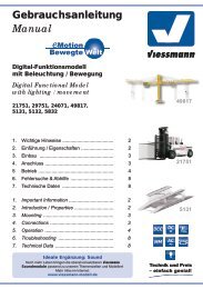
Gebrauchsanleitung<br />
Manual<br />
5104<br />
Bahnschranke mit Behang<br />
vollautomatisch, mit Zubehör<br />
Automatic Crossing Barrier<br />
with accessories<br />
1. Wichtige Hinweise ...................................... 2<br />
2. Einleitung ................................................... 2<br />
3. Inhalt .......................................................... 5<br />
4. Funktionskontrolle ...................................... 5<br />
5. Montage ..................................................... 6<br />
6. Anschluss ................................................... 8<br />
7. Anschluss von Zubehör .............................. 12<br />
8. Digitalbetrieb .................................. 12<br />
9 Montage der Verkehrszeichen .................... 16<br />
10. Technische Daten ...................................... 16<br />
1. Important Information ................................. 2<br />
2. Introduction ................................................ 2<br />
3. Content ...................................................... 5<br />
4. Function Check .......................................... 5<br />
5. Mounting ..................................................... 5<br />
6. Electrical Connections ................................. 7<br />
7. Connecting Accessories.............................. 13<br />
8. Digital Control ............................................ 14<br />
9. Installing Traffic Signs ............................ 16<br />
10. Technical Data ........................................... 16<br />
AC<br />
~<br />
DC =<br />
MM<br />
DCC
2<br />
DE<br />
1. Wichtige Hinweise<br />
Lesen Sie vor der ersten Benutzung des Produktes<br />
bzw. dessen Einbau diese <strong>Anleitung</strong> vollständig<br />
und aufmerksam durch. Bewahren Sie<br />
diese <strong>Anleitung</strong> auf. Sie ist Teil des Produktes.<br />
Richtige Verwendung des Produktes<br />
Das Produkt darf ausschließlich gemäß dieser<br />
<strong>Anleitung</strong> verwendet werden. Dieses Modell ist<br />
bestimmt<br />
• zum Einbau in Modelleisenbahnanlagen<br />
und Dioramen<br />
• zum Anschluss an einen zugelassenen<br />
Modellbahntransformator bzw. an einer<br />
mit einem Transformator betriebenen,<br />
elektrischen Steuerung<br />
• zum Betrieb in trockenen Räumen.<br />
Jeder darüber hinausgehende Gebrauch gilt<br />
als nicht bestimmungsgemäß. Der Hersteller<br />
übernimmt keine Haftung für eventuell daraus<br />
resultierende Schäden.<br />
2. Einleitung<br />
Vorbild<br />
Bahnschranken dienen der Sicherung von Bahnübergängen<br />
und sind nach wie vor in Verwendung.<br />
Früher wurden diese Schranken über Seilzüge<br />
durch den Schrankenwärter fernbedient. Heute<br />
werden sie durch vor Ort montierte Elektromotoren<br />
angetrieben.<br />
Die Bedienung der Schranken erfolgt entweder<br />
durch den Schrankenwärter vor Ort oder auch von<br />
einem etwas weiter entfernten Schrankenposten<br />
bzw. vom Stellwerk. Heute werden Schranken oft<br />
auch aus größerer Entfernung ferngesteuert.<br />
Einige Schranken sind mit einem Behang aus Ketten<br />
oder Gittern ausgestattet, der verhindern soll,<br />
dass die Schrankenbäume unterlaufen oder unterfahren<br />
werden.<br />
In Deutschland und anderen mitteleuropäischen<br />
Ländern haben beschrankte Bahnübergänge<br />
meist ein Läutewerk als zusätzliche akustische<br />
Warneinrichtung. Außerdem werden entsprechende<br />
Verkehrszeichen (Warnbaken, Andreaskreuze)<br />
aufgestellt. Bis einschließlich Epoche 4<br />
wurden zusätzlich Wechselblinkanlagen mir roten<br />
Lampen installiert. Heute werden Lichtsignalanlagen<br />
verwendet, die ähnlich einer Verkehrsampel<br />
Gelb und danach Rot anzeigen (Dauerlicht).<br />
Beim Vorbild gibt es auch heute noch Bahnübergänge<br />
mit Schranken, selbst auf Hauptstre-<br />
EN<br />
1. Important Information<br />
Please read this manual prior to first use of the<br />
product resp. its installation! Keep this manual. It is<br />
part of the product.<br />
Using the product in the right manner<br />
This product may only be used according to the<br />
instructions stated in this manual. This model is<br />
intended for use as follows:<br />
• For installation on model train layouts and<br />
dioramas,<br />
• For connecting it to an approved model<br />
train transformer or a control system powered<br />
by such a transformer<br />
• For operation in dry rooms.<br />
Any other use is not considered to be in accordance<br />
with regulations. The manufacturer is not<br />
liable for any damage that may be caused by inappropriate<br />
use.<br />
2. Introduction<br />
Prototype<br />
Railway crossing barriers serve to provide the necessary<br />
safety at level crossings and are still in use<br />
today. In the past these crossing barriers were operated<br />
via wire pulleys even when the crossing<br />
keeper was located some distance away. Today<br />
they are usually powered by locally installed electric<br />
motors.<br />
Crossing barriers are usually operated by dedicated<br />
personnel located at the level crossing or somewhat<br />
further away from a signal box or switch tower.<br />
Today crossing barriers may also be controlled<br />
from switch towers that are located a long distance<br />
away.<br />
Some crossing barriers are equipped with a curtain<br />
made off chains or wire mesh, which prevents any<br />
vehicle running under the actual barrier.<br />
In Germany and other countries most level crossing<br />
barriers have a signal bell as an additional<br />
acoustic warning system. In addition, specific traffic<br />
signs such as range poles and St. Andrew´s<br />
crosses are placed ahead of the level crossing. In<br />
the past until and including era IV red blinking signal<br />
lights were also installed as an additional warning<br />
for motorists. Today standard traffic signals<br />
similar to those used at road intersections indicating<br />
amber followed by (continuous) red are commonly<br />
installed.<br />
The prototype railways still use barriers at level<br />
crossings today. That is even true for mainlines
cken bis zu einer Höchstgeschwindigkeit von 160<br />
km/h. Allerdings werden es immer weniger, da alle<br />
handbetätigten Bahnübergänge nach und nach<br />
durch moderne Lichtzeichenanlagen oder überhaupt<br />
durch Unter-oder Überführungen ersetztwerden<br />
Modell<br />
Dieses <strong>Viessmann</strong>-Modell einer Bahnschranke<br />
gibt die Vorbildsituation originalgetreu wieder. Die<br />
beiden Schrankenbäume werden durch je einen<br />
Unterflur-Kompaktantrieb angetrieben, welche diese<br />
vorbildgerecht langsam heben und senken. Da<br />
auf vielen Modellbahnanlagen der Platz begrenzt<br />
ist, kann die Geschwindigkeit der Schrankenbewegung<br />
ganz einfach beschleunigt werden. Mehr<br />
Information finden Sie in Abb. 3.<br />
Diese Schranke kann vielseitig eingesetzt und unterschiedlichen<br />
Betriebssituationen angepasst<br />
werden. Übergänge im Winkel von 45°, mehrgleisige<br />
Übergänge oder der Einsatz von vier Schrankenbäumen<br />
als vierschlägige Schranke für sehr<br />
breite Straßen sind kein Problem (die Widerlager<br />
werden zwar mitgeliefert, sind aber für die einwandfreie<br />
Funktion der Schranke nicht notwendig.<br />
Die Schrankenbäume stehen auch ohne Stütze in<br />
der Endlage waagerecht).<br />
Zwei Gleisfüllstücke sowie Rampen, die die Straße<br />
auf das Gleisniveau bringen, liegen bei.<br />
Die beiliegenden Verkehrsschilder sind bereits fertig<br />
bedruckt. Für den Einsatz der Schranke in den<br />
Epochen II - III sind an den Andreaskreuzen und<br />
den Warnbaken Bruchkanten angebracht, um diese,<br />
den damaligen Straßenverkehrsvorschriften<br />
entsprechend, kürzen zu können.<br />
3. Inhalt<br />
Das Schrankenset besteht aus den in der folgenden<br />
Tabelle angeführten Teilen. Bitte prüfen<br />
Sie vor dem Einbau, ob der Verpackungsinhalt<br />
vollständig ist. (Siehe Abb. 1)<br />
Bitte beachten Sie, dass die im Auslieferungszustand<br />
montierten Widerlager nur der Transportsicherung<br />
dienen und dass sie beim Verbau gegen<br />
die im Beipackbeutel liegenden Widerlager ausgetauscht<br />
werden sollten.<br />
with a maximum speed of up to 160 km/h. However,<br />
the number of such manually operated barriers<br />
is decreasing since all manually operated barriers<br />
are being replaced step by step by modern sets of<br />
lights or by over- or underpasses.<br />
Model<br />
The <strong>Viessmann</strong> model of a crossing barrier truly<br />
simulates the prototypical situation and is an eye<br />
catcher on any model train layout. The two barriers<br />
are operated by their own dedicated compact<br />
driving mechanism assuring the prototypical slow<br />
movement of the barriers. Since space is at a premium<br />
on many model train layouts one can increase<br />
the speed of movement of the barriers. You<br />
will find more information on how to accomplish<br />
this in Fig. 3.<br />
The separate drives also provide freedom in using<br />
these barriers in many different situations as they<br />
can easily be adapted to various operating conditions.<br />
Level crossings meeting the tracks diagonally,<br />
multi-track mainlines or installing four barriers<br />
for extra wide roads do not present any problems<br />
(the supports are supplied with this unit but are not<br />
needed since the barriers remain horizontal in the<br />
lower position even without any support).<br />
Both, an infill between the rails as well as ramps<br />
raising the road surface to the track level are included<br />
in the package.<br />
The traffic signs are already printed. For modelling<br />
layouts in eras II – III the St. Andrews crosses and<br />
range poles have to be shortened. For this reason<br />
breaking edges are provided on the St. Andrew’s<br />
crosses and the range poles.<br />
3. Content of the package<br />
This barrier set contains the parts listed in the following<br />
table. Please check the content of the package<br />
regarding completeness prior to installation:<br />
(Fig. 1)<br />
Please also note that the barrier supports installed<br />
in the package only serve as transport lock. Please<br />
use the barrier supports supplied in the package<br />
when installing the barriers.<br />
3
Pos. Bezeichnung / Description Stück<br />
1 Schranke mit Antrieb und Decoder / Barrier with driving mechanism and decoder 1<br />
2 Schranke mit Antrieb / Barrier with driving mechanism 1<br />
3 Verkehrsschild mit Mast / Traffic sign with pole 2<br />
4 Andreaskreuz mit Mast / St.Andrew‘s cross with pole 2<br />
5 Warnbaken mit Mast / Range pole 12<br />
6 Rampe / Ramp 2<br />
7 Rampenfuß / Ramp base 4<br />
8 Gleiszwischenstück / Infill between rails 1<br />
9 Gleiszwischenstück mit Kabel / Infill between rails with wire 1<br />
10 Schrankenbaumwiderlager / Barrier support 2<br />
11 Oberes Sockelstück für Widerlager / Upper base for barrier support 2<br />
12 Unteres Sockelstück für Widerlager / Lower base for barrier support 2<br />
13 Oberes Sockelstück für Schranke / Upper base for barrier 2<br />
14 Unteres Sockelstück für Schranke / Lower base for barrier 2<br />
15 Widerstand 330 Ohm; 0,25 W / Resistor 330 Ohm; 0.25 W 1<br />
Abb. 1<br />
Fig. 1<br />
Abb. 2<br />
Fig. 2<br />
4<br />
Achtung:<br />
Fassen Sie die Schranken<br />
nie am Baum oder<br />
Lager an, sondern nur<br />
an der Bodenplatte bzw.<br />
dem Antriebszylinder!<br />
Attention:<br />
Never touch the barrier<br />
itself. If you have to remove<br />
the model, don’t<br />
pull the model. Carefully<br />
take the drive unit instead<br />
and push it up.<br />
90°
4. Funktionskontrolle<br />
Nehmen Sie die Bahnschranken vorsichtig aus<br />
der Verpackung. Führen Sie vor der Montage eine<br />
Funktionskontrolle durch.<br />
Schließen Sie dazu das gelbe und braune Kabel<br />
an den Wechselspannungsausgang (16 V) eines<br />
Modellbahntransformators – z. B. <strong>Viessmann</strong><br />
5200 – an. Der Trafo muss während des Anschließens<br />
ausgeschaltet sein.<br />
Verbinden Sie abwechselnd jeweils eines der beiden<br />
blauen Kabel mit einem der Wechselspannungsausgänge<br />
des Trafos.<br />
Blau mit roter Markierung:<br />
Schranken werden geöffnet.<br />
Blau mit grüner Markierung:<br />
Schranken werden geschlossen.<br />
4. Function check<br />
Carefully take the barriers out of the packaging.<br />
Check the proper functionality prior to installing the<br />
barriers.<br />
Connect the yellow and the brown wires to the<br />
16V AC output of your transformer – e.g.:<br />
<strong>Viessmann</strong> 5200.<br />
Make sure that the transformer is switched off<br />
while you connect the above mentioned wires!<br />
Then connect alternately one of the two blue wires<br />
with one output terminal of the transformer.<br />
Blue with red sleeve:<br />
Barriers will be raised.<br />
Blue with green sleeve:<br />
Barriers will be lowered<br />
Abb. 3<br />
Fig. 3<br />
schwarz<br />
schwarz<br />
blau<br />
blau<br />
black<br />
black<br />
blue<br />
blue<br />
schwarz: durchtrennen für schnellere Schrankenbewegung<br />
Black: cut this wire for faster barrier movement<br />
blau mit grüner Markierung: Schranke schließen<br />
Blue with green mark: lowering barriers<br />
blau mit roter Markierung: Schranke öffnen<br />
Blue with red mark: raising barriers<br />
orange<br />
grün<br />
braun<br />
gelb<br />
orange<br />
green<br />
brown<br />
yellow<br />
orange: Kontakt für Soundmodul und Blinkelektronik<br />
Orange: connection for sound module and blinking module<br />
grün: gemeinsamer Mittelpunkt für Soundmodul und Blinkelektronik<br />
Green: common wire for sound module and blinking module<br />
braun: Stromversorgung<br />
Brown: power supply<br />
gelb: Stromversorgung<br />
Yellow: power supply<br />
5. Montage<br />
1. Zeichnen Sie die Positionen der Bohrungen für<br />
die Schranken (1) und (2) mit Hilfe des in Abb.<br />
4 abgebildeten Bohrschemas an. Die Mittelpunkte<br />
der Bohrungen müssen einen Abstand<br />
von 73 mm haben.<br />
2. Bohren Sie an den angezeichneten Stellen jeweils<br />
ein Loch mit einem Durchmesser von 13<br />
mm für die Schrankenantriebe.<br />
3. Stecken Sie die Schranken mit dem Antrieb<br />
von oben durch die Bohrungen.<br />
4. Schieben Sie die Befestigungsringe von unten<br />
so auf die Antriebe auf, dass die Rastnasen um<br />
90° zu der Riffelung am Gehäuse der Antriebe<br />
verdreht sind (Abb. 2) und in der Riffelung<br />
des Antriebsgehäuses für einen festen Halt<br />
5. Mounting<br />
1. Mark the positions for drilling the holes for the<br />
driving mechanism (1) and (2) with the aid of<br />
the drawing shown in Fig. 4.The centres of<br />
these holes must be 73mm apart from each<br />
other.<br />
2. Drill a 13mm hole each at the marked positions<br />
through which the drive mechanisms will be inserted.<br />
3. Insert the driving mechanisms from above into<br />
the holes.<br />
4. Push the fixing rings onto the driving mechanisms<br />
from below until their snap tabs sit at an<br />
angle of 90° against the ribbing on the housing<br />
of the mechanism (Fig. 2) and are firmly<br />
arrested. During this process you should hold<br />
5
sorgen. Hierbei sollten Sie die Sockel der<br />
Bahnschranke von oben festhalten.<br />
5. Stecken Sie die Widerlager in die entsprechenden<br />
Bohrungen ein.<br />
6. Kleben Sie das Gleisfüllstück (8) bzw. (9) auf<br />
die Schwellen zwischen den Schienenprofilen<br />
im Bereich des Bahnüberganges auf. Bei<br />
Zweileitergleisen (Roco, Fleischmann,<br />
Trix, Peco, Lima, usw.) verwenden Sie bitte das<br />
Gleiszwischenstück ohne Metallstreifen und<br />
Anschlusskabel.<br />
Für Mittelleitergleise (Märklin C, M und K,<br />
Trix Express) verwenden Sie bitte das Gleiszwischenstück<br />
mit Metallstreifen und rotem Anschlusskabel.<br />
Das rote Anschlusskabel führen Sie<br />
zwischen den Schwellen nach unten (eventuell<br />
zuvor ein Loch bohren) und schließen es am Mittelleiter-Fahrstromanschluss<br />
(rot bei Märklin) an.<br />
Zum Erstellen breiterer oder mehrgleisiger Übergänge<br />
für H0 gibt es unter der Art.-Nr. 5101 (Zweileiter)<br />
und Art.-Nr. 5102 (Mittelleiter) einen Ergänzungssatz<br />
mit jeweils einem entsprechenden<br />
Gleiszwischenstück. Die Rampen (6) dienen als<br />
Auffahrt für die Modellautos auf das Gleisniveau.<br />
Eine der Schranken ist bereits mit der Steuerungsplatine<br />
(Decoder) verbunden. Die andere<br />
Schranke muss man mit Hilfe eines Steckers an<br />
die Platine anschließen. Bitte beachten Sie die<br />
richtige Polarität! Eine inkorrekte Verkabelung<br />
könnte zur Beschädigung führen!<br />
down the base of the barrier form above.<br />
5. Insert the barrier supports into the appropriate<br />
holes.<br />
6. Glue the infill (8) or (9) onto the sleepers between<br />
the rails matching the location of the<br />
ramps. Please use the infill without the metal<br />
strip and wire for two-rail systems (Roco,<br />
Fleischmann, Trix, Peco, Lima, etc.).<br />
Correspondingly use the one with the metal strip<br />
and the red wire for tracks with centre pick-up<br />
(Märklin C, M and K tracks, Trix Express). Install<br />
the red wire by guiding it through a hole between<br />
the sleepers (you may have to drill a hole for this<br />
purpose) and connect it to the centre conductor of<br />
the track (red in case of Märklin).<br />
For realising wider level crossings or over several<br />
tracks you may purchase additional infills, part-No:<br />
5101 (two-rail system) and part-No: 5102 (threerail-system).<br />
The ramps (6) serve to raise the road<br />
to the level of the tracks.<br />
One drive mechanism is already connected to<br />
the control circuit board. The other one has to be<br />
connected by means of the micro plug after installing<br />
the barrier. Please observe the correct polarity!<br />
Incorrect wiring may cause damage to<br />
the product!<br />
Abb. 4<br />
Fig. 4<br />
13 mm<br />
73 mm<br />
Widerlager<br />
Barrier support<br />
Schrankenantrieb<br />
Barrier drive<br />
4 mm<br />
5 mm<br />
5,5 mm<br />
13 mm<br />
Das nebenstehende Symbol kennzeichnet<br />
eine Leitungsverbindung. Die sich hier<br />
kreuzenden Leitungen müssen an einer<br />
beliebigen Stelle ihres Verlaufs elektrisch leitend<br />
miteinander in Verbindung stehen.<br />
The symbol left designates a cable connection.<br />
The cables that cross here must<br />
be in electrical contact with each other at<br />
some point along their length.<br />
6
6. Anschluss<br />
Alle Anschluss- und Montagearbeiten dürfen<br />
nur bei abgeschalteter Betriebsspannung<br />
durchgeführt werden!<br />
Verwenden Sie nur nach VDE /EN-gefertigte<br />
Modellbahntransformatoren!<br />
Sichern Sie die Stromquellen unbedingt so<br />
ab, dass es bei einem Kurzschluss nicht<br />
zum Kabelbrand kommen kann.<br />
Die Betriebsspannung beträgt 16 V ~.<br />
Schließen Sie die Schranken je nach Art des Betriebssystems<br />
und der Ansteuerung gemäß den<br />
Abbildungen 5 bis 12 an. Zur Bedeutung der<br />
Kabelfarben siehe Abb. 3.<br />
Gleichstrombetrieb: Schließen Sie die gelben<br />
Kabel an den Minuspol der Stromversorgung<br />
an. Diese Bahnschranke ist für konventionellen<br />
und digitalen Betrieb ausgelegt. Der integrierte Digitaldecoder<br />
für die Formate DCC und MM (Märklin/Motorola)<br />
ermöglicht auch die Steuerung über<br />
eine geeignete Digitalzentrale (siehe Kapitel 8).<br />
Ansteuerung der Schranken<br />
Es gibt mehrere Möglichkeiten einen zuggesteuerten<br />
Betrieb zu realisieren:<br />
• Mit Schaltkontakten (Reed-Kontakte &<br />
Magnete z. B.: <strong>Viessmann</strong> 6840 & 6841)<br />
• Mit Schaltgleisen<br />
• Mit Gleisbesetztmeldern (analog oder digital;<br />
z.B.: <strong>Viessmann</strong> 5206)<br />
Abb. 5<br />
zum Soundmodul und Andreaskreuz<br />
To the soundmodule and St. Andrew‘s crosses<br />
6. Electrical Connections<br />
Installation and electrical connection may<br />
only be done when the supply voltage is<br />
switched off!<br />
Only use model train transformers manufactured<br />
according to VDE resp. EN standards!<br />
Install fuses for the power supply units to<br />
assure that the cables cannot catch fire in<br />
case of a short circuit.<br />
The operating voltage is 16 V AC.<br />
Wire the barriers subject to the operating system<br />
used according to Fig. 5 to 12. Also refer to Fig.<br />
3 for an explanation of the colour coding of the<br />
wires.<br />
DC operation: Connect the yellow wire to the<br />
“-“(minus) terminal of the power supply unit.<br />
These barriers are suitable for conventional (analogue)<br />
and digital operation. The integral decoder<br />
supports DCC and MM (Märklin/Motorola) and can<br />
be controlled by a suitable digital command station<br />
(refer to chapter 8 – digital operation).<br />
Controlling the barriers<br />
There are several possibilities for controlling these<br />
barriers by the trains:<br />
• With track contacts (Reed contacts & magnets<br />
e.g.: <strong>Viessmann</strong> 6840 & 6841)<br />
• With switching tracks (activated by each<br />
wheel resp. axle)<br />
• With occupancy detectors (analogue or digital;<br />
e.g.: <strong>Viessmann</strong> 5206)<br />
Fig. 5<br />
blau / blue<br />
blau / blue<br />
zu den Schranken<br />
To the barriers<br />
braun / brown<br />
gelb / yellow<br />
rote Markierung<br />
red marker<br />
DIGITAL ZENTRALE<br />
(Nach Programmierung der Adresse)<br />
oder 16 V ~<br />
oder 16 V = (braun ist positiv)<br />
COMMAND STATION<br />
(after programming the address)<br />
or 16 V ~<br />
or 16 V = (brown is positive)<br />
grüne Markierung<br />
green marker<br />
mind. 1 Zuglänge<br />
min. 1 train length<br />
blau (grüne Markierung) / blue (green marker)<br />
mind. 1 Zuglänge<br />
min. 1 train length<br />
öffnen<br />
open<br />
schließen<br />
close<br />
Fahrtrichtung<br />
schließen öffnen<br />
close open<br />
blau (rote Markierung) / blue (red marker)<br />
gelb / yellow<br />
gelb / yellow<br />
braun / brown<br />
16 V ~ /=<br />
braun / brown<br />
7
Ansteuerung mit Schaltkontakten<br />
(Reed):<br />
Diese Schaltung kann gemäß Abbildung 5 realisiert<br />
werden.<br />
Bitte beachten Sie, dass die Kontakte jeweils mindestens<br />
1 Zuglänge vor bzw. nach den Schranken<br />
eingebaut werden müssen. Andernfalls schließen<br />
sich die Schranken eventuell zu spät bzw. öffnen<br />
sich zu früh, während der Zug noch den Bahnübergang<br />
blockiert.<br />
Sofern Sie auf Grund der Platzverhältnisse auf<br />
Ihrer Anlage die Schranken in einer Richtung<br />
schneller und in der anderen langsamer senken<br />
und heben möchten, schließen Sie zusätzlich ein<br />
elektronisches Relais <strong>Viessmann</strong> 5552 gemäß<br />
Automatic control with track (reed)<br />
contacts:<br />
This can be realised as per Fig. 5.<br />
Please note that the pair of reed contacts must be<br />
located at least on train length before resp. behind<br />
the level crossing. Otherwise the barriers might be<br />
lowered too late or would be raised to soon while<br />
the train is still occupying the level crossing.<br />
Should you – due to space restrictions - wish to<br />
lower the barriers faster in one direction of travel<br />
while keeping the low speed for trains in the other<br />
direction simply connect an electronic relay 5552<br />
according to Fig. 6.<br />
Abb. 6<br />
zu den Schranken<br />
To the barriers<br />
zum Soundmodul und Andreaskreuz<br />
To the soundmodule and St. Andrew‘s crosses<br />
schwarz (durchtrennt) / black (cut)<br />
blau / blue<br />
blau / blue<br />
schwarz (durchtrennt)<br />
braun / brown<br />
gelb / yellow<br />
rote Markierung<br />
red marker<br />
/ black (cut)<br />
* optional<br />
<strong>Viessmann</strong><br />
Elektr. Relais 5552<br />
DIGITAL ZENTRALE<br />
(Nach Programmierung der Adresse)<br />
oder 16 V ~<br />
oder 16 V = (braun ist der positive)<br />
COMMAND STATION<br />
(after programming the address)<br />
or 16 V ~<br />
or 16 V = (brown is positive)<br />
grüne Markierung<br />
green marker<br />
Fig. 6<br />
mind. 1 Zuglänge<br />
min. 1 train length<br />
blau (grüne Markierung) / blue (green marker)<br />
mind. 1 Zuglänge<br />
min. 1 train length<br />
* optional<br />
öffnen<br />
open<br />
schließen<br />
close<br />
Fahrtrichtung<br />
schließen öffnen<br />
close open<br />
* optional<br />
blau (rote Markierung) / blue (red marker)<br />
gelb / yellow<br />
gelb / yellow<br />
braun / brown<br />
16 V ~ /=<br />
braun / brown<br />
8<br />
Abbildung 6 an.<br />
Bei zweigleisigem Betrieb ist ebenfalls ein elektronisches<br />
Relais 5552 erforderlich. Dadurch wird erreicht,<br />
dass bei gleichzeitiger Durchfahrt von zwei<br />
entgegenkommenden Zügen die Schranken erst<br />
wieder geöffnet werden, wenn beide Züge den<br />
Bahnübergang verlassen haben.<br />
Das Anschlussschema ist in Abbildung 7 dargestellt.<br />
Abbildung 7 zeigt auch wie mithilfe eines zweiten<br />
Relais 5552 die Bewegungsgeschwindigkeit<br />
der Schranken richtungsabhängig unterschiedlich<br />
schnell gesteuert werden kann. Sofern Sie die<br />
Schranken immer mit der gleichen Geschwindig-<br />
For double track main lines an electronic relay<br />
5552 is also required. This assures that if and<br />
when two trains are passing the level crossing at<br />
the same time the barriers will only be raised once<br />
both trains have vacated the level crossing. The<br />
wiring diagram is shown in Fig. 7.<br />
Fig 7 also shows how one can adjust the speed<br />
of movement of the barriers individually for trains<br />
moving from left to right and vice versa with the aid<br />
of an additional electronic relay 5552. If you wish to<br />
operate the barriers always with the same speed<br />
simply leave out this second relay.<br />
Automatic control of the barriers with<br />
switching tracks (activated by each<br />
wheel resp. axle):
Abb. 7<br />
Fig. 7<br />
öffnen<br />
open<br />
mind. 1 Zuglänge<br />
min. 1 train length<br />
mind. 1 Zuglänge<br />
min. 1 train length<br />
schließen<br />
close<br />
Fahrtrichtung<br />
schließen<br />
close<br />
öffnen<br />
open<br />
Fahrtrichtung<br />
braun<br />
brown<br />
blau<br />
blue<br />
blau (grüne Markierung) / blue (green marker)<br />
blau<br />
blue<br />
braun<br />
brown<br />
braun / brown<br />
braun / brown<br />
* optional<br />
16 V ~<br />
oder<br />
16 V =<br />
(braun ist positiv)<br />
gelb / yellow<br />
braun / brown<br />
blau / blue<br />
gelb / yellow<br />
<strong>Viessmann</strong><br />
Elektr. Relais 5552<br />
blau<br />
blue<br />
blau blue<br />
blau<br />
blue<br />
Elektr. Relais 5552<br />
<strong>Viessmann</strong><br />
blau / blue<br />
blau / blue<br />
For train movements in one direction only<br />
on a single track line you only need to wire<br />
two switching tracks (e.g.: ROCO 61117). The first<br />
switching track on the left in Fig. 8 triggers the<br />
lowering of the barriers. It has to be connected to<br />
the blue cable with the green mark. The second<br />
contact is to be wired to the blue cable with the<br />
red mark and triggers the raising of the barriers.<br />
If the trains on this single track line move<br />
in either direction then the contacts must be<br />
switched from the blue cable with the green mark<br />
to the one with the red mark and vice versa. This<br />
can easily be achieved with an electronic relay<br />
(e.g.: <strong>Viessmann</strong> 5552). (Fig. 9)<br />
A train travelling from left to right first activates the<br />
contact on the far left and sets the directional relay<br />
to the position for this direction. Thus the following<br />
contact on the left is connected via the relay to<br />
the blue cable with the green mark and triggers the<br />
lowering of the barriers as soon as the train reachzum<br />
Soundmodul und Andreaskreuz<br />
To soundmodule and St. Andrew´s crosses<br />
schwarz (durchtrennt) / black (cut)<br />
zu den Schranken<br />
To the barriers<br />
schwarz (durchtrennt) / black (cut)<br />
braun / brown<br />
gelb / yellow<br />
DIGITAL ZENTRALE<br />
oder<br />
16 V ~<br />
oder<br />
16 V = (braun ist positiv)<br />
Nach Programmierung<br />
der Adresse<br />
rot / red Schranke auf COMMAND STATION (after programming<br />
open barrier<br />
or<br />
the address)<br />
16 V ~<br />
grün / green<br />
Schranke zu<br />
close barrier<br />
or<br />
16 V = (brown is positive)<br />
keit betreiben möchten, lassen Sie das zweite Relais<br />
5552 einfach weg.<br />
Ansteuerung mit Schaltgleisen:<br />
Diese kann bei eingleisigem Betrieb in nur<br />
einer Richtung ganz einfach mit zwei Kontakten<br />
realisiert werden. Der erste Kontakt wird mit<br />
dem blauen Kabel mit der grünen Markierung verbunden<br />
und löst die Schließung der Schranken<br />
aus; der zweite nach den Schranken angeordnete<br />
Kontakt wird mit dem blauen Kabel mit der roten<br />
Markierung verbunden und bewirkt das Öffnen der<br />
Schranken (Abb. 8).<br />
Sofern die eingleisige Strecke in beiden<br />
Richtungen befahren wird (Abb 9), muss mittels<br />
eines elektronischen Relais (z.B.: <strong>Viessmann</strong><br />
5552) die Zuordnung der Kontakte angepasst<br />
werden.<br />
Ein von links kommender Zug aktiviert zuerst den<br />
Kontakt ganz links und stellt damit das Richtungs-<br />
9
Abb. 8<br />
Fig. 8<br />
größte Zuglänge<br />
Longest train<br />
größte Zuglänge<br />
Longest train<br />
Schaltgleis / Switching Track<br />
Schaltgleis / Switching Track<br />
Fahrtrichtung<br />
blau (grün Markierung)<br />
blue (green marker)<br />
blau (rote Markierung)<br />
blue (red marker)<br />
braun / brown<br />
braun / brown<br />
schwarz (durchtrennt) / black (cut)<br />
gelb / yellow<br />
braun / brown<br />
gelb / yellow<br />
braun / brown<br />
Decoder 5104<br />
schwarz (durchtrennt) / black (cut)<br />
braun / brown<br />
gelb / yellow<br />
DIGITAL ZENTRALE COMMAND STATION<br />
oder<br />
or<br />
16 V ~<br />
16 V ~<br />
oder<br />
or<br />
16 V = (braun ist positiv) 16 V = (brown is positive)<br />
zu den Schranken<br />
To the barriers<br />
zum Soundmodul und Andreaskreuz<br />
To the soundmodule and the St. Andrew´s crosses<br />
10<br />
relais in die Position für diese Fahrtrichtung. Dadurch<br />
wird der linke Kontakt mit dem blauen Kabel<br />
mit grüner Markierung (Schranke schließen) verbunden.<br />
Sobald der Zug diesen Kontakt erreicht,<br />
werden die Schranken geschlossen.<br />
Nachdem der Zug den Bahnübergang passiert<br />
hat, erreicht er den rechten Kontakt und bewirkt<br />
damit das Öffnen der Schranken. Zuletzt passiert<br />
der Zug den Kontakt ganz rechts, der das Richtungsrelais<br />
wieder für die Gegenrichtung stellt.<br />
Es ist gleichgültig aus welcher Richtung der nächste<br />
Zug kommt, da er immer zuerst einen Kontakt<br />
erreicht, der über das Relais 5552 den in Fahrtrichtung<br />
ersten markierten Kontakt auf den Anschluss<br />
für Schließen und den zweiten auf den<br />
Anschluss für Öffnen schaltet.<br />
Die Ansteuerung der Schranken kann bei einer<br />
zweigleisigen Strecke, wo jedes Gleis in<br />
nur einer Richtung befahren wird, mit zwei<br />
Kontaktgleisen pro Schienenstrang realisiert werden.<br />
Die Kontakte für das Öffnen der Schranken<br />
(also die, die an das blaue Kabel mit der roten<br />
Markierung angeschlossen werden) müssen über<br />
die in Reihe geschalteten Kontakte beider Relais<br />
(z.B.: <strong>Viessmann</strong> 5552) angeschlossen werden.<br />
Damit wird sichergestellt, dass die Schranken nur<br />
dann geöffnet werden, wenn bei sich kreuzenden<br />
es this contact.<br />
After the train has passed the level crossing and<br />
reached the first contact after the barriers, which is<br />
connected via the relay to the blue cable with the<br />
red mark, then it triggers the raising of the barriers.<br />
Finally the train will reach the contact on the far<br />
right that switches the directional relay back in to<br />
the position for the opposite direction of train movement.<br />
It is immaterial from which side the following train<br />
arrives since it will always first pass the contact setting<br />
the directional relay and thus the contacts for<br />
lowering and raising the barriers in the appropriate<br />
sequence.<br />
Automatic control of the barriers on a double<br />
track main line with trains travelling only<br />
in one direction on each track can be<br />
realised with two contacts per track. The contacts<br />
for raising the barriers (the ones connected to the<br />
blue cable with the red marker) must be wired in<br />
series through the appropriate contacts of the directional<br />
relay (e.g.: <strong>Viessmann</strong> 5552). This assures<br />
that the barriers can only be raised when<br />
opposing trains have both vacated the level crossing.<br />
The correct wiring of the decoder 5104 for the barriers<br />
is shown in per Fig. 7 except for substituting
Abb. 9<br />
größte Zuglänge<br />
größte Zuglänge<br />
größte Zuglänge<br />
größte Zuglänge<br />
Longest train Longest train Longest train Longest train<br />
Schaltgleis / Switching Track<br />
schließen<br />
close<br />
Schaltgleis / Switching Track<br />
Fig. 9<br />
DIGITAL ZENTRA<br />
oder<br />
16 V ~<br />
oder<br />
16 V = (braun ist po<br />
COMMAND STAT<br />
or<br />
16 V ~<br />
or<br />
16 V = (brown is po<br />
Fahrtrichtung<br />
schwarz / black<br />
braun / brown<br />
gelb / yellow<br />
blau (rote Markierung) / blue (red marker)<br />
blau (grün Markierung) / blue (green marker)<br />
braun / brown<br />
gelb / yellow<br />
Decoder 5104<br />
blau (grün Markierung) / blue (green marker)<br />
schwarz / black<br />
blau (rote Markierung) / blue (red marker)<br />
16 V<br />
Lichttransformator 5200<br />
Primär<br />
Sekundär 10 V<br />
230 V~<br />
0-10-16 V~<br />
Primär 230 V 50 - 60 Hz<br />
Sekundär 52 VA max. 3,25 A<br />
IP 40 ta 25°C<br />
0 V<br />
Nur für trockene Räume<br />
Gefertigt nach<br />
VDE 0570<br />
EN 61558<br />
schwarz / black<br />
gelb / yellow<br />
schwarz / black<br />
Elektr. Relais 5552<br />
<strong>Viessmann</strong><br />
blau (grün Markierung) / blue (green marker)<br />
schwarz / black<br />
blau (rote Markierung) / blue (red marker)<br />
schwarz / black<br />
Zügen auch der zweite Zug den Bahnübergang<br />
bereits verlassen hat.<br />
Schließen Sie den Schrankendecoder gemäß Abbildung<br />
7 an, wobei Sie anstelle der Reed-Kontakte<br />
ein Schaltgleis verwenden.<br />
Bitte beachten Sie, dass in Abbildung 7 auch<br />
das zweite Relais 5552 für die fahrtrichtungsabhängig<br />
unterschiedliche Geschwindigkeit der<br />
Schranken eingetragen ist. Sofern Sie die Schranken<br />
immer mit der gleichen Geschwindigkeit betreiben<br />
wollen, lassen Sie dieses Relais einfach<br />
weg.<br />
Ansteuerung über Gleisbesetztmelder:<br />
Die Bahnschranken können sowohl im Analogbetrieb<br />
als auch im Digitalbetrieb mit Gleisbesetztmeldern<br />
(z.B.: <strong>Viessmann</strong> 5206) angesteuert werden.<br />
Eine Schaltungsvariante für eine eingleisige<br />
Strecke ist in Abb. 10 dargestellt. Diese Schaltung<br />
gilt sinngemäß auch für eine mehrgleisige<br />
Strecke wobei das blaue Kabel mit der grünen<br />
Markierung mit allen relevanten Kontakten des<br />
Gleisbesetztmelders verbunden werden muss. Da<br />
die Schließfunktion dieser Schranke immer Priorität<br />
hat, wird ein unbeabsichtigtes Öffnen der<br />
Schranken automatisch verhindert solange sich<br />
ein Zug im Bereich des Bahnübergangs befindet.<br />
the reed contacts with the switching track.<br />
Please note that the second relay for changing the<br />
speed of lowering the barrier is also shown in Fig.<br />
7. If you wish to move the barriers always with the<br />
same speed simply leave out this second relay.<br />
Automatic control of the barriers with<br />
track occupancy detectors:<br />
The barriers may be controlled with track occupancy<br />
detectors (e.g.: <strong>Viessmann</strong> 5206) both in<br />
analogue mode and digital mode. The schematic<br />
shown in Fig. 10 for a single track line serves as<br />
an example. In principle this is also applicable for<br />
a double track line. Just bear in mind that the blue<br />
wire with the green marker must be connected to<br />
all appropriate contacts of the occupancy detector.<br />
Since the command “lower the barriers” always<br />
has priority, unintentional raising of the barriers is<br />
automatically prevented.<br />
7. Connecting Accessories<br />
Sound module for a signal bell<br />
The decoder of the barrier is suitable for connecting<br />
a sound module for a signal bell. How to wire<br />
the <strong>Viessmann</strong> sound module 5556 is shown in<br />
Fig. 11.<br />
11
Abb. 10<br />
Öffnen / Open Schließen / Close Öffnen / Open<br />
zu den Schranken<br />
To the barriers<br />
zum Soundmodul und Andreaskreuz<br />
To the soundmodule and St. Andrew‘s Crosses<br />
schwarz / black<br />
blau / blue<br />
blau / blue<br />
schwarz / black<br />
braun / brown<br />
gelb / yellow<br />
rote Markierung<br />
grüne Markierung<br />
* DIGITAL ZENTRALE<br />
* COMMAND STATION<br />
braun / brown<br />
Fig. 10<br />
blau / blue<br />
blau / blue<br />
mind. 1 Zuglänge<br />
min. 1 train length<br />
mind. 1 Zuglänge<br />
min. 1 train length<br />
Fahrtrichtung<br />
mind. 1 Zuglänge<br />
min. 1 train length<br />
mind. 1 Zuglänge<br />
min. 1 train length<br />
rot / red<br />
gelb / yellow<br />
rot / red<br />
braun / brown<br />
16 V ~ /=<br />
braun / brown<br />
rot / red<br />
rot / red<br />
┴<br />
Fahrstrom<br />
bn ge 1 2 3 4 5 6 7 8<br />
16 V ~<br />
<strong>Viessmann</strong><br />
Gleisbesetztmelder<br />
8-fach 5206<br />
*DIGITAL ZENTRALE<br />
(Nach Programmierung der Adresse)<br />
oder 16 V ~<br />
oder 16 V = (braun ist der positive)<br />
*COMMAND STATION<br />
(after programming the address)<br />
or 16 V ~<br />
or 16 V = (brown is positive)<br />
blau / blue<br />
blau / blue<br />
12<br />
7. Anschluss von Zubehör<br />
Soundmodul für Läutewerk<br />
Der Schrankendecoder ist bereits für den Anschluss<br />
eines Soundmoduls für das Läutewerk<br />
vorbereitet.<br />
Der Anschluss des <strong>Viessmann</strong> Soundmoduls<br />
5556 ist in Abbildung 11 dargestellt.<br />
Blinklicht für beleuchtete<br />
Andreaskreuze<br />
Der Schrankendecoder hat keine Anschlüsse für<br />
weiteres Zubehör. Allerdings kann das Blinkmodul<br />
5065 für die Andreaskreuze parallel zum Soundmodul<br />
angeschlossen werden.<br />
Bitte beachten Sie, dass das grüne Kabel über ei-<br />
Blinking lights for the St. Andrew´s<br />
crosses<br />
The decoder of the barrier does not have any<br />
other terminals for additional accessories besides<br />
the sound module. However, you may connect<br />
the blinking module 5065 for the warning<br />
lights of the St. Andrew´s crosses in parallel to<br />
the sound module.<br />
Please note that the green wire must be connected<br />
via a 330 Ohm/0.25 Watt resistor to the<br />
blinking module.<br />
In digital mode the warning lights can also be<br />
operated with a digital switching decoder and a<br />
blinking module.<br />
For more information please refer to chapter 8<br />
(Digital operation).
Primär<br />
230 V~<br />
Commander<br />
16 V<br />
Sekundär 10 V<br />
0-10-16 V~<br />
Primär 230 V 50 - 60 Hz<br />
Sekundär 52 VA max. 3,25 A<br />
IP 40 ta 25°C<br />
0 V<br />
Nur für trockene Räume<br />
Gefertigt nach<br />
VDE 0570<br />
EN 61558<br />
nen Widerstand mit 330 Ohm mit einer Leistung<br />
von 0,25 Watt angeschlossen werden muss.<br />
Die Warnlichter der Andreaskreuze können im Digitalbetrieb<br />
auch über einen Schaltdecoder und<br />
eine Blinklichtelektronik gesteuert werden.<br />
Abb. 11<br />
8. Digital Operation<br />
These barriers are suitable for conventional<br />
(analogue) and digital operation.<br />
The integral decoder supports the DCC and the<br />
Fig. 11<br />
braun / brown<br />
Lichttransformator 5200<br />
Decoder 5104<br />
gelb / yellow<br />
braun / brown<br />
gelb / yellow<br />
E<br />
rt<br />
z. B. 5200<br />
e. g. 5200<br />
zu den Decodern<br />
bn<br />
viessmann<br />
Powermodul 5215<br />
Braune Massebuchsen<br />
nicht koppeln !<br />
ge max. 24 V~ bn<br />
Positive<br />
T<br />
gelb / yellow<br />
braun / brown<br />
grün / green<br />
orange / orange<br />
blau / blue<br />
Geschwindigkeit:<br />
Originalstand: 6 sec<br />
nach dem Schnitt: 3 sec<br />
Barrier speed:<br />
Original:<br />
6 sec<br />
After cutting the wire: 3 sec<br />
5215<br />
5215<br />
blau / blue<br />
blau / blue<br />
orange / orange<br />
grün / green<br />
grün<br />
green<br />
330Ohm<br />
0,25W<br />
orange<br />
orange<br />
rote Markierung<br />
red marker<br />
grüne Markierung<br />
green marker<br />
z. B. Commander<br />
e. g. Commander<br />
Synchronausgang<br />
Synchroneingang<br />
viessmann<br />
Soundmodul 5556<br />
bn 16 V ~ ge<br />
viessmann<br />
4-fach-Blinkgerät 5065<br />
Universal Tasten - Stellpult<br />
DIGITAL ZENTRALE<br />
(Nach Programmierung der Adresse)<br />
oder 16 V ~<br />
oder 16 V = (braun ist der positive)<br />
COMMAND STATION<br />
(after programming the address)<br />
or 16 V ~<br />
or 16 V = (brown is positive)<br />
gelb / yellow<br />
braun / brown<br />
14-16V<br />
~ / =<br />
intern / extern<br />
1<br />
2<br />
zu den Andreaskreuzen<br />
To the St. Andrews crosses<br />
ge<br />
3<br />
4<br />
braun<br />
brown<br />
<strong>Viessmann</strong><br />
5547<br />
Näheres finden Sie im Kapitel 8 (Digitalbetrieb).<br />
8. Digitalbetrieb<br />
Diese Bahnschranke ist für konventionellen und<br />
digitalen Betrieb ausgelegt.<br />
Der integrierte Digitaldecoder unterstützt die<br />
Formate DCC und MM (Märklin/Motorola) und ermöglicht<br />
die Steuerung über eine geeignete Digitalzentrale<br />
(z. B.: <strong>Viessmann</strong> Commander).<br />
Der Decoder empfängt die Digitalbefehle über<br />
die Versorgungsleitungen während die Steuerleitungen<br />
für den zusätzlichen zuggesteuerten Automatikbetrieb<br />
verwendet werden können. Ab Werk<br />
ist der Decoder auf die Digitaladresse 1 (DCC)<br />
eingestellt.<br />
Adressvergabe:<br />
Zur digitalen Steuerung des Funktionsmodells<br />
müssen Sie diesem zunächst eine Digitaladresse<br />
zuteilen:<br />
1. Schalten Sie den Ausgang des Digitalsystems<br />
aus. Es darf keine Spannung am Schrankendecoder<br />
anliegen.<br />
MM (Märklin/Motorola) data formats and it can be<br />
controlled by a suitable digital command station<br />
(e.g.: <strong>Viessmann</strong> Commander).<br />
The decoder receives the digital commands via<br />
the power supply cables. The blue control wires<br />
may be used for controlling the barriers automatically<br />
by the trains. The decoder default address<br />
in DCC mode is 1.<br />
Assigning an address:<br />
For digital control of this model you must first assign<br />
a digital address.<br />
Now the model is ready for operation with the<br />
newly assigned address. Should you wish to<br />
change the address at a later stage simply repeat<br />
this procedure.<br />
1. Turn off the output of the digital system. Make<br />
sure the decoder of the barriers is not connected<br />
to any voltage at all.<br />
2. Then connect the power supply cables (yellow<br />
and brown) to the track or directly to the command<br />
station.<br />
3. Connect the two blue control cables to one<br />
track each of the corresponding terminals of<br />
the command station; in other words one blue<br />
13
2. Verbinden Sie die Stromversorgungsleitungen<br />
(gelb und braun) mit dem Gleis oder direkt mit<br />
der Zentrale.<br />
3. Verbinden Sie beide Steuerleitungen mit je<br />
einem Gleis oder den entsprechenden Anschlüssen<br />
an der Zentrale, also eines der blauen<br />
Kabel an ein Gleis, das andere blaue Kabel<br />
an das andere Gleis bzw. den Mittelleiter.<br />
4. Schalten Sie die Digitalspannung ein und<br />
warten sie mindestens eine Sekunde.<br />
5. Nun entfernen Sie je nach Digitalsystem eine<br />
der beiden Steuerleitungen (bei DCC bleibt das<br />
blaue Kabel mit der roten Markierung am Gleis;<br />
bei MM das blaue Kabel mit der grünen Markierung).<br />
6. Senden Sie nun mit der Digitalzentrale einen<br />
Schaltbefehl an die gewünschte Adresse. Der<br />
Schrankendecoder empfängt den Befehl, registriert<br />
die Adresse im gewünschten Datenformat<br />
und quittiert diese durch Bewegung der<br />
Schranken, sofern die aktuelle Stellung der<br />
Schranken dies zulässt.<br />
Falls sich die Schranken nicht bewegt haben<br />
weil sie ohnehin schon in der dem Schaltbefehl<br />
entsprechenden Stellung waren, geben Sie einfach<br />
den zweiten Befehl (also wenn Sie vorher<br />
den Befehl „Schließen“ gegeben haben, aktivieren<br />
Sie nun „Öffnen“). Damit bewegen sich<br />
nun die Schranken zur Bestätigung.<br />
7. Jetzt können Sie die Steuerleitung wieder entfernen.<br />
Im Digitalbetrieb werden nur die beiden<br />
cable goes to one track and the other one to<br />
the other track or the centre conductor of a<br />
three-rail system.<br />
4. Turn on the digital voltage and wait for at least<br />
one second.<br />
5. Now remove one of the two control wires. This<br />
is subject to the type of command station. In<br />
DCC mode the blue cable with the red marker<br />
remains connected to the track; when using an<br />
MM command station the blue cable with the<br />
green marker remains connected.<br />
6. Transmit a command with your command station<br />
to the desired address. The barrier decoder<br />
receives this signal and registers the address<br />
in the desired data format and confirms<br />
receipt of this command by moving the barriers.<br />
Since this is subject to the current status of the<br />
barriers (raised or lowered) the barriers may<br />
not move because they are already in the position<br />
for which the command was given. In that<br />
case simply issue the other command (lowering<br />
if the barriers are raised or raising them, if they<br />
are lowered already). Then the barriers will<br />
move to indicate confirmation.<br />
7. Now you may remove the blue control wires<br />
again. For pure digital operation only the two<br />
power supply wires (yellow and brown) are<br />
needed. The blue control wires are available<br />
for analogue control by trains via reed contacts,<br />
switching tracks or occupancy detectors.<br />
Abb. 12<br />
Fig. 12<br />
Digitalsteuerung der Bahnschranke und Andreaskreuz-Elektronik.<br />
Digital control of barriers and blinking module for St. Andrew´s crosses<br />
DIGITAL ZENTRALE<br />
oder 16 V ~<br />
oder 16 V = (braun ist der positive)<br />
gelb / yellow<br />
braun / brown<br />
Digitalzentrale<br />
Command station<br />
z.B. 5200<br />
COMMAND STATION<br />
or 16 V ~<br />
or 16 V = (brown is positive)<br />
Blinkgerät<br />
Blinking module<br />
Schaltdekoder<br />
Switching decoder<br />
z.B. 5213, 5209<br />
bn 16 V ~ ge<br />
viessmann<br />
4-fach-Blinkgerät 5065<br />
Commander<br />
1<br />
2<br />
ge<br />
3<br />
4<br />
zu Andreaskreuzen<br />
To the St. Andrew’s crosses<br />
rot / red<br />
braun / brown<br />
braun / brown<br />
braun / brown<br />
gelb / yellow<br />
braun<br />
zu den Schranken / To the barriers<br />
14<br />
zu den Schranken / To the barriers
Stromversorgungsleitungen (gelb und braun)<br />
benötigt. Die beiden Steuerleitungen stehen<br />
nun für die analoge Ansteuerung durch die<br />
Züge über Kontakte oder Gleisbesetztmelder<br />
zur Verfügung.<br />
Damit ist das Modell unter der neuen Adresse betriebsbereit.<br />
Falls Sie die Adresse künftig ändern<br />
möchten, wiederholen Sie einfach diesen Vorgang.<br />
Anschluss der Blinklichter für<br />
beleuchtete Andreaskreuze<br />
Der Schrankendecoder hat keine Anschlüsse für<br />
weiteres Zubehör. Allerdings kann die Blinkelektronik<br />
5065 für die Andreaskreuze parallel zum<br />
Soundmodul 5556 gemäß Abb. 11 angeschlossen<br />
werden.<br />
Die Blinklichter können im Digitalbetrieb aber<br />
auch gemäß Abbildung 12 über einen Ausgang<br />
eines Schaltdecoders (z.B.: <strong>Viessmann</strong> 5213 für<br />
MM oder 5209 für DCC) und die Blinkelektronik<br />
(<strong>Viessmann</strong> 5065) gesteuert werden.<br />
Bitte beachten Sie, dass der Schaltdecoder 5213<br />
bzw. 5209 sinnvollerweise die gleiche Adresse erhalten<br />
sollte wie der Schrankendecoder. So werden<br />
die Blinklichter und die Schranken mit einem<br />
Digitalbefehl aktiviert.<br />
Sofern Schranke und Schaltdecoder unterschiedliche<br />
Adressen haben, dann muss man entweder<br />
2 separate Schaltbefehle geben oder die Decoder<br />
z.B. über eine Fahrstraßenschaltung automatisch<br />
aktivieren.<br />
Dadurch lassen sich die Blinklichter zum Beispiel<br />
kurz vor der Schranke einschalten.<br />
Abb. 13<br />
4 mm<br />
4<br />
Now the model is ready for operation with the<br />
newly assigned address. Should you wish to<br />
change the address at a later stage simple repeat<br />
this procedure.<br />
Connecting the blinking lights for illuminated<br />
St. Andrew´s crosses<br />
The barrier decoder does not have any terminals<br />
for further accessories. However, you may<br />
connect a blinking module 5065 for the St. Andrew’s<br />
crosses in parallel to the sound module<br />
as shown in Fig. 11. Please note that you have<br />
to connect a 330 Ohm resistor (0.25 Watt) to the<br />
green wire leading to the blinking module.<br />
In digital mode the blinking lights can also be<br />
wired to the output of a switching decoder (e.g.:<br />
<strong>Viessmann</strong> 5213 for MM or 5209 for DCC) and<br />
the blinking module (<strong>Viessmann</strong> 5065) as shown<br />
in Fig. 12.<br />
Please note that the switching decoder 5213<br />
resp. 5209 should have the same address as the<br />
barrier decoder. Thus the blinking lights as well<br />
as the barrier will be activated with one single<br />
command.<br />
Should the barriers and the switching decoder<br />
be assigned different addresses then one<br />
must either transmit two separate commands or<br />
switch the decoders automatically for instance<br />
via route control.<br />
This has the advantage that the lights can be<br />
turned on shortly before the barriers.<br />
zum Bahnübergang<br />
to the railroad crossing<br />
5 5<br />
5<br />
Fig. 13<br />
3<br />
9. Montage der Verkehrsschilder<br />
1. Für die Verwendung der Schilder in den Epochen<br />
II und III kürzen Sie zunächst die Warnbaken<br />
(5) und die Andreaskreuze (4) an den vorgegebenen<br />
Bruchkanten auf der Rückseite der<br />
Schilder. Evtl. mit scharfem Messer vorritzen!<br />
2. Kleben Sie die Andreaskreuze und auch die<br />
Warnbaken mit handelsüblichem Polystyrol-<br />
Kleber an die entsprechenden Masten.<br />
Beachten Sie hierbei, dass in den Epochen II<br />
und III das Andreaskreuz (4) um 90° gedreht<br />
am Mast befestigt wurde, wobei die kurzen<br />
9. Installing the traffic signs<br />
1. To use the signs in periods II and III, first shorten<br />
the warning sign (3) and the St. Andrew’s<br />
crosses (4) at the specified breaking edges on<br />
the rear of the signs. If necessary, first cut an<br />
indentation with a sharp knife!<br />
2. Glue the St. Andrew’s crosses with standard<br />
polystyrene glue to their respective poles.<br />
Please note that in periods II and III the St.<br />
Andrew’s cross (4) was mounted at a 90° angle<br />
on the pole, with the short shanks pointing<br />
downwards.<br />
15
Schenkel nach unten zeigten.<br />
3. Bohren Sie an den dafür vorgesehenen Stellen<br />
Löcher mit 4mm Durchmesser und montieren<br />
Sie die Schilder in der richtigen Reihenfolge (siehe<br />
Abb. 13).<br />
4. Der Regelabstand zwischen den Warnbaken<br />
beträgt beim Vorbild 80 m, das entspricht in<br />
H0 etwa 92 cm. Wenn die örtli-chen Gegebenheiten<br />
es erfordern, sind aber auch kürzere Abstände<br />
erlaubt.<br />
5. Bei beengten Platzverhältnissen können Sie die<br />
Warnbaken (5) mit den drei Streifen mit einem<br />
Messer vom eigenen Mast abtrennen und unten<br />
an den Mast des Verkehrszeichens (3) kleben.<br />
3. Drill 4mm holes as shown in Fig. 7 at the positions<br />
desired and install the signs in the correct<br />
sequence (see Figure 13).<br />
4. The regular spacing between the prototype<br />
warning signs resp. range poles is 80 m; that<br />
corresponds with about 92 cm in H0. If local<br />
conditions were somewhat tight then the range<br />
poles (5) would be spaced at shorter distances.<br />
5. As an additional measure the range pole (5)<br />
with the three strips may be separated from its<br />
pole and glued onto the pole of the first warning<br />
sign (3).<br />
10. Technische Daten<br />
Datenformat: analog (AC, DC), digital (DCC,<br />
MM)<br />
Betriebsspannung: 16 V<br />
Betriebsstrom: < 150 mA<br />
Ruhestrom: < 30 mA<br />
10. Technical Data<br />
Data formats: analogue (AC, DC), digital<br />
(DCC, MM)<br />
Operating voltage: 16 V<br />
Operating current: < 150 mA<br />
Stand-by current: < 30 mA<br />
Modellbauartikel, kein Spielzeug! Nicht geeignet für Kinder unter<br />
14 Jahren! Die Anschlussdrähte niemals in eine Steckdose einführen!<br />
<strong>Anleitung</strong> aufbewahren!<br />
Model building item, not a toy! Not suitable for children under 14<br />
years! Never put the connecting wires into a power socket! Keep<br />
these instructions!<br />
Ceci n’est pas un jouet. Ne convient pas aux enfants de moins de<br />
14 ans ! Ne jamais introduire les fils d’alimentation dans une prise!<br />
Conservez ce mode d’emploi !<br />
Modelbouwartikel, geen speelgoed! Niet geschikt voor kinderen<br />
onder 14 jaar! De aansluitdraden nooit in een wandcontactdoos steken!<br />
Gebruiksaanwijzing bewaren!<br />
Articolo di modellismo, non è un giocattolo! Non adatto a bambini<br />
al di sotto dei 14 anni! Non inserire mai i fili di collegamento in una<br />
presa! Conservare instruzioni per l’uso!<br />
Artículo para modelismo ¡No es un juguete! No recomendado para<br />
menores de 14 años! ¡No introducir nunca los hilos de conexiones en<br />
un enchufe de la red eléctrica! Conserva las instrucciones de servicio!<br />
<strong>Modellspielwaren</strong> <strong>GmbH</strong><br />
87406<br />
Stand 01<br />
12/2012<br />
HO