Anleitung - Viessmann Modellspielwaren GmbH
Anleitung - Viessmann Modellspielwaren GmbH
Anleitung - Viessmann Modellspielwaren GmbH

Erfolgreiche ePaper selbst erstellen
Machen Sie aus Ihren PDF Publikationen ein blätterbares Flipbook mit unserer einzigartigen Google optimierten e-Paper Software.
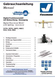
6. Anschluss<br />
Alle Anschluss- und Montagearbeiten dürfen<br />
nur bei abgeschalteter Betriebsspannung<br />
durchgeführt werden!<br />
Verwenden Sie nur nach VDE /EN-gefertigte<br />
Modellbahntransformatoren!<br />
Sichern Sie die Stromquellen unbedingt so<br />
ab, dass es bei einem Kurzschluss nicht<br />
zum Kabelbrand kommen kann.<br />
Die Betriebsspannung beträgt 16 V ~.<br />
Schließen Sie die Schranken je nach Art des Betriebssystems<br />
und der Ansteuerung gemäß den<br />
Abbildungen 5 bis 12 an. Zur Bedeutung der<br />
Kabelfarben siehe Abb. 3.<br />
Gleichstrombetrieb: Schließen Sie die gelben<br />
Kabel an den Minuspol der Stromversorgung<br />
an. Diese Bahnschranke ist für konventionellen<br />
und digitalen Betrieb ausgelegt. Der integrierte Digitaldecoder<br />
für die Formate DCC und MM (Märklin/Motorola)<br />
ermöglicht auch die Steuerung über<br />
eine geeignete Digitalzentrale (siehe Kapitel 8).<br />
Ansteuerung der Schranken<br />
Es gibt mehrere Möglichkeiten einen zuggesteuerten<br />
Betrieb zu realisieren:<br />
• Mit Schaltkontakten (Reed-Kontakte &<br />
Magnete z. B.: <strong>Viessmann</strong> 6840 & 6841)<br />
• Mit Schaltgleisen<br />
• Mit Gleisbesetztmeldern (analog oder digital;<br />
z.B.: <strong>Viessmann</strong> 5206)<br />
Abb. 5<br />
zum Soundmodul und Andreaskreuz<br />
To the soundmodule and St. Andrew‘s crosses<br />
6. Electrical Connections<br />
Installation and electrical connection may<br />
only be done when the supply voltage is<br />
switched off!<br />
Only use model train transformers manufactured<br />
according to VDE resp. EN standards!<br />
Install fuses for the power supply units to<br />
assure that the cables cannot catch fire in<br />
case of a short circuit.<br />
The operating voltage is 16 V AC.<br />
Wire the barriers subject to the operating system<br />
used according to Fig. 5 to 12. Also refer to Fig.<br />
3 for an explanation of the colour coding of the<br />
wires.<br />
DC operation: Connect the yellow wire to the<br />
“-“(minus) terminal of the power supply unit.<br />
These barriers are suitable for conventional (analogue)<br />
and digital operation. The integral decoder<br />
supports DCC and MM (Märklin/Motorola) and can<br />
be controlled by a suitable digital command station<br />
(refer to chapter 8 – digital operation).<br />
Controlling the barriers<br />
There are several possibilities for controlling these<br />
barriers by the trains:<br />
• With track contacts (Reed contacts & magnets<br />
e.g.: <strong>Viessmann</strong> 6840 & 6841)<br />
• With switching tracks (activated by each<br />
wheel resp. axle)<br />
• With occupancy detectors (analogue or digital;<br />
e.g.: <strong>Viessmann</strong> 5206)<br />
Fig. 5<br />
blau / blue<br />
blau / blue<br />
zu den Schranken<br />
To the barriers<br />
braun / brown<br />
gelb / yellow<br />
rote Markierung<br />
red marker<br />
DIGITAL ZENTRALE<br />
(Nach Programmierung der Adresse)<br />
oder 16 V ~<br />
oder 16 V = (braun ist positiv)<br />
COMMAND STATION<br />
(after programming the address)<br />
or 16 V ~<br />
or 16 V = (brown is positive)<br />
grüne Markierung<br />
green marker<br />
mind. 1 Zuglänge<br />
min. 1 train length<br />
blau (grüne Markierung) / blue (green marker)<br />
mind. 1 Zuglänge<br />
min. 1 train length<br />
öffnen<br />
open<br />
schließen<br />
close<br />
Fahrtrichtung<br />
schließen öffnen<br />
close open<br />
blau (rote Markierung) / blue (red marker)<br />
gelb / yellow<br />
gelb / yellow<br />
braun / brown<br />
16 V ~ /=<br />
braun / brown<br />
7