Erfolgreiche ePaper selbst erstellen
Machen Sie aus Ihren PDF Publikationen ein blätterbares Flipbook mit unserer einzigartigen Google optimierten e-Paper Software.
unterer Flügel senkrecht;<br />
Blau mit grüner Markierung:<br />
Signal auf „Fahrt“ (Hp1), oberer Flügel schräg<br />
nach oben, unterer Flügel senkrecht;<br />
Blau mit gelber Markierung:<br />
Signal auf „Langsamfahrt“ (Hp2), beide Flügel<br />
schräg nach oben.<br />
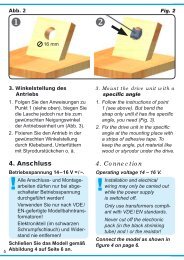
5. Montage<br />
1. Beschriften Sie das Signal (siehe Kapitel 3).<br />
2. Sägen Sie an der Montagestelle ein Loch mit<br />
den Maßen 30 mm x 15 mm. Bohren Sie dazu<br />
zuerst 4 Löcher mit 6 mm Durchmesser. Verwenden<br />
Sie die in der Abbildung 3 abgedruckte<br />
Schablone.<br />
3. Führen Sie die Anschlusskabel von oben durch<br />
das Montageloch und stecken Sie dann das Signal<br />
mit dem Antrieb voran hinein.<br />
4. Befestigen Sie das Signal mit den beiliegenden<br />
Schrauben.<br />
6. Anschluss<br />
Alle Anschluss- und Montagearbeiten dürfen<br />
nur bei abgeschalteter Betriebsspannung<br />
durchgeführt werden!<br />
Verwenden Sie nur nach VDE /EN-gefertigte<br />
Modellbahntransformatoren!<br />
Sichern Sie die Stromquellen unbedingt so<br />
ab, dass es bei einem Kurzschluss nicht<br />
zum Kabelbrand kommen kann.<br />
Die Betriebsspannung beträgt 16 V = / ~.<br />
Schließen Sie nun das Signal gemäß den Abbildungen<br />
5 oder 7 an. Zur Bedeutung der Kabelfarben<br />
siehe Abbildung 4.<br />
Für die Versorgung der Signalbeleuchtung empfehlen<br />
wir einen separaten Transformator. Das<br />
5. Mounting<br />
1) Check that the signal works properly as per the<br />
instructions above before you start installing it<br />
on the layout.<br />
2) Letter the signal in accordance with the instructions<br />
on page 3.<br />
3) Saw a square hole of 30 mm x 15 mm at the<br />
mounting place. But before 4 holes of 6 mm diameter<br />
each should be drilled in the corners.<br />
Use the pattern which is shown in figure 3.<br />
4) The signal‘s connection wires have to be inserted<br />
into the hole first. After that put the signal<br />
with the drive first into that hole.<br />
5) Attach the signal to the baseboard with the enclosed<br />
screws.<br />
6. Connections<br />
Make sure that the power supply is switched<br />
off when you mount the device and connect<br />
the wires!<br />
Only use VDE/EN tested special model train<br />
transformers for the power supply!<br />
The power sources must be protected to prevent<br />
the risk of burning wires.<br />
The operating voltage is 16 V (AC/DC).<br />
Now make the electrical connection as per figure<br />
5 or 7. For the meaning of the cable colours refer<br />
to figure 4<br />
As a supply for the signal light, we recommend a<br />
separate transformer. This will prevent flickering of<br />
the lights due to high consumption of the drive.<br />
Connect the signal light to the transformer via the<br />
yellow cable with black marking and the brown cable<br />
with the diode.<br />
Abb. 3<br />
30 mm<br />
Ø 6 mm<br />
Fig. 3<br />
15 mm<br />
Ø 1 mm<br />
4