
Erfolgreiche ePaper selbst erstellen
Machen Sie aus Ihren PDF Publikationen ein blätterbares Flipbook mit unserer einzigartigen Google optimierten e-Paper Software.
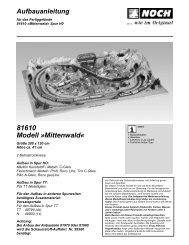
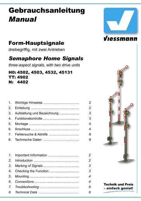
Gebrauchsanleitung<br />
<strong>Manual</strong><br />
Form-Hauptsignale<br />
dreibegriffig, mit zwei Antrieben<br />
Semaphore Home Signals<br />
three-aspect signals, with two drive units<br />
H0: 4502, 4503, 4532, 45131<br />
TT: 4902<br />
N: 4402<br />
1. Wichtige Hinweise ...................................... 2<br />
2. Einleitung ................................................... 2<br />
3. Aufstellung und Bezeichnung ..................... 3<br />
4. Funktionskontrolle ...................................... 3<br />
5. Montage ..................................................... 4<br />
6. Anschluss ................................................... 4<br />
7. Fehlersuche & Abhilfe ................................ 8<br />
8. Technische Daten ...................................... 8<br />
1. Important Information ................................. 2<br />
2. Introduction ................................................ 2<br />
3. Marking of Signals ...................................... 3<br />
4. Checking the Function ................................ 3<br />
5. Mounting ..................................................... 4<br />
6. Connections ............................................... 4<br />
7. Troubleshooting .......................................... 8<br />
8. Technical Data ........................................... 8
D<br />
1. Wichtige Hinweise<br />
Lesen Sie vor der ersten Benutzung des Produktes<br />
bzw. dessen Einbau diese Anleitung komplett<br />
und aufmerksam durch. Bewahren Sie diese Anleitung<br />
auf. Sie ist Teil des Produktes.<br />
Das Produkt richtig verwenden<br />
Das Produkt darf ausschließlich dieser Anleitung<br />
gemäß verwendet werden. Dieses Signalmodell<br />
ist bestimmt<br />
– zum Einbau in Modelleisenbahnanlagen<br />
– zum Anschluss an einen zugelassenen Modellbahntransformator<br />
bzw. an einer damit versorgten<br />
elektrischen Steuerung<br />
– zum Betrieb in trockenen Räumen<br />
Jeder darüber hinausgehende Gebrauch gilt als<br />
nicht bestimmungsgemäß. Für daraus resultierende<br />
Schäden haftet der Hersteller nicht.<br />
2. Einleitung<br />
Viessmann-Formsignale zeichnen sich durch vorbildgetreu<br />
langsame Flügelbewegung, ihr hervorragendes<br />
Preis-Leistungs-Verhältnis sowie durch<br />
einfache Montage und Anschlussmöglichkeit aus.<br />
Das vorliegende Formsignal verfügt über einen<br />
elektromagnetischen Antrieb, eine Endlagenabschaltung<br />
und über einen Kontakt zur Zugbeeinflussung.<br />
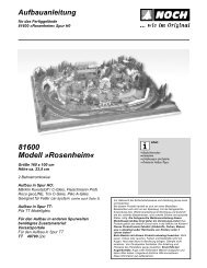
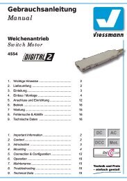
Viessmann-Formsignale haben sehr filigrane Masten,<br />
die sich durch eine perfekte Vorbildtreue auszeichnen.<br />
Daher sollten Sie das Signal nie am<br />
Mast anfassen, sondern immer nur an der Bodenplatte<br />
bzw. am Antriebszylinder (Abb. 1). Bei einem<br />
Ausbau aus der Modellbahnplatte nicht oben<br />
ziehen, sondern das Signal unter der Platte am<br />
Antriebszylinder greifen und nach oben hinausschieben!<br />
GB<br />
1. Important Information<br />
Please read this manual prior to first use of the<br />
product resp. its installation! This product must<br />
only be used as required in this manual. Keep this<br />
manual. It is part of the product.<br />
Using the product for it’s correct<br />
purpose<br />
This model of a signal is intended<br />
– for installation in model railroad layouts.<br />
– for connection to an authorized model railroad<br />
transformer or an electrical control system connected<br />
to one<br />
– for operation in a dry area<br />
Using the product for any other purpose is not<br />
approved and is considered incorrect. The<br />
manufacturer cannot be held responsible for any<br />
damage resulting from the improper use of this<br />
product.<br />
2. Introduction<br />
Viessmann-Semaphores have some outstanding<br />
benefits: Prototypical slow arm-movement, very<br />
good price-performance-ratio and they are simple<br />
to mount and connect.<br />
This signal has an electromagnetic drive unit, endposition-stop<br />
and an integrated contact for train<br />
control.<br />
Viessmann-Semaphores have finely detailed metal<br />
mast, which are very sensitive. Therefore you<br />
should never touch the masts but only the drive<br />
unit for installation and deinstallation (Fig. 1)<br />
If you have to unmount the signal, don’t pull the<br />
the signal-mast. Carefully take the drive unit instead<br />
and push it up.<br />
Abb. 1 Fig. 1 Abb. 2<br />
Fig. 2<br />
2
3. Aufstellung und Bezeichnung<br />
Hauptsignale stehen in Deutschland in der Regel<br />
in Fahrtrichtung gesehen rechts vom Gleis.<br />
Zweiflügelige Form-Hauptsignale können als Einoder<br />
Ausfahrsignale im Bahnhofsbereich oder als<br />
Blocksignale auf der Strecke eingesetzt werden.<br />
Damit ein Lokführer Signale richtig zuordnen<br />
oder im Störungsfall die richtige Meldung machen<br />
kann, werden die Signale mit einer Buchstaben- /<br />
Zahlenkombination gekennzeichnet. Die Bezeichnung<br />
des Signals gibt zusätzlich Auskunft über<br />
seinen Standort. Hier einige Richtlinien zur korrekten<br />
Beschriftung:<br />
Blocksignale: Selbstblocksignale werden mit arabischen<br />
Zahlen (1, 2, 3, …) bezeichnet. In Richtung<br />
der Kilometrierung der Strecke wird mit ungeraden<br />
Zahlen vorwärts gezählt (1, 3, 5, …), in der<br />
anderen Richtung mit geraden Zahlen rückwärts<br />
(z. B. 6, 4, 2, …).<br />
Einfahrsignale: In Zählrichtung der Kilometrierung<br />
der Strecke werden für Einfahrsignale die<br />
Buchstaben „A“ bis „E“, in Gegenrichtung „F“ bis<br />
„K“ verwendet.<br />
Ausfahrsignale: Ausfahrsignale, die in Zählrichtung<br />
stehen, werden mit „N“ bezeichnet. Ausfahrsignale,<br />
die entgegen der Zählrichtung stehen,<br />
werden mit „P“ bezeichnet.<br />
Hinter dem Buchstaben eines Ein- oder Ausfahrsignales<br />
steht die Ziffer des Gleises, für welches<br />
das Signal gilt.<br />
Damit Sie Ihre Signale korrekt beschriften können,<br />
liegt dem Signal eine Tafel mit selbstklebenden<br />
Bezeichnungsschildern bei. Schneiden Sie das<br />
gewünschte Schild aus, ziehen Sie die Schutzfolie<br />
ab und kleben Sie es auf die Nummerntafel am<br />
Mast des Signals (Abb. 2).<br />
Viele weitere Informationen über Signale finden<br />
Sie im Viessmann-Signalbuch, Artikel-Nr. 5299.<br />
4. Funktionskontrolle<br />
Nehmen Sie das Signal vorsichtig aus der Verpackung.<br />
Führen Sie vor der Montage eine Funktionskontrolle<br />
durch.<br />
Schließen Sie dazu das gelbe Kabel (ohne Markierung)<br />
an einem Pol eines 16 V-Modellbahntransformators<br />
– z. B. Viessmann 5200 – an.<br />
Verbinden Sie abwechselnd jeweils ein blaues Kabel<br />
mit dem anderen Pol des Trafos. Schließen<br />
Sie niemals die blauen Kabel gleichzeitig an.<br />
Das kann zur Zerstörung des Signals führen.<br />
Blau mit roter Markierung:<br />
Signal auf „Halt“ (Hp0), oberer Flügel waagerecht,<br />
3. Marking of Signals<br />
Adhesive signs are supplied with the signal. Simply<br />
cut out the desired sign and attach it to the<br />
signal box after removing the protecting foil. Here<br />
are some rules for the correct marking of the semaphore<br />
home signals:<br />
Signals are set on the right side of the track in<br />
germany. Three-aspect-signals can be used in<br />
stations and on the route.<br />
Home signals are marked with an alphanumeric<br />
combination The name of the signal gives information<br />
about its position and direction of the<br />
route.<br />
Block Signals: These signals are labeled with<br />
arabic numbers (1, 2, 3, ...). In direction of the<br />
kilometre count, the signals are counted with odd<br />
numbers (e. g. 1, 3, 5, ...). In the opposite direction<br />
the signals are counted with even numbers<br />
backwards ( e. g. 6, 4, 2, ...)<br />
Entry Signals: In direction of the kilometre count<br />
of the route, the signals are labeled with the letters<br />
“A” to “E”, in the opposite direction “F” to “K”.<br />
Exit Signals: In direction of the kilometre count<br />
of the route, the signals are labeled with the letter<br />
“N”, in the opposite direction with “P”.<br />
Additional to the letter of an entry- or exit-signal<br />
stands the number of the belonging track.<br />
4. Checking the Function<br />
Remove the signal from the box carefully. Check<br />
all functions prior to installation.<br />
Connect the yellow wire to one of the terminals<br />
of a 16 V transformer (AC/DC) e. g. Viessmann<br />
5200. Then alternately make contact between the<br />
blue cables and the other terminal, but only briefly.<br />
Never connect the blue cables at the same time to<br />
the transformer. This may destroy the signal.<br />
Connecting the cable results in the following armpositions:<br />
Blue with red marking:<br />
Signal on “Stop” (Hp0), upper arm horizontal,<br />
lower arm vertical.<br />
Blue with green marking:<br />
Signal on “Proceed” (Hp1), upper arm diagonal,<br />
lower arm vertical.<br />
Blue with yellow marking:<br />
Signal on “Proceed slowly” (Hp2), upper and lower<br />
arm diagonal.<br />
3
unterer Flügel senkrecht;<br />
Blau mit grüner Markierung:<br />
Signal auf „Fahrt“ (Hp1), oberer Flügel schräg<br />
nach oben, unterer Flügel senkrecht;<br />
Blau mit gelber Markierung:<br />
Signal auf „Langsamfahrt“ (Hp2), beide Flügel<br />
schräg nach oben.<br />
5. Montage<br />
1. Beschriften Sie das Signal (siehe Kapitel 3).<br />
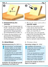
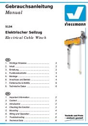
2. Sägen Sie an der Montagestelle ein Loch mit<br />
den Maßen 30 mm x 15 mm. Bohren Sie dazu<br />
zuerst 4 Löcher mit 6 mm Durchmesser. Verwenden<br />
Sie die in der Abbildung 3 abgedruckte<br />
Schablone.<br />
3. Führen Sie die Anschlusskabel von oben durch<br />
das Montageloch und stecken Sie dann das Signal<br />
mit dem Antrieb voran hinein.<br />
4. Befestigen Sie das Signal mit den beiliegenden<br />
Schrauben.<br />
6. Anschluss<br />
Alle Anschluss- und Montagearbeiten dürfen<br />
nur bei abgeschalteter Betriebsspannung<br />
durchgeführt werden!<br />
Verwenden Sie nur nach VDE /EN-gefertigte<br />
Modellbahntransformatoren!<br />
Sichern Sie die Stromquellen unbedingt so<br />
ab, dass es bei einem Kurzschluss nicht<br />
zum Kabelbrand kommen kann.<br />
Die Betriebsspannung beträgt 16 V = / ~.<br />
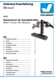
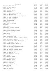
Schließen Sie nun das Signal gemäß den Abbildungen<br />
5 oder 7 an. Zur Bedeutung der Kabelfarben<br />
siehe Abbildung 4.<br />
Für die Versorgung der Signalbeleuchtung empfehlen<br />
wir einen separaten Transformator. Das<br />
5. Mounting<br />
1) Check that the signal works properly as per the<br />
instructions above before you start installing it<br />
on the layout.<br />
2) Letter the signal in accordance with the instructions<br />
on page 3.<br />
3) Saw a square hole of 30 mm x 15 mm at the<br />
mounting place. But before 4 holes of 6 mm diameter<br />
each should be drilled in the corners.<br />
Use the pattern which is shown in figure 3.<br />
4) The signal‘s connection wires have to be inserted<br />
into the hole first. After that put the signal<br />
with the drive first into that hole.<br />
5) Attach the signal to the baseboard with the enclosed<br />
screws.<br />
6. Connections<br />
Make sure that the power supply is switched<br />
off when you mount the device and connect<br />
the wires!<br />
Only use VDE/EN tested special model train<br />
transformers for the power supply!<br />
The power sources must be protected to prevent<br />
the risk of burning wires.<br />
The operating voltage is 16 V (AC/DC).<br />
Now make the electrical connection as per figure<br />
5 or 7. For the meaning of the cable colours refer<br />
to figure 4<br />
As a supply for the signal light, we recommend a<br />
separate transformer. This will prevent flickering of<br />
the lights due to high consumption of the drive.<br />
Connect the signal light to the transformer via the<br />
yellow cable with black marking and the brown cable<br />
with the diode.<br />
Abb. 3<br />
30 mm<br />
Ø 6 mm<br />
Fig. 3<br />
15 mm<br />
Ø 1 mm<br />
4
verhindert ein eventuelles Flackern der Beleuchtung<br />
beim Umschalten des Signales durch den erhöhten<br />
Strombedarf des Antriebes.<br />
Formsignal 4503: Beachten Sie das Zusatzblatt.<br />
Gleichstrombetrieb: Schließen Sie die beiden<br />
gelben Kabel an den Minuspol des Trafos an.<br />
Analoge Ansteuerung<br />
In Abbildung 7 zeigen wir Ihnen, wie einfach<br />
Sie die dreibegriffigen Formsignale mit Hilfe der<br />
Viessmann Tastenstellpulte 5546 (ohne Rückmeldung)<br />
oder 5548 (mit Rückmeldung durch LEDs)<br />
anschließen können. Schalter, Taster und Relais<br />
anderer Hersteller können Sie auch verwenden.<br />
Digitale Ansteuerung<br />
Viessmann-Formsignale können auch von einem<br />
Digitalsystem angesteuert werden (Abb. 5). Beim<br />
Anschluss z. B. an den Viessmann-Magnetartikel-Decoder<br />
5211 (Märklin / Motorola) müssen Sie<br />
darauf achten, dass neben den blauen Kabeln zur<br />
Signalsteuerung auch das gelbe Kabel (ohne Markierung)<br />
für die Stromversorgung angeschlossen<br />
ist. Zum digitalen Schalten eines dreibegriffigen<br />
Signals werden 1½ Ausgangsgruppen eines Magnetartikeldecoders<br />
benötigt. Die nicht benötigte<br />
Ausgangsbuchse kann für ein weiteres dreibegrif-<br />
Semaphore 4503:<br />
Refer to the additional information on the enclosed<br />
sheet.<br />
Direct current: Connect both yellow cables to the<br />
negative pole of the transfomer.<br />
Analogue Wiring<br />
The conventional wiring is shown in figure 7. It<br />
shows how you can connect the three-aspect<br />
form signals to a push-button panel (e. g. 5546 or<br />
5548).<br />
Power is supplied via the brown wire and the two<br />
yellow wires. The blue wires with the coloured<br />
markings are connected to contacts (single momentary<br />
switches, track contacts, automatic track<br />
switches, control panel), which in turn are wired to<br />
the brown lead ( = “ground”). Never supply power<br />
to more than one blue wire at the same time.<br />
The red wires are used to connect the insulated<br />
track section to the signal contacts (train control).<br />
Digital Control<br />
The semaphore home signals can also be operated<br />
with a digital system. Refer to figure 5 on the<br />
following page for the correct wiring.<br />
Simply connect the wires to a digital decoder<br />
(e.g. Viessmann 5211 for Märklin / Motorola for-<br />
Abb. 4<br />
blau mit gelber Markierung<br />
blue with yellow marking<br />
Signal Hp2 (Langsamfahrt)<br />
Signal Hp2 (Proceed slowly)<br />
Fig. 4<br />
blau mit roter Markierung<br />
blue with red marking<br />
Signal Hp0 (Halt)<br />
Signal Hp0 (Stop)<br />
blau mit grüner Markierung<br />
blue with green marking<br />
Signal Hp1 (Fahrt)<br />
Signal Hp1 (Proceed)<br />
gelb<br />
yellow<br />
gelb + Widerstand / Markierung<br />
yellow with resistor or marker<br />
braun (+Diode bei LED-Licht)<br />
brown (+diode for LED lighting)<br />
rot<br />
red<br />
rot<br />
red<br />
gemeinsamer Mittelpunkt der Antriebsspulen<br />
common pole for the drive coils<br />
Licht<br />
Light<br />
Licht (Masse)<br />
Light (ground)<br />
Kontakt für Zugbeeinflussung<br />
contact for train control<br />
Kontakt für Zugbeeinflussung<br />
contact for train control<br />
5
1 2 3 4 5 6 7 8<br />
figes Signal verwendet werden (zusammen mit<br />
einer anderen Ausgangsgruppe) oder für ein Entkupplungsgleis.<br />
Viessmann-Formsignale mit 2 Antrieben benötigen<br />
positive Schaltimpulse. Daher kann man die<br />
Signale nicht ohne weiteres mit allen Magnetartikeldecodern<br />
(z. B. von Lenz, Trix etc.) schalten,<br />
da diese Decoder negative Schaltimpulse liefern.<br />
Von Viessmann gibt es daher für alle Digitalsysteme<br />
Decoder, welche positive Schaltimpulse liefern!<br />
Der 5211 (4-fach) ist kompatibel zum Märklin / Motorola<br />
und Märklin-Systems-Format. Der 5212<br />
(4-fach) ist kompatibel zu allen DCC-Digitalsystemen<br />
wie z. B. Digital plus (Lenz), Arnold Digital,<br />
Roco Digital, Fleischmann Twin Center, Digitrax,<br />
Uhlenbrock Intellibox, Tillig Digital usw. . Der 5260<br />
(8-fach) ist kompatibel zum SELECTRIX ® -System<br />
(mit Sx-Bus-Anschluss).<br />
Abb. 5<br />
mat, 5212 for the NMRA DCC format or 5260 for<br />
SELECTRIX ® ).<br />
Viessmann-semaphores with two drive units need<br />
positive switching impulses. Therefore you cannot<br />
use any decoder (e. g. by Lenz, Trix etc.) because<br />
they use negative impulses.<br />
Viessmann delivers decoders for all digital systems<br />
and standards:<br />
5211: compatible with the Märklin / Motorola and<br />
Märklin-Systems format.<br />
5212: compatible with all DCC-systems e. g. Digital<br />
plus (Lenz), Arnold Digital, Roco Digital, Fleischmann<br />
Twin Center, Digitrax, Uhlenbrock Intellibox,<br />
Tillig Digital etc.<br />
5260: compatible with the SELECTRIX ® -System<br />
with Sx-Bus.<br />
Fig. 5<br />
Zu weiteren<br />
Decodern<br />
to further<br />
decoders<br />
E<br />
braun brown<br />
rot<br />
red<br />
16 V = / ~<br />
Viessmann-Formsignale<br />
mit zwei Antrieben<br />
z. B. Entkupplungsgleis<br />
e. g. uncouplers<br />
Viessmann semaphores<br />
with two drive units<br />
braun brown<br />
rot red<br />
rt bn E gn 4 rt gn 3 rt<br />
Adresse<br />
ON<br />
WP<br />
Viessmann<br />
5211<br />
Magnetartikeldecoder<br />
rt bn rt 1 gn rt 2 gn<br />
gelb yellow<br />
blau<br />
blue<br />
gelb mit schwarzer<br />
Markierung<br />
yellow with black<br />
marking<br />
braun brown<br />
rot red<br />
1,5 kΩ<br />
1/4 Watt<br />
16 V = / ~<br />
Abb. 6<br />
1. 2. 3.<br />
Fig. 6<br />
Nadel oder<br />
dünner Draht<br />
Needle or<br />
thin wire<br />
Diese Maßnahme<br />
darf nur im stromlosen<br />
Zustand ausgeführt<br />
werden!<br />
Switch off power<br />
before doing this!<br />
6
Abb. 7<br />
Fig. 7<br />
Beachten Sie die<br />
Anschlusshinweise in<br />
Kap. 6, S. 5<br />
System<br />
Märklin H0<br />
Note the connecting<br />
instructions in chap. 6<br />
on p. 5<br />
rot<br />
red<br />
Steuermodul. Nicht entfernen!<br />
Control Unit. Do not remove!<br />
Formsignal<br />
mit zwei Antrieben.<br />
blau blue<br />
rot red<br />
grün green<br />
gelb yellow<br />
Tasten - Stellpult<br />
rot<br />
red<br />
Semaphore Signal<br />
with two drive units.<br />
rot<br />
red<br />
braun<br />
brown<br />
braun<br />
brown<br />
gelb yellow<br />
Viessmann<br />
braun<br />
brown<br />
16 V<br />
5548<br />
z. B.<br />
5548<br />
Steuermodul. Nicht entfernen!<br />
Control Unit. Do not remove!<br />
blau blue<br />
rot red<br />
grün green<br />
gelb yellow<br />
Tasten - Stellpult<br />
rot<br />
red<br />
braun<br />
brown<br />
braun<br />
brown<br />
gelb yellow<br />
16 V<br />
Viessmann<br />
braun<br />
brown<br />
5548<br />
z. B.<br />
5548<br />
Dieses Symbol neben dem<br />
Gleis kennzeichnet eine<br />
Trennstelle (Gleichstrom =<br />
rechte Schiene in Fahrtrichtung,<br />
Wechselstrom = Mittelleiter).<br />
This sign beside the track indicates<br />
a track insulation (DC<br />
= right rail in driving direction,<br />
AC = third rail).<br />
7
7. Fehlersuche<br />
Jedes Viessmann-Produkt wird unter hohen Qualitätsstandards<br />
gefertigt und vor seiner Auslieferung<br />
geprüft. Sollte es dennoch zu einer Störung<br />
kommen, können Sie anhand der folgenden Punkte<br />
eine erste Überprüfung vornehmen. Testen Sie<br />
jedoch zuvor die Stromzuführungen.<br />
1. Die Flügel stehen nicht gerade:<br />
Signal auf Stellung „Halt“ (Hp0) stellen und Flügel<br />
vorsichtig gerade stellen. Jeder Flügel lässt<br />
sich auf seiner Drehachse verstellen. Unter<br />
Umständen müssen Sie die auf der Rückseite<br />
befindlichen Anschläge etwas nachrichten.<br />
2. Das Signal schaltet hörbar, die Flügel bewegen<br />
sich jedoch nicht oder nur teilweise:<br />
Hubstangen vorsichtig etwas nach oben oder<br />
unten bewegen. Eventuell die Hubstangen<br />
oben lösen und prüfen, ob die Flügelmechaniken<br />
sich widerstandslos bewegen lassen.<br />
3. Die Signallampen leuchten, die Stromzuführung<br />
ist zweifelsfrei in Ordnung, das Signal<br />
schaltet aber nicht:<br />
Der innenliegende Richtungsumschalter hat<br />
möglicherweise keinen Kontakt. Abhilfe: Strom<br />
abschalten! Schutzkappe unten am Signalantrieb<br />
abziehen und den Schaltkontakt mit Hilfe<br />
einer Stecknadel oder eines dünnen Drahtes<br />
einmal nach oben bewegen (Fig. 6).<br />
Sollte das Produkt beschädigt sein, geben Sie es<br />
in der zugehörigen Verpackung zu Ihrem Fachhändler<br />
oder senden Sie es direkt an den<br />
Viessmann-Service (Adresse siehe unten).<br />
8. Technische Daten<br />
Betriebsspannung: 16 V =/~<br />
Stromaufnahme<br />
(im Schaltmoment, ca. 0,1 s):<br />
Maximale Belastbarkeit<br />
des Fahrstromkontaktes:<br />
0,7 A<br />
2 A<br />
7. Troubleshooting<br />
Every Viessmann-product is manufactured under<br />
high quality standards and is tested before delivery.<br />
If there is a fault nevertheless, you can do a<br />
first check. At first check the power supply.<br />
1. The arms are not straight:<br />
Set the signal to the Hp0 aspect (Stop) and adjust<br />
the arm back to the straight position very<br />
careful! The bar can be shifted on its axle.<br />
2. The switch sound of the signal drive can be<br />
heard, but the arm doesn‘t move or moves<br />
only a little bit.<br />
Move the lifting rod very carefully a bit up and<br />
down (if necessary detach the lifting rod from<br />
the bar lever and check if bar mechanics can<br />
be moved without resistance).<br />
3. The signal lamp lights and the power supply<br />
doubtless is in good order, however the signal<br />
doesn‘t switch.<br />
Possible reason: The inner limit switch hasn‘t<br />
got any contact.<br />
Switch off the electrical power!! Than move up<br />
the switch contact by means of a pin or a thin<br />
wire (refer to figure 6).<br />
If the product is damaged, send it in the original<br />
package directly for repair to your local dealer or<br />
to the Viessmann company (see below for address).<br />
8. Technical Data<br />
Operating voltage:<br />
Peak inrush current (for approx. 0.1 s):<br />
Max. contact load of<br />
the track control contact:<br />
16 V AC/DC<br />
0.7 A<br />
2 A<br />
Dieses Produkt ist kein Spielzeug. Nicht geeignet für<br />
Kinder unter 14 Jahren! Anleitung aufbewahren!<br />
This product is not a toy. Not suitable for children<br />
under 14 years! Keep these instructions!<br />
Ce produit n’est pas un jouet. Ne convient pas aux<br />
enfants de moins de 14 ans ! Conservez ce mode<br />
d’emploi !<br />
Dit produkt is geen speelgoed. Niet geschikt voor kinderen<br />
onder 14 jaar! Gebruiksaanwijzing bewaren!<br />
Questo prodotto non è un giocattolo. Non adatto a<br />
bambini al di sotto dei 14 anni! Conservare instruzioni<br />
per l’uso!<br />
Esto no es un juguete. No recomendado para menores<br />
de 14 años! Conserva las instrucciones de servicio!<br />
8<br />
Modellspielwaren GmbH<br />
08/2006 2/2007 Bau Ko<br />
Stand 03<br />
Sach-Nr. 98477 98424<br />
Made Made in in Europe