Viessmann Anleitung Weichenantrieb 4554 - Reynaulds
Viessmann Anleitung Weichenantrieb 4554 - Reynaulds
Viessmann Anleitung Weichenantrieb 4554 - Reynaulds

Erfolgreiche ePaper selbst erstellen
Machen Sie aus Ihren PDF Publikationen ein blätterbares Flipbook mit unserer einzigartigen Google optimierten e-Paper Software.
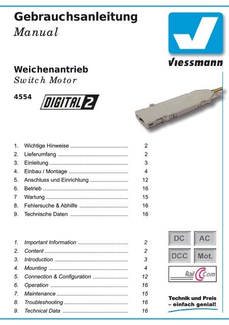
Gebrauchsanleitung<br />
Manual<br />
<strong>Weichenantrieb</strong><br />
Switch Motor<br />
<strong>4554</strong><br />
1. Wichtige Hinweise ...................................... 2<br />
2. Lieferumfang .............................................. 2<br />
3. Einleitung .................................................... 3<br />
4. Einbau / Montage ....................................... 4<br />
5. Anschluss und Einrichtung ......................... 12<br />
6. Betrieb ........................................................ 16<br />
7 Wartung ...................................................... 15<br />
8. Fehlersuche & Abhilfe ................................ 16<br />
9. Technische Daten ...................................... 16<br />
1. Important Information ................................. 2<br />
2. Content ....................................................... 2<br />
3. Introduction ................................................ 3<br />
4. Mounting .................................................... 4<br />
5. Connection & Configuration ....................... 12<br />
6. Operation ................................................... 16<br />
7. Maintenance ............................................... 15<br />
8. Troubleshooting .......................................... 16<br />
9. Technical Data ........................................... 16
DE<br />
1. Wichtige Hinweise<br />
Lesen Sie vor der ersten Benutzung des Produktes bzw.<br />
dessen Einbau diese <strong>Anleitung</strong> komplett und aufmerksam<br />
durch. Bewahren Sie diese <strong>Anleitung</strong> auf. Sie ist Teil des<br />
Produktes.<br />
Das Produkt richtig verwenden<br />
Das Produkt darf ausschließlich dieser <strong>Anleitung</strong> gemäß<br />
verwendet werden. Dieser Antrieb ist bestimmt<br />
• zum Einbau an / in eine Modelleisenbahnweiche<br />
• zum Betrieb mit einer konventionellen Modellbahnsteuerung<br />
oder einer Digitalzentrale, welche die Digitalsysteme<br />
Märklin-Motorola und / oder NMRA-<br />
DCC verwendet<br />
• zum Betrieb in trockenen Räumen.<br />
Jeder darüber hinausgehende Gebrauch gilt als nicht<br />
bestimmungsgemäß. Für daraus resultierende Schäden<br />
haftet der Hersteller nicht.<br />
2. Lieferumfang<br />
Beachten Sie:<br />
Der Antrieb besteht aus einer empfindlichen Elektronik<br />
und Mechanik. Öffnen Sie nur den vorderen<br />
Deckel zum Einsatz der passenden Abtriebshebel.<br />
Öffnen Sie das weitere Gehäuse unter keinen<br />
Umständen. Zerstörung des Antriebs oder Verletzungen<br />
können die Folge sein.<br />
Packungsinhalt überprüfen<br />
Kontrollieren Sie nach dem Auspacken den Lieferumfang<br />
auf Vollständigkeit:<br />
► <strong>Weichenantrieb</strong> mit Anschlusskabeln,<br />
► Beutel mit Zubehörteilen zum Anbau des Antriebes an<br />
verschiedene Weichentypen (Inhalt s.Abb. 1),<br />
► diese <strong>Anleitung</strong>.<br />
EN<br />
1. Important Information<br />
Please read this manual prior to first use of the product<br />
resp. its installation! Keep this manual. It is part of the<br />
product.<br />
Using the product for it’s correct<br />
purpose<br />
This product must only be used as required in this<br />
manual. This switch motor is intended<br />
• for installation in turnouts of model railroad layouts,<br />
• for connection to an authorized model railroad transformer<br />
or an electrical control system connected to<br />
one or a digital command system (DCC or Mot.),<br />
• for operation in a dry area.<br />
Using the product for any other purpose is not approved<br />
and is considered incorrect. The manufacturer<br />
cannot be held responsible for any damage resulting<br />
from the improper use of this product.<br />
2. Content<br />
Caution:<br />
The switch motor contains very sensitive mechanical<br />
and electronical components.<br />
You must only open the front cover of the casing<br />
to put in the appropriate lever. Never open the<br />
back cover of the switch motor. That may result in<br />
destruction of the motor or injury.<br />
Checking the package contents<br />
Check the contents of the package for completeness<br />
after unpacking:<br />
► turnout drive unit with cables,<br />
► bag with different adapters and levers to mount the<br />
drive to different turnout types (content see figure 1),<br />
► this manual.<br />
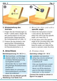
Abb. 1<br />
Fig. 1<br />
4<br />
12<br />
1<br />
6<br />
5<br />
3 x (3,5 x 3 mm)<br />
1 x (3,8 x 1,5 mm)<br />
7<br />
2<br />
10<br />
13<br />
3<br />
8<br />
9 11 2 x (2,2 x 6,0 mm)<br />
3 x (2,2 x 9,5 mm)<br />
2
1) Märklin C-Gleis (DKW)<br />
2) Märklin C-Gleis (Dreiwegweiche)<br />
3) Märklin C-Gleis (einfache Weiche)<br />
4) Roco GeoLine<br />
5) Roco GeoLine (Stelldraht)<br />
6) Roco Line mit Bettung<br />
7) Fleischmann Profigleis<br />
8) Adapter für 90°-Abtriebe<br />
9) Roco Line ohne Bettung, Piko A, Peco Streamline<br />
10) Märklin K-Gleis<br />
11) Tillig H0 Elite<br />
12) Distanzhülsen (4 Stück)<br />
13) Befestigungsschrauben (5 Stück)<br />
3. Einleitung<br />
Funktionsumfang<br />
Der <strong>Viessmann</strong> <strong>Weichenantrieb</strong> ist ein kraftvoller Universalantrieb<br />
mit integriertem Digitaldecoder zum Einbau in<br />
H0-Bettungsweichen sowie als Unterflur- oder unauffälliger<br />
Oberflurantrieb für Weichen verschiedener Hersteller<br />
und Baugrößen.<br />
Der <strong>Viessmann</strong> <strong>Weichenantrieb</strong> zeichnet sich durch seine<br />
vorbildgerecht langsame Bewegung der Weichenzungen<br />
aus. Geschwindigkeit und Bewegungsablauf sind elektronisch<br />
gesteuert und gewährleisten so einen feinfühligen<br />
Antrieb. Der Motor fährt nach Erreichen der jeweiligen<br />
Endlage immer in eine Mittelposition ohne den Stellschieber<br />
mit zu nehmen. Auf diese Weise ist auch Handbetätigung<br />
der Weiche möglich, ohne den Antrieb zu beschädigen.<br />
Der integrierte Decoder versteht die Formate Märklin-Motorola<br />
und DCC und kann die angeforderte Sollstellung<br />
per RailCom ® an geeignete Digitalzentralen zurückmelden.<br />
Zusätzliche Kontakte für konventionelle Stellungsrückmeldung<br />
vervollständigen den Funktionsumfang.<br />
Geeignete Gleissysteme<br />
Für die unten aufgeführten Gleissysteme befinden sich<br />
im Lieferumfang geeignete Hebel zur direkten Montage.<br />
Weitere Gleissysteme und Weichentypen auch anderer<br />
Baugrößen sind prinzipiell ebenfalls verwendbar. Zur<br />
Montage ist dann jedoch etwas Geschick erforderlich. Die<br />
beigefügten Hebel lassen sich je nach Weichentyp auch<br />
für andere Weichen verwenden.<br />
► Märklin C- und K-Gleis<br />
► Roco Line mit und ohne Bettung<br />
► Roco GeoLine (nicht Nr. 61160 / 61164)<br />
► Fleischmann H0 Modellgleis<br />
► Fleischmann H0 Profigleis<br />
► Piko A-Gleis<br />
► Tillig H0 Elite<br />
► Peco Streamline (Code 75)<br />
Ansteuerung im Digitalbetrieb<br />
Der <strong>Weichenantrieb</strong> <strong>4554</strong> enthält einen Multiprotokoll-<br />
Decoder, der entweder Signale im DCC-Format oder im<br />
Motorola-Format auswertet. Welches Datenformat der<br />
1) Märklin C-track (double slip switch)<br />
2) Märklin C-Gleis (three way turnout)<br />
3) Märklin C-Gleis (single turnout)<br />
4) Roco GeoLine<br />
5) Roco GeoLine<br />
6) Roco Line with ballast<br />
7) Fleischmann profi track<br />
8) Adapter for 90°<br />
9) Roco Line without ballast, Piko A, Peco Streamline<br />
10) Märklin K-track<br />
11) Tillig H0 Elite<br />
12) distance rolls (4 pieces)<br />
13) screws (5 pieces)<br />
3. Introduction<br />
Functions<br />
The <strong>Viessmann</strong> Switch motor is a powerful universal<br />
drive unit with integrated digital decoder. It can be<br />
mounted in H0-turnouts with bed of ballast or underfloor<br />
or overfloor. The switch motor is compatible with turnouts<br />
of different manufacturers.<br />
The <strong>Viessmann</strong> switch motor has an extraordinary and<br />
thus very realistic slow movement of the point rails.<br />
Speed and motion are controlled by the built in electronic<br />
which warrants a very sensitive adjustment.<br />
The motor takes up a middle position after reaching the<br />
end position, without taking the lever with it. This makes it<br />
possible, to switch the turnouts by hand.<br />
The integrated decoder is suitable for DC / AC, MM and<br />
DCC and is able to send the requested position by Rail-<br />
Com ® to corresponding digital command stations. Additional<br />
contacts for a conventional feedback complete the<br />
functions of the switch motor.<br />
Compatible Track Systems<br />
The list below shows the track systems of different manufacturers,<br />
for which levers are included in the package.<br />
Further track systems – and other gauges – can be used<br />
too, but there are no specific levers etc. available, so you<br />
need to handicraft a little bit. The enclosed levers can be<br />
used for other track systems too.<br />
► Märklin C- and K-Gleis<br />
► Roco Line with and without ballast<br />
► Roco GeoLine (not No. 61160 / 61164)<br />
► Fleischmann H0 model track<br />
► Fleischmann H0 profi track<br />
► Piko A-track<br />
► Tillig H0 Elite<br />
► Peco Streamline (Code 75)<br />
Operation in digital mode<br />
The switch motor contains a multiple protocol decoder,<br />
that can operate with and automatically recognises both<br />
DCC or Motorola formats.<br />
The number of addresses depends on the format being<br />
used.<br />
3
4<br />
Decoder auswertet legt man bei der Einstellung der Digitaladresse<br />
fest.<br />
Der Adressumfang ist von dem Format abhängig, mit<br />
dem der Decoder angesteuert wird.<br />
Motorola-Format: 255 Adressen.<br />
DCC- Format: 2048 Adressen.<br />
Ansteuerung im Analogbetrieb<br />
Den <strong>Viessmann</strong> <strong>Weichenantrieb</strong> können Sie auch in konventionell<br />
gesteuerten Modellbahnanlagen einsetzen.<br />
Sie können ihn sowohl mit Wechselstrom- als auch mit<br />
Gleichstrom betreiben.<br />
Sobald Sie den Antrieb an Betriebsspannung anschließen,<br />
erkennt der integrierte Decoder automatisch, ob er<br />
analog oder digital angesteuert wird, und stellt den entsprechenden<br />
Betriebsmodus ein.<br />
Verhalten bei Überlastung<br />
Bei Kurzschlüssen oder anderer Überlastung schaltet der<br />
<strong>Weichenantrieb</strong> nach einer Zeit von ca. 2 Sekunden ab<br />
und fährt in die Mittelstellung zurück.<br />
Rückmeldung mit RailCom ®<br />
RailCom ® ist ein Zusatzprotokoll zur bidirektionalen Kommunikation<br />
in digitalen Modellbahnanlagen, die im DCC-<br />
Format gesteuert werden. Es ermöglicht z. B. die Stellungsrückmeldung<br />
der Weiche zur Digitalzentrale.<br />
Das Versenden von RailCom-Messages ist nur in Anlagen<br />
möglich, in denen ein DCC-Signal an den Schienen<br />
anliegt und seitens der Zentrale sowie der Booster eine<br />
entsprechende Austastlücke im Datenstrom erzeugt wird.<br />
Daher ist die Nutzung der RailCom-Funktion in einer reinen<br />
Motorola-Umgebung nicht möglich.<br />
Sofern der Decoder im <strong>Weichenantrieb</strong> die Austastlücke<br />
registriert, sendet er nach einem erhaltenen Schaltbefehl<br />
als Quittung die Sollstellung der Weiche zurück.<br />
4. Einbau / Montage<br />
Beachten Sie: Sowohl mechanische als auch<br />
elektronische Bauteile im Inneren des <strong>Weichenantrieb</strong>s<br />
sind sehr empfindlich. Arbeiten Sie also<br />
sehr vorsichtig!<br />
Sicherheitshinweis: Alle Anschluss- und Montagearbeiten<br />
dürfen nur bei abgeschalteter Betriebsspannung<br />
durchgeführt werden.<br />
Allgemeine Hinweise<br />
Der <strong>Viessmann</strong> <strong>Weichenantrieb</strong> ist als Universalantrieb<br />
für unterschiedliche Weichentypen konzipiert. Im Gehäuse<br />
ist die elektronische Steuerung inklusive Digitaldecoder<br />
sowie der Antriebsmotor inklusive mechanischem Teil<br />
untergebracht (Gewindespindel, Abtriebshebel, Getriebe).<br />
Der <strong>Weichenantrieb</strong> kann in jeder Lage montiert werden,<br />
abhängig vom Weichentyp und Gleissystem.<br />
Das Gehäuse ist systembedingt nicht hermetisch versiegelt.<br />
Durch die Öffnungen im Gehäuse können Kleinteile<br />
wie Streumaterial etc. ins Innere gelangen und den Antrieb<br />
zerstören.<br />
Beachten Sie daher unbedingt die folgenden Hinweise:<br />
Motorola-Format:<br />
DCC- Format:<br />
255 addresses.<br />
2048 addresses.<br />
Operation in analogue mode<br />
The <strong>Viessmann</strong> switch motor can be used in conventional<br />
model railroad layouts. You may use AC or DC power<br />
supply for operation.<br />
The integrated controller and decoder recognizes automatically<br />
if there is AC or DC power supply or a digital<br />
signal and adjusts itself to the correct mode of operation.<br />
Overload protection<br />
If the switch motor recognizes a short circuit or an overload,<br />
it switches off to protect itself against destruction. At<br />
first, the motor brings the drive to the mid-position. The<br />
whole process of switching off may last up to 2 seconds.<br />
Feedback with RailCom ®<br />
RailCom ® is a log for bi-directional communication in<br />
digital model railway layouts controlled in DCC-format. It<br />
allows e. g. the feedback of the address or the requested<br />
position from the switch motor to the digital control unit.<br />
Sending RailCom ® messages is only possible in layouts<br />
with a DCC signal on the rails and if the command station<br />
and / or the booster(s) generate a cut-out in the digital<br />
signal. That’s why it is not possible to use RailCom ® in a<br />
Motorola-system without DCC.<br />
Whether the decoder of the switch motor registers the<br />
RailCom cut-out, it sends back after an order it’s own<br />
address and the requested position of the turnout to<br />
acknowledge that it has receipt the order (so-called Rail-<br />
Com broadcast datagramm).<br />
4. Mounting and Connections<br />
Notice:<br />
Be careful with the switch motor. Mechanical and<br />
as well as electronical components in the switch<br />
motor are very sensitive.<br />
Caution:<br />
Make sure that the power supply is switched<br />
off when you mount the device and connect the<br />
wires!<br />
General notice<br />
The <strong>Viessmann</strong> switch motor is an universal drive for different<br />
types of turnouts. The case contains the electronic<br />
control unit including the digital decoder and the drive unit<br />
(motor, gear unit, thread and lever).<br />
The switch motor may be mounted in every position. The<br />
used mounting place and position of the switch motor depends<br />
on the used track system and turnout type.<br />
The case is not hermetically sealed due to it’s concept.<br />
Small parts like ballast etc. may get into the casing<br />
through the openings and destroy the switch motor!<br />
Therefore pay attention to the following notices:
Achten Sie bei der Montage auf der Grundplatte<br />
darauf, dass die Oberfläche eben und sauber ist.<br />
Unter dem <strong>Weichenantrieb</strong> darf kein Streumaterial<br />
(Steine, Schotter etc.) verwendet werden. Ansonsten<br />
können Getriebegehäuse und Mechanik verformt<br />
und zerstört werden.<br />
Achten Sie unbedingt darauf, dass kein Streumaterial<br />
durch die Öffnungen des Gehäuses ins<br />
Innere gelangen kann.<br />
<strong>Weichenantrieb</strong> vorbereiten<br />
Um den <strong>Weichenantrieb</strong> ordnungsgemäß an einer Weiche<br />
zu montieren, sind einige vorbereitende Arbeiten erforderlich.<br />
Sorgen Sie bitte als erstes für eine aufgeräumte<br />
und saubere Arbeitsfläche. Legen Sie sich außerdem<br />
folgendes Werkzeug bereit: eine feine Pinzette (möglichst<br />
aus Kunststoff) sowie einen kleinen Schraubendreher<br />
(Schlitz) zum vorsichtigen Abhebeln des Deckels.<br />
1. Legen Sie den für Ihre Weiche passenden Hebel<br />
bereit (aus dem Zubehörbeutel, s. a. Abb. 1).<br />
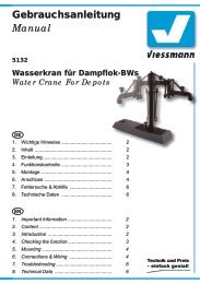
2. Öffnen Sie vorsichtig den vorderen Deckel des<br />
<strong>Weichenantrieb</strong>s (Abb. 2) und legen Sie ihn beiseite.<br />
Damit sind die Vorbereitungen abgeschlossen. Folgen<br />
Sie nun den speziellen Hinweisen zu Ihrem Weichentyp<br />
weiter unten.<br />
Abb. 2<br />
When mounting the switch motor, the ground plate<br />
has to be even and clean.<br />
Below the switch motor there must not be any material<br />
like ballast etc. Otherwise the casing could<br />
be deformed and the mechanical parts could be<br />
destroyed.<br />
Prevent small materials like e.g. ballast from getting<br />
into the casing.<br />
Preparing the switch motor<br />
To mount the switch motor at a turnout, some preparations<br />
are necessary. At first you need a clean workplace.<br />
For the following work you need these tools: A small<br />
tweezer (if possible, use some made of plastic) and a<br />
small screwdriver to open the casing.<br />
1. Choose the lever, which fits for your turnout / track<br />
system (see figure 1).<br />
2. Carefully open the front cover of the casing of the<br />
switch (see figure 2)<br />
Follow now the specific instructions for your turnout /<br />
track system. You’ll find these instructions below.<br />
Fig. 2<br />
1. Halterungen abspreizen<br />
2. Deckel abheben<br />
3. gewünschten Hebel einsetzen<br />
4. Deckel wieder aufsetzen und einrasten<br />
1. Spread off fixtures<br />
2. Take off front cover carefully<br />
3. Put in the corresponding lever<br />
4. Put the cover back on casing<br />
Märklin C-Gleis (einfache Weiche)<br />
Hebel: 3<br />
Montage: in Bettung<br />
1. Montieren Sie Hebel 3 gemäß Abbildung 3.1 im <strong>Weichenantrieb</strong><br />
und verschließen Sie anschließend das<br />
Gehäuse wieder mit dem Deckel.<br />
2. Bringen Sie die Weiche in die zum Antrieb passende<br />
Stellung (Der Hebel des <strong>Weichenantrieb</strong>s muss in den<br />
Hebel der Weiche greifen).<br />
3. Legen Sie den <strong>Weichenantrieb</strong> gemäß Abbildung 3.2<br />
in die Bettung der Weiche und fixieren Sie ihn mit den<br />
passenden Schrauben 2 x Nr. 13.<br />
Märklin C-track (single turnout)<br />
Lever: 3<br />
Mounting: Into bed of ballast<br />
1. Mount lever 3 as shown in figure 3.1 into the switch<br />
motor. After mounting the lever, close the casing with<br />
the cover.<br />
2. Bring the turnout into the corresponding position of the<br />
switch motor (the lever of the switch motor has to get<br />
connected with the lever of the turnout).<br />
3. Put the switch motor into the intended empty space of<br />
the turnout as shown in figure 3.2.<br />
Fix the switch motor with the screws 2 x nr. 13.<br />
5
Abb. 3<br />
3.1 3.2 3.3<br />
2,2 x 6 mm<br />
Fig. 3<br />
Märklin C-Gleis (Dreiwegweiche)<br />
Hebel: 2 und 3<br />
Montage: in Bettung<br />
Zum Antrieb der Dreiwegweiche benötigen Sie zwei<br />
<strong>Viessmann</strong> <strong>Weichenantrieb</strong>e.<br />
1. Montieren Sie die beiden Hebel gemäß Abbildung 3.1<br />
(oben) in den <strong>Weichenantrieb</strong>en und verschließen Sie<br />
anschließend die Gehäuse wieder.<br />
2. Bringen Sie die Weiche in die zu den Antrieben passende<br />
Stellung (Die Hebel der <strong>Weichenantrieb</strong>e müssen<br />
in die Hebel der Weiche greifen).<br />
3. Legen Sie die <strong>Weichenantrieb</strong>e gemäß Abbildung 4.1<br />
in die Bettung der Weiche und fixieren Sie sie mit den<br />
passenden Schrauben 4 x Nr. 13 (Abb. 4.2).<br />
Märklin C-track (Three-Way Turnout)<br />
Lever: 2 and 3<br />
Mounting: Into bed of ballast<br />
To drive this turnout, you need two <strong>Viessmann</strong> switch motors<br />
(one for each turning).<br />
1. Mount the two levers as shown in figure 3.1 into the<br />
switch motor. After mounting the lever, close the casing<br />
with the cover.<br />
2. Bring the turnout into the corresponding positions of<br />
the switch motors (the levers of the switch motors<br />
have to get connected with the levers of the turnout).<br />
3. Put the switch motors into the intended empty space<br />
of the turnout as shown in figure 4.1.<br />
Fix the switch motors with the screws 4 x nr. 13.<br />
Abb. 4<br />
4.1 4.2<br />
Fig. 4<br />
2,2 x 6 mm<br />
6
Märklin C-Gleis (DKW)<br />
Hebel: 1<br />
Montage: in Bettung<br />
1. Montieren Sie den Hebel gemäß Abbildung 3.1 (links)<br />
im <strong>Weichenantrieb</strong> und verschließen Sie anschließend<br />
das Gehäuse wieder.<br />
2. Bringen Sie die Doppelkreuzungsweiche in die zum<br />
Antrieb passende Stellung (Der Hebel des <strong>Weichenantrieb</strong>s<br />
muss in den Hebel der DKW greifen).<br />
3. Legen Sie den <strong>Weichenantrieb</strong> gemäß Abbildung 5 in<br />
die Bettung der Weiche und fixieren Sie ihn mit den<br />
passenden Schrauben 2 x Nr. 13.<br />
Abb. 5<br />
5.1 5.2<br />
Märklin C-track (Double Slip Switch)<br />
Lever: 1<br />
Mounting: Into bed of ballast<br />
1. Mount lever 1 as shown in figure 3.1 into the switch<br />
motor. After mounting the lever, close the casing with<br />
the cover.<br />
2. Bring the Switch into the corresponding position of the<br />
switch motor (the lever of the switch motor has to get<br />
connected with the lever of the switch).<br />
3. Put the switch motor into the intended empty space of<br />
the turnout as shown in figure 5.<br />
Fix the switch motor with the screws 2 x nr. 13.<br />
2,2 x 6 mm<br />
Fig. 5<br />
Roco-Line (ohne Bettung)<br />
Hebel: 8 und 9<br />
Montage: oberflur, neben Gleis<br />
1. Montieren Sie die Hebel gemäß Abbildung 6.1 im <strong>Weichenantrieb</strong><br />
und verschließen Sie anschließend das<br />
Gehäuse wieder.<br />
2. Entfernen Sie den markierten Befestigungsring an der<br />
Einkerbung mit einem scharfen Messer.<br />
3. Bringen Sie die Weiche in die zum Antrieb passende<br />
Stellung (Der Hebel des <strong>Weichenantrieb</strong>s muss in den<br />
Hebel der Weiche greifen).<br />
4. Montieren Sie den Antrieb neben der Weiche (Abb.<br />
6.2) und fixieren Sie ihn mit den passenden<br />
Distanzhülsen und Schrauben 2 x Nr. 13.<br />
Bei Verwendung der EKW und der DKW entfernen Sie<br />
bitte den Steg im Hebel 9 (Abb. 9.1) und montieren Sie<br />
den Antrieb mit dem Deckel nach unten.<br />
Abb. 6<br />
Roco-Line (without ballast)<br />
Lever: 8 and 9<br />
Mounting: Overground, beside the track<br />
1. Mount lever 1 as shown in figure 6.1 into the switch<br />
motor. After mounting the lever, close the casing with<br />
the cover.<br />
2. Cut off the fastening ring at the notch with a sharp<br />
knife as shown in figure 6.1.<br />
3. Bring the turnout into the corresponding position of the<br />
switch motor (the lever of the switch motor has to get<br />
connected with the lever of the turnout).<br />
4. Mount the switch motor beside the turnout as shown<br />
in figure 6.2. Fix the switch motor with the screws 2 x<br />
nr. 13. Use the distance rolls!<br />
When using a slip switch, cut off the bridge in lever 9 (see<br />
figure 9.1) and mount the switch motor with the cover to<br />
the ground.<br />
Fig. 6<br />
6.1 6.2 6.3<br />
7
Roco-Line (mit Bettung)<br />
Hebel: 6<br />
Montage: in Bettung<br />
1. Montieren Sie den Hebel gemäß Abbildung 7.1 im<br />
<strong>Weichenantrieb</strong> und verschließen Sie anschließend<br />
das Gehäuse wieder.<br />
2. Entfernen Sie die markierten Befestigungsringe an<br />
den Einkerbungen mit einem scharfen Messer.<br />
3. Bringen Sie die Weiche in die zum Antrieb passende<br />
Stellung (Der Hebel des <strong>Weichenantrieb</strong>s muss in den<br />
Hebel der Weiche greifen).<br />
4. Montieren Sie den Antrieb mit dem Deckel nach unten<br />
in der Weiche (Abb. 7.2).<br />
Abb. 7<br />
7.1 7.2 7.3<br />
Roco-Line (with bed of ballast)<br />
Lever: 6<br />
Mounting: Into bed of ballast<br />
1. Mount lever 6 as shown in figure 7.1 into the switch<br />
motor. After mounting the lever, close the casing with<br />
the cover.<br />
2. Cut off the fastening rings at the notch with a sharp<br />
knife as shown in figure 7.1.<br />
3. Bring the turnout into the corresponding position of the<br />
switch motor (the lever of the switch motor has to get<br />
connected with the lever of the turnout).<br />
4. Mount the switch motor into the intended empty space<br />
of the turnout as shown in figure 7.2.<br />
Fig. 7<br />
Fleischmann H0 Profigleis<br />
Hebel: 7<br />
Montage: oberflur, neben Gleis<br />
1. Montieren Sie den Hebel gemäß Abbildung 8.1 im<br />
<strong>Weichenantrieb</strong> und verschließen Sie anschließend<br />
das Gehäuse wieder.<br />
2. Entfernen Sie den markierten Befestigungsring an der<br />
Einkerbung mit einem scharfen Messer.<br />
3. Bringen Sie die Weiche in die zum Antrieb passende<br />
Stellung (Der Hebel des <strong>Weichenantrieb</strong>s muss in den<br />
Hebel der Weiche greifen).<br />
4. Montieren Sie den Antrieb mit dem Deckel nach unten<br />
neben der Weiche (Abb. 8.2) und fixieren Sie ihn mit<br />
den passenden Schrauben 2 x Nr. 13.<br />
Abb. 8<br />
8.1 8.2 8.3<br />
Fleischmann H0 profi track<br />
Lever: 7<br />
Mounting: Overground, beside the track<br />
1. Mount lever 7 as shown in figure 8.1 into the switch<br />
motor. After mounting the lever, close the casing with<br />
the cover.<br />
2. Cut off the fastening ring at the notch with a sharp<br />
knife as shown in figure 8.1.<br />
3. Bring the turnout into the corresponding position of the<br />
switch motor (the lever of the switch motor has to get<br />
connected with the lever of the turnout).<br />
4. Mount the switch motor with the cover to the ground<br />
beside the turnout as shown in figure 8.2. Fix the<br />
switch motor with the screws 2 x nr. 13.<br />
Fig. 8<br />
8
Piko A-Gleis und<br />
Peco Streamline (Code 75)<br />
Hebel: 8 und 9<br />
Montage: oberflur, neben Gleis<br />
1. Montieren Sie die Hebel gemäß Abbildung 9.1 im <strong>Weichenantrieb</strong><br />
und verschließen Sie anschließend das<br />
Gehäuse wieder.<br />
2. Entfernen Sie den markierten Befestigungsring an der<br />
Einkerbung mit einem scharfen Messer.<br />
3. Bringen Sie die Weiche in die zum Antrieb passende<br />
Stellung (Der Hebel des <strong>Weichenantrieb</strong>s muss in den<br />
Hebel der Weiche greifen).<br />
4. Montieren Sie den Antrieb neben der Weiche (Abb.<br />
9.2 und 9.3) und fixieren Sie ihn mit den passenden<br />
Distanzhülsen und Schrauben 2 x Nr. 13.<br />
Abb. 9<br />
Piko A-track and<br />
Peco Streamline (Code 75)<br />
Lever: 8 and 9<br />
Mounting: Overground, beside the track<br />
1. Mount the levers 8 and 9 as shown in figure 9.1 into<br />
the switch motor. After mounting the levers, close the<br />
casing with the cover.<br />
2. Cut off the fastening ring at the notch with a sharp<br />
knife as shown in figure 9.1.<br />
3. Bring the turnout into the corresponding position of the<br />
switch motor (the lever of the switch motor has to get<br />
connected with the lever of the turnout).<br />
4. Mount the switch motor beside the turnout as shown<br />
in figures 9.2 and 9.3. Fix the switch motor with the<br />
screws 2 x nr. 13. Use the distance rolls!<br />
Fig. 9<br />
9.1<br />
9.2 Piko<br />
Steg mit Cutter entfernen.<br />
Cut off bridge with cutter.<br />
9.3 Peco<br />
9
Tillig H0 Elite<br />
Hebel: 8 und 11<br />
Montage: oberflur, neben Gleis<br />
1. Montieren Sie die Hebel gemäß Abbildung 10.1 im<br />
<strong>Weichenantrieb</strong> und verschließen Sie anschließend<br />
das Gehäuse wieder.<br />
2. Entfernen Sie den markierten Befestigungsring an der<br />
Einkerbung mit einem scharfen Messer.<br />
3. Bringen Sie die Weiche in die zum Antrieb passende<br />
Stellung (Der Hebel des <strong>Weichenantrieb</strong>s muss in den<br />
Hebel der Weiche greifen).<br />
4. Montieren Sie den Antrieb neben der Weiche (Abb.<br />
10.2) und fixieren Sie ihn mit den passenden Distanzhülsen<br />
und Schrauben 2 x Nr. 13.<br />
Abb. 10<br />
Tillig H0 Elite<br />
Lever: 8 and 11<br />
Mounting: Overground, beside the track<br />
1. Mount levers 8 and 11 as shown in figure 10.1 into the<br />
switch motor. After mounting the lever, close the casing<br />
with the cover.<br />
2. Cut off the fastening ring at the notch with a sharp<br />
knife as shown in figure 10.1.<br />
3. Bring the turnout into the corresponding position of the<br />
switch motor (the lever of the switch motor has to get<br />
connected with the lever of the turnout).<br />
4. Mount the switch motor beside the turnout as shown<br />
in figure 10.2. Fix the switch motor with the screws 2 x<br />
nr. 13. Use the distance rolls!<br />
Fig. 10<br />
10.1 10.2 10.3<br />
Märklin K-Gleis<br />
Hebel: 8 und 10<br />
Montage: oberflur, neben Gleis<br />
1. Montieren Sie die Hebel gemäß Abbildung 11.1 im<br />
<strong>Weichenantrieb</strong> und verschließen Sie anschließend<br />
das Gehäuse wieder.<br />
2. Entfernen Sie den markierten Befestigungsring an der<br />
Einkerbung mit einem scharfen Messer.<br />
3. Bringen Sie die Weiche in die zum Antrieb passende<br />
Stellung (Der Hebel des <strong>Weichenantrieb</strong>s muss in den<br />
Hebel der Weiche greifen).<br />
4. Montieren Sie den Antrieb neben der Weiche (Abb.<br />
11.2) und fixieren Sie ihn mit den passenden Distanzhülsen<br />
und Schrauben 2 x Nr. 13.<br />
Abb. 11<br />
Märklin K-track<br />
Lever: 8 and 10<br />
Mounting: Overground, beside the track<br />
1. Mount the levers 8 and 10 as shown in figure 11.1 into<br />
the switch motor. After mounting the lever, close the<br />
casing with the cover.<br />
2. Cut off the fastening ring at the notch with a sharp<br />
knife as shown in figure 11.1.<br />
3. Bring the turnout into the corresponding position of the<br />
switch motor (the lever of the switch motor has to get<br />
connected with the lever of the turnout).<br />
4. Mount the switch motor beside the turnout as shown<br />
in figure 11.2. Fix the switch motor with the screws 2 x<br />
nr. 13. Use the distance rolls!<br />
Fig. 11<br />
11.1 11.2 11.3<br />
10
Roco GeoLine<br />
Hebel: 4 und 5<br />
Montage: in Bettung<br />
1. Stecken Sie den Draht gemäß Abbildung in den Hebel.<br />
Achten Sie auf Links- bzw. Rechtsweiche.<br />
2. Montieren Sie den Hebel gemäß Abb. 12.1 im <strong>Weichenantrieb</strong><br />
und verschließen Sie anschließend das<br />
Gehäuse wieder.<br />
3. Entfernen Sie den Befestigungsring und die Trägerplatte<br />
(Abb. 12.1) mit einem scharfen Messer.<br />
4. Bringen Sie die Weiche in die zum Antrieb passende<br />
Stellung (Der Hebel des <strong>Weichenantrieb</strong>s muss in den<br />
Hebel der Weiche greifen).<br />
5. Montieren Sie den Antrieb neben der Weiche (Abb.<br />
12.2 und 12.3) und fixieren Sie ihn mit einer passenden<br />
Distanzhülse und Schraube 13.<br />
Abb. 12<br />
Roco GeoLine<br />
Lever: 4 and 5<br />
Mounting: Into bed of ballast<br />
1. Put the steal wire (5) into the lever (see figure 12.1).<br />
Observe if it is a left or right turnout.<br />
2. Mount lever 4 as shown in figure 12.1 into the switch<br />
motor. After mounting the lever, close the casing with<br />
the cover.<br />
3. Cut off the plate and fastening ring beside the cable<br />
output with a sharp knife as shown in figure 12.1.<br />
4. Bring the turnout into the corresponding position of the<br />
switch motor (the lever of the switch motor has to get<br />
connected with the lever of the turnout).<br />
5. Mount the switch motor beside the turnout as shown<br />
in figures 12.2 and 12.3. Fix the switch motor with a<br />
screw nr. 13. Use the distance roll!<br />
Fig. 12<br />
12.1<br />
Rechtsweiche<br />
turnout right<br />
Linksweiche<br />
turnout left<br />
12.2 rechts / right 12.3 links / left<br />
2,2 x 6 mm<br />
11
Gefertigt nach<br />
VDE 0551<br />
EN 60742<br />
5. Anschluss und Einrichtung<br />
Alle Anschluss- und Montagearbeiten dürfen nur<br />
bei abgeschalteter Betriebsspannung durchgeführt<br />
werden!<br />
Verwenden Sie nur nach VDE /EN-gefertigte Modellbahntransformatoren!<br />
Sichern Sie die Stromquellen unbedingt so ab,<br />
dass es bei einem Kurzschluss nicht zum Kabelbrand<br />
kommen kann!<br />
Werkseinstellungen<br />
Ab Werk ist der Decoder auf die Digitaladresse 1<br />
(Motorola-Protokoll) eingestellt.<br />
Konventioneller (analoger) Betrieb<br />
Im konventionellen (analogen) Betrieb schalten Sie den<br />
<strong>Weichenantrieb</strong> mit geeigneten Tastenstellpulten (z. B.<br />
<strong>Viessmann</strong> Tastenstellpult 5547).<br />
Schließen Sie den <strong>Weichenantrieb</strong> und das Tastenstellpult<br />
wie in Abbildung 13 gezeigt an. Verwenden Sie einen<br />
geeigneten Transformator (z B. <strong>Viessmann</strong> 5200).<br />
Digitalbetrieb<br />
Im digitalen Betrieb schalten Sie den <strong>Weichenantrieb</strong><br />
über eine Digitalzentrale. Zur Festlegung einer Digitaladresse<br />
lesen Sie bitte die beiden folgenden Kapitel.<br />
Schließen Sie den <strong>Weichenantrieb</strong>, wie in Abbildung 14<br />
gezeigt, an Ihr Digitalsystem an.<br />
Einrichtung mit DCC-Zentralen<br />
Damit Sie den <strong>Weichenantrieb</strong> digital ansteuern können,<br />
müssen Sie diesem zunächst eine Digitaladresse zuweisen.<br />
Zur Steuerung im DCC-System gehen Sie wie folgt<br />
vor:<br />
5. Connection & Configuration<br />
Make sure that the power supply is switched<br />
off when you mount the device and connect the<br />
wires!<br />
Only use VDE/EN tested special model train<br />
transformers for the power supply!<br />
The power sources must be protected to prevent<br />
the risk of burning wires.<br />
Default settings<br />
The factory setting for the digital address is 1 (Motorola<br />
format).<br />
Conventional mode of operation<br />
(analogue)<br />
In case that you use the <strong>Viessmann</strong> switch motor on conventional<br />
layouts, use a push button panel (e. g. <strong>Viessmann</strong><br />
Push Button Panel 5547).<br />
Connect the switch motor and the push button panel<br />
as shown in figure 13. Use a suitable transformer (e. g.<br />
<strong>Viessmann</strong> 5200).<br />
Digital mode of operation<br />
In the digital mode of operation, you use a digital command<br />
station to control the switch motor. Please read<br />
the following two chapters to learn how to set a digital<br />
address.<br />
Connect the switch motor to your digital layout as shown<br />
in figure 14.<br />
Configure with DCC central units<br />
To use the switch motor in a digital environment, you<br />
have to assign a digital address at first. To control the<br />
switch motor with a DCC-system, observe the following<br />
instructions:<br />
Abb. 13<br />
grün / green<br />
Fig. 13<br />
rot / red<br />
Universal Tasten - Stellpult<br />
<strong>4554</strong><br />
<strong>Viessmann</strong><br />
5547<br />
5547<br />
braun<br />
brown<br />
Primär<br />
230 V ~<br />
Lichttransformator 5200<br />
Sekundär<br />
Primär 230 V 50/60 Hz<br />
16 V ~<br />
Sekundär 52 VA max. 3,25 A<br />
IP 40 ta 25°C<br />
Nur für trockene Räume<br />
5200<br />
gelb / yellow<br />
12
Abb. 14<br />
<strong>4554</strong><br />
Fig. 14<br />
gelb / yellow<br />
Mot. / DCC<br />
Digitalzentrale<br />
Digital Command Station<br />
braun<br />
brown<br />
braun<br />
brown<br />
1. Schalten Sie das Digitalsystem aus, z. B. Not-Aus.<br />
Es darf keine Spannung mehr am Gleis anliegen.<br />
2. Verbinden Sie nur die rot markierte Steuerleitung<br />
und die Stromversorgungsleitungen des <strong>Weichenantrieb</strong>s<br />
(braun und gelb, s. Abb. 15) mit dem Gleis.<br />
3. Schalten Sie das Digitalsystem ein.<br />
4. Verbinden Sie die zweite (grün markierte) Steuerleitung<br />
gleichfalls mit dem Gleis (s. Abb. 14).<br />
5. Senden Sie mit der Digitalzentrale nun für die<br />
gewünschte DCC-Adresse einen Schaltbefehl.<br />
Der <strong>Weichenantrieb</strong> empfängt den Befehl, registriert<br />
die Adresse und quittiert dies durch Umschalten.<br />
Damit ist der <strong>Weichenantrieb</strong> unter der neuen Adresse<br />
betriebsbereit. Falls Sie die Adresse künftig ändern<br />
möchten, wiederholen Sie die Prozedur einfach.<br />
CV-Programmierung:<br />
Sie können den <strong>Weichenantrieb</strong> in DCC auch direkt über<br />
das Hauptgleis (POM = Programming on the main) konfigurieren,<br />
sofern Ihre Digitalzentrale diese Funktion unterstützt.<br />
Dazu sendet die Zentrale per POM an die bekannte<br />
Decoderadresse die neuen Daten für die CVs 1 und 9.<br />
Beachten Sie die <strong>Anleitung</strong> zu Ihrer Zentrale.<br />
Einrichtung mit Motorola-Zentralen<br />
Damit Sie den <strong>Weichenantrieb</strong> digital ansteuern können,<br />
müssen Sie diesem zunächst eine Digitaladresse zuweisen.<br />
Zur Steuerung im Märklin-Motorola-System gehen<br />
Sie wie folgt vor:<br />
1. Schalten Sie das Digitalsystem aus, z. B. Not-Aus.<br />
Es darf keine Spannung mehr am Gleis anliegen.<br />
2. Verbinden Sie nur die grün markierte Steuerleitung<br />
und die Stromversorgungsleitungen des <strong>Weichenantrieb</strong>s<br />
(braun und gelb, s. Abb. 15) mit dem Gleis.<br />
3. Schalten Sie das Digitalsystem ein.<br />
4. Verbinden Sie die zweite (rot markierte) Steuerleitung<br />
gleichfalls mit dem Gleis (s. Abb. 14).<br />
5. Senden Sie mit der Digitalzentrale nun für die gewünschte<br />
Motorola-Adresse einen Schaltbefehl.<br />
Der <strong>Weichenantrieb</strong> empfängt den Befehl, registriert<br />
die Adresse und quittiert dies durch Umschalten.<br />
1. Switch off the digital system (e. g. emergency off).<br />
There must not be any power at the rails.<br />
2. Connect only the blue wire with the red marker and<br />
the power supply wires of the switch motor (brown<br />
and yellow, see figure 15) to the rails.<br />
3. Switch on the digital system.<br />
4. Connect the second blue wire (green marker) to the<br />
track signal too (see figure 14).<br />
5. Use the digital command station to send a switchrequest<br />
for the desired DCC-address. The switch motor<br />
receives the request, registers the address as it’s<br />
own and as a receipt, it switches the turnout.<br />
The switch motor is now ready to be used with the new<br />
digital address. Whether you want to change the address,<br />
you just have to repeat the described procedure.<br />
Program via CV:<br />
It is possible to configure the switch motor via the track<br />
signal (POM = programming on the main), if your digital<br />
command station supports this feature. Therefore the<br />
command station sends the new data in CVs 1 and 9 to<br />
the old address. Observe the information in the manual of<br />
your digital command station.<br />
Configure with Motorola central units<br />
To use the switch motor in a digital environment, you<br />
have to assign a digital address at first. To control the<br />
switch motor with a Motorola-system, observe the following<br />
instructions:<br />
1. Switch off the digital system (e. g. emergency off).<br />
There must not be any power at the rails.<br />
2. Connect only the blue wire with the green marker and<br />
the power supply wires of the switch motor (brown<br />
and yellow, see figure 15) to the rails.<br />
3. Switch on the digital system.<br />
4. Connect the second blue wire (red marker) to the<br />
track signal too (see figure 14).<br />
5. Use the digital command station to send a switchrequest<br />
for the desired Motorola-address. The switch<br />
motor receives the request, registers the address as<br />
it’s own and as a receipt, it switches the turnout.<br />
13
Abb. 15<br />
Fig. 15<br />
<strong>4554</strong><br />
Adresse einstellen / Set address<br />
DCC<br />
rotes Kabel verbinden<br />
Motorola<br />
/ connect red cable<br />
grünes Kabel verbinden / connect green cable<br />
rot<br />
red<br />
grün<br />
green<br />
gelb / yellow<br />
braun / brown<br />
Mot. / DCC<br />
Digitalzentrale<br />
Digital Command Station<br />
Damit ist der <strong>Weichenantrieb</strong> unter der neuen Adresse<br />
betriebsbereit. Falls Sie die Adresse künftig ändern<br />
möchten, wiederholen Sie die Prozedur einfach.<br />
The switch motor is now ready to be used with the new<br />
digital address. If you want to change the address, you<br />
just have to repeat the described procedure.<br />
14<br />
Beachten Sie: Wenn Sie eine Zentrale einsetzen, die sowohl<br />
das DCC- als auch das Motorola-Format sendet, ist<br />
die Programmierung des <strong>Weichenantrieb</strong>s im DCC-Format<br />
empfehlenswert.<br />
Stellungsrückmeldung per Relais<br />
Der <strong>Weichenantrieb</strong> verfügt über einen Transistor-Schaltausgang<br />
zur Rückmeldung der Weichenstellung. Damit<br />
kann er beispielsweise bistabile Relais schalten. Der<br />
Kontakt wird jeweils am Ende des Stellweges der Weiche<br />
für ca. 250 ms eingeschaltet.<br />
Sie können über diese, als Lötflächen ausgeführten, Kontakte<br />
die Stellung der Weichenzunge an ein geeignetes<br />
Steuerungssystem zurückmelden oder Schaltvorgänge<br />
wie eine separate Herzstückpolarisierung auslösen.<br />
Aufgrund der geringen Belastbarkeit und der kurzen<br />
Schaltzeit nutzen Sie auf jeden Fall ein Relais wie z. B.<br />
das Elektronische Relais von <strong>Viessmann</strong> (5552). Zum<br />
Anschluss siehe Abbildung 16.<br />
Stellungsrückmeldung per RailCom ®<br />
Der <strong>Weichenantrieb</strong> sendet über RailCom ® folgende Informationen<br />
an die Digitalzentrale:<br />
► Eigene Digitaladresse<br />
► Befehlsqittung mit Angabe der Sollstellung<br />
6. Betrieb<br />
Weichen schalten<br />
Drücken Sie die entsprechende Taste auf dem Tastenstellpult<br />
(konventioneller Betrieb) oder senden Sie einen<br />
entsprechenden Befehl an die Adresse des Weichenan-<br />
Notice: If you use a multiprotocol digital command station,<br />
which is able to use the Motorola- as well as the<br />
DCC-system simultaneuously, it is recommended to program<br />
the switch motor on a DCC-address.<br />
Feedback via relais<br />
The switch motor is equipped with a transistor-driven output,<br />
which is able to feedback the position of the turnout.<br />
This output is used to operate bistable relais. The contact<br />
is turned on for approx. 250 ms, when the turnout reaches<br />
it’s respective end position.<br />
By these contacts (soldering pads on the back of the casing),<br />
you may feedback the position of the turnout to a<br />
suitable control system. The second use is to switch the<br />
polarisation of the core of a turnout.<br />
Due to the low maximum load of the contacts and the<br />
short pulse length, it is important to use a relais (e. g. the<br />
<strong>Viessmann</strong> Electronic Relay 5552) as shown in figure 16.<br />
Feedback via RailCom ®<br />
The switch motor sends via the RailCom ® protocol the<br />
following information to the digital command station:<br />
► It’s own digital address<br />
► a receipt with the requested turnout position<br />
6. Operation<br />
Operate turnouts<br />
Press the appropriate button on the push-button-panel<br />
(conventional use) or send an appropriate request / order<br />
to the address of the switch motor (digital use).
Abb. 16<br />
Fig. 16<br />
<strong>4554</strong><br />
Schaltkontakte<br />
(als Lötflächen ausgeführt)<br />
Feedback outputs<br />
(soldering pads)<br />
<strong>Viessmann</strong><br />
Elektr. Relais 5552<br />
Max. Strom: 50 mA<br />
Max. current: 50 mA<br />
3 x blau / blue<br />
triebs (digitaler Betrieb). Der <strong>Weichenantrieb</strong> schaltet die<br />
Weiche nun vorbildgerecht langsam um. Dieser Vorgang<br />
dauert etwa 2 Sekunden. Während der Stellzeit speichert<br />
der Antrieb einen weiteren Befehl, der eine andere als die<br />
aktuelle Stellung bedeutet und führt diesen nach einer<br />
kurzen Kühlzeit (ca. 0,5 Sek.) aus.<br />
7. Wartung<br />
Sicherheitshinweis:<br />
Öffnen Sie unter keinen Umständen das Gehäuse<br />
(Ausnahme: vorderer Deckel). Zerlegen Sie<br />
niemals den <strong>Weichenantrieb</strong>. Zerstörung des Antriebs<br />
oder Verletzungen können die Folge sein.<br />
Der <strong>Viessmann</strong> <strong>Weichenantrieb</strong> ist wartungsfrei.<br />
Wir empfehlen jedoch, die Gewindestange des Antriebs<br />
regelmäßig (ca. alle 100.000 Schaltvorgänge)<br />
mit einem winzigen Tropfen synthetischen Öl (z. B.<br />
<strong>Viessmann</strong> Feinmechaniköl SYN, Art.Nr. 6858) gemäß<br />
Abbildung 17 zu schmieren.<br />
Abb. 17<br />
The switch motor turns now the turnout with a realistic<br />
speed. This operation lasts approx. 2 seconds. During<br />
this operation, the switch motor saves another request /<br />
order, if this means another position and executes it after<br />
a short breake of about 0.5 secs.<br />
7. Maintenance<br />
Caution:<br />
Never open the casing (exception: front cover).<br />
Never dismantle the switch motor.<br />
Destruction of the switch motor or injury<br />
could occur.<br />
The <strong>Viessmann</strong> switch motor is maintenance-free.<br />
We recommend to lubricate the mechanical parts of the<br />
product (thread) regularly (approx. every 100,000 switches)<br />
with a little drop of synthetic oil (e. g. <strong>Viessmann</strong><br />
precision mechanics oil SYN, Art.Nr. 6858) as shown in<br />
figure 17.<br />
Fig. 17<br />
15
8. Fehlersuche & Abhilfe<br />
Jedes <strong>Viessmann</strong>-Produkt wird unter hohen Qualitätsstandards<br />
gefertigt und vor seiner Auslieferung geprüft.<br />
Sollte es dennoch zu einer Störung kommen, können Sie<br />
anhand der folgenden Punkte eine erste Überprüfung<br />
vornehmen.<br />
<strong>Weichenantrieb</strong> schaltet hörbar, aber die Weiche schaltet<br />
nicht um.<br />
► Prüfen Sie, ob der verwendete Hebel zum Weichentyp<br />
passt und korrekt gemäß <strong>Anleitung</strong> eingebaut wurde.<br />
● Mögliche Ursache: Es wurde ein falscher Hebel verwendet<br />
und / oder der Hebel falsch eingebaut.<br />
Antrieb wird sehr heiß und / oder beginnt zu qualmen.<br />
► Trennen Sie sofort die Verbindung zur Versorgungsspannung!<br />
► Prüfen Sie, ob der <strong>Weichenantrieb</strong> gemäß <strong>Anleitung</strong><br />
verkabelt wurde.<br />
● Mögliche Ursache: Kurzschluss. Der Antrieb wurde<br />
nicht ordnungsgemäß angeschlossen oder ein Metallteil<br />
ist ins Innere des <strong>Weichenantrieb</strong>s geraten.<br />
Wenn Sie die Fehlerursache nicht finden können, senden<br />
Sie den <strong>Weichenantrieb</strong> bitte in der Originalverpackung<br />
zur Reparatur ein. (Adresse s. u.)<br />
8. Troubleshooting<br />
Every <strong>Viessmann</strong>-product is manufactured under high<br />
quality standards and is tested before delivery. If there is<br />
a fault nevertheless, you can do a first check.<br />
Switch motor works audible, but the turnout doesn’t<br />
move.<br />
► Check if the used lever fits to the turnout and if it is<br />
correctly mounted as shown in this manual!<br />
● Possible cause: An incompatible lever was installed<br />
and / or the lever was built in false.<br />
Switch motor is getting very hot and / or start to smoke.<br />
► Disconnect the system from the mains immediately!<br />
► Check if the wiring was made correctly as shown in<br />
this manual.<br />
● Possible cause: Short circuit. The switch motor was<br />
not connected correctly or a metal part had been<br />
reaching into the casing.<br />
If the product is damaged, send it in the original package<br />
directly for repair to your local dealer or to the <strong>Viessmann</strong><br />
company (see below for address).<br />
9. Technische Daten<br />
Betriebsspannung (konventionell): 16 Volt ~/=<br />
Betriebsspannung (digital):<br />
max 24 Volt (eff.)<br />
Stromaufnahme (Ruhestrom):<br />
ca. 30 mA<br />
Stromaufnahme (im Schaltmoment): < 100 mA<br />
Datenformat:<br />
DCC und Märklin-Motorola<br />
Rückmeldeprotokoll: RailCom ®<br />
Kontaktbelastbarkeit (Rückmelderausgänge):<br />
50 mA<br />
Schutzart: IP 00<br />
Umgebungstemperatur (Betrieb): +8 - +35 °C<br />
Zulässige relative Luftfeuchtigkeit: max. 85 %<br />
Gewicht:<br />
10,7 g ohne Hebel<br />
Abmessungen:<br />
80,5 mm x 27 mm x 5,8 mm<br />
9. Technical Data<br />
Operating voltage (analogue):<br />
Operating voltage (digital):<br />
Current consumption (without load):<br />
Current consumption (switch moment):<br />
16 V AC/DC<br />
max. 24 V eff.<br />
approx. 30 mA<br />
< 100 mA<br />
Data format:<br />
DCC and Motorola (MM)<br />
Feedback log: RailCom ®<br />
Max. total current (feedback outputs):<br />
50 mA<br />
Protected to: IP 00<br />
Ambient temperature in use: +8 – +35 °C<br />
Comparative humidity allowed: max. 85 %<br />
Weight:<br />
10.7 g (without lever)<br />
Dimensions:<br />
80.5 mm x 27 mm x 5.8 mm<br />
RailCom ® ist ein eingetragenes Warenzeichen der / is a registered trademark of Lenz-Elektronik GmbH, Gießen.<br />
Märklin ist ein eingetragenes Warenzeichen der / is a registered trademark of Gebr. Märklin & Cie GmbH, Göppingen.<br />
Motorola ist ein eingetragenes Warenzeichen der / is a registered trademark of Motorola Inc., Tempe-Phoenix / Arizona (USA).<br />
Weitere Produkt- oder Firmennamen können Marken oder Handelsnamen ihrer jeweiligen Inhaber sein.<br />
Dieses Produkt ist kein Spielzeug. Nicht geeignet für<br />
Kinder unter 14 Jahren! <strong>Anleitung</strong> aufbewahren!<br />
This product is not a toy. Not suitable for children<br />
under 14 years! Keep these instructions!<br />
Ce produit n’est pas un jouet. Ne convient pas aux<br />
enfants de moins de 14 ans ! Conservez ce mode<br />
d’emploi !<br />
Dit produkt is geen speelgoed. Niet geschikt voor kinderen<br />
onder 14 jaar! Gebruiksaanwijzing bewaren!<br />
Questo prodotto non è un giocattolo. Non adatto a<br />
bambini al di sotto dei 14 anni! Conservare instruzioni<br />
per l’uso!<br />
Esto no es un juguete. No recomendado para menores<br />
de 14 años! Conserva las instrucciones de servicio!<br />
16<br />
Modellspielwaren GmbH<br />
11/2009 Ko<br />
Stand 01<br />
Sach-Nr. 92560<br />
Made in Europe