gr-3755 Anleitung DE-EN-FR
gr-3755 Anleitung DE-EN-FR
gr-3755 Anleitung DE-EN-FR
- Keine Tags gefunden...

Sie wollen auch ein ePaper? Erhöhen Sie die Reichweite Ihrer Titel.
YUMPU macht aus Druck-PDFs automatisch weboptimierte ePaper, die Google liebt.
<strong>Anleitung</strong> für Schaltmodul,Best.-Nr.: <strong>3755</strong>Herstellererklärung der Fa. Graupner GmbH & Co KGSollten sich Mängel an Material oder Verarbeitung an einem von uns in der BundesrepublikDeutschland vertriebenen, durch einen Verbraucher (§ 13 BGB) erworbenen Gegenstandzeigen, übernehmen wir, die Fa. Graupner GmbH & Co KG, Kirchheim/Teck imnachstehenden Umfang die Mängelbeseitigung für den Gegenstand.Rechte aus dieser Herstellererklärung kann der Verbraucher nicht geltend machen, wenn dieBeeinträchtigung der Brauchbarkeit des Gegenstandes auf natürlicher Abnutzung, Einsatzunter Wettbewerbsbedingungen, unsachgemäßer Verwendung (einschließlich Einbau) oderEinwirkung von außen beruht.Diese Herstellererklärung lässt die gesetzlichen oder vertraglich eingeräumtenMängelansprüche und -rechte des Verbrauchers aus dem Kaufvertrag gegenüber seinemVerkäufer (Händler) unberührt.Umfang der GarantieleistungIm Garantiefall leisten wir nach unserer Wahl Reparatur oder Ersatz der mangelbehaftetenWare. Weitergehende Ansprüche, insbesondere Ansprüche auf Erstattung von Kosten imZusammenhang mit dem Mangel (z.B. Ein-/Ausbaukosten) und der Ersatz von Folgeschädensind – soweit gesetzlich zugelassen – ausgeschlossen. Ansprüche aus gesetzlichenRegelungen, insbesondere nach dem Produkthaftungsgesetz, werden hierdurch nichtberührt.Voraussetzung der GarantieleistungDer Käufer hat den Garantieanspruch schriftlich unter Beifügung des Originals desKaufbelegs (z.B. Rechnung, Quittung, Lieferschein) und dieser Garantiekarte geltend zumachen. Er hat zudem die defekte Ware auf seine Kosten an die folgende Adresseeinzusenden.Fa. Graupner GmbH & CO KG, Serviceabteilung,Henriettenstr.94 -96, D 73230 Kirchheim/TeckDer Käufer soll dabei den Material- oder Verarbeitungsfehler oder die Symptome des Fehlersso konkret benennen, dass eine Überprüfung unserer Garantiepflicht möglich wird.Der Transport des Gegenstandes vom Verbraucher zu uns als auch der Rücktransporterfolgt auf Gefahr des Verbrauchers.GültigkeitsdauerDiese Erklärung ist nur für während der Anspruchsfrist bei uns geltend gemachtenAnsprüche aus dieser Erklärung gültig. Die Anspruchsfrist beträgt 24 Monate ab Kauf desGerätes durch den Verbraucher bei einem Händler in der Bundesrepublik Deutschland(Kaufdatum). Werden Mängel nach Ablauf der Anspruchsfrist angezeigt oder die zurGeltendmachung von Mängeln nach dieser Erklärung geforderten Nachweise oderDokumente erst nach Ablauf der Anspruchsfrist vorgelegt, so stehen dem Käufer keineRechte oder Ansprüche aus dieser Erklärung zu.VerjährungSoweit wir einen innerhalb der Anspruchsfrist ordnungsgemäß geltend gemachten Anspruchaus dieser Erklärung nicht anerkennen, verjähren sämtliche Ansprüche aus dieser Erklärungin 6 Monaten vom Zeitpunkt der Geltendmachung an, jedoch nicht vor Ende derAnspruchsfrist.Anwendbares RechtAuf diese Erklärung und die sich daraus ergebenden Ansprüche, Rechte und Pflichten findetausschließlich das materielle deutsche Recht ohne die Normen des InternationalenPrivatrechts sowie unter Ausschluss des UN-Kaufrechts Anwendung.GRAUPNER GmbH & Co. KG D-73230 KIRCHHEIM/TECK GERMANYKeine Haftung für Druckfehler. Technische Änderungen vorbehalten! #0061023 11/2009
Wichtige SicherheitshinweiseSie haben ein Schaltmodul erworben, aus dem – zusammen mit entsprechendemgeeignetem Zubehör – ein funktionsfähiges RC-Modell fertig gestellt werden kann. DieEinhaltung der Montage- und Betriebsanleitung im Zusammenhang mit dem Modell sowiedie Installation, der Betrieb, die Verwendung und Wartung der mit dem Modellzusammenhängenden Komponenten können von GRAUPNER nicht überwacht werden.Daher übernimmt GRAUPNER keinerlei Haftung für Verluste, Schäden oder Kosten, die sichaus dem fehlerhaften Betrieb, aus fehlerhaftem Verhalten bzw. in irgendeiner Weise mit demVorgenannten zusammenhängend ergeben. Soweit vom Gesetzgeber nicht zwingendvorgeschrieben, ist die Verpflichtung der Firma GRAUPNER zur Leistung vonSchadensersatz, aus welchem Grund auch immer ausgeschlossen (inkl. Personenschäden,Tod, Beschädigung von Gebäuden sowie auch Schäden durch Umsatz- oderGeschäftsverlust, durch Geschäftsunterbrechung oder andere indirekte oder direkteFolgeschäden), die von dem Einsatz des Modells herrühren.Die Gesamthaftung ist unter allen Umständen und in jedem Fall beschränkt auf den Betrag,den Sie tatsächlich für dieses Modell gezahlt haben.Die Inbetriebnahme und der Betrieb des Schaltmoduls erfolgt einzig und allein aufGefahr des Betreibers. Nur ein vorsichtiger und überlegter Umgang beim Betriebschützt vor Personen- und Sachschäden.Prüfen Sie vor dem ersten Einsatz des Schaltmoduls, ob Ihre Privat-Haftpflichtversicherungden Betrieb von Modellschiffen dieser Art mit einschließt. Schließen Sie gegebenenfalls einespezielle RC-Modell-Haftpflichtversicherung ab.Diese Sicherheitshinweise müssen unbedingt aufbewahrt werden und bei einemWeiterverkauf des Soundswitch 1 an den Käufer weitergegeben werden.Folgende Punkte müssen unbedingt beachtet werden:• Das Schaltmodul ist nicht für Kinder unter 14 Jahren geeignet.• Kontrollieren Sie, bevor Sie das Modell fahren lassen, dieses auf eine sichere Funktionder Fernsteuerung sowie die Steckverbindungen auf sichere und feste Verbindung.• Prüfen Sie, ob der von Ihnen genutzte Kanal frei ist. Fahren Sie niemals, wenn Sie sichnicht sicher sind, ob der Kanal frei ist.• Beachten Sie, dass Funkgeräte oder Sendeanlagen die Funktion des Modells starkstören können. Achten Sie möglichst darauf, dass keines dieser Geräte in der Nähebetrieben wird während Sie das Modell betreiben.• Die empfohlene Betriebsspannung nicht übersteigen. Eine höhere Spannung kann zumZerstören des Schaltmoduls führen.• Setzen Sie das Schaltmodul nicht starker Luftfeuchtigkeit, Hitze, Kälte sowie Schmutzaus.• Achten Sie besonders auf die Wasserdichtheit des Modells. Lassen Sie das Modell nachGebrauch gut austrocknen.•Pflege und Wartung• Entfernen Sie evtl. eingedrungenes Wasser durch Öffnen der Abdeckung. Sollte Wasserin das Schaltmodul gedrungen sein, legen Sie dieses trocken und schicken Sie es zurKontrolle an die zuständige GRAUPNER Servicestelle ein.• Eine wirksame Vorbeugung gegen Feuchtigkeit ist, das Modul mit WET.PROTECT Best.-Nr. 968.50 einzusprühenSicherheitshinweise• Diese Bedienungsanleitung vor dem Beginn der Inbetriebnahme sorgfältig durchlesenund für einen zukünftigen Gebrauch gut aufbewahren!GRAUPNER GmbH & Co. KG D-73230 KIRCHHEIM/TECK GERMANYKeine Haftung für Druckfehler. Technische Änderungen vorbehalten! #0061023 11/2009
• Die inte<strong>gr</strong>ierten Schaltkreise auf dem Schaltmodul sind empfindlich gegenelektrostatische Aufladung. Berühren Sie daher diese Bauteile nicht, bevor Sie sich„entladen“ haben (z.B. durch einen Griff an einen Heizkörper oder ein anderesgeerdetes Gerät).• Das Schaltmodul darf nur mit den angegebenen Versorgungsspannungen betriebenwerden.• Verdrahtungen dürfen nur im spannungslosen Zustand durchgeführt werden.• Für Kinder unter 14 Jahren ist die Inbetriebnahme des Schaltmoduls nicht geeignet.BedienungsanleitungFunktionenMit dem Schaltmodul können Verbraucher (z.B. Motoren, Lampen, Pumpen, usw.)mit einer hohen Stromaufnahme (bis zu 10A) geschaltet werden. Das kann man alsoeinsetzen, wenn z.B. der Strom eines vorhandenen Schaltmoduls nicht für denangeschlossenen Verbraucher ausreicht.Die Ansteuerung des Schaltmoduls erfolgt in der Regel über die Ausgänge einesSoundswitch 1 oder über die Ausgänge des Lichtmoduls. Die beiden Eingänge desSchaltmoduls sind minusschaltend, d.h. das angeschlossene Schaltmodul mussminusschaltende Ausgänge haben.Das Schaltmodul verfügt über 2 Betriebsarten, den Schalt-Modus und den Motor-Modus. Im Schalt-Modus können 2 Verbraucher einzeln geschaltet werden. ImMotor-Modus kann 1 Motor in 2 Richtungen gesteuert werden.Wird das Schaltmodul mit einem separatem Akku versorgt, so muss der Minuspoldes Akkus, mit dem Minuspol des Akkus von dem Sound- oder Lichtmodul,verbunden werden.Überstromabschaltung:Fließt an den Ausgängen ein Strom von mehr als ca. 20A, spricht die elektronischeÜberstromabschaltung an. Die beiden Ausgänge werden dann abgeschaltet und dieblaue LED beginnt zu blinken. Um diesen Zustand zurückzusetzen, muss dasSchaltmodul von der Versorgungsspannung kurz getrennt werden.Unterspannungsabschaltung:Sinkt die Versorgungsspannung unter einen Wert von 5,3V, werden die Ausgängeebenfalls abgeschaltet. Ist dieser Fall eingetreten, leuchtet die blaue LED.SchaltmodusIm Schalt-Modus können mit den beiden Eingängen, jeweils 1 Verbraucher ein- bzw.ausgeschaltet werden. Es können also mit einem Schaltmodul, zwei Verbrauchergeschaltet werden. Zum schonenden Einschalten der Verbraucher, kann einSanftanlauf von 1 Sekunde aktiviert werden.Als Option kann für die beiden Ausgänge noch eine Memory- Funktion zugeschaltetwerden. Beim ersten Aktivieren des Eingangs, schaltet der Ausgang dann ein, beimnächsten Aktivieren wieder aus.GRAUPNER GmbH & Co. KG D-73230 KIRCHHEIM/TECK GERMANYKeine Haftung für Druckfehler. Technische Änderungen vorbehalten! #0061023 11/2009
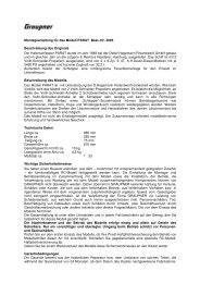
Klemmenbelegung im Schalt-Modus:KlemmeBelegung1 Versorgungsspannung -2 Versorgungsspannung + (6 - 14V DC)3 Eingang 14 Eingang 25 Ausgang 16 Ausgang 2DIP-Schalter Belegung im Schalt-Modus:S1 OFF ON1 Schalt-Modus aktiv -2 Schaltausgang 1 ohne Sanftanlauf Schaltausgang 1 mit Sanftanlauf (1s)3 Schaltausgang 2 ohne Sanftanlauf Schaltausgang 2 mit Sanftanlauf (1s)4 Memory- Funktion aus Memory- Funktion einAnschlussplan Schalt-Modus:MbraunorangeSoundswitch 1SchaltmodulSpannungsversorgung6 - 14V DC+ -Motor-ModusIm Motor-Modus kann 1 Motor angeschlossen werden, dieser kann in beideRichtungen betrieben werden. Über den 1. Eingang kann der Motor nach links, überden 2. Eingang nach rechts laufengelassen werden. Werden beide Eingängegleichzeitig eingeschaltet, passiert nichts, da diese gegeneinander verriegelt sind.Das Schaltmodul hat außerdem eine inte<strong>gr</strong>ierte Drehrichtungsumkehrsperre von 0,5oder 1 Sekunden. D.h. der Motor kann nicht schlagartig von Rechts- auf Linkslauf(bzw. umgekehrt) umgeschaltet werden.Zum schonenden Einschalten des Motors, verfügt das Schaltmodul über einenwählbaren Sanftanlauf von 0,5 oder 2 Sekunden.Also Option kann noch eine Bremsfunktion zugeschaltet werden. Der Motor wirddann beim Abschalten 5 Sekunden lang, elektronisch abgebremst. Damit kann ein zulanger Auslauf verhindert werden.GRAUPNER GmbH & Co. KG D-73230 KIRCHHEIM/TECK GERMANYKeine Haftung für Druckfehler. Technische Änderungen vorbehalten! #0061023 11/2009
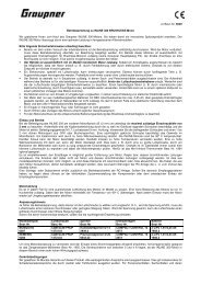
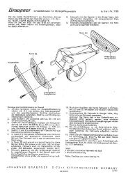
Klemmenbelegung im Motor-Modus:KlemmeBelegung1 Versorgungsspannung -2 Versorgungsspannung + (6 - 14V DC)3 Eingang Rechtslauf4 Eingang Linkslauf5 Motor +6 Motor -DIP-Schalter Belegung im Motor-Modus:S1 OFF ON1 - Motor-Modus aktiv2 langsamer Sanftanlauf (2s) schneller Sanftanlauf (0,5s)3 langsame Umschaltzeit re/li (1s) schnelle Umschaltzeit re/li (0,5s)4 Bremsfunktion aus Bremsfunktion einAnschlussplan Motor-ModusEndschalter(Option)MbraunorangeSoundswitch 1SchaltmodulSpannungsversorgung6 - 14V DC+ -Anschluss von Endschaltern:Bei vielen Anwendungen wie z.B. einer Steuerung für eine Ankerkette, einemDrehkran usw., ist es erforderlich die Bewegung auf einen bestimmten Bereich zube<strong>gr</strong>enzen. Dies kann bei dem Schaltmodul einfach gelöst werden, indemEndschalter mit einem Öffner-Kontakt (n.c.), in die Steuerleitung geschaltet werden.Der jeweilige Endschalter muss dann mechanisch betätigt werden, wenn dieBewegung gestoppt werden soll.GRAUPNER GmbH & Co. KG D-73230 KIRCHHEIM/TECK GERMANYKeine Haftung für Druckfehler. Technische Änderungen vorbehalten! #0061023 11/2009
Technische DatenVersorgungsspannung (U b ): 6 – 14V GleichspannungStromaufnahme:Ruhestrom: ca. 4mASchalt-Eingänge:2 Stück minusschaltendInte<strong>gr</strong>ierte Pull-Up-Widerstände (4k7)Schalt-Ausgänge:Schalt-Modus: 2 Ausgänge, Dauerstrom 2 x7A, kurzzeitig max. 10A, offener Collector(npn)Motor-Modus: 1 Ausgang für 1 Motor mitRechts- und Linkslauf, Dauerstrom 5A,kurzzeitig max. 10ASanftanlauf:Schalt-Modus: 0s oder 1sMotor-Modus: 0,5s oder 2sDrehrichtungsumkehrsperre: 0,5s oder 1sÜberstromabschaltung:Elektronische Überstromabschaltung bei ca.20AUnterspannungsabschaltung: Bei einer Versorgungsspannung < 5,3VZulässige Umgebungstemperatur: 0 – 60°CZulässige relative Luftfeuchte: Max. 85%Abmessung:69 x 30 x 10 mmGewicht:15gViel Spaß mit Ihrem neuen Schaltmodul wünscht Ihnendas Graupner TeamInstructions for Switching Module,Order No.: <strong>3755</strong>Manufacturer’s declaration from Graupner GmbH & Co. KGIf material defects or manufacturing faults should arise in a product distributed by us in theFederal Republic of Germany and purchased by a consumer (§ 13 BGB), we, GraupnerGmbH & Co. KG, D-73230 Kirchheim/Teck, Germany, acknowledge the obligation to correctthose defects within the limitations described below.The consumer is not entitled to exploit this manufacturer’s declaration if the failure in theusability of the product is due to natural wear, use under competition conditions, incompetentor improper use (including incorrect installation) or external influences.This manufacturer’s declaration does not affect the consumer’s legal or contractual rightsregarding defects arising from the purchase contract between the consumer and the vendor(dealer).Extent of the guaranteeIf a claim is made under guarantee, we undertake at our discretion to repair or replace thedefective goods. We will not consider supplementary claims, especially for reimbursement ofcosts relating to the defect (e.g. installation / removal costs) and compensation forconsequent damages unless they are allowed by statute. This does not affect claims basedon legal regulations, especially according to product liability law.GRAUPNER GmbH & Co. KG D-73230 KIRCHHEIM/TECK GERMANYNo liability for printing errors. Technical modifications reserved. #0061023 11/2009
Guarantee requirementsThe purchaser is required to make the guarantee claim in writing, and must enclose originalproof of purchase (e.g. invoice, receipt, delivery note) and this guarantee card. He must sendthe defective goods to us at his own cost, using the following address:Graupner Service UKBrunel DriveGB Newark, Nottinghamshire NG242EGThe purchaser should state the material defect or manufacturing fault, or the symptoms ofthe fault, in as accurate a manner as possible, so that we can check if our guaranteeobligation is applicable.The goods are transported from the consumer to us and from us to the consumer at the riskof the consumer.Duration of validityThis declaration only applies to claims made to us during the claim period as stated in thisdeclaration. The claim period is 24 months from the date of purchase of the product by theconsumer from a dealer in the Federal Republic of Germany (date of purchase). If a defectarises after the end of the claim period, or if the evidence or documents required according tothis declaration in order to make the claim valid are not presented until after this period, thenthe consumer forfeits any rights or claims from this declaration.Limitation by lapse of timeIf we do not acknowledge the validity of a claim based on this declaration within the claimperiod, all claims based on this declaration are barred by the statute of limitations after sixmonths from the time of implementation; however, this cannot occur before the end of theclaim period.Applicable lawThis declaration, and the claims, rights and obligations arising from it, are based exclusivelyon the pertinent German Law, without the norms of international private law, and excludingUN retail law.Important safety notesYou have acquired a switching module which can be used as part of the equipment for aworking radio-controlled model. However, we as manufacturers have no control over the wayyou build and operate your RC model, nor how you install, operate and maintain theassociated components, and for this reason we are obliged to deny all liability for loss,damage or costs which are incurred due to the incorrect use of our products or due toincompetent behaviour on the part of the user, or which are connected with such operation inany way. Unless otherwise prescribed by binding law, the obligation of the GRAUPNERcompany to pay compensation, regardless of the legal argument employed, is excluded. Thisincludes personal injury, death, damage to buildings, damages due to loss of business orturnover, interruption of business or other direct or indirect consequent damage whose rootcause was the operation of the model.The total liability in all cases and under all circumstances is limited to the amount of moneywhich you actually paid for the model.The model is operated at the sole and express responsibility of the operator. The onlyway to avoid injury to persons and damage to property is to handle and operate themodel with the <strong>gr</strong>eatest care and consideration at all times.Before you use the switching module for the first time, please check that your private thirdpartyinsurance policy covers you for operating model boats of this type. If you are not sureGRAUPNER GmbH & Co. KG D-73230 KIRCHHEIM/TECK GERMANYNo liability for printing errors. Technical modifications reserved. #0061023 11/2009
about this, it is best to take out a special insurance covering the operation of RC models.These safety notes must be kept in a safe place. If you ever dispose of the module, be sureto pass them on to the new owner.The following points are important, and must be observed at all times:• The switching module is not suitable for use by children below fourteen years of age.• Before you run the model, it is important to check that the radio control system isoperating correctly, and that all plug-in connectors are firmly seated.• Check that your channel is not already in use. Never switch your system on if you are notcertain that your channel is free.• Bear in mind that other radio equipment and public service transmitters are potentialsources of powerful interference. As far as possible, ensure that no apparatus of this kindis in use while you operate your model.• Never exceed the recommended operating voltage. Higher voltages may damage or ruinyour module and model.• Do not subject the switching module to severe humidity, heat, cold or soiling.• Take particular care to keep your model watertight. Open the model after each run, andallow it to dry out naturally.Care and maintenance• If water gets inside the boat, open the hatch to allow it to escape. If water shouldpenetrate the case of the switching module, dry it out thoroughly before sending it to yournearest GRAUPNER Service Centre for checking.• An effective preventative measure to avoid damp problems is to spray the module usingWET.PROTECT, Order No. 968.50.Safety notes• Read right through these operating instructions before you use the module for the firsttime, and keep them in a safe place in case you need to consult them in future.• The switching module’s inte<strong>gr</strong>ated circuits are sensitive to electro-static charge. Take<strong>gr</strong>eat care not to touch these components unless you have “discharged” yourselfbeforehand (e.g. by <strong>gr</strong>asping a central heating radiator or other earthed device).• The switching module must only be used in conjunction with a power supply withinthe voltage range stated in the Specification.• The unit must be disconnected from the power supply before any electricalconnections are made.• This switching module is not suitable for use by children under fourteen years of age.Operating InstructionsFunctionsThe purpose of the switching module is to switch high-current consumer units (e.g.motors, lamps, pumps, etc.) drawing a maximum current of 10 A. It can also be usedin circuits where, for example, the current-handling capacity of an existing switchmodule is not sufficient for the consumer unit you wish to control.The switching module is generally controlled using the outputs of a Soundswitch 1 orthe outputs of a Light module. The two inputs of the module are negative-switching,i.e. the switch module connected to it must also have negative-switching outputs.The switching module features two modes of operation: “switching mode” and “motormode”. In Switching mode it is possible to switch two consumer units on and offGRAUPNER GmbH & Co. KG D-73230 KIRCHHEIM/TECK GERMANYNo liability for printing errors. Technical modifications reserved. #0061023 11/2009
individually. In Motor mode the unit can control one motor in both directions ofrotation.If the switching module is powered by a separate battery, then the negative terminalof that battery must be connected to the negative terminal of the battery connected tothe Sound module or Light module.Excess-current cut-off:If the current flowing at the outputs rises to more than about 20 A, the excess currenttriggers the unit’s electronic cut-off circuit. The two outputs are then switched off, andthe blue LED starts to flash. To reset the switching module, simply disconnect itbriefly from its power supply.Low-voltage cut-off:If the power supply voltage falls below 5.3 V, the outputs are also switched off. If thisstate occurs, the blue LED lights up.Switching modeIn switching mode each input can be used to switch one consumer unit on and off,i.e. one switching module can control two consumer units. A one-second soft-startcan be activated in order to avoid premature wear of the consumer unit.As an option a memory function can also be activated for the two outputs: in thismode the first time you activate the input, the output is switched on; the second timeit is activated, the output is switched off again.Terminal assignment in Switching mode:TerminalAssignment1 Power supply voltage -2 Power supply voltage + (6 - 14 V DC)3 Input 14 Input 25 Output 16 Output 2DIP-switch assignment in Switching mode:S1 OFF ON1 Switching mode active -2 Switched output 1 without soft-start Switched output 1 with soft-start (1 s)3 Switched output 2 without soft-start Switched output 2 with soft-start (1 s)4 Memory function off Memory function onWiring dia<strong>gr</strong>am, switching mode:GRAUPNER GmbH & Co. KG D-73230 KIRCHHEIM/TECK GERMANYNo liability for printing errors. Technical modifications reserved. #0061023 11/2009
MbrownorangeSoundswitch 1Switching modulePower supply6 - 14V DC+ -Motor modeIn Motor mode the module is connected to one motor, which can then be operated inboth directions of rotation. The first input is used to run the motor in the left-handdirection, the second input in the right-hand direction. If both inputs are switched onsimultaneously, nothing happens, as they are interlocked. The switching module alsofeatures an inte<strong>gr</strong>al block on direction reversing, with a duration of 0.5 or 1 second,i.e. the motor cannot be switched abruptly from right-hand to left-hand rotation (orvice versa).To avoid premature motor wear, the switching module features a selectable soft-startwith a duration of 0.5 or 2 seconds.An optional brake function can also be activated: in this case the motor is brakedelectronically for a period of five seconds after it is switched off. The purpose of thisfeature is to prevent the model coming to a halt too slowly.Terminal assignment in Motor mode:TerminalAssignment1 Power supply voltage -2 Power supply voltage + (6 - 14V DC)3 Input, right-hand rotation4 Input, left-hand rotation5 Motor +6 Motor -DIP-switch assignment in Motor mode:S1 OFF ON1 - Motor mode active2 Slow soft-start (2 s) Fast soft-start (0.5 s)3 Slow transition, right / left (1 s) Fast transition, right / left (0.5 s)4 Brake function off Brake function onGRAUPNER GmbH & Co. KG D-73230 KIRCHHEIM/TECK GERMANYNo liability for printing errors. Technical modifications reserved. #0061023 11/2009
Wiring dia<strong>gr</strong>am, Motor mode:End-point switch(optional)MbrownorangeSoundswitch 1Switching modulePower supply6 - 14V DC+ -Connecting end-point switches:For many applications, such as controlling anchor chains, swivelling cranes, etc., it isnecessary to limit the travel at a particular point. With the switching module this is easy toimplement by wiring an end-point switch with normally closed (n.c.) contacts in the controlcable. The end-point switch must then be actuated mechanically at the point where themovement is required to cease.SpecificationPower supply voltage (U b ):6 – 14 V D.C. voltageCurrent drain:Idle current: approx. 4 mASwitching inputs:Two inputs, negative switchingInte<strong>gr</strong>ated Pull-Up resistors (4k7)Switching outputs:Switching mode: Two outputs, continuouscurrent 2 x 7 A, peak max. 10 A, open Collector(npn)Motor mode: One output for one motor with righthandand left-hand rotation, continuous current 5A, peak max. 10ASoft-start:Switching mode: 0 s or 1 sMotor mode: 0.5 s or 2 sDirection of rotation block:0.5 s or 1 sExcess-current cut-off:Electronic excess current cut-off at around 20 ALow-voltage cut-off:At a power supply voltage < 5.3 VPermissible ambient temperature: 0 – 60°CPermissible relative humidity: Max. 85%Dimensions:69 x 30 x 10 mmWeight:15 gWe all wish you loads of fun with your switching module.Best wishes - the Graupner TeamGRAUPNER GmbH & Co. KG D-73230 KIRCHHEIM/TECK GERMANYNo liability for printing errors. Technical modifications reserved. #0061023 11/2009
Instructions pour le module de commutation,Réf. N° <strong>3755</strong>Déclaration du fabricant de la Firme Graupner GmbH & Co KGContenu de la déclaration :Lorsqu’un article que nous distribuons dans la République Fédérale d’Allemagne acquis par unconsommateur (§ 13 BGB) présente un défaut de matière ou de fabrication, nous la Firme GraupnerGmbH & Co. KG, Kirchheim Teck, prenons en charge la suppression du défaut de l’article dans lesconditions ci après.Le consommateur ne peut pas valider le droit de déclaration du fabricant lorsque le défaut de l’articleprovient d’une usure naturelle, d’une utilisation dans des conditions de compétition, d’une mauvaiseutilisation (incluant le montage) ou d’influences extérieures.Cette déclaration du fabricant laisse inchangés le droit et les réclamations légales ou contractuelles duconsommateur provenant du contrat d’achat vis à vis de son vendeur (le détaillant).Conseils de sécurité importantsVous avez fait l’acquisition d’un module de commutation avec les accessoires adaptéscorrespondants qui vont vous permettre, la réalisation d’un modèle R/C fonctionnel. Lerespect des instructions de montage et d'utilisation relatives au modèle ainsi quel'installation, l'utilisation et l'entretien des éléments de son équipement ne peuvent pas êtresurveillés par la Firme GRAUPNER. C'est pourquoi nous déclinons toute responsabilitéconcernent les pertes, les dommages ou les coûts résultants d'une mauvaise utilisation oud'un fonctionnement défectueux. Tant qu'elle n'y a pas été contrainte par le législateur, laresponsabilité de la Firme GRAUPNER n'est aucunement engagée pour lesdédommagements (incluant les dégâts personnels, les cas de décès, la détérioration debâtiments ainsi que le remboursement des pertes commerciales dues à une interruptiond'activité ou à la suite d'autres conséquences directes ou indirectes) provenant de l'utilisationdu modèle. L'ensemble de sa responsabilité est en toutes circonstances et dans chaque casstrictement limité au montant que vous avez réellement payé pour ce modèle.La mise en service et l’utilisation du module de commutation se font uniquement auxrisques et périls de son utilisateur. Seule une utilisation prudente et responsableévitera de causer des dégâts personnels et matériels.Avant la première utilisation du module de commutation, vérifiez si votre assurancepersonnelle couvre ce genre de risques. Contractez le cas échéant une assurance spécialepour l'utilisation des modèles réduits radiocommandés.Ces conseils de sécurité devront absolument être conservés et remis à l’acheteur en cas derevente du module de commutation.Les points suivants devront absolument être observés : Le module de commutation ne convient pas aux enfants en dessous de 14 ans. Vérifiez la sécurité de fonctionnement de l’ensemble R/C avant l’utilisation du modèle,ainsi que le branchement correct et ferme de tous les connecteurs. Vérifiez si le canal de fréquence que vous utilisez est libre, ne faites pas naviguer votremodèle tant que vous n’êtes pas sûr qu’il n’est pas déjà utilisé. Notez que des appareils radio ou d’autres émetteurs peuvent fortement perturber lesfonctions de votre modèle. Veillez autant que possible à ce qu’aucun de ces appareils setrouvent à proximité pendant que vous faites naviguer votre modèle. La tension d’alimentation conseillée ne devra pas être dépassée. Une tension plusélevée peut conduire à la destruction du module de commutation. Ne soumettez pas le module de commutation à une forte humidité de l’air, à une chaleurou un froid intensifs, ainsi qu’aux salissures. Veillez particulièrement à l’étanchéité du modèle ; laissez le bien sécher après chaque
utilisation.Entretien Evacuez l’eau qui se serait éventuellement infiltrée en retirant le recouvrement. Si del’eau a pénétré dans le module de commutation, laissez le bien sécher et retournez le auS.A.V. GRAUPNER concerné pour contrôle. Une protection efficace contre l’humidité consiste à vaporiser le module avec le produitWET.PROTECT, Réf. N° 968.50.Ces instructions d’utilisation devront être attentivement lues avant de commencer la miseen service et soigneusement conservées pour une utilisation ultérieure.Les circuits inté<strong>gr</strong>és dans le module de commutation sont sensibles aux chargesélectrostatiques. Pour cette raison, ne touchez pas cet élément avant de l’avoir‘’déchargé’’ (Par ex. par une saisie sur un radiateur ou un autre appareil avec prise deterre).Le câblage devra être effectué uniquement sans tension.La mise en service du module de commutation n’est pas adaptée pour les enfants endessous de 14 ans.Instructions d’utilisationFonctionsAvec le module de commutation, des consommateurs (Par ex. moteurs, lampes,pompes, etc…) avec une forte consommation (jusqu’à 10A) pourront être commutés.Ceci pourra aussi être utilisé lorsque par ex. le courant d’un module de commutationexistant ne suffit pas pour le consommateur connecté.La commande du module de commutation se fait généralement par la sortie d’unSoundswitch 1 ou par celle du module de lumière. Les deux entrées du module decommutation sont commutées moins, ce qui signifie que le module de commutationrelié devra avoir des sorties commutées moins.Le module de commutation dispose de 2 genres d’exploitation ; en modecommutation et en mode moteur. En mode commutation, 2 consommateurs pourrontêtre commutés séparément. En mode moteur, 1 moteur pourra être commandé dansles deux sens de rotation.Si le module de commutation est alimenté par un accu séparé, le pôle moins de cetaccu devra être relié au pôle moins de l’accu du module de son ou de lumière.Coupure en sur courant :Si un courant de plus de 20A s’écoule des sorties, l’électronique de coupure en surcourant intervient. Les deux sorties seront ensuite décommutées et le LED bleucommencera à clignoter. Pour différer cet état, le module de commutation devra êtrebrièvement séparé de la tension d’alimentation.Coupure en sous tension :Si la tension d’alimentation chute en dessous d’une valeur de 5,3V, les sorties serontde même décommutées. Dans ce cas, le LED bleu sera alluméMode commutationDans le mode commutation avec les deux entrées, chaque consommateur pourraêtre commuté ou décommuté. Deux consommateurs pourront ainsi être commutés
avec un module de commutation. Pour ménager la commutation desconsommateurs, un démarrage souple de 1 seconde pourra être activé.Une fonction Mémoire en option pourra encore être commutée pour les deux sorties.Avec les premières activations des entrées, les sorties seront activées et ensuite ànouveau avec les prochaines activations.Occupation des bornes dans le mode commutation :BorneOccupation1 Tension d’alimentation -2 Tension d’alimentation + (6 - 14V DC)3 Entrée 14 Entrée 25 Sortie 16 Sortie 2Occupation dans le mode commutation DIP :S1 COUPE CONTACT1 Mode commutation activé -2 Sortie 1 sans démarrage souple Sortie 1 avec démarrage souple (1s)3 Sortie 2 sans démarrage souple Sortie 2 avec démarrage souple (1s)4 Fonction Mémoire coupée Fonction Mémoire en contactSchéma de câblage en mode commutationMbrunorangeSoundswitch 1Module de commutationTension d’alimentation6 - 14V DC+ -Mode MoteurDans le mode Moteur, 1 moteur pourra être relié et commandé dans les deux sensde rotation. Par l’entrée 1, le moteur pourra tourner vers la gauche et par l’entrée 2vers la droite. Si les deux entrées sont commutées simultanément, il ne se passerarien, car celles-ci sont verrouillées entre elles. Le module de commutation dispose enoutre d’un verrouillage d’inversion du sens de rotation inté<strong>gr</strong>é de 0,5 ou de 1seconde. C'est-à-dire que le moteur ne pourra pas être commuté brutalement dusens de rotation vers la droite sur le sens de rotation vers la gauche (et inversement).
Pour ménager la commutation du moteur, le module de commutation dispose d’undémarrage souple sélectionnable de 0,5 ou de 2 secondes.Une fonction de frein en option pourra encore être commutée. Le moteur sera ainsifreiné électroniquement par une coupure d’une longueur de 5 secondes ; une troplongue rotation sera ainsi empêchée.Occupation des bornes dans le mode moteur :BorneOccupation1 Tension d’alimentation -2 Tension d’alimentation (6 - 14V DC)3 Entrée rotation à droite4 Entrée rotation à gauche5 Moteur +6 Moteur -Occupation dans le mode Moteur DIP :S1 COUPE COINTACT1 - Moder Moteur activé2 Démarrage souple lent (2s) Démarrage souple rapide (0,5s)3 Temps de commutation lent d/g (1s) Temps de commutation rapide d/g(0,5s)4 Fonction de frein coupée Fonction de frein en contactSchéma de câblage en mode Moteur :Inter de finde courseMbrun(optional)orangeSoundswitch 1Module de commutationTension d’alimentation6 - 14V DC+ -Raccordement d’un Inter de fin de courseDans de nombreuses applications, comme par ex. la commande d’une chaîned’ancre, d’une <strong>gr</strong>ue rotative, etc… il est nécessaire de limiter le mouvement sur uneplage déterminée. Ceci pourra être facilement solutionné avec le module decommutation en interposant un inter de fin de course avec un ouvre contact (n.c.)
dans le circuit de commande. Chaque position finale devra ensuite être actionnéemécaniquement, lorsque le mouvement devra être stoppé.Caractéristiques techniques :Tension d’alimentation (U b ):Consommation en courant:Entrées de commutation:Sorties de commutation:Démarrage souple:Verrouillage d’inversion du sensde rotation:Coupure en sur courant:6 – 14V continuCourant au repos, env. 4mA2 Pièces commutées moinsRésistance inté<strong>gr</strong>ée Pull-Up (4k7)Mode commutation : 2 sorties, courantpermanent 2 x 7A, temporaire max. 10A,Mode moteur : 1 sortie pour 1 moteur à sensde rotation droite/gauche, courantpermanent 5A, temporaire max. 10AMode commutation: 0s ou 1sMode Moteur : 0,5s ou 2s0,5s our 1sCoupure électronique en sur courant avecenv. 20ACoupure en sous tension: Avec une tension d’alimentation de < 5,3VTempérature ambiante admissible: 0 – 60°CHumidité de l’air relativement Max. 85%admissible:Dimensions:69 x 30 x 10 mmPoids:15gNous vous souhaitons beaucoup de plaisir avec votre nouveau module decommutation !Votre équipe Graupner