capacitors for power electronics - GvA Leistungselektronik GmbH
capacitors for power electronics - GvA Leistungselektronik GmbH
capacitors for power electronics - GvA Leistungselektronik GmbH

Erfolgreiche ePaper selbst erstellen
Machen Sie aus Ihren PDF Publikationen ein blätterbares Flipbook mit unserer einzigartigen Google optimierten e-Paper Software.
APPLICATION NOTES_ANWENDUNGSBEISPIELE_AC<br />
76<br />
5<br />
6<br />
For non-symmetric voltages, Û has to be defi ned as (U 1 +U 2 )/2*.<br />
In our example, the <strong>power</strong> dissipation factor is<br />
P V = P VD + P VR = 0.85 W + 2.59 W = 3.44 W **.<br />
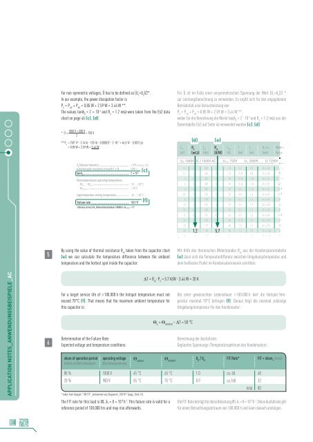
The values tan� 0 = 2 x 10 -4 and R S = 1.2 m� were taken from the E62 data<br />
chart on page 46 (c), (d).<br />
* Û =<br />
1000 V + 500 V<br />
= 750 V<br />
2<br />
** P V = 750 2 V 2 � 3.1416 � 120 Hz � 0.00002F � 2�10 -4 + 46.5 2 A 2 � 0.0012 �<br />
= 0.85 W + 2.59 W = 3.44 W<br />
C Toleranz tolerance N ±10% (optional ±5%)<br />
Isolationsgüte insulation strength C x Ris 5000 s<br />
2 x10⁻⁴ (c)<br />
tan� 0<br />
Grenztemperaturen operating temperatures<br />
�min ... �max -25 ... +85°C<br />
�HOTSPOT � 85°C<br />
Lagertemperatur storing temperature -40 ... +85°C<br />
Failure rate 100 FIT<br />
reference service life_Referenzbetriebsdauer 100000 h, �HOTSPOT �70°<br />
By using the value of thermal resistance R th taken from the capacitor chart<br />
(e) we can calculate the temperature difference between the ambient<br />
temperature and the hottest spot inside the capacitor:<br />
For a target service life of � 100.000 h the hotspot temperature must not<br />
exceed 70°C (f). That means that the maximum ambient temperature <strong>for</strong><br />
this capacitor is:<br />
Determination of the Failure Rate:<br />
Expected voltage and temperature conditions:<br />
share of operation period<br />
Anteil an Betriebsdauer<br />
operating voltage<br />
Betriebsspannung<br />
� ambient<br />
�T = R th � P V = 5.7 K/W � 3.44 W = 20 K<br />
� U = � HOTSPOT – �T = 50 °C<br />
� HOTSPOT<br />
Für Û ist im Falle einer unsymmetrischen Spannung der Wert (U 1 +U 2 )/2 *<br />
zur Leistungsberechnung zu verwenden. Es ergibt sich für den angegebenen<br />
Betriebsfall eine Verlustleistung von<br />
P V = P VD + P VR = 0.85 W + 2.59 W = 3.44 W **,<br />
wobei für die Berechnung die Werte tan� 0 = 2 � 10 -4 und R S = 1.2 m� aus der<br />
Datentabelle E62 auf Seite 46 verwendet wurden (c), (d).<br />
(d) (e)<br />
CN R f<br />
S<br />
res R I Î I D x L Maßbild m<br />
th<br />
max S 1 1<br />
(µF) (m�) (kHz) (K/W) (A) (kA) (kA) (mm) Design (<br />
UN 1680V DC / 1000V AC Urms 720V US 2500V Ui 1250V UBB<br />
1.5 5.3 530 26 10 0.3 0.9 30 x 58 E11) / E4 0<br />
2.2 4.6 440 22 16 0.25 0.8 35 x 58 E2 0<br />
3 6.9 320 18 10 0.35 1.05 30 x 81 E11) / E4 0<br />
4 5.6 280 16 10 0.45 1.35 35 x 81 E2 1) 0<br />
5 4.8 250 14 20 0.6 1.8 40 x 81 D1 1) 0<br />
6.8 3.9 220 12 20 0.8 2.4 45 x 81 D1 1) 0<br />
8 4.4 170 12 16 0.5 1.4 45 x 85 B1 0<br />
10 3.8 159 10 32 0.6 1.7 50 x 85 G1 0<br />
12 5.9 139 10 16 0.7 2.1 55 x 85 B1 0<br />
15 5.5 124 8.7 16 0.9 2.6 60 x 85 D1 1) 0<br />
16 3.6 120 7.2 40 0.95 2.9 65 x 95 G1 0<br />
18 2.7 119 7.2 40 1.0 3.1 65 x 95 G1 0<br />
20 1.2 1.7 95 5.7 50 1.2 3.5 75 x 105 C2 0<br />
28 1.3 80 5.0 50 1.6 4.9 85 x 105 C2 0<br />
Mit Hilfe des thermischen Widerstandes R th aus der Kondensatorentabelle<br />
(e) lässt sich die Temperaturdifferenz zwischen Umgebungstemperatur und<br />
dem heißesten Punkt im Kondensatorinneren ermitteln.<br />
Bei einer gewünschten Lebensdauer � 100.000 h darf die Hotspot-Temperatur<br />
maximal 70°C betragen (f). Daraus folgt die maximal zulässige<br />
Umgebungstemperatur für den Kondensator:<br />
Berechnung der Ausfallrate:<br />
Geplantes Spannungs-/Temperaturspektrum des Kondensators:<br />
U B / U N FIT Rate* FIT × share_Anteil<br />
80 % 1000 V 45 °C 65 °C 1.0 ca. 60 48<br />
20 % 900 V 55 °C 75 °C 0.9 ca.160 32<br />
total 80<br />
* taken from diagram “100 FIT”_entnommen aus Diagramm „100 FIT” (page_Seite 14)<br />
The FIT rate <strong>for</strong> this load is 80, � = 8 × 10 -8 h -1 . This failure rate is vaild <strong>for</strong> a<br />
reference period of 100.000 hrs and may rise afterwards.<br />
(f)<br />
Die FIT-Rate beträgt für diese Belastung 80, � = 8 × 10 -8 h -1 . Diese Ausfallrate gilt<br />
für einen Betrachtungszeitraum von 100.000 h und kann danach ansteigen.