capacitors for power electronics - GvA Leistungselektronik GmbH
capacitors for power electronics - GvA Leistungselektronik GmbH
capacitors for power electronics - GvA Leistungselektronik GmbH

Sie wollen auch ein ePaper? Erhöhen Sie die Reichweite Ihrer Titel.
YUMPU macht aus Druck-PDFs automatisch weboptimierte ePaper, die Google liebt.
APPLICATION NOTES_ANWENDUNGSBEISPIELE_DC<br />
78<br />
2<br />
3<br />
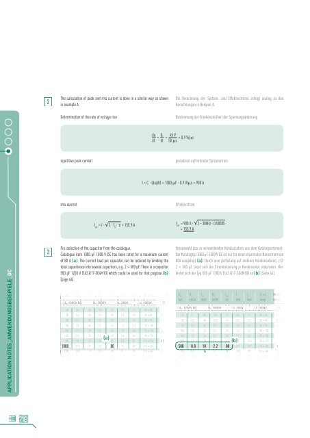
The calculation of peak and rms current is done in a similar way as shown<br />
in example A.<br />
Determination of the rate of voltage rise<br />
repetitive peak current<br />
rms current<br />
I eff = î � �2 � f 0 �� = 155.9 A<br />
Pre-selection of the capacitor from the catalogue:<br />
Catalogue item 1000 µF 1000 V DC has been rated <strong>for</strong> a maximum current<br />
of 80 A (a). The current load per capacitor can be reduced by dividing the<br />
total capacitance into several <strong>capacitors</strong>, e.g. 2 x 500 µF. There is a capacitor<br />
500 µF 1200 V (E63.R17-504M10) which could be used <strong>for</strong> that purpose (b)<br />
(page 64).<br />
800 1.8 16 3.3 43 7.3 20 100 x 176 L1<br />
UN 1000V DC US 1500V Ur 200V Ui 1000V UBB<br />
60 3.6 65 13.5 25 0.7 2.1 50 x 85 G1<br />
80 4.6 63 12.3 20 0.9 2.8 55 x 85 D1<br />
100 4.2 50 9.8 28 1.1 3.4 65 x 95 G1<br />
150 2.3 36 7.3 43 1.7 5.2 75 x 105 L1<br />
250 2.1 28 5.7 43 2.9 8.6 95 x 105 L1<br />
470<br />
700<br />
2.0<br />
1.0<br />
20<br />
17<br />
3.4<br />
2.8<br />
43<br />
80<br />
5.4<br />
8.0<br />
16.1<br />
20<br />
95 x 176<br />
116 x 176<br />
L1<br />
M1<br />
1000 0.75 12 2.0 80 11 20 2) 116 x 245 C2<br />
1200 0.65 9 2.0 80 9 16 116 x 245 C2<br />
1500 0.6 10 1.7 80 15 2) 20 2) (a)<br />
136 x 245 C2<br />
du Ur 45 V<br />
= = = 0.9 V/�s<br />
dt dt 50 �s<br />
Die Berechnung des Spitzen- und Effektivstroms erfolgt analog zu den<br />
Berechnungen in Beispiel A.<br />
Bestimmung der Flankensteilheit der Spannungsänderung<br />
periodisch auftretender Spitzenstrom<br />
î = C � (du/dt) = 1000 �F � 0.9 V/�s = 900 A<br />
Effektivstrom<br />
I eff = 900 A � �2 � 300Hz � 0.00005<br />
= 155.9 A<br />
Vorauswahl des zu verwendenden Kondensators aus dem Katalogsortiment:<br />
Der Katalogtyp 1000 µF 1000 V DC ist nur für einen maximalen Nennstrom von<br />
80A ausgelegt (a). Durch eine Aufteilung auf mehrere Kondensatoren, z.B.<br />
2 x 500 µF, lässt sich die Strombelastung je Kondensator reduzieren. Hier<br />
bietet sich der Typ 500 µF 1200 V (E63.R17-504M10) an (b) (Seite 64).<br />
CN RS fres Rth Imax Î IS D x L 1 1 Maßbild<br />
(µF) (m�) (kHz) (K/W) (A) (kA) (kA) (mm) Design<br />
UN 1200V DC US 1800V Ur 280V Ui 1000V UBB<br />
40 5 80 13.5 22 0.6 1.7 50 x 85 G1<br />
50 6.3 68 12.3 16 0.7 2.1 55 x 85 B1<br />
75 3.5 58 9.8 32 1.0 3.1 65 x 95 G1<br />
100 1.5 43 6.4 43 1.4 4.1 85 x 105 L1<br />
160 1.3 34 5.7 43 2.2 6.6 95 x 105 L1<br />
300 0.9 23 3.4 43 4.1 12.4 95 x 176 L1<br />
500 0.8 18 2.2 80 6.9 20 2) 116 x 176 M1<br />
750 0.7 14 2.0 80 10.3 20 2) 116 x 245 C2<br />
1000 0.65 12 1.7 100 13.7 20 2) (b)<br />
136 x 245 C2