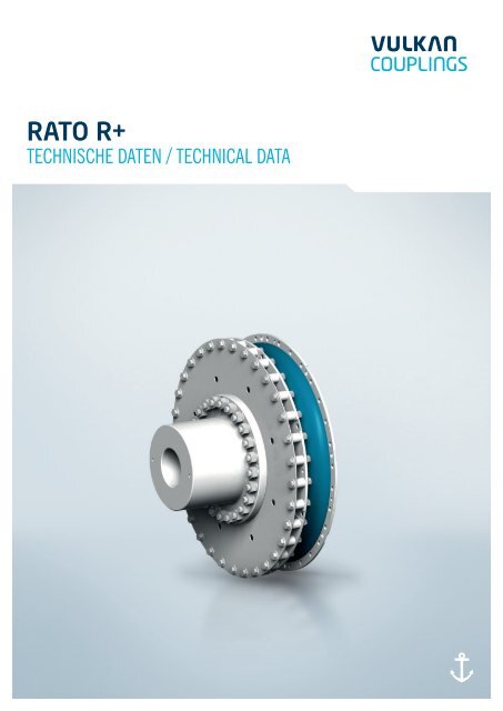
RATO R+ â Technical Data A4 (04.02.2013).indd - vulkan group
RATO R+ â Technical Data A4 (04.02.2013).indd - vulkan group
RATO R+ â Technical Data A4 (04.02.2013).indd - vulkan group

Erfolgreiche ePaper selbst erstellen
Machen Sie aus Ihren PDF Publikationen ein blätterbares Flipbook mit unserer einzigartigen Google optimierten e-Paper Software.
Baugröße Baugruppe NenndrehmomentMax.Drehmoment1Max.Drehmoment2Max. DrehmomentbereichZul. WechseldrehmomentZul.VerlustleistungZul. DrehzahlZul. axialerWellenversatzZul. radialerKupplungsversatzAxialeRückstellkraftRadialeFedersteifeDynamischeDrehfedersteifeVerhältnismäßigeDämpfungSizeDimensionGroupNorminalTorqueMax.Torque 1Max.Torque 2Max.TorqueRangePerm. VibratoryTorquePerm.PowerLossPerm.RotationalSpeedPerm. AxialShaft DisplacementPerm. RadialCouplingDisplacementAxialReactionForceRadialStiffnessDynamicTorsionalStiffnessRelativeDampingT KNkNmT Kmax1kNmT Kmax2kNm∆T maxkNmT KWkNmP KV50kWn Kmax2)1/min∆K amm∆K r ‘ 2)mmF ax für 0,1 x ∆KaC rdynkN/mmC Tdyn1) 2)kNm/radnominalψ 1)3)nominalIMPORTANT 1) : CTdyn warm, CTdyn la, ψ warm are to be considered!3B2S 3B20 66,5 100,0 300,0 75,0 17,00 1,20 1675 7,0 17,0 0,50 2,2 180 0,753B2M 3B20 70,0 105,0 315,0 84,0 17,50 1,20 1675 7,0 17,0 0,50 3,1 252 0,903B2H 3B20 80,0 120,0 360,0 100,5 20,00 1,20 1675 7,0 12,0 0,50 4,0 329 1,133C1S 3C10 83,0 125,0 374,0 95,0 21,00 0,62 1100 5,5 9,5 0,45 6,0 450 0,753C1M 3C10 90,0 135,0 405,0 97,0 22,50 0,62 1100 5,5 8,0 0,45 7,2 640 0,903C1H 3C10 100,0 150,0 450,0 116,5 25,00 0,62 1100 5,5 6,0 0,45 9,2 810 1,133C2S 3C20 83,0 125,0 374,0 95,0 21,00 1,24 1100 5,5 19,0 0,45 3,0 225 0,753C2M 3C20 90,0 135,0 405,0 97,0 22,50 1,24 1100 5,5 16,0 0,45 3,6 320 0,903C2H 3C20 100,0 150,0 450,0 116,5 25,00 1,24 1100 5,5 12,0 0,45 4,6 405 1,133E1S 3E10 100,0 150,0 450,0 121,5 25,00 0,84 1545 7,0 6,0 0,40 8,6 860 0,753E1M 3E10 110,0 165,0 495,0 142,5 27,50 0,84 1545 7,0 6,0 0,40 11,4 1200 0,903E1H 3E10 125,0 188,0 560,0 171,0 31,00 0,84 1545 7,0 4,4 0,40 12,6 1350 1,133E2S 3E20 100,0 150,0 450,0 121,5 25,00 1,68 1545 7,0 12,0 0,40 4,3 430 0,753E2M 3E20 110,0 165,0 495,0 142,5 27,50 1,68 1545 7,0 12,0 0,40 5,7 600 0,903E2H 3E20 125,0 188,0 560,0 171,0 31,00 1,68 1545 7,0 8,7 0,40 6,3 675 1,134A1S 4A10 137,0 205,0 616,0 190,0 34,00 0,80 900 9,0 10,8 0,85 5,8 800 0,754A1M 4A10 154,0 231,0 693,0 212,0 38,00 0,80 900 9,0 7,2 0,85 8,5 1150 0,904A1H 4A10 176,0 264,0 792,0 247,0 44,00 0,80 900 9,0 5,2 0,85 16,3 1500 1,134A2S 4A20 137,0 205,0 616,0 190,0 34,00 1,60 900 9,0 21,6 0,85 2,9 400 0,754A2M 4A20 154,0 231,0 693,0 212,0 38,00 1,60 900 9,0 14,4 0,85 4,3 575 0,904A2H 4A20 176,0 264,0 792,0 247,0 44,00 1,60 900 9,0 10,4 0,85 8,2 750 1,13Siehe Erläuterung der Technischen Daten.Andere Steifigkeiten auf Anfrage.1) VULKAN empfiehlt die zusätzliche Berücksichtigung von C Tdyn warm (0,7), C Tdyn la (1,35)und ψ warm (0,7) für die Berechnung der Drehschwingungen in der Anlage.2) Der Betriebszustand der Anlage kann eine Korrektur der gegebenen Werte notwendigmachen.Siehe Erläuterungen der Technischen Daten.Bei mehrreihigen Kupplungen müssen bei der Durchführung einer Drehschwingungsanalyseder Anlage die individuellen Massenträgheitsmomente der Kupplung und diedynamischen Drehfedersteifen der einzelnen Elemente berücksichtigt werden.Durch die Eigenschaft des Werkstoffs Gummi sind Toleranzen der aufgeführten Daten fürC Tdyn von ± 15% möglich.3) Bedingt durch die physikalischen Eigenschaften der elastischen Elemente sind Toleranzender aufgeführten Daten für ψ, von 0 % bis -30% für die W, T, Q, Y Elemente bzw., von 0 % bis-45% für die Z, J Elemente möglich.See Explanation of the <strong>Technical</strong> <strong>Data</strong>.Different stiffnesses on request.1) VULKAN recommend that the values C Tdyn warm (0.7), C Tdyn la (1.35) and ψ warm (0.7) beadditionally used when the installations of torsional vibrations are calculated.2) The actual operating condition could require the correction of the given values. See explanationof <strong>Technical</strong> <strong>Data</strong>.In case of multi-row couplings, the individual mass-moments of inertia and dynamictorsional stiffnesses of the coupling must be taken into consideration when making thetorsional vibration analysis of the installation.The properties of the rubber material mean that tolerances of ± 15 % with respect to thedata given for C Tdyn are possible.3) Because of the physical properties of the elastic elements, tolerances of 0 % to -30 % for theW, T, Q, Y elements and 0 % to -45 % for the Z and J elements with respect to the data givenfor ψ are possible.01/2013<strong>RATO</strong> <strong>R+</strong>07
Abmessungen/Massenträgheitsmomente/MassenDimensions/Mass-Moments of Inertia/Masses<strong>RATO</strong> <strong>R+</strong> Baureihe / Series 2200Baugruppe Abmessungen Massenträgheitsmoment Masse SchwerpunktsabstandDimensionGroupDimensions Mass moment of inertia Mass Distance to center of gravityT KN D 1 D 2 D 3 D 4 D 5 Z L kr T L 1 L 2 L 4 L 5 L 8 J 1 J 2 J 3 J 4 m 1 m 2 m 3 m 4 s 1 s 2 s 3 s 4maxkNm[kgm 2 ] [kg] [mm]vorgeb.pilot boredG2D10RG2D20RG2F10RG2F20RG2G10RG2G20RG3B10RG3B20RG3C10RG3C20RG3E10RG3E20RG4A10RG4A20R26,5 -31,534,0 -40,034,0 -40,034,0 -40,041,5 -51,041,5 -51,066,5 -80,066,5 -80,083,0 -100,083,0 -100,0100,0 -125,0100,0 -125,0137,0 -176,0137,0 -176,0685 110 170 15,5 – – 680 650 32 315,5 195,0 10,0 – – 2,0 3,3 – – 33,3 105,2 – – 24,5 149,0 – –685 110 170 15,5 – – 680 650 32 411,0 195,0 10,0 – – 2,0 2,5 4,4 – 33,0 39,0 122,0 – 25,0 317,0 166,0 –735 110 185 15,5 – – 730 700 32 357,9 225,0 10,0 – – 2,8 4,9 – – 40,0 142,0 – – 26,0 168,0 – –735 110 185 15,5 – – 730 700 32 463,0 225,0 10,0 – – 2,8 3,4 6,2 – 40,0 46,0 162,5 – 26,0 360,0 185,0 –793 100 200 17,5 – – 790 755 32 376,0 235,0 10,0 – – 3,9 7,3 – – 47,4 183,0 – – 28,0 174,0 – –793 100 200 17,5 – – 790 755 32 488,0 235,0 10,0 – – 3,9 4,9 9,1 – 47,4 56,0 207,0 – 28,0 378,0 191,0 –925 115 235 20,0 – – 920 880 32 452,2 285,0 12,0 – – 8,5 15,5 – – 77,0 295,0 – – 34,0 209,0 – –925 115 235 20,0 – – 920 880 32 586,0 285,0 12,0 – – 8,5 10,7 19,5 – 77,0 91,4 333,0 – 34,0 454,0 228,0 –1000 150 255 22,0 – – 995 950 32 497,5 300,0 12,5 – – 12,9 29,1 – – 96,0 403,0 – – 30,0 243,0 – –1000 150 255 22,0 – – 995 950 32 656,0 300,0 12,5 – – 12,9 28,3 29,1 – 100,0 203,0 404,0 – 31,0 500,0 243,0 –1078 160 275 24,0 39,0 1085,0 1070 1025 32 471,7 310,0 8,0 – – 29,2 39,3 – – 150,5 495,0 – – 50,0 228,0 – –1085 160 275 24,0 39,0 – 1070 1025 32 574,7 310,0 8,0 – – 29,2 21,3 48,2 – 150,5 127,0 564,0 – 50,0 428,0 244,0 –1250 200 320 26,0 – – 1240 1190 32 626,0 385,0 14,5 – – 38,4 83,7 – – 184,0 768,0 – – 36,0 307,0 – –1250 200 320 26,0 – 1240 1190 32 821,5 385,0 14,5 – – 38,5 82,9 84,0 – 190,0 385,0 770,0 – 37,0 628,0 307,0 –Maße in mmAlle Massen und Massenträgheitsmomente beziehen sich auf vorgebohrte Naben. Bei mehrreihigenKupplungen müssen bei der Durchführung einer Drehschwingungsanalyse der Anlage dieindividuellen Massenträgheitsmomente der Kupplung und die dynamischen Drehfedersteifender einzelnen Elemente berücksichtigt werden.Dimensions in mmAll masses and mass moments of inertia refer to pilot bored hubs. In case of multi-rowcouplings the individual mass-moments of inertia and dynamic torsional stiffnesses of thecoupling must be taken into consideration when making the torsional vibration analysis of theinstallation.08 <strong>RATO</strong> <strong>R+</strong>01/2013
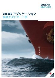
Abmessungen/Massenträgheitsmomente/MassenDimensions/Mass-Moments of Inertia/Masses<strong>RATO</strong> <strong>R+</strong> Baureihe / Series 2201Baugruppe Abmessungen Massenträgheitsmoment Masse SchwerpunktsabstandDimensionGroupDimensions Mass moment of inertia Mass Distance to center of gravityT KN D 1 D 2 D 3 D 4 D 5 Z L kr T L 1 L 2 L 4 L 5 L 8 J 1 J 2 J 3 J 4 m 1 m 2 m 3 m 4 s 1 s 2 s 3 s 4maxkNm[kgm 2 ] [kg] [mm]vorgeb.pilot boredG2D10RG2D20RG2F10RG2F20RG2G10RG2G20RG3B10RG3B20RG3C10R20,0 -25,025,0 -31,531,5 -40,050,0 -63,0Daten in Vorbereitung / <strong>Data</strong> in preparation685 110 170 15,5 – – 680 650 32 411,0 195,0 10,0 – – 2,1 2,5 4,4 – 40,0 38,0 129,0 – 30,0 317,0 171 –Daten in Vorbereitung / <strong>Data</strong> in preparation735 110 185 15,5 – – 730 700 32 463,0 225,0 10,0 – – 2,9 3,4 6,3 – 49,0 46,0 170,0 – 34,0 360,0 191 –Daten in Vorbereitung / <strong>Data</strong> in preparation793 100 200 17,5 – – 790 755 32 488,0 235,0 10,0 – – 4,1 4,8 9,3 – 59,0 56,0 216,0 – 36,0 378,0 197 –Daten in Vorbereitung / <strong>Data</strong> in preparation925 115 235 20,0 – – 920 880 32 586,0 285,0 12,0 – – 9,0 10,7 19,8 – 95,0 91,0 349,6 – 43,0 454,0 236 –Daten in Vorbereitung / <strong>Data</strong> in preparationG3C20RG3E10RG3E20RG4A10RG4A20R63,0 - 1000 150 255 22,0 – – 995 950 32 656,0 300,0 12,0 – – 13,7 28,1 29,9 – 128,0 202,0 432,0 – 43,0 500,0 255 –90,0Daten in Vorbereitung / <strong>Data</strong> in preparationDaten in Vorbereitung / <strong>Data</strong> in preparation100,0 - 1250 200 320 26,0 – – 1240 1190 32 674,0 385,0 14,5 – – 40,5 89,9 – – 238,0 855,0 – – 51,0 332,0 – –180,0137,0 - 1250 200 320 26,0 – – 1240 1190 32 821,5 385,0 14,5 – – 40,8 82,9 86,1 – 238,7 385,0 820,0 – 50,0 682,0 322 –176,0Maße in mmAlle Massen und Massenträgheitsmomente beziehen sich auf vorgebohrte Naben. Bei mehrreihigenKupplungen müssen bei der Durchführung einer Drehschwingungsanalyse der Anlage dieindividuellen Massenträgheitsmomente der Kupplung und die dynamischen Drehfedersteifender einzelnen Elemente berücksichtigt werden.Dimensions in mmAll masses and mass moments of inertia refer to pilot bored hubs. In case of multi-rowcouplings the individual mass-moments of inertia and dynamic torsional stiffnesses of thecoupling must be taken into consideration when making the torsional vibration analysis of theinstallation.10 <strong>RATO</strong> <strong>R+</strong>01/2013
<strong>RATO</strong> <strong>R+</strong> Baureihe / Series 2201G2D20R, G2F20R, G2G20R, G3B20RG3C10R, G4A10RG3C20R, G4A20R01/2013<strong>RATO</strong> <strong>R+</strong>11
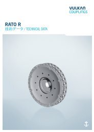
Abmessungen/Massenträgheitsmomente/MassenDimensions/Mass-Moments of Inertia/Masses<strong>RATO</strong> <strong>R+</strong> Baureihe / Series 2400Baugruppe Abmessungen Massenträgheitsmoment Masse SchwerpunktsabstandDimensionGroupDimensions Mass moment of inertia Mass Distance to center of gravityT KN D 1 D 2 D 3 D 5 L 1 L 2 L 3 L 6 J 1 J 2 J 3 J 4 m 1 m 2 m 3 m 4 s 1 s 2 s 3 s 4kNmvorgeb. max. [kgm 2 ] [kg] [mm]pilot boredG2D10RG2D20RG2F10RG2F20RG2G10RG2G20RG3B10RG3B20RG3C10RG3C20RG3E10RG3E20RG4A10RG4A20R26,5 -31,526,5 -31,534,0 -40,034,0 -40,041,5 -51,041,5 -51,066,5 -80,66,5 -80,083,0 -100,083,0 -100,0100,0 -125,0100,0 -125,0137,0 -176,0137,0 -176,0685 110 170 – 690,0 529,5 195,0 174,2 173,5 6,6 3,3 – – 155,5 105,2 – – 172,0 149,0 – –685 110 170 – 690,0 625,00 195,0 174,2 173,5 6,6 2,5 4,4 – 156,0 38,0 123,0 – 172,0 318,0 167,0 –735 110 185 – 740,0 601,0 225,0 203,2 202,5 8,9 4,9 – – 195,4 142,0 – – 190,0 168,0 – –735 110 185 – 740,0 706,0 225,0 203,2 202,5 8,9 3,4 6,2 – 195,4 46,0 162,5 – 190,0 360,0 185,0 –793 100 200 – 800,0 633,0 235,0 211,0 211,5 13,7 7,3 – – 256,0 183,0 – – 199,5 174,0 – –793 100 200 – 800,0 745,0 235,0 211,0 211,5 13,7 4,9 9,1 – 256,0 56,0 207,0 – 199,5 378,0 191,0 –925 115 235 – 935,0 758,0 285,0 256,5 252,5 28,0 15,5 – – 401,2 295,0 – – 237,0 209,0 – –925 115 235 – 935,0 892,0 285,0 256,5 252,5 28,0 10,7 19,5 – 401,2 91,4 333,0 – 237,0 454,0 228,0 –1000 150 255 – 1010,0 824,50 300,0 274,5 263,5 42,9 29,1 – – 498,0 403,0 – – 253,0 243,0 – –1000 150 255 – 1010,0 983,00 300,0 274,5 263,5 43,1 28,1 29,1 – 502,0 202,0 404,0 – 254,0 499,0 243,0 –1078 160 275 – 1085,0 736,7 310,0 271,5 255,0 57,5 39,3 – – 606,0 495,0 – – 239,0 228,0 – –1085 160 275 – – 839,7 310,0 271,0 255,0 57,5 21,3 48,2 – 606,0 127,0 564,0 – 239,0 428,0 244,0 –1250 200 320 – 1255,0 1041,00 385,0 355,0 348,5 121,7 83,5 – – 931,0 768,0 – – 320,0 307,0 – –1250 200 320 – 1255,0 1236,50 385,0 355,0 348,5 122,0 82,9 83,5 – 931,0 386,0 768,0 – 320,0 628,0 307,0 –Maße in mmAlle Massen und Massenträgheitsmomente beziehen sich auf vorgebohrte Naben. Bei mehrreihigenKupplungen müssen bei der Durchführung einer Drehschwingungsanalyse der Anlage dieindividuellen Massenträgheitsmomente der Kupplung und die dynamischen Drehfedersteifender einzelnen Elemente berücksichtigt werden.Dimensions in mmAll masses and mass moments of inertia refer to pilot bored hubs. In case of multi-rowcouplings the individual mass-moments of inertia and dynamic torsional stiffnesses of thecoupling must be taken into consideration when making the torsional vibration analysis of theinstallation.12 <strong>RATO</strong> <strong>R+</strong>01/2013
<strong>RATO</strong> <strong>R+</strong> Baureihe / Series 2400L3L1L6l1l3 l6d1d2vorgeb. maxpilot boredl2l2d2vorgeb. maxpilot boredd5m3m1S3S2m2S1G2D10R, G2F10R, G2G10R, G3B10RG2D20R, G2F20R, G2G20R, G3B20RL1L1L3L6L3L6D2 min.max.D2 min.max.D1D2 min.max.D2 min.max.min. D2max. D2min. D2max. D2D1L2L2D5M2M1S2S1L2L2D5D1L2L2D1M3M2M1S3M2M1S2S1S2S1G3E10RG3E20RG3C10R, G4A10RG3C20R, G4A20R01/2013<strong>RATO</strong> <strong>R+</strong>13
GültigkeitsklauselValidity ClauseDie vorliegende Broschüre ersetzt alle vorherigen Ausgaben, ältere Drucke verlierenihre Gültigkeit. VULKAN ist berechtigt, aufgrund neuerer Entwicklungen die indieser Broschüre enthaltenen Daten entsprechend anzupassen und zu verändern.Die neuen Daten gelten nur für nach der Änderung bestellte Kupplungen. Es liegtim Verantwortungsbereich des Anwenders dafür zu sorgen, dass ausschließlichdie aktuelle Katalogversion verwendet wird. Der jeweils aktuelle Stand ist auf derWebseite von VULKAN unter www.<strong>vulkan</strong>.com jederzeit abrufbar.The present catalogue shall replace all previous editions, any previous printingsshall no longer be valid. Based on new developments, VULKAN reserves the rightto amend and change any details contained in this catalogue respectively. The newdata shall only apply with respect to couplings that were ordered after said amendmentor change. It shall be the responsibility of the user to ensure that only thelatest catalogue issue will be used. The respective latest issue can be seen on thewebsite of VULKAN on www.<strong>vulkan</strong>.com.Die Angaben in dieser Broschüre beziehen sich auf den technischen Standardgültig im Hause VULKAN und stehen unter den in den Erläuterungen definiertenBedingungen. Es liegt allein im Entscheidungs- und Verantwortungsrahmen desSystemverantwortlichen für die Antriebslinie, entsprechende Rückschlüsse auf dasSystemverhalten zu ziehen.The data contained in this catalogue refer to the technical standard as presentlyused by VULKAN with defined conditions according to the explanations. It shall bethe sole responsibility and decision of the system administrator for the drive line todraw conclusions about the system behaviour.VULKAN Drehschwingungsanalysen berücksichtigen in der Regel nur das rein mechanischeSchwingungsersatzsystem. Als reiner Komponentenhersteller übernimmtVULKAN mit der Analyse des Drehschwingungssystems (stationär, transient) nichtdie Systemverantwortung! Die Genauigkeit der Analyse hängt von der Genauigkeitder verwendeten bzw. der VULKAN zur Verfügung gestellten Daten ab.VULKAN torsional vibration analysis usually only consider the pure mechanicalmass-elastic system. Being a component manufacturer exclusively, VULKANassumes no system responsibility with the analysis of the torsional vibration system(stationary, transiently)! The accuracy of the analysis depends on the exactness ofthe used data and the data VULKAN is provided with, respectively.Änderungen aufgrund des technischen Fortschritts sind vorbehalten. Bei Unklarheitenbzw. Rückfragen kontaktieren Sie bitte VULKAN.Any changes due to the technological progress are reserved. For questions orqueries please contact VULKAN.Stand: 01/2013Status: 01/2013Das Recht auf Vervielfältigung, Nachdruck und Übersetzungen behalten wir uns vor.Maß- und Konstruktionsänderungen vorbehalten.All duplication, reprinting and translation rights are reserved.We reserve the right to modify dimensions and constructions without prior notice.14 <strong>RATO</strong> <strong>R+</strong>
www.<strong>vulkan</strong>.comHead Office:VULKAN Kupplungs- und Getriebebau Bernhard Hackforth GmbH & Co. KG | Heerstraße 66 | 44653 Herne | GermanyPhone + 49 (0) 2325 922-0 | Fax + 49 (0) 2325 71110 | Mail info.vkg@<strong>vulkan</strong>.com