e2i - ELKA-Elektronik GmbH
e2i - ELKA-Elektronik GmbH
e2i - ELKA-Elektronik GmbH

Erfolgreiche ePaper selbst erstellen
Machen Sie aus Ihren PDF Publikationen ein blätterbares Flipbook mit unserer einzigartigen Google optimierten e-Paper Software.
�<br />
�<br />
EDC 16.64<br />
D GB<br />
Sicherheitshinweise<br />
Einbau und Montage elektrischer Geräte dürfen nur durch Elektrofachkräfte erfolgen.<br />
Bei Nichtbeachten der Anleitung können Schäden am Gerät, Brand oder andere Gefahren entstehen.<br />
Gerät ist nicht zum Freischalten geeignet.<br />
Die DALI-Steuerspannung ist eine Funktionskleinspannung FELV. Bei Installation auf Sichere Trennung zwischen <strong>e2i</strong><br />
und DALI achten.<br />
Die Bedienungsanleitung ist Bestandteil des Produkts und muss beim Endanwender verbleiben.<br />
Montage<br />
Aufschnappen auf Hutprofilschiene 35 x 7,5 mm nach DIN EN 50022<br />
Folgende Grundregeln sind bei der Installation zu beachten:<br />
• Das jeweilige Modul muss in der per Tool bei der Projektierung festgelegten Reihenfolge montiert werden.<br />
• Das Entfernen oder Hinzufügen von Modulen ohne Anpassung der Projektierung und anschließenden Download in den <strong>e2i</strong>-<br />
Controller ist nicht zulässig, da es zu Fehlfunktionen des Systems führt.<br />
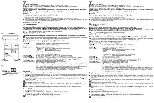
Elektrischer Anschluss (Bild �)<br />
Gefahrenhinweise<br />
Elektrischer Schlag bei Berühren spannungsführender Teile. Elektrischer Schlag kann zum Tod führen.<br />
Vor Arbeiten am Gerät Anschlussleitungen freischalten und spannungsführende Teile in der Umgebung abdecken.<br />
Die Verwendung anderer, als von <strong>ELKA</strong>-<strong>Elektronik</strong> zugelassener Systemstecker bzw. Verbindungsleitungen ist nicht<br />
gestattet und kann die elektrische Sicherheit sowie die Funktionalität des Systems negativ beeinflussen.<br />
<strong>e2i</strong>: Anschluss <strong>e2i</strong>-Systembus über mitgelieferten <strong>e2i</strong>-Systemstecker<br />
da+ / da-: Anschluss der DALI-Busleitung<br />
L / N: Anschluss der Netzspannung<br />
Die Steuerung von DALI-Teilnehmern über Fremdspannung (z. B. Netzspannung) am DALI-Anschluss ist nicht zulässig.<br />
Die DALI-Steuerspannung ist eine Funktionskleinspannung, FELV. Die Installation so ausführen, dass bei Freischalten eines<br />
Bereiches sowohl DALI- als auch Netzspannung führende Leitungen freigeschaltet sind.<br />
DALI-Teilnehmer können an verschiedene Außenleiter angeschlossen werden.<br />
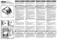
Bedien- und Anzeigeelemente der Handbedienung (Bild �)<br />
(1) Taste : Im Normalbetrieb: Aktivierung / Deaktivierung der Handbedienung.<br />
Im Handbetrieb: Auswahl der DALI-Gruppen<br />
(2) LED : Signalisiert bei LED EIN einen permanenten Handbetrieb.<br />
(3) LED State: Zustand während der Inbetriebnahme:<br />
Dauerlicht: Modul ist bereit zur Initialisierung (Selbsttest OK)<br />
Blinken: Modul wird initialisiert<br />
Aus: Keine Netzspannung vorhanden<br />
Zustand im Normalbetrieb:<br />
Dauerlicht: Anzeige Fehler, Modul ist nicht betriebsbereit<br />
Aus: Modul ist initialisiert und programmiert<br />
(4) Taste ON/▲ : Kurzes Drücken: Gruppe EIN / Langes Drücken: Gruppe heller dimmen.<br />
(5) Taste OFF/▼ : Kurzes Drücken: Gruppe AUS / Langes Drücken: Gruppe dunkler dimmen.<br />
(6) LED Group State: Signalisiert bei LED EIN im Handbetrieb eine eingeschaltete Gruppe (Helligkeit: 1...100 %).<br />
Signalisiert bei LED AUS im Handbetrieb eine ausgeschaltete Gruppe (Helligkeit: 0 %).<br />
(7) Taste ALL OFF: Alle Gruppen AUS (nur im permanenten Handbetrieb).<br />
(8) 7-Segmentanzeige:<br />
Betriebsarten<br />
Zeigt die in der Handbedienung angewählte DALI-Gruppe an<br />
(01...16 / blinkend = Gruppe gesperrt).<br />
Handbedienung im unprogrammierten Zustand, noch keine Gruppenzuordnungen (Broadcast-<br />
Betrieb). Alle im System vorhandenen DALI-Betriebsgeräte werden gemeinschaftlich angesteuert.<br />
Automatischer Gerätetausch. Die Anzeigedauer ist abhängig von der Anzahl der angeschlossenen<br />
DALI-Betriebsgeräte. Anzeige erlischt, wenn der Gerätetausch ohne Fehler beendetwird.<br />
Fehler, der während des automatischen Gerätetausches aufgetreten ist. Der Gerätetausch<br />
konnte nicht durchgeführt werden. Die Anzeige erlischt nach 3 s automatisch.<br />
• Busbetrieb: Bedienung über diverse Busgeräte (z. B. Tastsensoren)<br />
• Kurzzeitiger Handbetrieb: Manuelle Bedienung vor Ort mit Tastenfeld, automatische Rückkehr in Busbetrieb. Zum Aktivieren<br />
Taste kurz, < 1 s, betätigen. Nach Durchlauf aller DALI-Gruppen oder 5 s ohne Tastenbetätigung kehrt das Gerät selbsttätig<br />
•<br />
in den Busbetrieb zurück.<br />
Permanenter Handbetrieb: Ausschließlich manuelle Bedienung am Gerät. Zum Aktivieren oder Deaktivieren Taste<br />
destens 5 s betätigen.<br />
Im Handbetrieb ist kein Busbetrieb möglich.<br />
Bei Busausfall ist Handbetrieb möglich.<br />
min-<br />
Eine Handbedienung erfolgt ausschließlich über die Tasten am DALI-Modul. Das <strong>e2i</strong>-Handbedienmodul Typ EHB 5, Art.-Nr.<br />
140 01 010 wird nicht unterstützt.<br />
Nach Busausfall und -wiederkehr sowie nach Netzausfall und -wiederkehr schaltet das Gerät in den Busbetrieb.<br />
Einzelne DALI-Gruppen sperren / entsperren<br />
• Permanenten Handbetrieb aktivieren.<br />
• Taste so oft kurz, < 1 s, betätigen, bis die Anzeige die gewünschte Gruppe anzeigt.<br />
• Tasten ON/▲ und OFF/▼ gleichzeitig mindestens 5 s betätigen<br />
Im gesperrten Zustand blinkt die Nummer der gewählten DALI-Gruppe.<br />
Eine gesperrte DALI-Gruppe kann im Handbetrieb bedient werden.<br />
Safety instructions<br />
Electrical equipment must be installed and fitted by qualified electricians only.<br />
Failure to observe the instructions may cause damage to the device and result in fire or other hazards.<br />
The device is not suited for safe disconnection of the mains supply.<br />
The DALI control voltage is a functional extra-low voltage (FELV). Safe separation between <strong>e2i</strong> and DALI in installations<br />
must be ensured.<br />
These operating instructions are part of the product and must be left with the final customer.<br />
Mounting<br />
Fit the device by snap-fastening on a mounting rail 35 x 7.5 mm acc. to DIN EN 50022<br />
The following basic instructions must be oberved during the installation:<br />
• �The modules must be mounted in the order stipulated by tool in project planning.<br />
•� Modules must not be added or removed without adapting the project planning and download into the <strong>e2i</strong>-controller, because<br />
this might lead to malfunctions of the system.<br />
Electrical connection (fig. �)<br />
DANGER!<br />
Electric shock in case of accidental contact with live parts. Electric shocks may be fatal.<br />
Before working on the device, cut out the mains supply and cover up live parts in the surroundings.<br />
The use of system plugs or connection cables other than those recommended by <strong>ELKA</strong>-<strong>Elektronik</strong> is not admissible and<br />
can have a negative effect on the electric safety and the functionality of the system.<br />
<strong>e2i</strong>: Connection <strong>e2i</strong> system bus via the included <strong>e2i</strong> system plug<br />
da+ / da-: Connection of the DALI bus lead<br />
L / N: Connection of mains voltage<br />
The control of DALI devices via external voltage (e.g. mains voltage) at the DALI connection is not admissible.<br />
The DALI control voltage is a functional extra-low voltage FELV. Plan the installation in such a way that all lines carrying DALI<br />
voltage as well as mains voltage are disconnected when the supply to a sector is disconnected.<br />
DALI devices can be connected to different phase conductors.<br />
Operating and display elements of manual control (fig. �)<br />
(1) Key : In normal mode: activating/deactivating of manual control mode.<br />
In manual control mode: selection of the DALI groups<br />
(2) LED : ON: permanent manual control mode active.<br />
(3) LED State: State during commissioning:<br />
Permanent light: module is ready for initialization (self-test OK)<br />
Blinking: module is being initialized<br />
OFF: no mains voltage<br />
State in normal mode:<br />
Permanent light: display shows Error, module is not operational<br />
OFF: Module is initialized and programmed<br />
(4) Key ON/▲ : Switching on or increasing brightness.<br />
(5) Key OFF/▼ : Switching off or reducing brightness.<br />
(6) LED Group State: LED ON in manual control mode: group is switched on (brightness: 1...100 %).<br />
LED OFF in manual control mode: group is switched off (brightness: 0 %).<br />
(7) Key ALL OFF: All groups OFF (only in permanent manual control).<br />
(8) 7-segmant display:<br />
Operating modes<br />
Indicates the DALI group selected in manual control<br />
(01...16 / blinking = group blocked).<br />
Manual control mode not programmed, no group assignments yet (broadcast mode). All DALI<br />
operating devices in the system are controlled in common.<br />
Automatic device exchange. The display duration depends on the number of connected DALI operating<br />
devices. The display goes out when the device exchange has been terminated without fault.<br />
An error has incurred during the automatic device exchange. A device exchange was not possible.<br />
The display goes out automatically after 3 s.<br />
• Bus mode: operation via various bus devices (e.g. push-button sensors)<br />
• Temporary manual control mode: manual operation locally with keypad, automatic return to bus mode. To activate, press<br />
key briefly, < 1 s. After sequence of all DALI groups or 5 s without operation of a key, the device switches back to bus mode<br />
automatically.<br />
• Permanent manual control mode: only manual control locally on device. To activate or deactivate press key for at least 5 s.<br />
Bus operation in manual control mode disabled.<br />
Manual control in the event of bus failure enabled.<br />
Manual control only via the keys at the DALI module. The <strong>e2i</strong> manual control module type EHB 5, Art. No. 140 01 010 is not<br />
supported.<br />
After failure and return of bus voltage and after failure and return of mains voltage, the device switches over to the bus<br />
mode.<br />
Disabling individual DALI groups<br />
• The device is in the permanent manual control mode.<br />
• Press the key several times briefly < 1 s until the desired group is displayed.<br />
• Press the ON/▲�and OFF/▼ keys together for at least 5 s. The number of the selected DALI group flashes.<br />
The DALI group is disabled.<br />
A disabled DALI group can be operated in the manual control.