½Caution - Merten
½Caution - Merten
½Caution - Merten

Erfolgreiche ePaper selbst erstellen
Machen Sie aus Ihren PDF Publikationen ein blätterbares Flipbook mit unserer einzigartigen Google optimierten e-Paper Software.
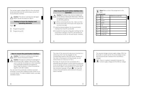
The contact supply voltage (SELV) for the connected<br />
buttons/switches and the control lamps comes from<br />
the push-button interface.<br />
Caution: The device could become damaged.<br />
½ Never connect the device to 230 V!<br />
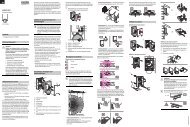
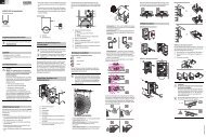
Figure !:<br />
Getting to know the displays and<br />
operating elements<br />
A Programming button<br />
B Programming LED<br />
¼<br />
¼<br />
16<br />
How to mount the push-button interface<br />
13<br />
Caution: The device could become damaged.<br />
Never connect the device to 230 V!<br />
Caution: The device could become damaged. If<br />
there are any 230 V cables in the vicinity, make<br />
sure to maintain the distances to them specified<br />
in the applicable standards and regulations.<br />
Never install the device in a flush-mounted box<br />
together with 230 V cables.<br />
You can insert the push-button interface into flushmounted<br />
or cavity-wall installation boxes (D 60 mm) or<br />
in junction boxes. To make installation easier, use deep<br />
installation boxes.<br />
Caution:The device may only be installed and<br />
½ connected by professional electricians. Observe<br />
the regulations valid in the country of use, as well<br />
as valid EIB guidelines.<br />
| When connecting the bus line, make sure that<br />
How to put the push-button interface into<br />
operation<br />
the line terminals of the inputs and outputs are<br />
not short-circuited.<br />
1 Load the physical address into the push-button<br />
interface from the ETS via the EIB.<br />
2 Complete the required configuration settings for the<br />
push-button interface in the ETS, and transfer the<br />
configuration by EIB into the push-button interface.<br />
14<br />
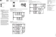
The cores of the inputs and outputs are mounted on a<br />
cable plug which must be plugged into the<br />
corresponding socket at the push-button interface. If<br />
the cores in the plug are not long enough, you can<br />
extend these to a maximum of 7.5 m.<br />
Normally, the inputs are to be connected with a<br />
potential-free push-button or switch and the outputs are<br />
to be connected with the corresponding control lamps<br />
(low-current LEDs) in this push-button or switch (see<br />
the connection example in Figure „). You may only<br />
connect the push-buttons and switches to the pushbutton<br />
interface.<br />
17<br />
| Note:Make a note of the assignment in the<br />
table.<br />
Pin assignment<br />
GD grey Reference potential<br />
E1 blue<br />
E2 brown<br />
E3 green<br />
E4 red<br />
A1 white-blue<br />
A2 white-brown<br />
A3 white-green<br />
A4 white-red<br />
The required voltage (contact supply voltage, SELV) for<br />
the button or switch and for the control lamps comes<br />
from the push-button interface (from the EIB bus<br />
voltage).<br />
| There is no galvanic separation between the<br />
contact supply voltage and the EIB bus voltage.<br />
18<br />
15