1 B 2 B 3 4 BB 1 A 2 A 3 4 AA - Merten
1 B 2 B 3 4 BB 1 A 2 A 3 4 AA - Merten
1 B 2 B 3 4 BB 1 A 2 A 3 4 AA - Merten

Sie wollen auch ein ePaper? Erhöhen Sie die Reichweite Ihrer Titel.
YUMPU macht aus Druck-PDFs automatisch weboptimierte ePaper, die Google liebt.
Anleitung_764193.book Seite 28 Dienstag, 15. Oktober 2002 11:44 11<br />
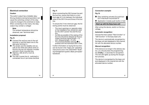
Electrical connection<br />
Caution<br />
The switch output has a bistable relay.<br />
Strong vibrations during transportation can<br />
cause the switching contact of the relay<br />
output to change to the switched-on state.<br />
When connecting to the mains, the relay<br />
output may contain a voltage!<br />
Note<br />
The ambient temperature should be<br />
observed, see "technical data".<br />
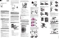
Installation proposal:<br />
Fig. E:<br />
➊ Connect the red bus wire to the red<br />
terminal (+) and the black one to the<br />
dark grey terminal (-).<br />
➋ The screen and the stability wire as<br />
well as the white and yellow wires of<br />
the bus line are not required. Insulate<br />
and put in flush-mounted box.<br />
➌ Wall box, DIN 49 073, Form B,<br />
ø60mm<br />
➍ The 230 V power line (L, switched) is<br />
connected via a 2-pin screw terminal.<br />
28<br />
Fig. F:<br />
When connecting the 230 V power line and<br />
the bus line, ensure that there is a minimum<br />
gap of 4 mm between the individual<br />
wires of the 230 V line and those of the bus<br />
line.<br />
To ensure the 4 mm minimum gap, the following<br />
points must be observed:<br />
- The input openings on opposite sides<br />
of the installation box should be used<br />
for the 230 V power line and the bus<br />
line.<br />
- As little as possible of the casing of the<br />
bus line should be stripped at the bus<br />
supply terminal (casing length = 12<br />
mm, stripped length = 6 mm).<br />
- The enclosed flexible sleeving ➊ is<br />
pushed over the individual 230 V lines.<br />
Further information on laying the bus line<br />
can be found in the "base unit" operating<br />
instructions and in the ZVEI/ZVEH "Building<br />
management system, Basic principles"<br />
handbook.<br />
29<br />
Anleitung_764193.book Seite 29 Dienstag, 15. Oktober 2002 11:44 11<br />
Anleitung_764193.book Seite 30 Dienstag, 15. Oktober 2002 11:44 11<br />
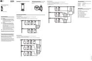
Connection example:<br />
Fig. G:<br />
➊ Easy switching actuator for push-button<br />
4-fold flush-mount/230/10<br />
➋ Application module push-button 4-fold<br />
Start-up with the Easy base unit<br />
After wiring the device, switch on the bus<br />
voltage.<br />
Automatic recognition:<br />
Choose the menu option "New function" or<br />
"Edit function" in the Easy base unit.<br />
The device is automatically recognised by<br />
the base unit and displayed in the channel<br />
list with the allocated device number.<br />
Manual recognition:<br />
If the device is no longer in the delivery status,<br />
you should press the programming<br />
key briefly (< 2 seconds) for recognition.<br />
The red LED lights up during the recognition<br />
process.<br />
The device is recognised by the base unit<br />
and displayed in the channel list with the<br />
allocated device number.<br />
30