IP69K - May KG
IP69K - May KG
IP69K - May KG

Sie wollen auch ein ePaper? Erhöhen Sie die Reichweite Ihrer Titel.
YUMPU macht aus Druck-PDFs automatisch weboptimierte ePaper, die Google liebt.
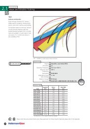
K A B E LV E R S C H R A U B U N G E N<br />
C A B L E G L A N D S<br />
K O M P E T E N Z I M K A B E L M A N A G E M E N T<br />
C O M P E T E N C E I N C A B L E M A N A G E M E N T
Kabeleinführungen mit System<br />
Universell – individuell – praxisorientiert<br />
Cable entries with system<br />
Universal – individual – practice-oriented<br />
Einleitung/Introduction · 1
Vertretungen<br />
Representatives<br />
99<br />
2 · Einleitung/Introduction<br />
10<br />
18<br />
03<br />
44<br />
04<br />
05<br />
42<br />
Jens Thomsen<br />
Jörg Schmidt Marc Lilkendey<br />
Norbert Gliedstein Manfred Rupprecht Christian Pistel Peter Hein<br />
Alfred Vittinghoff Andreas Michalschyk<br />
Thomas Hillebrand Patrick Vittinghoff<br />
Jörg Bobert<br />
Klaus Zimmermann<br />
Jörg Fritzel<br />
Thomas Brüll<br />
Martin Geng<br />
Günther Obilcnik Alexander Wagner André Schmid Harald Wölfle<br />
44<br />
D-06493 Neudorf/Harz<br />
Ing.-Büro Automatisierungstechnik<br />
Dr.-Ing. Klaus Zimmermann<br />
Hauptstraße 15<br />
Tel.: +49 39484 6364<br />
Fax: +49 39484 6319<br />
E-Mail: ib-zimmermann@gmx.de<br />
18<br />
D-28816 Stuhr-Moordeich<br />
Thomsen GmbH + Co. <strong>KG</strong><br />
Industrie-Vertretungen<br />
Moordeicher Landstraße 27<br />
Tel.: +49 421 56522-0<br />
Fax: +49 421 56522-55<br />
E-Mail: pflitsch@thomsen-stuhr.de<br />
www.thomsen-stuhr.de<br />
04<br />
D-90530 Wendelstein<br />
Kilian & Gans GmbH & Co. <strong>KG</strong><br />
In der Gibitzen 27<br />
Tel.: +49 9129 90656-60<br />
Fax: +49 9129 90656-99<br />
E-Mail: info@kilian-gans.de<br />
www.kilian-gans.de<br />
99<br />
D-40822 Mettmann<br />
Wagner GmbH<br />
Werksvertretungen<br />
der Elektroindustrie<br />
Auf dem Hüls 6<br />
Tel.: +49 2104 955-0<br />
Fax: +49 2104 754-26<br />
E-Mail: info@wagnergmbh.de<br />
www.wagnergmbh.de<br />
10<br />
D-60322 Frankfurt<br />
Ingenieur-Büro Stapf GmbH<br />
Fellnerstraße 11<br />
Tel.: +49 69 153004-0<br />
Fax: +49 69 59622-87<br />
E-Mail: stapf@stapf.de<br />
www.stapf.de<br />
05<br />
D-10999 Berlin<br />
G. Hentschel<br />
Vertriebs GmbH<br />
Paul-Lincke-Ufer 39/40<br />
Tel.: +49 30 617895-0<br />
Fax: +49 30 617895-11<br />
E-Mail: info@hentschel-vertrieb.de<br />
www.hentschel-vertrieb.de<br />
42<br />
D-07554 Gera<br />
IBS SCHMID SystemPartner GmbH<br />
Am Weinberg 31<br />
Tel.: +49 36695 31259<br />
Fax: +49 36695 31749<br />
E-Mail: info@ibs-gruppe.de<br />
www.ibs-gruppe.de<br />
03<br />
D-76344 Eggenstein-Leo.<br />
IBS SCHMID SystemPartner GmbH<br />
Hauptstraße 135<br />
Tel.: +49 721 97057-0<br />
Fax: +49 721 97057-57<br />
E-Mail: info@ibs-gruppe.de<br />
www.ibs-gruppe.de
Australia, New Zealand<br />
Siemens Ltd Automation & Drives<br />
Tel.: +61 3 972121-55<br />
Fax: +61 3 972179-70<br />
E-Mail: iac.sales.au@siemens.com<br />
www.siemens.com.au<br />
Brazil<br />
HARTING Ltda.<br />
Tel.: +55 11 5035 0073<br />
Fax: +55 11 5034 4743<br />
E-Mail: br@HARTING.com<br />
www.HARTING.com<br />
Denmark<br />
COFERRO A/S<br />
Tel.: +45 44 845555<br />
Fax: +45 44 846706<br />
E-Mail: coferro@coferro.dk<br />
www.coferro.dk<br />
France<br />
EUCHNER France S.A.R.L.<br />
Tel.: +33 1 390990-90<br />
Fax: +33 1 390990-99<br />
E-Mail: info@euchner.fr<br />
www.euchner.fr<br />
India<br />
ALLTRONIX<br />
Tel.: +91 80 40838383<br />
Fax: +91 80 40838305<br />
E-Mail: mail@alltronixin.com<br />
www.alltronixindia.com<br />
Kazakhstan<br />
Ex-Con-East<br />
Tel.: +7 7272 707389<br />
E-Mail: kazakhstan@ex-con-east.kz<br />
www.ex-con-east.kz<br />
Poland<br />
EX-CON Sp. z.o.o.<br />
Tel.: +48 71 7947047<br />
Fax: +48 71 7947037<br />
E-Mail: info@ex-con.pl<br />
www.ex-con.pl<br />
Russia<br />
000 AT electro Moskau<br />
Tel.: +7 495 9214425<br />
Fax: +7 495 9264645<br />
E-Mail: info@at-e.ru<br />
www.at-e.ru<br />
Sweden<br />
AB Novum<br />
Tel.: +46 42 151030<br />
Fax: +46 42 161666<br />
E-Mail: mail@abnovum.se<br />
www.abnovum.se<br />
Austria<br />
Euchner Ges.m.b.H.<br />
Tel.: +43 2252 42191<br />
Fax: +43 2252 45225<br />
E-Mail: info@euchner.at<br />
www.euchner.at<br />
Bulgaria<br />
Comet Electronics<br />
Tel.: +359 2 9155800<br />
Fax: +359 2 9515267<br />
E-Mail: office@comet.bg<br />
www.comet.bg<br />
Spain, Portugal<br />
INTERTRONIC INTERNACIONAL, S. L.<br />
Tel.: +34 96 3758050<br />
Fax: +34 96 3751022<br />
E-Mail: info@intertronic.es<br />
www.intertronic.es<br />
Great Britain<br />
Walter Logan & Co. Ltd.<br />
Tel.: +44 208 4460161<br />
Fax: +44 208 4455137<br />
E-Mail: info@walterlogan.com<br />
www.walterlogan.com<br />
Italy<br />
TEAFLEX S.p.A<br />
Tel.: +39 039 2752860<br />
Fax: +39 039 471503<br />
E-Mail: teaflex@teaflex.com<br />
www.teaflex.com<br />
R.O.M.E. Electricity<br />
Representative Office<br />
Middle East<br />
R.O.M.E. Electricity<br />
Regional Office Middle East<br />
Tel.: +971 48 810591<br />
Fax: +971 48 810593<br />
E-Mail: pflitsch@rome-electricity.com<br />
www.rome-electricity.com<br />
Poland<br />
MERA Sp. z o. o.<br />
Tel.: +48 22 86376-50<br />
Fax: +48 22 86387-40<br />
E-Mail: mera@mera-sp.com.pl<br />
www.mera-sp.com.pl<br />
Serbia<br />
COMET ELECTRONICS d.o.o<br />
Tel.: +381 11 2134180<br />
Fax: +381 11 3113942<br />
E-Mail: office@comet.rs<br />
www.comet.rs<br />
Switzerland<br />
InduPart AG<br />
Tel.: +41 44 49690-30<br />
Fax: +41 44 49690-39<br />
E-Mail: mail@indupart.ch<br />
www.indupart.ch<br />
Belgium, Luxemburg<br />
Elmeco Services Belgium b.v.b.a. s.p.r.l.<br />
Tel.: +32 54 321419<br />
Fax: +32 54 325770<br />
E-Mail: info@elmeco.be<br />
www.elmeco.be<br />
Hong Kong, China<br />
HARTING Shanghai<br />
Tel.: +86 2163862200/Ext. 666<br />
Fax: +86 2163868636<br />
E-Mail: cn@harting.com<br />
www.harting.com.cn<br />
Finland<br />
Ex-Tekniikka Oy<br />
Tel.: +358 207920-790<br />
Fax: +358 207920-791<br />
E-Mail: info@extekniikka.fi<br />
www.extekniikka.fi<br />
Greece<br />
2 KAPPA Ltd<br />
Tel.: +30 23 107755-12<br />
Fax: +30 23 107755-14<br />
E-Mail: info@2kappa.gr<br />
www.2kappa.gr<br />
Japan<br />
Cychrome Co., Ltd.<br />
Tel.: +81 45 6 6437-11<br />
Fax: +81 45 6 6437-44<br />
www.cychrome.com<br />
Netherlands<br />
HEMMINK B.V.<br />
Tel.: +31 38 46982-00<br />
Fax alg.: +31 38 46982-10<br />
Fax verk.:+31 38 46982-99<br />
E-Mail: info@hemmink.nl<br />
www.hemmink.nl<br />
Poland<br />
Soyter Sp. z.o.o.<br />
Tel.: +48 22 75282-55<br />
Fax: +48 22 72205-50<br />
E-Mail: handlowy@soyter.pl<br />
www.soyter.pl<br />
Slovakia<br />
E-comps s.r.o.<br />
Tel.: +421 2 446348-15<br />
Fax: +421 2 446348-16<br />
E-Mail: info@e-comps.sk<br />
www.e-comps.sk<br />
Ukraine<br />
AT Electronics Kiev<br />
Tel.: +380 44 2192219<br />
Fax: +380 44 2192219<br />
E-Mail: info@at-e.com.ua<br />
www.at-e-com.ua<br />
electronic ®<br />
Czech Republic<br />
ZTC electronic<br />
Tel.: +420 2 67910082<br />
Fax: +420 2 67910641<br />
E-Mail: ztc@ztc.cz<br />
www.ztc.cz<br />
Finland<br />
Murrelektronik Oy<br />
Tel.: +358 3 88240-00<br />
Fax: +358 3 88240-40<br />
E-Mail: myynti@murri.fi<br />
www.murri.fi<br />
Hungary<br />
Euchner GmbH<br />
Tel.: +36 23 4283-74<br />
Fax: +36 23 4283-75<br />
E-Mail: info@euchner.hu<br />
www.euchner.hu<br />
Japan<br />
HARTING K.K.<br />
Tel.: +81 45 47634-56<br />
Fax: +81 45 47634-66<br />
E-Mail: jp@harting.com<br />
www.HARTING.co.jp<br />
Norway<br />
Rontech AS<br />
Tel.: +47 31 305656<br />
Fax-alg. +31 31 305852<br />
E-Mail: Ronny@rontech.no<br />
www.rontech.no<br />
Romania<br />
Comet Electronics Srl<br />
Tel.: +40 31 2262222<br />
Fax: +40 21 2434090<br />
E-Mail: office@comet.srl.ro<br />
www.comet.srl.ro<br />
MEC<br />
South Korea<br />
Mahani Electric Co., LTD.<br />
Tel.: +82 2 2194-3300<br />
Fax: +82 2 2194-3398<br />
E-Mail: admin@hanmec.co.kr<br />
www.hanmec.co.kr<br />
USA<br />
Conta-Clip, Inc.<br />
Tel.: +1 732 56407-05<br />
Fax: +1 732 56407-06<br />
E-Mail: info@contaclipinc.com<br />
www.contaclipinc.com<br />
Importeure<br />
Importers<br />
Einleitung/Introduction · 3
Anwendungsbeispiele<br />
Examples of application<br />
4 · Einleitung/Introduction<br />
3
Einleitung/Introduction · 5
Das PFLITSCH System<br />
Anforderungen& Problemlösungen<br />
The PFLITSCH System<br />
Requirements & problem solutions<br />
Anforderung<br />
Requirement<br />
Hohe mechanische Beanspruchung<br />
High mechanical stress<br />
Qualitäts-Verschraubung aus Kunststoff<br />
Quality gland made of plastic<br />
Kunststoffverschraubung mit hoher Chemikalienbeständigkeit<br />
Plastic gland with high chemical resistance<br />
Verschraubungen in der Lebensmittelindustrie und für Außeninstallationen<br />
Glands in the food industry and for installation outside<br />
Große Dichtbereiche<br />
Large sealing ranges<br />
Große Kabelquerschnitte<br />
Large cable diameter<br />
Kabelverschraubungen M6 – M10<br />
Cable glands M6 – M10<br />
Kleiner Durchbruch, großer Kabeldurchmesser<br />
Small opening, large cable diameter<br />
Große Wandstärken<br />
Large wall thicknesses<br />
Zoll-Gewinde (Whitworth)<br />
Inch thread (Whitworth)<br />
NPT-Gewinde (kegelig)<br />
NPT-thread<br />
Zertifikate/Normen<br />
Certificates/Norm<br />
Kabel mit Geflechtschirm<br />
Cable with braided screen<br />
EMV Schutzschlauch<br />
EMC protective hose<br />
Kabel mit Stahldrahtarmierung<br />
Cable with steel wire/tape armour<br />
6 · Einleitung/Introduction<br />
Lösung/Produkt<br />
Solution / Product<br />
Standardverschraubungen<br />
Extensions<br />
UNI Dicht Ms, m + Pg, blueglobe Ms<br />
UNI Dicht brass, m + Pg, blueglobe Ms<br />
UNI Dicht VA, m + Pg, blueglobe VA<br />
UNI Dicht AISI 303, m + Pg, blueglobe AISI 303<br />
UNI Dicht PA, m + Pg, blueglobe PA<br />
UNI Dicht PA, m + Pg, blueglobe PA<br />
UNI Dicht PVDF, m + Pg<br />
UNI Dicht PVDF, m + Pg<br />
UNI Dicht VA, m + Pg, blueglobe CLEAN<br />
UNI Dicht AISI 303, m + Pg, blueglobe CLEAN<br />
UNI Dicht PVDF, m + Pg<br />
UNI Dicht PVDF, m + Pg<br />
blueglobe<br />
blueglobe<br />
UNI Dicht Maxi, m + Zoll<br />
UNI Dicht Maxi, m + inch<br />
UNI Dicht Mini Ms, m<br />
UNI Dicht Mini brass, m<br />
Erweiterungen<br />
Solution / Product<br />
UNI Dicht erweitert Ms, PA, PVDF m+ Pg<br />
UNI Dicht extension brass, PA, PVDF, m + Pg<br />
Anschlussgewinde<br />
Connection thread<br />
15 mm UNI Dicht Ms, PVDF, VA, m + Pg, blueglobe<br />
15 mm UNI Dicht brass, PVDF, AISI 303, m + Pg<br />
50 mm UNI Dicht Schottverschraubung Ms, m<br />
50 mm UNI Dicht Bulkhead Gland brass, m<br />
UNI Zoll Dicht nach DIN ISO 266 T1<br />
UNI inch Dicht DIN ISO 266 T1<br />
UNI NPT<br />
UNI NPT<br />
Zertifikate<br />
Certificates<br />
Zertifizierungen entnehmen Sie bitte den jeweiligen<br />
Produktseiten. Nähere Informationen zu Zertifikaten<br />
finden Sie auch im „Technischen Anhang“➝<br />
Certifications take you please from the respective product pages.<br />
Closer information to certificates you will also find in the<br />
“technical appendix”.➝<br />
EMV<br />
EMC<br />
UNI Entstör Dicht<br />
UNI interference Dicht<br />
UNI EMV Dicht<br />
UNI EMC Dicht<br />
UNI IRIS EMV Dicht<br />
UNI IRIS EMC Dicht<br />
UNI HF Dicht<br />
UNI HF Dicht<br />
UNI SVD, blueglobe TRI<br />
UNI SVD, blueglobe TRI<br />
blueglobe AC<br />
blueglobe AC<br />
Kapitel<br />
Chapter<br />
4 + 5<br />
4 + 5<br />
4 + 5<br />
4 + 5<br />
4 + 5<br />
4 + 5<br />
5<br />
5<br />
4 + 5<br />
4 + 5<br />
5<br />
5<br />
4<br />
4<br />
5<br />
5<br />
5<br />
5<br />
5<br />
5<br />
4 + 5<br />
4 + 5<br />
5<br />
5<br />
5<br />
5<br />
5<br />
5<br />
12<br />
12<br />
6<br />
6<br />
6<br />
6<br />
6<br />
6<br />
6<br />
6<br />
6<br />
6<br />
6<br />
6
Anforderung<br />
Requirement<br />
Erhöhte Zugbelastung am Kabel<br />
Increased tension load<br />
Biegebelastung am Kabel<br />
Bending load on the cable<br />
Zug- und Biegebelastung am Kabel<br />
Tensile and bending load on the cable<br />
Ein Durchbruch, mehrere Kabel<br />
One opening, several cables<br />
Verschlossene Kabelverschraubung<br />
Closed cable gland<br />
Flachkabel<br />
Flat cable<br />
Bus Kabel<br />
Bus cable<br />
Vorkonfektionierte Kabel<br />
Pre-assembled cable<br />
Glatte Kunststoffschläuche<br />
Smooth plastic hoses<br />
UL-Schlauch mit metallischem Stützwendel<br />
UL hose with metallic support spiral<br />
Wellrohr<br />
Corrugated conduit<br />
Hochflexible Schutzschlauchinstallation<br />
Flexible protection hoses<br />
Schutzschlauchinstallation für Metallschläuche<br />
Protection hoses for metal hose<br />
90° Kabelverschraubung<br />
90º cable gland<br />
Anflanschbare Kabelverschraubung<br />
Cable gland to be flanged on<br />
Nützliche Kleinteile<br />
Useful small parts<br />
Installieren & Montieren<br />
Installation & mounting<br />
Konstruktions- und Anwendungsinformationen<br />
Constructions- and application informations<br />
Bauformen/Normen/Prüfungen<br />
Shapes/standards/tests<br />
Lösung/Produkt<br />
Solution / Product<br />
Zug- und Biegeschutz<br />
Tension and bending protection<br />
UNI Zug Dicht, m + Pg<br />
UNI Strain relief Dicht, m + Pg<br />
UNI Klemm Dicht, m + Pg<br />
UNI Clamp Dicht, m + Pg<br />
blueglobe<br />
blueglobe<br />
Kabelstrumpf (Details auf Anfrage)<br />
Cable wire mesh (Details on request)<br />
UNI Biegeschutz Dicht, m + Pg<br />
UNI Bending Dicht, m + Pg<br />
UNI Flex Dicht, m + Pg<br />
UNI Flex Dicht, m + Pg<br />
UNI Biege Zug<br />
UNI Bending strain relief<br />
Sonder- und Mehrfach<br />
Special and multiple<br />
UNI Dicht Mehrfach, m + Pg<br />
UNI Dicht Multiple, m + Pg<br />
UNI Dicht Einsatz geschlossen, m + Pg, blueglobe, m<br />
UNI Dicht insert closed, m + Pg, blueglobe, m<br />
Verschlussbolzen<br />
Screw plug<br />
UNI Dicht Flach, m + Pg<br />
UNI Dicht Flat, m + Pg<br />
UNI Dicht ASI Bus, m + Pg<br />
UNI Dicht ASi Bus, m + Pg<br />
UNI Stecker, m + Pg<br />
UNI Connector, m + Pg<br />
Schlauch/Wellrohr<br />
Hose/Corrugated conduit<br />
UNI Schlauch Kabelverschraubung, m + Pg<br />
UNI Hose cable glands, m + Pg<br />
Schlauchstutzen, m + Pg<br />
Hose connection pieces, m + Pg<br />
UNI UL Schlauch Kabelverschraubung, m + Pg<br />
UNI UL Hose cable gland, m + Pg<br />
UNI Wellrohrverschraubungen, Wellrohre, m + Pg<br />
UNI corrugated conduit glands, m + Pg<br />
Roboter Schlauchverschraubung, m + Pg<br />
Robotic hose gland, m + Pg<br />
UNI SVD Schlauch-Kabelverschraubung, m + Pg<br />
UNI SVD hose cable gland, m + Pg<br />
Winkel/Flansche<br />
Angles/Flanges<br />
UNI Winkel, m + Pg<br />
UNI Angles, m + Pg<br />
UNI Flanschwinkel, m + Pg<br />
UNI Flange Angles, m + Pg<br />
Sonstiges<br />
Miscellaneous<br />
Zubehör<br />
Accessories<br />
Werkzeuge<br />
Tools<br />
Technischer Anhang<br />
Technical Appendix<br />
Kapitel<br />
Chapter<br />
5<br />
5<br />
5<br />
5<br />
4<br />
4<br />
-<br />
-<br />
5<br />
5<br />
5<br />
5<br />
5<br />
5<br />
5<br />
5<br />
4 + 5<br />
4 + 5<br />
7 + 10<br />
7 + 10<br />
5<br />
5<br />
5<br />
5<br />
5<br />
5<br />
9<br />
9<br />
9<br />
9<br />
9<br />
9<br />
9<br />
9<br />
9<br />
9<br />
9<br />
9<br />
8<br />
8<br />
8<br />
8<br />
10<br />
10<br />
11<br />
11<br />
12<br />
12<br />
Einleitung/Introduction · 7
8 · Einleitung/Introduction
1<br />
2<br />
3<br />
4<br />
5<br />
6<br />
7<br />
8<br />
9<br />
10<br />
11<br />
12<br />
Unternehmen Company<br />
Neuheiten Novelties<br />
Service & Lösungen Service & Solutions<br />
blueglobe blueglobe<br />
UNI Dicht UNI Dicht<br />
EMV EMC<br />
ATEX ATEX<br />
Winkel Angle<br />
Schläuche & -Verschraubungen Hoses & -glands<br />
Zubehör Accessories<br />
Werkzeuge Tools<br />
Technischer Anhang Technical appendix
Stichwortverzeichnis<br />
10 · Einleitung/Introduction
Einleitung/Introduction · 11<br />
Stichwortverzeichnis<br />
Produktbezeichnung/Ausführung Produktbezeichnung Ausführung Material Gewinde Seite Produktbezeichnung/Ausführung Material Gewinde Seite<br />
Kapitel 4 – blueglobe<br />
Kabelverschraubung blueglobe Ms M 49<br />
Polyamid M 48<br />
VA 1.4305 M 50<br />
Kapitel 5 – UNI Dicht<br />
VA 1.4571 M 51<br />
i Übersicht UNI Dicht Artikel-Nummer M/Pg 58-59<br />
Komponenten M 108-109<br />
Pg 158-161<br />
Systemteile M 56-57<br />
Pg 112-113<br />
Einsatz Maxi/Flach TPE/TPE-V M 64<br />
Maxi/Mehrfach TPE M 64<br />
Geschlossen Ms M 86<br />
Pg 134<br />
PA 6-3 M 86<br />
Pg 134<br />
PVDF M 86<br />
Pg 134<br />
VA 1.4305 M 86<br />
Pg 134<br />
Einzelkomponenten Mehrfach Ms M 85<br />
Pg 133<br />
PA 6-3 M 85<br />
Pg 133<br />
PVDF M 85<br />
Pg 133<br />
VA 1.4305 M 85<br />
Pg 133<br />
Gegenmutter Maxi Ms M/Zoll 63<br />
Schaft Ms M 66<br />
Kabelverschraubung ASi-Bus Ms M 90<br />
Pg 138<br />
PA 6-3 M 91<br />
Pg 139<br />
PVDF M 91<br />
Pg 139<br />
VA 1.4305 M 90<br />
Pg 138<br />
Biege Zug Ms M 105<br />
Pg 153<br />
PA 6-3 M 106<br />
Pg 154<br />
PVDF M 107<br />
Pg 155<br />
Biegeschutz Ms M 99<br />
Pg 147<br />
PA 6-3 M 100<br />
Pg 148<br />
PVDF M 101<br />
Pg 149<br />
Edelstahl VA 1.4305 M 67<br />
Pg 115<br />
VA 1.4571 M 68<br />
Pg 116<br />
Kabelverschraubung Erweitert Ms M 74<br />
Pg 122<br />
PA 6-3 M 75<br />
Pg 123<br />
PVDF M 76<br />
Pg 124<br />
Flach Ms M 92-93<br />
Pg 140-141<br />
PA 6-3 M 92-93<br />
Pg 140-141<br />
PVDF M 92-93<br />
Pg 140-141<br />
VA 1.4305 M 92-93<br />
Pg 140-141<br />
Flex Ms M 102<br />
Pg 150<br />
Klemm Ms M 103-104<br />
Pg 151-152<br />
Kunststoff PA 6-3 M 69<br />
Pg 117<br />
PVDF M 70<br />
Pg 118<br />
Maxi Ms M 63<br />
Mehrfach Ms M 80-86<br />
Pg 128-133<br />
PA 6-3 M 80-85<br />
Pg 128-133<br />
PVDF M 80-85<br />
Pg 128-133<br />
VA 1.4305 M 80-85<br />
Pg 128-133<br />
Messing Ms M 62<br />
Pg 114<br />
Mini Ms M 65<br />
NPT Ms NPT 157<br />
Schott Ms M 66<br />
Stecker Ms M 87-88<br />
Pg 135-136<br />
PA 6-3 M 87-88<br />
Pg 135-136<br />
PVDF M 87-88<br />
Pg 135-136<br />
VA 1.4305 M 87-88<br />
Pg 135-136<br />
Zoll Ms Zoll 156<br />
Zug Ms M 96<br />
Pg 144<br />
PA 6-3 M 97<br />
Pg 145<br />
PVDF M 98<br />
Pg 146<br />
Verschlussbolzen PVDF 88+134<br />
Kapitel 6 – EMV<br />
Kabelverschraubung blueglobe AC Ms M 201<br />
blueglobe EMV Ms M 200<br />
blueglobe TRI Ms M 199<br />
Fortsetzung auf der nachfolgenden Seite<br />
Einleitung/Introduction · 11
Stichwortverzeichnis<br />
Produktbezeichnung/Ausführung Material Gewinde Seite Produktbezeichnung/Ausführung Material Gewinde Seite<br />
Kapitel 6 – EMV<br />
Kabelverschraubung EMV (Marine) Ms M 184<br />
EMV Ms M 182<br />
Pg 185<br />
Entstör Ms M 188-189<br />
Pg 190-191<br />
HF Ms M 174-176<br />
Pg 177-179<br />
HF-UL Ms M 198<br />
Pg 198<br />
Iris (Marine) Ms M 170<br />
Iris Ms M 168<br />
Pg 169<br />
SVD Ms M 194<br />
Pg 194<br />
Schirmdämpfungsvergleich EMV 171<br />
i Technische Informationen EMV 202-208<br />
Kapitel 7 – ATEX<br />
i<br />
i<br />
i<br />
i<br />
Anforderungen an Ex-Kabel- & Leitungsführungen 214-217<br />
Erläuterungen zum Explosionsschutz 292-298<br />
Informationen zu blueglobe ATEX 268-269<br />
Normen & Kennzeichnungen 218-225<br />
Blindstopfen Ex-e Edelstahl VA 1.4305 M 275<br />
Pg 278<br />
Messing Ms M 274<br />
Pg 277<br />
Entlüftungsstutzen Ex-e Ms M 288-289<br />
Erweit. & Reduz. Ex-d Messing Ms M 290-291<br />
Erweiterung Ex-e Messing Ms M ➝ M 275<br />
M ➝ Pg 278<br />
Pg ➝ M 276<br />
Kabelverschraubung AC Ms M 280-283<br />
Ex-d 286-287<br />
Messing Ms M 284-285<br />
Kabelverschraubung Blind-Einsatz Ms/VA M/Pg 251-252<br />
Ex-e PVDF M 234<br />
blueglobe AC Ms M 272<br />
blueglobe Ms M 270<br />
blueglobe VA 1.4305 M 271<br />
EMV Ms M 260-261<br />
Flach Ms/VA M 250<br />
PVDF M 236<br />
Geschlossen Ms/VA M/Pg 253<br />
PVDF M 235<br />
HF Ms M 254-257<br />
Pg 258-259<br />
IRIS (Marine) Ms M 266-267<br />
IRIS Ms M 262-264<br />
Pg 265-266<br />
Kunststoff PVDF M 226-229<br />
Pg 237-240<br />
Mehrfach Ms/VA M 247-249<br />
PVDF M 230-233<br />
Messing Ms M 241-242<br />
Pg 243<br />
12 · Einleitung/Introduction<br />
Kabelverschraubung Schlauch Ms M/Pg 244<br />
Ex-e Edelstahl VA 1.4305 M 245-246<br />
Reduktion Ex-e Messing Ms M ➝ M 274<br />
M ➝ Pg 279<br />
Pg ➝ M 276<br />
Pg ➝ M 279<br />
Pg ➝ Pg 277<br />
Verschlussbolzen Kunststoff PVDF 232<br />
Kapitel 8 – Winkel<br />
Flanschwinkel PA 6-3 M 306<br />
Pg 312<br />
kurz Zink M 305<br />
Pg 311<br />
lang Zink Pg 312<br />
Kupplung Ms M/Pg 308<br />
Schlauch-Kabel-Verschraubungswinkel PA 6-3 Pg 311<br />
Verschraubungwinkel PA 6-3 M 304<br />
Pg 309-310<br />
Zink/Ms M 302<br />
Pg 307<br />
Winkel mit Kupplung Zink/Ms M 303<br />
Pg 308<br />
Winkel PA 6-3 Pg 310<br />
Zink M 306<br />
Pg 309<br />
Kapitel 9 – Schläuche & -Verschraubungen<br />
Kabelverschraubung Schlauch Ms M 324-325<br />
PA 6-3 M 326<br />
Schlauch- Kunststoff PA 6-3 Pg 338<br />
Kabelverschraubung Messing Ms Pg 336-337<br />
SVD Ms M 316<br />
Pg 328<br />
UL Ms Pg 334<br />
PVDF M 323<br />
Pg 335<br />
Schlauch Silber PVC 343<br />
Schlauch Spiral PVC/Buna 343<br />
Schlauchstutzen Kunststoff PA 6-3 M 327<br />
Pg 339<br />
Messing Ms M 327<br />
Pg 339<br />
Schlauch- Roboter Ms M 318<br />
verschraubung Pg 330<br />
SVD Ms M 317<br />
Pg 329<br />
UL Ms M 322<br />
Spiralschlauch Stahlgeflecht PVC/Buna 341<br />
Schutzschlauch Metall Stahl verzinkt 341-342<br />
Verschraubung Wellrohr Ms M 320<br />
Pg 332<br />
PVDF M 321<br />
Pg 333<br />
Wellrohr leicht PA 6-3 340<br />
mittel PA 6-3 340
Produktbezeichnung/Ausführung Material Gewinde Seite<br />
Kapitel 10 – Zubehör<br />
Blindscheibe Polyamid 366<br />
Blindstopfen 6kt Ms M 361<br />
Pg 362<br />
VA 1.4305 M 362<br />
Pg 362<br />
Rund GFK M 364<br />
Pg 364<br />
Ms M 361<br />
Dichtring DIN Neoprene Pg 380<br />
Flach Centellen M/Pg 369<br />
Glatt PE M/Pg 370<br />
Rund LSR M/Pg 368<br />
NBR M/Pg 367<br />
Druckausgleichseinsatz<br />
Einsteck Polyamid 6 374<br />
Gewinde Metall M 375-376<br />
Polyamid 6 M 375<br />
Druckring DIN VA 1.4305 Pg 379<br />
Druckschraube Verbindung Ms Pg 371<br />
Erdunsglasche 378<br />
Erweiterung 6kt GFK M ➝ M 353<br />
Pg ➝ M 354<br />
Pg ➝ Pg 354<br />
Ms M ➝ M 351<br />
M ➝ Pg 352<br />
Pg ➝ M 352<br />
Rund Ms Pg ➝ Pg 353<br />
Gegenmutter DIN Ms Zoll 347<br />
Edelstahl VA 1.4305 M 349<br />
Pg 350<br />
Maxi Ms M 346<br />
Messing Ms M 346<br />
Pg 347<br />
Polyamid GFK M 350<br />
Pg 351<br />
Potentialausgleich Ms M 348<br />
Marine 348<br />
Pg 349<br />
Schaft Ms M 346<br />
Klemmnippel Messing Ms M/Pg 371<br />
Kupplung M/Pg 372<br />
Membranschraube 2-Komponenten PE M 377<br />
Reduktion 6kt GFK M ➝ M 359<br />
Pg ➝ M 360<br />
Pg ➝ Pg 360<br />
Ms M ➝ M 355<br />
M ➝ Pg 356<br />
Pg ➝ M 356<br />
Pg ➝ Pg 357-358<br />
Schlauchschelle Stahl 372<br />
Verschlussbolzen PVDF 365-366<br />
Verschlussschrauben GFK Pg 365<br />
Würgenippel Geschlossen PE M 376<br />
Offen PE M 377<br />
Zwischenstutzen 6kt Ms Pg 379<br />
M 363<br />
Kapitel 11 – Werkzeuge<br />
Abmantelwerkzeug 394<br />
Blechbohrer-Satz M 390<br />
Blechbohrer M 390<br />
Drehmomentschlüssel 387<br />
Sicherungsring-Zange 395<br />
Gewindebohrer M 388<br />
Pg 392<br />
Kombi-Bohrer M 389<br />
Pg 393<br />
Lochfräser M 388<br />
Pg 392<br />
Montageschlüsselsatz 386<br />
Montageschlüssel variabel 385<br />
Pyramidenbohrer M 389<br />
Pg 393<br />
Ringratsche offen 386<br />
Schlauchschere 395<br />
Schlüsseleinsätze 386<br />
Spitzmesser 394<br />
Steckschlüssel Stahl verz. M 384<br />
Pg 391<br />
Wellrohrschere 395<br />
Kapitel 12 – Technischer Anhang<br />
Stichwortverzeichnis<br />
Produktbezeichnung/Ausführung Material Gewinde Seite<br />
Abkürzungen/Erläuterungen 430-431<br />
Anschlussmaße blueglobe M 402<br />
UNI Dicht M 399<br />
Pg 401<br />
Anwendung blueglobe 410<br />
Anzugsmomente blueglobe M 402<br />
UNI Dicht M 399<br />
Pg 401<br />
Baumaße UNI Dicht M 398<br />
Pg 400<br />
Brandschutz 420-421<br />
Gegenüberstellung metrisch und Pg 413<br />
GL-Prüfung 422<br />
Gost-Zulassung 422<br />
Impressum 440<br />
IP-Schutzarten 414<br />
IP-Schutzartprüfung blueglobe 403<br />
Lochung auf Wunsch 407<br />
Montageabstände M 404<br />
Pg 405<br />
Montageanleitung blueglobe AC 411<br />
blueglobe EMV 412<br />
UNI EMV 408<br />
UNI Entstör Dicht 408<br />
UNI HF Dicht 409<br />
UNI IRIS Dicht 409<br />
Notizen 433-439<br />
PFLITSCH Marken 428-429<br />
PFLITSCH Prüffeld 423<br />
Schlagprüfung blueglobe 403<br />
Werkstoffe 424-427<br />
Zertifizierungen UNI Dicht/blueglobe M/Pg 415-419<br />
Zugentlastung blueglobe 403<br />
Unternehmen/Company · 13
Glossary<br />
Product designation Type Material Thread Page<br />
Chapter 4 – blueglobe<br />
cable gland blueglobe AISI 303 M 50<br />
AISI 316Ti M 51<br />
brass M 49<br />
polyamide M 48<br />
Chapter 5 – UNI Dicht<br />
i<br />
Overview UNI Dicht Art.-No. M/Pg 58-59<br />
Components M 108-109<br />
Pg 158-161<br />
Partial overview M 56-57<br />
Pg 112-113<br />
Cable gland ASi-Bus AISI 303 M 90<br />
Pg 138<br />
brass M 90<br />
Pg 138<br />
PA 6-3 M 91<br />
Pg 139<br />
PVDF M 91<br />
Pg 139<br />
Bending strain reliefbrass M 105<br />
Pg 153<br />
PA 6-3 M 106<br />
Pg 154<br />
PVDF M 107<br />
Pg 155<br />
Bending brass M 99<br />
Pg 147<br />
PA 6-3 M 100<br />
Pg 148<br />
PVDF M 101<br />
Pg 149<br />
Brass brass M 62<br />
Pg 114<br />
Bulkhead brass M 66<br />
Clamping brass M 103-104<br />
Pg 151-152<br />
Connector AISI 303 M 87-88<br />
Pg 135-136<br />
brass M 87-88<br />
Pg 135-136<br />
PA 6-3 M 87-88<br />
Pg 135-136<br />
PVDF M 87-88<br />
Pg 135-136<br />
Extended brass M 74<br />
Pg 122<br />
PA 6-3 M 75<br />
Pg 123<br />
PVDF M 76<br />
Pg 124<br />
Flat AISI 303 M 92-93<br />
Pg 140-141<br />
brass M 92-93<br />
Pg 140-141<br />
PA 6-3 M 92-93<br />
Pg 140-141<br />
14 · Einleitung/Introduction<br />
Product designation Type Material Thread Page<br />
Cable gland PVDF M 92-93<br />
Pg 140-141<br />
Flex brass M 102<br />
Pg 150<br />
Inch brass Inch 156<br />
Maxi brass M 63<br />
Mini brass M 65<br />
Multiple AISI 303 M 80-85<br />
Pg 128-133<br />
brass M 86<br />
Pg 128-133<br />
PA 6-3 M 80-85<br />
Pg 128-133<br />
PVDF M 80-85<br />
Pg 128-133<br />
NPT brass NPT 157<br />
Plastic PA 6-3 M 69<br />
Pg 117<br />
PVDF M 70<br />
Pg 118<br />
Stainless steel AISI 303 M 67<br />
Pg 115<br />
AISI 316Ti M 68<br />
Pg 116<br />
Strain relief brass M 96<br />
Pg 144<br />
PA 6-3 M 97<br />
Pg 145<br />
PVDF M 98<br />
Pg 146<br />
Insert maxi Flat TPE/TPE-V M 64<br />
Multiple TPE M 64<br />
Insert Closed AISI 303 M 86<br />
Pg 134<br />
brass M 86<br />
Pg 134<br />
PA 6-3 M 86<br />
Pg 134<br />
PVDF M 86<br />
Pg 134<br />
Lock nut Maxi brass M + Inch 63<br />
Shaft brass M 66<br />
Sealing plugs PVDF 88+134<br />
single components Multiple AISI 303 M 85<br />
Pg 133<br />
brass M 85<br />
Pg 133<br />
PA 6-3 M 85<br />
Pg 133<br />
PVDF M 85<br />
Pg 133<br />
Chapter 6 – EMV<br />
cable gland blueglobe AC brass M 201<br />
blueglobe EMC brass M 200<br />
blueglobe TRI brass M 199
Glossary<br />
Product designation Type Material Thread Page Product designation Type Material Thread Page<br />
Chapter 6 – EMV<br />
cable gland EMC (Marine) brass M 184<br />
EMC brass M 182<br />
Pg 185<br />
Interf. suppression brass M 188-189<br />
Pg 190-191<br />
HF brass M 174-176<br />
Pg 177-179<br />
HF-UL brass M 198<br />
Pg 198<br />
Iris (Marine) brass M 170<br />
Iris brass M 168<br />
Pg 169<br />
SVD brass M 194<br />
Pg 194<br />
Screen attenuation comparison EMC 171<br />
i Technical informations EMC 202-208<br />
Chapter 7 – ATEX<br />
i<br />
i<br />
i<br />
i<br />
Requirements made on ex-protected cable & line installations 214-217<br />
Information of blueglobe ATEX 268-269<br />
Satadards & designations 218-225<br />
Terms used in explosion protection 292-298<br />
Adapt. & Reduc. Ex-d Brass brass M 290-291<br />
Adaptor Ex-e Brass brass M ➝ M 275<br />
M ➝ Pg 278<br />
Pg ➝ M 276<br />
Blind plugs Ex-e Brass brass M 274<br />
Pg 277<br />
Stainless steel AISI 303 M 275<br />
Pg 278<br />
Breather Drain Ex-e Brass brass M 288-289<br />
Cable gland Ex-d AC brass M 280-283<br />
286-287<br />
Brass brass M 284-285<br />
Cable gland Ex-e Blind-insert brass/AISI M/Pg 251-252<br />
PVDF M 234<br />
blueglobe AC brass M 272<br />
blueglobe AISI 303 M 271<br />
brass M 270<br />
Brass brass M 241-242<br />
Pg 243<br />
Closed brass/AISI M/Pg 253<br />
PVDF M 235<br />
EMC brass M 260-261<br />
Flat brass/AISI M 250<br />
PVDF M 236<br />
HF brass M 254-257<br />
Pg 258-259<br />
Hose brass M/Pg 244<br />
IRIS (Marine) brass M 266-267<br />
IRIS brass M 262-264<br />
Pg 265-266<br />
Multiple brass 15mm 247-249<br />
PVDF M 230-233<br />
Plastic PVDF M 226-229<br />
Pg 237-240<br />
Reduction Ex Brass brass M ➝ M 274<br />
M ➝ Pg 279<br />
Pg ➝ M 276<br />
Pg ➝ Pg 277<br />
Stainless steel AISI 303 M 245-246<br />
Sealing plugs Plastic PVDF 232<br />
Chapter 8 – Winkel<br />
Angle with oupling zinc/brass M 303<br />
Pg 308<br />
Angle PA 6-3 Pg 310<br />
zinc M 306<br />
Pg 309<br />
Coupling brass MPg 308<br />
Flange Angle PA 6-3 M 306<br />
Pg 312<br />
Long zinc Pg 312<br />
Short zinc M 305<br />
Pg 311<br />
Gland angle PA 6-3 M 304<br />
Pg 309-310<br />
zinc/brass M 302<br />
Pg 307<br />
Hose-Cable-Gland Angle PA 6-3 Pg 311<br />
Chapter 9 – Hoses & -glands<br />
Cable Gland Hose brass M 324-325<br />
PA 6-3 M 326<br />
Conduit Gland Corrugated brass M 320<br />
Pg 332<br />
PVDF M 321<br />
Pg 333<br />
Corrugated Conduit Light PA 6-3 340<br />
Middle PA 6-3 340<br />
Hose Cable Gland Brass brass Pg 336-337<br />
PA PA 6-3 Pg 338<br />
SVD brass M 316<br />
Pg 328<br />
UL brass M 322<br />
Pg 334<br />
PVDF M 323<br />
Pg 335<br />
Hose Gland SVD brass M 317<br />
Robotic brass M 318<br />
Pg 330<br />
SVD brass Pg 329<br />
Hose Socket Brass brass M 327<br />
Pg 339<br />
PA PA 6-3 M 327<br />
Pg 339<br />
Hose/Metal Conduit Steel galv. 341-342<br />
Tube/steel braiding Spiral PVC/Buna 341<br />
Tube Silver PVC 343<br />
Spiral PVC/Buna 343<br />
Continuation on the next page<br />
Einleitung/Introduction · 15
Glossary<br />
Product designation Type Material Thread Page Product designation Type Material Thread Page<br />
Chapter 10 – Accessories<br />
Adapter Hexagonal brass M 363<br />
brass Pg 379<br />
Blind Disk polyamide 366<br />
Blind Plug Circular brass M 361<br />
GFK M 364<br />
Pg 364<br />
Hexagonal AISI 303 M 362<br />
Pg 362<br />
brass M 361<br />
Pg 362<br />
Clamping Nipple Brass brass M/Pg 371<br />
Clamping Ring DIN AISI 303 Pg 379<br />
Coupling brass M/Pg 372<br />
Earth Tag brass 378<br />
Extension Circular brass Pg ➝ Pg 353<br />
Hexagonal brass M ➝ M 351<br />
M ➝ Pg 352<br />
Pg ➝ M 352<br />
GFK M ➝ M 353<br />
Pg ➝ M 354<br />
Pg ➝ Pg 354<br />
Lock Nut AISI AISI 303 M 349<br />
Pg 350<br />
DIN brass Inch 347<br />
Equipot. bonding brass M 348<br />
Marine 348<br />
Pg 349<br />
Maxi brass M 346<br />
Polyamide GFK M 350<br />
Pg 351<br />
Shaft brass M 346<br />
Standard brass M 346<br />
Pg 347<br />
Membrane Screw 2-component PE M 377<br />
Pressure Balance Elem. Pressure polyamide 6 374<br />
Thread metal M 375-376<br />
polyamide 6 M 375<br />
Pressure Screw Connection brass Pg 371<br />
Recuction Hexagonal brass M ➝ M 355<br />
M ➝ Pg 356<br />
Pg ➝ M 356<br />
Pg ➝ Pg 357-358<br />
GFK M ➝ M 359<br />
Pg ➝ M 360<br />
Pg ➝ Pg 360<br />
Sealing Plugs PVDF 365-366<br />
Sealing Ring Circular LSR M/Pg 368<br />
NBR M/Pg 367<br />
DIN Neoprene Pg 380<br />
Flat Centellen M/Pg 369<br />
Smooth PE M/Pg 370<br />
Stop Ends GFK Pg 365<br />
Tube Clip Galv. steel Galv. steel 372<br />
Twisting Sleeves Closed PE M 376<br />
With aperture PE M 377<br />
16 · Unternehmen/Company<br />
Chapter 11 – Tools<br />
Assembly Key Set for Cable Glands 386<br />
Bore-Type Cutter M 388<br />
Pg 392<br />
Combined Drill HSS M 389<br />
Pg 393<br />
Corrugated-Tube Shears 395<br />
Hose Shears 395<br />
Insulation Stripper 394<br />
Keys 386<br />
Mounting Spanner Variable 385<br />
Circlip Pliers 395<br />
Pointed Knife 394<br />
Pyramid Drill HSS M 389<br />
Pg 393<br />
Screw Tap HSS/E steel M 388<br />
Pg 392<br />
Sheet Drill Kit M 390<br />
Sheet Drill M 390<br />
Socket Wrench Steel/galv. M 384<br />
Pg 391<br />
Torque Key 387<br />
Turn Key open 386<br />
Chapter 12 – Technical Appendix<br />
i<br />
Abbreviations/Explanations 430-431<br />
Application blueglobe 410<br />
Cerfifications M/Pg 415-419<br />
Connecton dimension blueglobe M 402<br />
UNI Dicht M 399<br />
Pg 401<br />
Fire prevention 420-421<br />
GL-Certification 422<br />
Gost-Certification 422<br />
Impact testing blueglobe 403<br />
Imprint 440<br />
Installation blueglobe AC 411<br />
blueglobe EMC 412<br />
UNI EMC 408<br />
UNI HF Dicht 409<br />
UNI Interferenced suppression 408<br />
UNI IRIS Dicht 409<br />
IP Protection class test blueglobe 403<br />
IP-Protection 414<br />
Materials 424-427<br />
Mounting distance M 404<br />
Pg 405<br />
Notes 433-439<br />
Perforation optional 407<br />
PFLITSCH testing field 423<br />
PFLITSCH Trademarks 428-429<br />
Sealing Ranges UNI Dicht M/Pg 413<br />
Strain Relief blueglobe 403<br />
System dimension UNI Dicht M 398<br />
Pg 400
1The<br />
Company<br />
Innovative, with practice-oriented product solutions<br />
1 9 1 9 - 2 0 0 9<br />
Das Unternehmen<br />
Innovativ, mit praxisorientierten Produktlösungen<br />
Unternehmen/Company · 17
Die neue Kompetenz<br />
im Kabelmanagement<br />
The new competence<br />
in cable management<br />
18 · Unternehmen/Company
Seit 90 Jahren überzeugt PFLITSCH mit innovativen,<br />
praxisorientierten und sicheren Produktlösungen<br />
rund um die industrielle Kabel füh -<br />
rung. Dabei überzeugt unser Unternehmen die<br />
Anwender in verschiedenen Branchen immer<br />
wieder durch frische Denkansätze und dialogorientiertes<br />
Handeln.<br />
Made in Germany für den Weltmarkt<br />
PFLITSCH Kabelverschraubungen und Kabelkanäle<br />
stehen überall auf der Welt für „Qualität<br />
Made in Germany“ – deutlich gekennzeichnet<br />
durch das sechseckige Markenzeichen mit seinen<br />
charakteristischen 12 Riefen. Als Spezialist<br />
für industrielles Kabelmanagement schaffen wir<br />
Standards und bieten unserem wachsenden<br />
Kundenkreis in aller Welt zukunftsorientierte<br />
Systemlösungen.<br />
Systembauteile für mehr Individualität<br />
Über 12.000 Systembauteile mit hohem Nutzwert<br />
kombinieren wir mit einem Dienstleistungsangebot,<br />
das von der Planung bis zur<br />
einbaufertigen Baugruppe reicht. Damit lassen<br />
sich Arbeitsabläufe optimieren, die Betriebs -<br />
sicherheit erhöhen und Gesamtkosten reduzieren.<br />
Unter dem Strich sind PFLITSCH Produkte<br />
preiswert im wahrsten Sinne des Wortes. Denn<br />
statt auf Billiglösungen zu setzen, bieten wir<br />
Systemkomponenten, die ihren Preis wert sind.<br />
Und das über eine lange Betriebsdauer.<br />
Damit aus Ideen und Anforderungen des Marktes<br />
schnell ein perfektes Serienprodukt wird,<br />
arbeiten Konstruktion, Werkzeugbau, Prototypen-Fertigung,<br />
Testlabor und Produktion<br />
Hand in Hand – natürlich nach internationalen<br />
Qua litäts- und Kundennormen.<br />
PFLITSCH has been convincing with innovative,<br />
practice-oriented and reliable product solutions<br />
all about industrial cable routing for 90 years.<br />
Here our company is constantly persuading<br />
users in various branches with fresh approaches<br />
and dialogue-oriented action.<br />
Made in Germany for the world market<br />
PFLITSCH cable glands and cable trunking stand<br />
for "Quality Made in Germany" throughout the<br />
world – clearly identified by the hexagonal<br />
brand mark with its characteristic 12 grooves.<br />
As specialists for industrial cable management,<br />
we create standards and offer our growing circle<br />
of customers around the world future-oriented<br />
system solutions.<br />
System components for more individuality<br />
We combine over 12,000 system components<br />
of a high benefit value with a range of services<br />
varying from planning to ready-for-installation<br />
assemblies. This enables us to optimise operational<br />
procedures, increase operational reliability<br />
and safety as well as reduce overall costs.<br />
The bottom line shows unequivocally that<br />
PFLITSCH products are, in the truest sense of<br />
the word, value for money. This has to do with<br />
the fact that instead of relying on cheap solutions,<br />
we offer system components well worth<br />
their price. And this for a long service life.<br />
This has led to ideas and market requirements<br />
quickly generating a perfect serial product –<br />
with Design and Construction, Tool Shop, Prototype<br />
Production, Test Laboratory and Production<br />
working hand in hand – naturally in<br />
accordance with international quality and customer<br />
standards.<br />
Unternehmen/Company · 19
Ideen für echten<br />
Kundennutzen<br />
Ideas for genuine<br />
customer use<br />
1<br />
20 · Unternehmen/Company<br />
2<br />
3<br />
4
Modernes Kabelmanagement – dahinter stecken<br />
jede Menge kreative Ideen und Erfahrungen<br />
aus vielen Jahrzehnten technologischer<br />
Entwicklung. So sieht PFLITSCH nicht die einzelnen<br />
Produkte, sondern realisiert Systemlösungen.<br />
Kein Wunder also, dass die Anwender<br />
weltweit in unterschiedlichsten Branchen wie<br />
dem Maschinen- und Anlagenbau, der Kraftwerks-<br />
und Energietechnik, der Lebensmittelund<br />
Chemietechnik oder der IT-Branche und der<br />
Verkehrstechnik auf PFLITSCH Kabelkanäle und<br />
Kabelverschraubungen setzen. (Abb. 1-3)<br />
Gesamtkosten bis zu 60% preiswerter<br />
Konsequent bauen wir daher unsere Produktlinien<br />
aus: Mit über 12.000 Systembauteilen ergibt<br />
sich für den Anwender eine Vielfalt, mit der<br />
er seine Kabelführung perfekt und sicher realisieren<br />
kann. In der Gesamtkostenbetrachtung<br />
sind bis zu 60% Einsparpotenzial im Vergleich<br />
mit herkömmlichen Lösungen möglich. Das belegen<br />
Anwender, die mit den PFLITSCH Systemen<br />
arbeiten. (Abb. 4)<br />
In allen Produktdetails sind die soliden PFLITSCH<br />
Kanalsysteme führend: Umfassender Kantenschutz,<br />
integrierter Potentialausgleich, scharnierte<br />
Deckel, Trennwände zum Unterteilen des<br />
Kanals und vieles mehr sind serienmäßig verfügbar.<br />
(Abb. 4-6)<br />
Schlüsselfertiges Paket bringt hohen<br />
Nutzen<br />
Statt Kanalsysteme und Kabelverschraubungen<br />
einzeln zu verkaufen, bietet PFLITSCH ein<br />
schlüssiges Paket aus Planung, Projektierung,<br />
Produkten und Produktion mit dem Ziel, dem<br />
Kunden einbaufertige Baugruppen zu liefern.<br />
Das macht den teuren, aufwändigen Eigenbau<br />
überflüssig. Auf Wunsch montiert PFLITSCH die<br />
Baugruppen auch „vor Ort“. (Abb. 7)<br />
Auch die Realisierung spezieller Blechteile, um<br />
den Kanal in die jeweilige Umgebung optimal<br />
zu integrieren, ist für PFLITSCH ebenso kein Problem<br />
wie der Bau von Kanalteilen mit abweichenden<br />
Maßen.<br />
Modern cable management – hidden by this<br />
concept is a host of creative ideas and vast experiences<br />
gained over many decades of technological<br />
development. Seen in this light,<br />
PFLITSCH does not regard individual products,<br />
but realises system solutions. Therefore it’s no<br />
wonder that users from the most varied branches,<br />
such as machine and plant construction,<br />
power plant and energy technology, food and<br />
chemical technology, the IT branch or traffic<br />
technology, rely world-wide on PFLITSCH cable<br />
trunkings and cable glands. (Fig. 1-3)<br />
Overall costs up to 60 % less expensive<br />
For this very reason, we are consistently expanding<br />
our product lines: Over 12,000 system<br />
components result in, for the user, an enormous<br />
variety in possibilities for him to be able to realise<br />
his cable routing perfectly and dependably.<br />
Taking all the costs into consideration, up to<br />
60% in economising potential is possible compared<br />
to conventional solutions. This is borne<br />
out by users working with PFLITSCH systems.<br />
(Fig. 4)<br />
The sound PFLITSCH trunking systems are leading<br />
in all product details: Comprehensive edge<br />
protection, integrated equipotential bonding,<br />
hinged covers, partitions to subdivide the duct<br />
and a great deal more come as standard.<br />
(Fig. 4-6)<br />
Key-turn package bringing a high degree<br />
of utilisation<br />
Instead of simply selling duct systems and cable<br />
glands, PFLITSCH offers a key-turn package<br />
made up from planning, projection, products<br />
and production - with the objective of providing<br />
the customer with read-to-be-installed components.<br />
This makes self-installation that is expensive<br />
and laborious a thing of the past.<br />
Alternatively, PFLITSCH will also assemble the<br />
components "on the spot". (Fig. 7)<br />
It is no problem for PFLITSCH either to realise<br />
special sheet metal parts to integrate the trunking<br />
optimally into the particular environment<br />
concerned, or to construct duct parts with differing<br />
dimensions.<br />
5<br />
6<br />
7<br />
Unternehmen/Company · 21
Kabelschonende<br />
Abdichtung<br />
Cable-protecting<br />
sealing<br />
1<br />
22 · Unternehmen/Company<br />
2 3
Mit den beiden Kabelverschraubungssystemen<br />
PFLITSCH System UNI Dicht und blueglobe setzen<br />
wir seit Jahren Maßstäbe bei der Dichtigkeit,<br />
der Zugentlastung und der Individualität in<br />
der Anwendung. Diese Kabelverschraubungen<br />
aus Metall und Kunststoff verwenden hochwertige<br />
Dichteinsätze, die Schutzarten bis IP 68 und<br />
IP 69k mit kabelschonender Abdichtung kombinieren.<br />
Auch EMV- und Ex-Lösungen oder das<br />
Abdichten spezieller Kabel sind bei PFLITSCH<br />
kein Problem. In Kombination mit Schutzschläuchen<br />
werden Leitungen rundum mechanisch<br />
geschützt. Mit Montagehilfen und speziellen<br />
Werkzeugen gelingt der einwandfreie und<br />
schnelle Einbau. (Abb. 1+3)<br />
Mit MatchClamp lassen sich Kabel einfach,<br />
platzsparend und unlösbar z. B. in Stecker oder<br />
Gehäuse einführen. Die wasser- und gasdichten<br />
Einheiten erreichen serienmäßig IP 68 und eine<br />
bis zu 10-fache Zugentlastung. (Abb. 2)<br />
Geschlossene und offene Kabelführung<br />
Bei den Kabelkanälen stehen individuelle Streckenführungen<br />
und hohe Funktionalität der<br />
Baugruppen für unterschiedliche Kabelvolumina<br />
im Fokus. Praktische Formteile und Zubehör<br />
sorgen bei den geschlossenen Systemen für<br />
optimale Kabelführung z. B. im Maschinen- und<br />
Anlagenbau. Die offenen Gittersysteme überzeugen<br />
durch geringes Eigengewicht bei maximaler<br />
Stabilität und durch eine leichte Kon figurierbarkeit.<br />
(Abb. 4)<br />
Rund um die Kabelkanäle bietet PFLITSCH ein<br />
Dienstleistungspaket aus Online-CAD-Planung,<br />
Konfektionierung einbaufertiger Baugruppen<br />
und Montage mit einer hohen Kostentransparenz.<br />
Praktische Werkzeuge und mobile Maschinen<br />
machen die Konfektionierung der<br />
Kabelkanäle einfach, schnell und sicher.<br />
(Abb. 5-7)<br />
4<br />
With the two cable gland systems PFLITSCH System<br />
UNI Dicht and blueglobe, we have been<br />
setting standards in impermeability and leak<br />
tightness, strain relief and individuality in application.<br />
These cable glands made of metal and<br />
plastics make use of high-grade sealing inserts,<br />
combining types of protection up to IP 68<br />
and IP 69k with cable-protecting sealing. Even<br />
EMC and explosion-protection solutions or<br />
sealing special cables do not present any problems<br />
to PFLITSCH. Combined with protective<br />
hoses, lines are mechanically protected all<br />
around. With assembly aids and special tools,<br />
perfect and swift installation is invariably a<br />
success. (Fig. 1+3)<br />
With MatchClamp cables can be inserted, for<br />
example, into connectors or housings simply<br />
and easily to save space and to be non-detachable.<br />
These water and gas-proof units attain<br />
as standard IP 68 and up to 10-fold strain<br />
relief. (Fig. 2)<br />
Closed and open trunking routing<br />
With cable trunkings, the focus is on individual<br />
routing and a high degree of functionality of<br />
the components for different cable volumes. In<br />
the closed systems, practical moulded parts and<br />
accessories make for optimum cable runs, for<br />
example, in machine and plant construction.<br />
The open tray systems prove convincing<br />
through their low dead weight with maximum<br />
stability and easy configurability. (Fig. 4)<br />
PFLITSCH is offering a service package all about<br />
cable trunkings from on-line CAD planning, making<br />
up ready-for-installation components and<br />
assembly with high cost transparency. Practical<br />
tools and mobile machines make duct assembly<br />
simple, rapid and reliable. (Fig. 5-7)<br />
5<br />
6<br />
7<br />
Unternehmen/Company · 23
Das PFLITSCH Dicht-Prinzip<br />
The PFLITSCH sealing principle<br />
1<br />
2<br />
24 · Unternehmen/Company<br />
3<br />
4
Schutzart bis IP 68/69K – höhere Zugentlastung<br />
– längere Lebensdauer<br />
Die Hauptaufgabe von Kabelverschraubungen<br />
ist das sichere Abdichten eingeführter Kabel.<br />
Deshalb hat PFLITSCH hier einen Schwerpunkt<br />
gesetzt: Beide Typenreihen UNI Dicht und blueglobe<br />
arbeiten mit einer großflächigen, balligen<br />
Abdichtung, weil sich der hochwertige Dichteinsatz<br />
axial und radial ans Kabel „anschmiegt“.<br />
Die „weiche Quetschung“ schont<br />
das Kabel, verhindert irreparable Einschnürungen,<br />
sorgt für eine längere Lebensdauer und<br />
bringt höchste Sicherheit, nachgewiesen z.B.<br />
durch Vibrationstests. (Abb. 1-4)<br />
Höhere Werte weit über der Norm<br />
UNI Dicht und blueglobe erfüllen serienmäßig<br />
die hohe Schutzart IP 68 (bis 10 bzw. 15 bar<br />
Druckdichtigkeit), liegen also weit über der<br />
Norm. Sie sind damit staub- und druckwasserdicht.<br />
Im PFLITSCH Labor haben beide Kabelverschraubungen<br />
auch die Tests für IP 69K<br />
bestanden. Sie bleiben also auch bei Dampfstrahlreinigung<br />
dicht. Da bei den Metall-Doppelnippeln<br />
der O-Ring in einer speziellen Nut<br />
geführt wird, verformt er sich definiert und<br />
dichtet die Kabelverschraubungen in Bohrungen<br />
mit Gewinde und Durchgangslöchern sicher<br />
ab. Die Dichteinsätze sorgen in den<br />
Metallverschraubungen zudem für eine sichere<br />
Vollisolation des Kabels gegen den Verschraubungskörper.<br />
(Abb. 5-6)<br />
Gleichzeitig erreicht das blueglobe Dicht-Prinzip<br />
eine sichere Zugentlastung, die weit über den<br />
Normwerten der EN 50 262 Klasse B liegt. Besonders<br />
bei der blueglobe hat PFLITSCH Wert<br />
auf größere Dichtbereiche gelegt: Dadurch reichen<br />
z. B. die drei Größen M16, M25 und M40<br />
aus, um alle Kabeldurchmesser von 4 bis<br />
32 mm sicher abzudichten. Herkömmliche Verschraubungen<br />
benötigen dafür bis zu fünf Größen.<br />
In vielen Fällen kann der Anwender sogar<br />
zu einer kleineren Verschraubung greifen, was<br />
preiswert und platzsparend ist.<br />
5<br />
Types of protection up to IP 68/69K –<br />
greater strain relief – longer service life<br />
The main job of cable glands is to provide reliable<br />
sealing of the cables inserted. This is why<br />
PFLITSCH has focussed on this aspect: The two<br />
model series UNI Dicht and blueglobe work<br />
with a large surfaced, round sealing to enable<br />
the high-grade sealing inserts to nestle against<br />
the cable axially and radially. This "soft pinching"<br />
protect the cable, preventing irreparable<br />
constrictions, ensuring a longer service life and<br />
resulting in maximum safety, verified, for example,<br />
through vibration tests. (Fig. 1-4)<br />
Higher values way above the standards<br />
UNI Dicht and blueglobe fulfil the high type of<br />
protection IP 68 (up to 10 or 15 bar pressure<br />
impermeability) off-the-shelf, i.e. are way above<br />
the standard. They are thus dust and water<br />
pressure-tight. In the PFLITSCH laboratory, these<br />
two cable gland ranges have also passed the<br />
tests for IP 69K. This means to say they remain<br />
impervious even with steam-jet cleaning. Since<br />
in the metal double nipples the O-ring is guided<br />
in a special groove, it is deformed in a defined<br />
way and thus reliably seals the cable glands in<br />
boreholes with thread and through bore hole.<br />
What’s more, in the metal glands, the sealing<br />
inserts ensure the cable’s secure full insulation<br />
against the gland body. (Fig. 5-6)<br />
At the same time, the blueglobe sealing principle<br />
ensures reliable strain relief that is far above<br />
the standard figures of EN 50 262 Class B. Particularly<br />
with blueglobe, PFLITSCH has placed<br />
special emphasis on greater sealing ranges:<br />
Thus, for example, the three sizes M16, M25<br />
and M40 are adequate to safely seal all cable<br />
diameters from 4 to 32 mm. Conventional<br />
glands need for this up to five sizes. In many<br />
cases, the user can even resort to a smaller<br />
gland which is economically priced and spacesaving.<br />
6<br />
Unternehmen/Company · 25
26 · Unternehmen/Company
2<br />
Neuheiten<br />
Novelties<br />
Neuheiten/Novelties · 27
Neuheiten<br />
Novelties<br />
28 · Neuheiten/Novelties<br />
U2. Kabelverschraubung<br />
UNI Dicht Maxi<br />
- Produkterweiterung auf M120x2<br />
- Kabeldurchmesser bis 110 mm<br />
- Details in Kapitel 5, Seite 63<br />
UNI Dicht Kabelstrumpf<br />
- Bis zu 9-fach höhere Zugentlastung<br />
- Erhöhter Biegeschutz<br />
- Details auf Anfrage<br />
Alternative für rostfreien Stahl:<br />
Messing MsPf1<br />
- Gute Korrosionsbeständigkeit<br />
- Hohe Festigkeit<br />
- Bleifrei<br />
- Details auf Anfrage<br />
U2. UNI Dicht Cable Gland<br />
Maxi<br />
- Program upgrade up to M120x2<br />
- Sealing range up to 110 mm<br />
- Details in chapter 5, page 63<br />
UNI Dicht wire mesh<br />
- Higher strain relief up to 9 times<br />
- Higher bending protection<br />
- Details on request<br />
Alternative for stainless steel:<br />
Brass MsPf1<br />
- Proof corrosion<br />
- High tightness<br />
- Free of lead<br />
- Details on request
ATEX-Zulassung: blueglobe AC –<br />
Erweiterung der Zulassung<br />
bis M85<br />
- blueglobe für stahlarmierte Kabel<br />
und Leitungen<br />
- Verschlussbolzen<br />
- Große Dichtbereiche<br />
- Details in Kapitel 7, Seite 272<br />
blueglobe CLEAN ®<br />
- Abdichtung mit Elastomer<br />
- Hygienetechnisch optimierte<br />
Lösung zur Reduzierung der<br />
Bakteriennester mit<br />
glatter Oberfläche und<br />
gerundeten Schlüsselflächen<br />
- Details auf Anfrage<br />
blueglobe Hochtemperatureinsatz<br />
DEbg 220HT<br />
- Programmerweiterung für<br />
Sonderanwendungen<br />
- Hoher Temperaturbereich<br />
- Zweiteiliger Dichteinsatz<br />
- Details auf Anfrage<br />
ATEX-Certificate: blueglobe AC –<br />
Extension of the certificate up<br />
to M85<br />
- blueglobe for steel armoured<br />
cables<br />
- Blind plug<br />
- Wide sealing ranges<br />
- Details in chapter 7, page 272<br />
blueglobe CLEAN ®<br />
- Sealing with Elastomer<br />
- Hygiene-technically optimized<br />
solution for reduction of<br />
bacteria cluster with smooth<br />
surface and rounded flat<br />
- Details on request<br />
blueglobe high temperature<br />
application<br />
- Extended programm range<br />
for special applications<br />
- High temperature range<br />
- Inserts consists of two single parts<br />
- Details on request<br />
blueglobe TRI ®<br />
- Großer Kontaktierungsbereich<br />
- Kein Verhaken<br />
- Größte Dämpfung<br />
- Großer Dicht- und Schirm -<br />
bereich<br />
- Details in Kapitel 6, Seite 199<br />
bg 250PA & bg 263PA<br />
- Ergänzung der Produktreihe<br />
- blueglobe Prinzip<br />
- Großer Dichtbereich<br />
- Hohe Zugentlastung<br />
- Details in Kapitel 4, Seite 48<br />
blueglobe in Messing ver -<br />
nickelt, Edelstahl und Polyamid<br />
- Vibrationsprüfungen nach Norm<br />
GL 2003<br />
- Brandschutzprüfungen nach<br />
IEC 60695-11-5<br />
- Details in Kapitel 12, Seite 422<br />
blueglobe TRI ®<br />
- Large contact range<br />
- No stucking<br />
- Best damping<br />
- Wide sealing and clamping<br />
range<br />
- Details in chapter 6, page 199<br />
bg 250PA & bg 263PA<br />
- Addition to series<br />
- blueglobe principle<br />
- Large sealing range<br />
- High strain relief<br />
- Details in chapter 4, page 48<br />
blueglobe made in brass<br />
nickel plated, stainless steel<br />
and polyamide<br />
- Vibration test according standard<br />
GL 2003<br />
- Fire protection test according<br />
IEC 60695-11-5<br />
- Details in chapter 12, page 422<br />
Neuheiten/Novelties · 29
Neuheiten<br />
Novelties<br />
30 · Neuheiten/Novelties<br />
ATEX-Zulassung für Blindstopfen,<br />
Erweiterungen und Reduzierungen<br />
- Material Messing vernickelt und<br />
Edelstahl<br />
- Details in Kapitel 7,<br />
Seite 274–279<br />
Verschraubungen für stahlarmierte<br />
Kabel und Leitungen<br />
- Ausführung Standard und EMV<br />
- Größen von M16–M100<br />
- Zulassung nach Ex-d druckfeste<br />
Kapselung<br />
- Details in Kapitel 7,<br />
Seite 280–291<br />
Umstellung auf die EN 61241-0<br />
und EN 61241-1<br />
- Veränderte Kennzeichnung<br />
- Details auf Anfrage<br />
ATEX-certification blind plugs,<br />
extensions and reducers<br />
- Material brass nickel plated and<br />
stainless steel<br />
- Details in chapter 7,<br />
page 274–279<br />
Glands for steel armoured<br />
cables<br />
- Realisation in standard and EMC<br />
- Sizes from M16–M100<br />
- Certification of Ex-d pressure<br />
resistant packaging<br />
- Details in chapter 7,<br />
page 280–291<br />
Conversion to the EN 61241-0<br />
and EN 61241-1<br />
- Modified labelling<br />
- Details on request
MC 98. MatchClamp<br />
Kabeleinführung<br />
- Kundenspezifische Lösung<br />
- Hohe Dichtigkeit & Zugentlastung<br />
- Universelle Einsatzmöglichkeit<br />
- Details auf Anfrage<br />
S68./S69. Metallschutzschläuche<br />
- Sehr robust<br />
- Abknicksicher<br />
- Hochflexibel<br />
- Universelle Einsatzmöglichkeit<br />
- EMV Dämpfungseigenschaften<br />
- Details in Kapitel 9, Seite 341<br />
K99. Einsteck-DAE-E12<br />
Einsteck-Druckausgleichs-<br />
element<br />
- Verhindert Kondenswasserbildung<br />
- Einfache Handhabung<br />
- Hoher Luftdurchsatz<br />
- Details in Kapitel 10, Seite 373<br />
MC 98. MatchClamp<br />
Cable entry<br />
- Customized solutions<br />
- Maximum impermeability &<br />
strain relief<br />
- Universal application<br />
- Details on request<br />
S68./S69. Metal Protection<br />
hoses<br />
- Very robust<br />
- Kink-proof<br />
- Highly flexible<br />
- Universal application<br />
- EMC damping<br />
- Details in chapter 9, page 341<br />
K 99.Plug DAE-E12<br />
Plug-in Vent<br />
- Stop creation of condensate<br />
- Easy handling<br />
- High air flow<br />
- Details in chapter 10, page 373<br />
Brandschutztechnische<br />
Bewertung nach<br />
Norm CEN TS 45545-2<br />
- Bei Anwendung der Kleinteileregelungen<br />
und unter Berücksichtigung<br />
der Gruppierungsregeln<br />
uneingeschränkt geeignet.<br />
- Details in Kapitel 12, Seite 421<br />
K99. Druckausgleichselemente<br />
- Verhindert Kondenswasser -<br />
bildung im Gehäuse<br />
- Schnelle Montage<br />
- Kunststoff & Metall<br />
- Details in Kapitel 10, Seite 373<br />
Würgenippel<br />
- Einfache Kabeldurchführung<br />
mit durchstoßbarer Membran<br />
- Einfache Montage durch großflächigen<br />
Sechskant<br />
- Details in Kapitel 10, Seite 376<br />
Evaluation of fire protection<br />
according standard<br />
CEN TS 45545-2<br />
- When the small part regulations<br />
are applied and the grouping<br />
rules taken into due consideration<br />
unreservedly suitable use.<br />
- Details in chapter 12, page 421<br />
K99. Pressure balance element<br />
- Stop creation of condensate<br />
inside and enclosures<br />
- Quick installation<br />
- Plastic & metal<br />
- Details in chapter 10, page 373<br />
Twisting sleeves<br />
- Economic cable entry with pincable<br />
membrane<br />
- Fast mounting with large<br />
hexagon<br />
- Details in chapter 10, page 376<br />
Neuheiten/Novelties · 31
Neuheiten<br />
Novelties<br />
32 · Neuheiten/Novelties<br />
Drehmomentschlüssel<br />
- Zwei Drehmomentbereiche<br />
- Modular<br />
- für Kabelverschraubungen mit<br />
SW 14–30<br />
- Definiertes Drehmoment<br />
- Details in Kapitel 11, Seite 387<br />
M40 Montageschlüsselsatz<br />
- Ideal für Kunststoff & Metall<br />
- Für Kabelverschraubungen mit<br />
SW 14–30<br />
- Kombinierbar mit Drehmo -<br />
mentschlüssel<br />
- Details in Kapitel 11, Seite 386<br />
Torque spanner<br />
- Two torque ranges<br />
- Modular<br />
- for cable glands SW 14–30<br />
- Defined torque<br />
- Details in chapter 11, page 387<br />
M40 Assembly key set for<br />
cable glands<br />
- Ideal for PA & metal<br />
- For cable glands SW 14–30<br />
- Combinably with torque key<br />
- Details in chapter 11, page 386
3<br />
Service & Lösungen<br />
Service & Solutions<br />
Service & Lösungen/Service & Solutions · 33
Lösungen<br />
für den Weltmarkt<br />
Solutions for<br />
the world market<br />
1<br />
2<br />
34 · Service & Lösungen/Service & Solutions<br />
3<br />
4
Praxiserprobte Produkte – kundenorientierter<br />
Service<br />
PFLITSCH überzeugt seit Jahrzehnten nicht nur<br />
mit praxisorientierten Produkten, sondern auch<br />
mit einem durchdachten Serviceangebot. Beides<br />
hat das Ziel, Kunden in unterschiedlichen<br />
Branchen und in aller Welt mit optimalen Lösungen<br />
zu unterstützen. Neben Großserien<br />
kann PFLITSCH auf seinem flexiblen Maschinenpark<br />
auch Prototypen, Sonderteile und Kleinserien<br />
wirtschaftlich realisieren.<br />
Praxisorientierte Werkzeuge wie der variable<br />
Montageschlüssel, ein Drehmonent-Schlüssel,<br />
Lochfräser oder Pyramidenbohrer minimieren<br />
den Montageaufwand rund um die Kabelverschraubung.<br />
In Kombination mit den bewährten<br />
PFLITSCH Kabelkanälen kann der Kunde<br />
auch einbaufertige Baugruppen bestellen.<br />
(Abb. 1-2)<br />
Von M6 bis M120<br />
Von der Minikabelverschraubung M6 für<br />
Anwendungen an Gastanks bis zu den<br />
großen M120-Typen für die Kraftwerkstechnik<br />
reicht die Bandbreite. (Abb. 3) Sondergewinde,<br />
angespritzte Halterungen für Wellrohre, Dichteinsätze<br />
für Sonderkabel sowie Verschraubungskörper<br />
aus speziellen Kunststoffen oder<br />
Edelstahl sind kein Problem.<br />
Garantierte Qualität<br />
Ganz klar, dass sich alle Produkte im PFLITSCH<br />
Testlabor auf Herz und Nieren prüfen lassen. Für<br />
den internationalen Einsatz verfügen PFLITSCH-<br />
Standardprodukte u. a. über VDE-, UL- und<br />
CSA-Zulassungen. Auch die europäischen EMVund<br />
ATEX-Normen werden sicher erfüllt.<br />
PFLITSCH liefert die Kabelverschraubungen<br />
wahl weise in Einzelteilen oder als fertig konfektionierte<br />
Komplettverschraubung. Ausgezeichnet<br />
mit kundenspezifischen Warenetiketten<br />
fügen sie sich optimal in die Warenwirtschaft<br />
und Logistik der Anwender ein. (Abb. 6)<br />
CAD-Daten weltweit verfügbar<br />
Da etwa 70% der später gekauften Teile bereits<br />
im Entwicklungs- und Konstruktionsprozess<br />
festgelegt werden, stellt PFLITSCH seinen Kunden<br />
weltweit die CAD-Daten seiner Kabelverschraubungen<br />
bedienerfreundlich und stets<br />
aktualisiert über das Internet zur Verfügung.<br />
Rund um die Uhr können die technischen Zeichnungen<br />
einfach heruntergeladen werden. Über<br />
die PFLITSCH Homepage loggt sich der Kunde<br />
in den Partserver ein und wählt über einen<br />
übersichtlichen Teilebaum seinen gewünschten<br />
Typ aus. In einer 3D-Vorschau lässt sich das<br />
Bauteil in allen Ansichten zeigen – sowohl in Linien-<br />
wie in schattierter Darstellung. Hat der<br />
Anwender im Partserver-Setup seine individuellen<br />
Angaben hinterlegt, bekommt er nach Auswahl<br />
des Datenformats kostenlos die<br />
CAD-Daten geschickt. (Abb. 5)<br />
Practice-tested products – customer-oriented<br />
service<br />
PFLITSCH has proved convincing over the decades<br />
not only with practice-oriented products,<br />
but also with the sophisticated range of services<br />
they offer. These two aspects have the one objective<br />
of supporting customers in different<br />
branches of industry and throughout the world<br />
with the best possible solutions. Apart from fullproduction<br />
runs, PFLITSCH can economically<br />
realise prototypes, special parts and short runs<br />
on their flexible machinery as well.<br />
Practically oriented tools, such as the variable<br />
assembly key, a torque key, hole cutter or pyramid<br />
drill, minimise overall assembly outlay for<br />
cable gland work. Combined with time-tested<br />
PFLITSCH cable trunking, customers can also<br />
order ready-for-installation components.<br />
(Fig. 1-2)<br />
From M6 to M120<br />
The scope of the products offered ranges from<br />
the mini-cable gland M6 for application on gas<br />
tanks right up to the large M120 types for<br />
power-plant engineering. (Fig. 3) Special screw<br />
threads, extruded retainers for corrugated<br />
pipes, sealing inserts for special cables as well<br />
as gland bodies made of special plastics or<br />
stainless steel present no problems.<br />
Guaranteed quality<br />
It goes without saying that all these products<br />
are put through their paces in the PFLITSCH testing<br />
laboratory. For international applications,<br />
PFLITSCH`s standard products also have at their<br />
disposal VDE, UL and CSA approval. The European<br />
EMC and ATEX Standards are easily met.<br />
PFLITSCH supplies the cable glands optionally in<br />
single components or as complete, ready-made<br />
glands. Tagged with customised product labels,<br />
they blend in optimally in the users` resource<br />
planning and logistics. (Fig. 6)<br />
CAD data globally available<br />
Since about 70 % of the subsequently purchased<br />
parts are already determined in the development<br />
and construction process, PFLITSCH<br />
place the CAD data of their cable glands at the<br />
disposal of their customers throughout the<br />
world user-friendly and constantly updated on<br />
the Internet. The technical drawings can be simply<br />
downloaded around the clock. The customer<br />
logs into the part server via PFLITSCH`s<br />
homepage and selects the type he wants from<br />
a clearly arranged parts` subtree. The component<br />
can be shown in all its aspects in a 3-D<br />
view – both in line presentation as well as shaded.<br />
Once users provide their individual data in<br />
the PartServer-Setup, they get the CAD data<br />
sent to themselves free of charge after selecting<br />
the data format needed. (Fig. 5)<br />
5<br />
6<br />
Service & Lösungen/Service & Solutions · 35
Testlabor<br />
für mehr Sicherheit<br />
Test laboratory<br />
for more security<br />
1<br />
36 · Service & Lösungen/Service & Solutions<br />
3<br />
2
4<br />
Im PFLITSCH-eigenen Testlabor lassen sich neue<br />
und modifizierte Produkte auf Herz und Nieren<br />
prüfen. Dazu steht Testequipment für Zugentlastung<br />
und Dichtigkeitsprüfungen, aber auch<br />
Klimakammern und 3D-Koordinaten-Messauto -<br />
mat zur Verfügung. Das PFLITSCH Labor kann<br />
Prüfungen nach den internationalen Normen<br />
EN 50 262, ATEX, UL und CSA ausführen. Entsprechend<br />
dem steigenden Qualitätsniveau der<br />
weltweiten Prüfinstitutionen wie UL, CSA, VDE<br />
und PTB und der wachsenden Qualitätsanforderungen<br />
des Marktes verbessert PFLITSCH stetig<br />
die Prüfmöglichkeiten. Im jährlichen Turnus<br />
wird das Equipment von zugelassenen Kalibrierinstitutionen<br />
überprüft.<br />
Als Service kann PFLITSCH daher auch die Zertifizierung<br />
von Kundenbauteilen bei bekannten<br />
Prüfeinrichtungen wie der PTB übernehmen.<br />
Ebenso werden anwendungstechnische Problemfälle<br />
nachgestellt, um mögliche Schwachstellen<br />
aufzudecken. Selbstverständlich do-<br />
ku mentiert PFLITSCH alle Prüfungen und Tests<br />
nach internationalen QS-Standards.<br />
New and modified products are put through<br />
their paces in PFLITSCH`s own test laboratory,<br />
where testing equipment is available for strain<br />
relief and leakage tests, as well as climate<br />
chambers and automatic 3-D coordinate measuring<br />
machines. The PFLITSCH laboratory is capable<br />
of conducting testing pursuant to the<br />
international standards EN 50 262, ATEX, UL<br />
and CSA. Pflitsch is constantly improving testing<br />
possibilities to fall in line with the rising level of<br />
quality of the world-wide test institutions, such<br />
as UL, CSA, VDE and PTB, as well as with the<br />
market’s growing quality requirements.<br />
The equipment used is inspected by the approved<br />
calibrating institutions on an annual basis.<br />
For this reason, PFLITSCH can also undertake,<br />
as a service, certification of customer components<br />
at prestigious test institutions, such as<br />
PTB (Physical-Technical Federal Institute).<br />
Problem cases in application are likewise reproduced<br />
in order to discover possible weaknesses.<br />
Naturally PFLITSCH documents all such tests in<br />
accordance with quality assurance standards.<br />
Service & Lösungen/Service & Solutions · 37
38 · Service & Lösungen/Service & Solutions
4<br />
blueglobe ®<br />
blueglobe ®<br />
blueglobe/blueglobe · 39
Die innovative blueglobe ®<br />
The innovative blueglobe ®<br />
2<br />
40 · blueglobe/blueglobe<br />
1
Größere Dichtbereiche reduzieren Bauteilvielfalt<br />
Mit der blueglobe ® haben die PFLITSCH Entwickler<br />
eine Kabelverschraubung geschaffen,<br />
die anspruchsvollste Kunden mit Sicherheit, Funktionalität<br />
und optimaler Kosten/Nutzenrelation<br />
überzeugt. Größte Dichtbereiche, höchste Dichtigkeit,<br />
beste Zugentlastung und eine einmalige<br />
Kennzeichnung – das sind die Merkmale der<br />
blueglobe ® , die PFLITSCH in Messing, Kunststoff<br />
und Edelstahl in den Größen M12 bis M85<br />
mit Kabeldurchmessern von 2 mm bis 77 mm<br />
anbietet. Bei dieser Innovation reichen z. B. die<br />
drei Typen M16, M25 und M40 aus, um alle Kabeldurchmesser<br />
von 4 mm bis 32 mm sicher<br />
abzudichten, während herkömmliche Verschraubungen<br />
dafür bis zu fünf Größen benötigen.<br />
Im oberen Bereich erreicht die blueglobe ®<br />
M25 nahezu die Werte einer nächst größeren,<br />
handelsüblichen M32. Heraustrennbare Inlets<br />
sorgen für bisher unerreicht große Dichtbereiche.<br />
Das spart dem Anwender Kosten und<br />
Platz.<br />
Einmalig: Der kugelförmige Dichteinsatz<br />
Möglich sind die überdurchschnittlichen Merkmale<br />
durch den kugelförmigen Dichteinsatz aus<br />
einem spezialmodifizierten TPE Kunststoff. Beim<br />
Anziehen der Druckschraube zentriert er die<br />
Summe der Kräfte optimal auf das durchgeführte<br />
Kabel und umschließt es großflächig. Der<br />
Dichteinsatz steckt unverlierbar in der Druckschraube<br />
und erzielt Druckdichtigkeiten von IP<br />
68 (bis 15 bar). Die blueglobe ® ist staub- und<br />
wasserdicht bis 150 m. Im Testlabor haben Prüflinge<br />
auch den IP 69K-Test nach DIN 40 050 mit<br />
über 2 Minuten bei 100 bar Wasserdruck und<br />
+80 °C Wassertemperatur bestanden. Gleichzeitig<br />
erreicht das großflächige Dichtprinzip<br />
eine bis zu 100 % bessere Zugentlastung nach<br />
EN 50 262 Klasse B. Der hochwertige Kunststoff<br />
des Seriendichteinsatzes ist ausgelegt für<br />
Betriebstemperaturen zwischen -40 °C und<br />
+130 °C; mit Silikon-Einsätzen sind zwischen<br />
-60 °C und +180 °C möglich. Hier sind verschiedene<br />
Größen in Vorbereitung (Abb. 1-3).<br />
Die optimierte Kraftverteilung verhindert zuverlässig<br />
die bei Lamellensystemen auftretende<br />
Kerbwirkung. Beschädigungen des Kabelmantels<br />
durch die blueglobe ® Verschraubungen sind<br />
somit ausgeschlossen.<br />
Larger sealing ranges reduce component<br />
multiplicity<br />
With blueglobe ® , PFLITSCH developers have<br />
created a cable gland that convinces the most<br />
demanding customers with safety, functionality<br />
and optimum cost/benefit relation. Maximum<br />
sealing ranges, maximum impermeability, best<br />
strain relief and unique identification – these<br />
are the characteristics of blueglobe ® , which<br />
PFLITSCH offers in brass, plastic and stainless<br />
steel in the sizes M12 to M85 up to cable diameters<br />
from 2 mm to 77 mm. In this innovation,<br />
for example, the three types M16, M25<br />
and M40 are adequate to reliably seal all cable<br />
diameters from 4 mm to 32 mm, while conventional<br />
glands need up to five sizes for this. In<br />
the upper range, blueglobe ® M25 practically<br />
reaches the values of the next larger, commercial<br />
M32. Detachable inlets make for hitherto<br />
unattained, large sealing ranges. This saves the<br />
user space and costs.<br />
Unique: The spherical sealing insert<br />
The above-average characteristics are possible<br />
through the spherical sealing insert made of a<br />
specially modified TPE plastic. When the pressure<br />
screw is tightened, it centres the sum of<br />
the forces optimally onto the inserted cable and<br />
encloses it over a large surface. The sealing<br />
insert is stuck in the pressure screw so that it<br />
cannot become detached and attains a pressure<br />
impermeability of IP 68 (up to 15 bar).<br />
blueglobe ® is dust and water-proof down to<br />
150 m. In the test laboratory, test specimens<br />
also passed the IP 69K test in accordance with<br />
DIN 40 050 for over 2 minutes at 100 bar water<br />
pressure and +80 °C water temperature. At the<br />
same time, the large-surface sealing principle<br />
attains by up to 100 % better strain relief in accordance<br />
with EN 50 262 Class B. The highgrade<br />
plastic of the serial sealing insert is<br />
designed for operating temperatures between<br />
-40 °C and +130 °C; with silicone inserts from<br />
-60 °C to +180 °C is possible. Different sizes in<br />
preparation (Fig. 1-3). The optimised distribution<br />
of forces reliably prevents the stress concentration<br />
occurring with lamellar system.<br />
Damage to cable sheats is therefore excluded<br />
when using blueglobe ® .<br />
3<br />
blueglobe/blueglobe · 41
Unsere beste<br />
Kabeleinführung<br />
Our best cable-gland<br />
2<br />
42 · blueglobe/blueglobe<br />
1
3<br />
Einmalige Kennzeichnung<br />
Die blueglobe ® unterscheidet sich auch durch<br />
ihre eindeutige Kennzeichnung von anderen<br />
Kabelverschraubungen. Das ermöglicht eine<br />
schnelle und sichere Produktidentifizierung bei<br />
Montage und Lagerhaltung. Neben der Kennzeichnung<br />
auf der Druckschraube sind auf dem<br />
sechseckigen globemarker ® an der Einsatzdichtung<br />
die verwendbaren Kabeldurchmesser bzw.<br />
Dichtbereiche bezeichnet. Die Druckschraube<br />
selbst weist den Hersteller, den Werkstoff, das<br />
Anschlussgewinde und die CE-Kennzeichnung<br />
aus. Mit dieser umfangreichen Kennzeichnung ergibt<br />
sich in der Praxis eine eindeutige Zuordnung<br />
der blueglobe ® zu den Einsatzbedingungen.<br />
Nutgeführter O-Ring dichtet<br />
Jede blueglobe ® in Messing und Edelstahl hat<br />
einen vorgelagerten O-Ring, der sich bei der<br />
Montage in Einschraubgewinde oder Durchgangsloch<br />
in einer Nut definiert verformt und<br />
so die Kabelverschraubung gegen das Gehäuse<br />
sicher abdichtet. Der O-Ring kann sich weder<br />
ins Bohrloch noch nach außen quetschen.<br />
Lebenslang dicht auch unter Extrem -<br />
bedingungen<br />
Durch die verwendeten Materialien erreicht die<br />
blueglobe ® eine gute Ozon- und UV-Beständigkeit.<br />
Die TPE-Dichteinsätze sind langzeitstabil<br />
und gasen nicht aus. Daher eignet sich die Kabelverschraubung<br />
auch für den Einsatz im Außenbereich,<br />
der chemischen Industrie und der<br />
Lebensmitteltechnik.<br />
Unique identification<br />
blueglobe ® is also different from other cable<br />
glands in its unequivocal identification. This enables<br />
products to be identified quickly and reliably<br />
in assembly and stockkeeping. Apart from<br />
the identification on the pressure screw, the<br />
usable cable diameters or sealing ranges are<br />
marked on the hexagonal globemarker ® on the<br />
insert sealing. The pressure screw itself discloses<br />
the manufacturer, the material, the connection<br />
thread and CE identification. With this extensive<br />
identification, blueglobe ® `s unambiguous allocation<br />
to the practical conditions of application<br />
is ensured.<br />
Slotted O ring seals<br />
Each blueglobe ® in brass and stainless steel has<br />
an upstream O-ring, which is deformed in the<br />
screw-in thread or through hole in a defined<br />
manner in a slot and thus reliably seals the cable<br />
gland against the housing. The O-ring is unable<br />
to squeeze itself either into the borehole or outwards.<br />
Life-long sealed even under extreme conditions<br />
blueglobe ® reaches good ozone and UV-resistance<br />
through the materials used. The TPE sealing<br />
inserts are long-term-stable and do not<br />
outgas. This is why this cable gland is also suitable<br />
for applications outside, in the chemical industry<br />
and food technology.<br />
4<br />
5<br />
blueglobe/blueglobe · 43
Das macht blueglobe ®<br />
einzigartig<br />
What makes blueglobe ®<br />
unique<br />
A<br />
C<br />
44 · blueglobe/blueglobe<br />
B<br />
G<br />
E<br />
D<br />
F<br />
A<br />
B<br />
C<br />
D<br />
E<br />
F<br />
G<br />
Werkstoffe:<br />
Materials:<br />
blueglobe ® Verschraubungskörper<br />
blueglobe ® gland body<br />
- Messing, galv. vernickelt<br />
- Brass, nickel plated<br />
- 1.4305 und 1.4571<br />
- AISI 303 and AISI 316Ti<br />
Polyamid<br />
- Polyamide (PA)<br />
- Metrisches Gewinde<br />
- Metric connection thread<br />
- WEEE u. RoHS konform<br />
- WEEE and RoHS conformity<br />
Rein elastischer Dichteinsatz<br />
Pure elastic sealing insert<br />
- TPE, blau<br />
- TPE, blue<br />
- Temperaturbereich: -40 °C bis +130 °C<br />
- Temperature range: -40 °C up to 130 °C<br />
- Halogen- und weichmacherfrei<br />
- Halogen and plasticiser free<br />
- Hohe UV-Stabilität<br />
- High UV-stability<br />
- UL 94 HB<br />
- UL 94 HB<br />
- WEEE und RoHS konform<br />
- WEEE and RoHS conformity<br />
- Silikon Dichteinsatz in Vorbereitung: -60° bis +180° C<br />
- Sealing insert of silicone in preparation: -60° bis +180° C<br />
Höchste Dichtigkeit IP 68 – 15 bar<br />
und darüber hinaus<br />
Highest protection rate IP 68 – 15 bar and more<br />
Radialsymmetrische, großflächig<br />
elastische Dichtung<br />
Radial symmetric, large area<br />
elastic sealing<br />
- Weiche Quetschung durch „globe“ Dichtsystem<br />
- Soft pressing by patented “globe” sealing system<br />
- Keine Kabelschäden durch Einschnürungen<br />
- No cable damages by notching and strangling reasons<br />
- Keine Faltenbildung in den Dichtungen bei<br />
kleinen Kabeldurchmessern<br />
- No folding of the sealing in case of small diameters<br />
Heraustrennbares Inlet<br />
Inlet removable<br />
O-Ring<br />
O-ring<br />
- Kautschuk (NBR)<br />
- rubber (NBR)<br />
- Silikon<br />
- silicone<br />
Bei Metall: vorgelagerte O-Ring Nut eingelassen<br />
in eine große Schlüsselfläche<br />
Bei PA: selbstdichtende Schlüsselfläche<br />
Brass: O-ring groove located at an outer position<br />
PA: Self tightening area metric connection thread<br />
Höchste Auszugskräfte (EN 50 262 Klasse B)<br />
Highest strain relief (EN 50 262 class B)<br />
Alle Angaben geprüft nach EN 50 262<br />
All information are proved per EN 50 262<br />
Abb.: Werkstoff Ms,<br />
VDE EN 50 262 und UL 514 B zertifiziert<br />
Fig.: Material brass,<br />
VDE EN 50 262 and UL 514 B certified
lueglobe ® hat viele Stärken. Und eine<br />
ganze Reihe von Eigenschaften, die einzigartig<br />
sind. Zum Nutzen der Kunden. Hier<br />
sind die Wichtigsten:<br />
Weniger Typen durch große Dichtbereiche<br />
Acht blueglobe ® Kabelverschraubungen decken<br />
den Dichtbereich zwischen 2 mm und 77 mm<br />
ab. Mit nur drei Verschraubungen kann der gängigste<br />
Bereich von 4 mm bis 32 mm ab ge deckt<br />
werden. Gleichzeitig können durch die größere<br />
Bandbreite pro Ver schraubung Kabeltoleranzen<br />
besser ausgeglichen werden. Mit blueglobe ®<br />
sinkt der Aufwand für Logistik, Beschaffung,<br />
Lager, Mitnahme und Werkzeug um 40 %.<br />
Größte Spannbereiche<br />
Maximum clamping ranges<br />
Platzsparende Verschraubung<br />
blueglobe ® ist besonders kompakt konstruiert<br />
und bietet 30 % mehr Dichtbereich. Deshalb<br />
können auch bei gleichen Einschraubgewinden<br />
größere Kabelquerschnitte als bisher verwendet<br />
werden. Oft reichen auch bei gegebenem Querschnitt<br />
kleinere, kostengünstigere Verschraubungen<br />
aus. Dann können auf gleicher Fläche<br />
mehr Kabeleinführungen untergebracht werden<br />
als üblich.<br />
Bessere Zugentlastung als die Markt -<br />
standards<br />
blueglobe ® ist deutlich besser als der Marktstandard.<br />
Die Auszugskräfte nach EN 50 262<br />
Klasse B werden teils um mehr als 150 % übertroffen.<br />
Durch den guten Kraftschluss zwischen<br />
Kabel und Dichteinsatz werden große statische<br />
und dynamische Kräfte aufgenommen, ohne<br />
die verwendeten Kabel schädigend einzuschnüren.<br />
blueglobe ® Verschrau bun gen sind langlebig<br />
und zuverlässig.<br />
blueglobe ® has a host of strong points - including<br />
a whole range of properties that<br />
are unique – for the benefit of our customers.<br />
Here are the most crucial:<br />
Fewer types through large sealing ranges<br />
Eight blueglobe ® cable glands cover the<br />
sealing range between 2 mm and 77 mm.<br />
With only three glands, the most common<br />
range of 4 mm to 32 mm can be covered. At<br />
the same time, cable tolerances can be better<br />
balanced by the greater band width per gland.<br />
blueglobe ® enables expenditure for logistics,<br />
procurement, storage, pickup and tools to be<br />
cut by 40 %.<br />
Space-saving gland<br />
blueglobe ® is designed to be especially compact<br />
and offers 30 % more sealing range. This is why<br />
bigger cable cross sections can be used even<br />
with the same screw-in threads. More often<br />
than not, smaller, less expensive glands are adequate<br />
with the given cross section. More cable<br />
entry points can then be provided than usual<br />
on the same area.<br />
Better strain relief than market<br />
standards<br />
blueglobe ® is clearly better than the market<br />
standards. The extraction forces as per<br />
EN 50 262 Class B are in part surpassed by more<br />
than 150 %. The good non-positive connection<br />
between the cable and sealing insert enables<br />
large static and dynamic forces to be taken up<br />
without the used cables being constricted and<br />
damaged. blueglobe ® glands are durable and<br />
reliable.<br />
blueglobe/blueglobe · 45
lueglobe ®<br />
Hervorragende Dichtigkeit<br />
blueglobe ®<br />
Outstanding impermeability<br />
Nutgeführter, vorgelagerter O-Ring<br />
Slotted, prelodged O-ring<br />
46 · blueglobe/blueglobe<br />
globemarker ®
Vorbildliche Kennzeichnung<br />
blueglobe ® Kabelverschraubungen sind 4-fach<br />
gekennzeichnet. Das ermöglicht eine schnelle<br />
Produktidentifizierung für Montage und Lagerhaltung.<br />
Neben Material- und CE-Kenn -<br />
zeichnung ist auf der Verschraubung die<br />
Gewindebezeichnung dauerhaft eingeprägt.<br />
Die Dichteinsätze sind ab M20 mit dem globemarker<br />
® versehen, der den Dichtbereich angibt.<br />
So werden Fehler vermieden, der Dichtbereich<br />
ist direkt ablesbar und überprüfbar.<br />
Hochwertige Werkstoffe<br />
Die Dichteinsätze bestehen aus TPE, die Verschraubungskörper<br />
sind aus Messing, Edelstahl<br />
oder Kunststoff (PA). Die Verschraubungen sind<br />
RoHS-konform (z. B. frei von Schwermetallen)<br />
und erfüllen damit die aktuellen EU-Anfor -<br />
derungen. Selbstverständlich sind sie auch halogenfrei.<br />
Durch die hochwertigen Werkstoffe sind die<br />
blueglobe ® beständig gegen viele Me dien, wie<br />
zum Beispiel native Öle.<br />
Nutgeführter, vorgelagerter O-Ring<br />
Alle blueglobe ® Messing- und Edelstahlverschraubungen<br />
haben vorgelagerte O-Ringe, die<br />
bei Einschraub ge winden und Durchgangslöchern<br />
für einen Toleranzausgleich sorgen.<br />
Durch die Nut führung bleiben sie zuverlässig in<br />
ihrer Position und können sich weder ins Bohr -<br />
loch noch nach außen quetschen. So sorgen sie<br />
für eine dauerhaft sichere und verschleißfreie<br />
Abdichtung zwischen Ver schraubungen und<br />
Gehäusen.<br />
Schonende Kabelfixierung für mehr<br />
Be triebssicherheit<br />
Vibrationen und Kabelbewegungen führen oft<br />
zu Kabelbrüchen im Bereich der Kabelfixierung.<br />
Die einzigartigen blueglobe ® Dichteinsätze sorgen<br />
für eine sichere und schonende Kabelfixierung.<br />
Sie verhindern, dass Kabel in den<br />
Verschraubungen beschädigt werden und Adern<br />
abbrechen – die Betriebssicherheit wird erhöht.<br />
Verschleißfreie Abdich tung<br />
Alle blueglobe ® Kunststoffver schrau bun gen<br />
verfügen über optimal geformte, ringförmige<br />
Kontaktflächen am Bund, die mit und ohne<br />
Flachdichtungen für her vor ragende Dichtigkeit<br />
sorgen.<br />
So bleiben Staub und Feuchtigkeit zuverlässig<br />
draußen<br />
blueglobe ® erfüllen die Schutzart IP 68. Die Verschraubungen<br />
sind absolut staubdicht und wasserdicht<br />
bis 150 m (15 bar).<br />
Prüflinge aus PA, Ms und VA haben den IP 69K-<br />
Test nach DIN 40 050 Teil 9 bei 100 bar Wasserdruck,<br />
80 °C über 2 Minuten in unserem<br />
Prüflabor bestanden.<br />
Exemplary identification<br />
blueglobe ® cable glands are ideally identified.<br />
This enables swift identification of the products<br />
for assembly and storage. Apart from material<br />
and CE identification, the thread designation is<br />
permanently embossed on the gland.<br />
The sealing inserts are provided with the globemarker<br />
® as of M20 that specifies the sealing<br />
range. This avoids any mistakes, since the sealing<br />
range can be read off and checked directly.<br />
High-grade materials<br />
The sealing inserts comprise TPE, the gland bodies<br />
brass, stainless steel or plastic (PA). The<br />
glands comply with RoHS and thus meet current<br />
EU requirements. They are – it goes without<br />
saying – halogen-free.<br />
Through these high-grade materials,<br />
blueglobe ® is also resistant to many media, such<br />
as native oils.<br />
Slotted, prelodged O-ring<br />
All blueglobe ® brass and stainless-steel glands<br />
have prelodged O rings, which make for tolerance<br />
compensation with screw-in threads and<br />
feedthroughs.<br />
The slotting makes them remain reliably in their<br />
position and they cannot squeeze into the borehole<br />
nor outwards. They thus ensure permanently<br />
secure and wear-free sealing between<br />
the glands and enclosures.<br />
Gentle cable fixing for more operational<br />
safety<br />
Vibrations and cable movements frequently lead<br />
to cable breaks in the area the cable is fixed in.<br />
The unique blueglobe ® sealing inserts ensure reliable<br />
and gentle cable fixing. They prevent cables<br />
being damaged in the glands and wires<br />
snapping, operational safety being increased.<br />
Wear-free sealing<br />
All blueglobe ® plastic glands have optimally designed,<br />
ring-shaped contact surfaces on the collar,<br />
making for outstanding impermeability with<br />
and without flat sealings.<br />
This means dust and moisture remain quite<br />
certainly outside<br />
blueglobe ® complies with protection system<br />
IP 68. The glands are absolutely dust-proof and<br />
water-proof down to 150 m (15 bar).<br />
Test samples made of PA, brass and stainless<br />
steel passed the IP 69K test in accordance with<br />
DIN 40 050 Part 9 at 100 bar water pressure,<br />
80 °C for 2 minutes in our testing laboratory.<br />
blueglobe ®<br />
blueglobe ®<br />
blueglobe/blueglobe · 47
lueglobe ® – Kunststoff<br />
blueglobe ® – plastic<br />
Abb. 1<br />
Fig. 1<br />
Verschraubungskörper<br />
Gland body<br />
Werkstoff Temperaturbereich min./max Farbe Bestellschlüssel<br />
Material Temperature range min./max. Colour Art.-No. supplement<br />
PA -20 °C / +120 °C grau (RAL 7035) -<br />
PA -20 °C / +120 °C grey (RAL 7035) -<br />
Abb. 3 – mit Inlet<br />
Fig. 3 – with inlet<br />
i<br />
C US<br />
File No.: E216848<br />
<strong>IP69K</strong><br />
siehe technischer Anhang<br />
see technical attachment<br />
*nur in Verbindung mit HNBR-oder<br />
TPE-Dichtring (s. S. 370) separat bestellen.<br />
*only in combination with HNBR-or<br />
TPE-flat-ring (Page 370) order separate.<br />
48 · blueglobe/blueglobe<br />
Abb. 2<br />
Fig. 2<br />
blueglobe ® erfüllt und übertrifft<br />
teilweise, gemäß PFLITSCH<br />
Prüflabor, alle Prüfkriterien<br />
der EN 50 262.<br />
blueglobe ® reaches/exceeds partly<br />
the test requirements of EN 50 262,<br />
as per PFLITSCH laboratory.<br />
*<br />
schwarz (RAL 9011) n<br />
black (RAL 9011) n<br />
i<br />
Anzugsmomente für Druckschraube s. Seite 402.<br />
Tightening torques for pressure screw see page 402.<br />
Polyamid, mit M-Gewinde gemäß EN 60 423<br />
Schutzart IP 68, bis 15 bar über den gesamten Dichtbereich<br />
Grundlage für technische Angaben: EN 50 262<br />
Polyamide, metric connection thread as per EN 60 423<br />
Type of protection IP 68, up to 15 bar over the whole sealing range<br />
Base for technical data: EN 50 262<br />
i<br />
Zur Erreichung des Anzugsmomentes muss geeignetes Werkzeug (Steckschlüssel<br />
Seite 384) verwendet werden<br />
Proper tools ( socket wrench page 384 ) must be used to reach required tightening<br />
torques<br />
Dichteinsätze<br />
Sealing inserts<br />
Werkstoff Farbe<br />
Material Colour<br />
Anschlussgewinde/-länge Artikel-Nummer Dichtbereich Dichtbereich Schlüsselweite<br />
Connection thread/length Art.-No. Sealing range Sealing range Spanner width<br />
Ausführung bitte ergänzen<br />
Please supplement execution<br />
TPE blau (RAL 5012)<br />
TPE blue (RAL 5012)<br />
ohne Inlet<br />
without inlet<br />
A D<br />
mm<br />
grau/grey = -<br />
schwarz/black = n<br />
max./min. ø<br />
mm<br />
max./min. ø<br />
mm<br />
C<br />
mm<br />
SW1 x E1 mm<br />
M12x1,5 8 bg 212PA 7,5 – 2,0 7,5 – 5,0 24 17x18,9 50<br />
M16x1,5 9 bg 216PA 11,0 – 4,0 11,0 – 7,0 29 20x22,2 50<br />
M20x1,5 9 bg 220PA 14,0 – 5,0 14,0 – 9,0 33 24x26,5 50<br />
M25x1,5 9 bg 225PA 20,0 – 11,0 20,0 – 16,0 35 30x33 50<br />
M32x1,5 11 bg 232PA 25,0 – 15,0 25,0 – 20,0 35 36x39,5 25<br />
M40x1,5 12 bg 240PA 32,0 – 20,0 32,0 – 26,0 37 45x48 10<br />
M50x1,5 15 bg 250PA 41,0 – 31,0 41,0 – 35,0 46 57x61 5<br />
M63x1,5 15 bg 263PA 53,0 – 41,0 53,0 – 46,0 49 70x75 5<br />
Anschlussgewinde-Variante 15mm<br />
Connection thread variant 15mm<br />
Anschlussgewinde/-länge Artikel-Nummer Dichtbereich Dichtbereich Schlüsselweite<br />
Connection thread/length Art.-No. Sealing range Sealing range Spanner width<br />
Ausführung bitte ergänzen<br />
Please supplement execution<br />
ohne Inlet<br />
without inlet<br />
A D<br />
mm<br />
grau/grey = -<br />
schwarz/black = n<br />
max./min. ø<br />
mm<br />
max./min. ø<br />
mm<br />
C<br />
mm<br />
SW1 x E1 mm<br />
M16x1,5 15 bg 816PA 11,0 – 4,0 11,0 – 7,0 29 20x22,2 50<br />
M20x1,5 15 bg 820PA 14,0 – 5,0 14,0 – 9,0 33 24x26,5 50<br />
M25x1,5 15 bg 825PA 20,0 – 11,0 20,0 – 16,0 35 30x33 50<br />
M32x1,5 15 bg 832PA 25,0 – 15,0 25,0 – 20,0 35 36x39,5 25<br />
M40x1,5 15 bg 840PA 32,0 – 20,0 32,0 – 26,0 37 45x48 10
lueglobe ® – Messing<br />
blueglobe ® – brass<br />
Abb. 1<br />
Fig. 1<br />
Verschraubungskörper<br />
Gland body<br />
Werkstoff Ausführung<br />
Material Execution<br />
Ms galv. vernickelt<br />
Brass galv. nickel plated<br />
Abb. 3 – mit Inlet<br />
Fig. 3 – with inlet<br />
C US<br />
File No.: E216848<br />
<strong>IP69K</strong><br />
siehe technischer Anhang<br />
see technical attachment<br />
Abb. 2<br />
Fig. 2<br />
i<br />
Anzugsmomente für Druckschraube s. Seite 402.<br />
Tightening torques for pressure screw see page 402.<br />
Ms vernickelt, mit M-Gewinde gemäß EN 60 423<br />
Schutzart IP 68, bis 15 bar über den gesamten Dichtbereich<br />
Grundlage für technische Angaben: EN 50 262<br />
Brass nickel plated, metric connection thread as per EN 60 423<br />
Type of protection IP 68, up to 15 bar over the whole sealing range<br />
Base for technical data: EN 50 262<br />
i<br />
blueglobe ® erfüllt und übertrifft teilweise, gemäß PFLITSCH Prüflabor,<br />
alle Prüfkriterien der EN 50 262.<br />
blueglobe ® reaches/exceeds partly the test requirements of EN 50 262,<br />
as per PFLITSCH laboratory.<br />
Dichteinsätze<br />
Sealing inserts<br />
Werkstoff Temperaturbereich min./max Farbe<br />
Material Temperature range min./max. Colour<br />
TPE -40 °C / +130 °C blau (RAL 5012)<br />
TPE -40 °C / +130 °C blue (RAL 5012)<br />
Anschlussgewinde/-länge Artikel-Nummer Dichtbereich Dichtbereich Schlüsselweite<br />
Connection thread/length Art.-No. Sealing range Sealing range<br />
ohne Inlet<br />
without inlet<br />
Spanner width<br />
A D max./min. ø max./min. ø C SW x E<br />
mm mm mm mm mm<br />
M12x1,5 5,0 bg 212ms 8 – 2 8 – 5 21 17x18,9 50<br />
M16x1,5 6,0 bg 216ms 11 – 4 11 – 7 25 20x22,2 50<br />
M20x1,5 6,5 bg 220ms 14 – 5 14 – 9 29 24x26,5 50<br />
M25x1,5 7,5 bg 225ms 20 – 11 20 – 16 29 30x33 50<br />
M32x1,5 8,0 bg 232ms 25 – 15 25 – 20 32 36x39,5 25<br />
M40x1,5 8,0 bg 240ms 32 – 20 32 – 26 35 45x48 10<br />
M50x1,5 10,0 bg 250ms 42 – 31 42 – 35 35 57x61 5<br />
M63x1,5 10,0 bg 263ms 54 – 41 54 – 46 38 68x72 5<br />
M75x1,5 15,0 bg 275ms 65 – 54 65 – 58 48 81x87 5<br />
M85x2 15,0 bg 285ms 77 – 65 77 – 70 49 95x102 1<br />
Anschlussgewinde-Variante 15mm<br />
Connection thread variant 15mm<br />
Anschlussgewinde/-länge Artikel-Nummer Dichtbereich Dichtbereich Schlüsselweite<br />
Connection thread/length Art.-No. Sealing range Sealing range<br />
ohne Inlet<br />
without inlet<br />
Spanner width<br />
A D max./min. ø max./min. ø C SW x E<br />
mm mm mm mm mm<br />
M12x1,5 15 bg 812ms 8 – 2 8 – 5 21 17x18,9 50<br />
M16x1,5 15 bg 816ms 11 – 4 11 – 7 25 20x22,2 50<br />
M20x1,5 15 bg 820ms 14 – 5 14 – 9 29 24x26,5 50<br />
M25x1,5 15 bg 825ms 20 – 11 20 – 16 29 30x33 50<br />
M32x1,5 15 bg 832ms 25 – 15 25 – 20 32 36x39,5 25<br />
M40x1,5 15 bg 840ms 32 – 20 32 – 26 35 45x48 10<br />
M50x1,5 15 bg 850ms 42 – 31 42 – 35 35 57x61 5<br />
M63x1,5 15 bg 863ms 54 – 41 54 – 46 38 68x72 5<br />
blueglobe/blueglobe · 49
lueglobe ® – Edelstahl<br />
blueglobe ® – stainless steel<br />
Abb. 1<br />
Fig. 1<br />
Verschraubungskörper<br />
Gland body<br />
Werkstoff Ausführung<br />
Material Execution<br />
VA 1.4305 (auf Anfrage elektropoliert)<br />
VA AISI 303 (electro polished on request)<br />
Abb. 3 – ohne Inlet<br />
Fig. 3 – without inlet<br />
C US<br />
File No.: E216848<br />
<strong>IP69K</strong><br />
siehe technischer Anhang<br />
see technical attachment<br />
50 · blueglobe/blueglobe<br />
Abb. 2<br />
Fig. 2<br />
i<br />
Anzugsmomente für Druckschraube s. Seite 402.<br />
Tightening torques for pressure screw see page 402.<br />
Edelstahl/1.4305, mit M-Gewinde gemäß EN 60 423<br />
Schutzart IP 68, bis 15 bar über den gesamten Dichtbereich<br />
Grundlage für technische Angaben: EN 50 262<br />
Stainless steel AISI 303, metric connection thread as per EN 60 423<br />
Type of protection IP 68, up to 15 bar over the whole sealing range<br />
Base for technical data: EN 50 262<br />
blueglobe<br />
i<br />
® erfüllt und übertrifft teilweise, gemäß PFLITSCH Prüflabor,<br />
alle Prüfkriterien der EN 50 262.<br />
blueglobe ® reaches/exceeds partly the test requirements of EN 50 262,<br />
as per PFLITSCH laboratory.<br />
Dichteinsätze<br />
Sealing inserts<br />
Werkstoff Temperaturbereich min./max Farbe<br />
Material Temperature range min./max. Colour<br />
TPE -40 °C / +130 °C blau (RAL 5012)<br />
TPE -40 °C / +130 °C blue (RAL 5012)<br />
Anschlussgewinde/-länge Artikel-Nummer Dichtbereich Dichtbereich Schlüsselweite<br />
ohne Inlet<br />
Connection thread/length Art.-No. Sealing range Sealing range Spanner width<br />
without inlet<br />
A D max./min. ø max./min. ø C SW x E<br />
mm mm mm mm mm<br />
M12x1,5 5,0 bg 212VA 8 – 2 8 – 5 21 17x18,9 50<br />
M16x1,5 6,0 bg 216VA 11 – 4 11 – 7 25 20x22,2 50<br />
M20x1,5 6,5 bg 220VA 14 – 5 14 – 9 29 24x26,5 50<br />
M25x1,5 7,5 bg 225VA 20 – 11 20 – 16 29 30x33 50<br />
M32x1,5 8,0 bg 232VA 25 – 15 25 – 20 32 36x39,5 25<br />
M40x1,5 8,0 bg 240VA 32 – 20 32 – 26 35 45x48 10<br />
M50x1,5 10,0 bg 250VA 42 – 31 42 – 35 35 57x60 5<br />
M63x1,5 10,0 bg 263VA 54 – 41 54 – 46 38 68x72 5<br />
M75x1,5 15,0 bg 275VA 65 – 54 65 – 58 48 81x87 5<br />
M85x2 15,0 bg 285VA 77 – 65 77 – 70 49 95x102 1<br />
Anschlussgewinde-Variante 15mm<br />
Connection thread variant 15mm<br />
Anschlussgewinde/-länge Artikel-Nummer Dichtbereich Dichtbereich<br />
ohne Inlet<br />
Schlüsselweite<br />
Connection thread/length Art.-No. Sealing range Sealing range<br />
without inlet<br />
Spanner width<br />
A D max./min. ø max./min. ø C SW x E<br />
mm mm mm mm mm<br />
M12x1,5 15 bg 812VA 8 – 2 8 – 5 21 17x18,9 50<br />
M16x1,5 15 bg 816VA 11 – 4 11 – 7 25 20x22,2 50<br />
M20x1,5 15 bg 820VA 14 – 5 14 – 9 29 24x26,5 50<br />
M25x1,5 15 bg 825VA 20 – 11 20 – 16 29 30x33 50<br />
M32x1,5 15 bg 832VA 25 – 15 25 – 20 32 36x39,5 25<br />
M40x1,5 15 bg 840VA 32 – 20 32 – 26 35 45x48 10<br />
M50x1,5 15 bg 850VA 42 – 31 42 – 35 35 57x60 5<br />
M63x1,5 15 bg 863VA 54 – 41 54 – 46 38 68x72 5
lueglobe ® – Edelstahl<br />
blueglobe ® – stainless steel<br />
Abb. 1<br />
Fig. 1<br />
Verschraubungskörper<br />
Gland body<br />
Werkstoff Ausführung<br />
Material Execution<br />
V4A* 1.4571 (auf Anfrage elektropoliert)<br />
V4A* AISI 316Ti (electro polished on request)<br />
Abb. 3 – ohne Inlet<br />
Fig. 3 – without inlet<br />
C US<br />
File No.: E216848<br />
<strong>IP69K</strong><br />
siehe technischer Anhang<br />
see technical attachment<br />
Abb. 2<br />
Fig. 2<br />
* andere Edelstähle auf Anfrage<br />
* different types of stainless steel on request<br />
i<br />
Anzugsmomente für Druckschraube s. Seite 402.<br />
Tightening torques for pressure screw see page 402.<br />
Edelstahl/1.4571, mit M-Gewinde gemäß EN 60 423<br />
Schutzart IP 68, bis 15 bar über den gesamten Dichtbereich<br />
Grundlage für technische Angaben: EN 50 262<br />
Stainless steel AISI 316Ti, metric connection thread as per EN 60 423<br />
Type of protection IP 68, up to 15 bar over the whole sealing range<br />
Base for technical data: EN 50 262<br />
Dichteinsätze<br />
Sealing inserts<br />
Werkstoff Temperaturbereich min./max Farbe<br />
Material Temperature range min./max. Colour<br />
TPE -40 °C / +130 °C blau (RAL 5012)<br />
TPE -40 °C / +130 °C blue (RAL 5012)<br />
Anschlussgewinde/-länge Artikel-Nummer Dichtbereich Dichtbereich Schlüsselweite<br />
ohne Inlet<br />
Connection thread/length Art.-No. Sealing range Sealing range Spanner width<br />
without inlet<br />
A D max./min. ø max./min. ø C SW x E<br />
mm mm mm mm mm<br />
M12x1,5 5,0 bg 212V4A 8 – 2 8 – 5 21 17x18,9 50<br />
M16x1,5 6,0 bg 216V4A 11 – 4 11 – 7 25 20x22,2 50<br />
M20x1,5 6,5 bg 220V4A 14 – 5 14 – 9 29 24x26,5 50<br />
M25x1,5 7,5 bg 225V4A 20 – 11 20 – 16 29 30x33 50<br />
M32x1,5 8,0 bg 232V4A 25 – 15 25 – 20 32 36x39,5 25<br />
M40x1,5 8,0 bg 240V4A 32 – 20 32 – 26 35 45x48 10<br />
M50x1,5 10,0 bg 250V4A 42 – 31 42 – 35 35 57x60 5<br />
M63x1,5 10,0 bg 263V4A 54 – 41 54 – 46 38 68x72 5<br />
M75x1,5 15,0 bg 275V4A** 65 – 54 65 – 58 48 81x87 5<br />
M85x2 15,0 bg 285V4A** 77 – 65 77 – 70 49 95x102 1<br />
Anschlussgewinde-Variante 15mm<br />
Connection thread variant 15mm<br />
Anschlussgewinde/-länge Artikel-Nummer Dichtbereich Dichtbereich<br />
ohne Inlet<br />
Schlüsselweite<br />
Connection thread/length Art.-No. Sealing range Sealing range<br />
without inlet<br />
Spanner width<br />
A D max./min. ø max./min. ø C SW x E<br />
mm mm mm mm mm<br />
M12x1,5 15 bg 812V4A 8 – 2 8 – 5 21 17x18,9 50<br />
M16x1,5 15 bg 816V4A 11 – 4 11 – 7 25 20x22,2 50<br />
M20x1,5 15 bg 820V4A 14 – 5 14 – 9 29 24x26,5 50<br />
M25x1,5 15 bg 825V4A 20 – 11 20 – 16 29 30x33 50<br />
M32x1,5 15 bg 832V4A 25 – 15 25 – 20 32 36x39,5 25<br />
M40x1,5 15 bg 840V4A 32 – 20 32 – 26 35 45x48 10<br />
M50x1,5 15 bg 850V4A 42 – 31 42 – 35 35 57x60 5<br />
M63x1,5 15 bg 863V4A 54 – 41 54 – 46 38 68x72 5<br />
** auf Anfrage<br />
** on request<br />
i<br />
blueglobe ® erfüllt und übertrifft teilweise, gemäß PFLITSCH Prüflabor,<br />
alle Prüfkriterien der EN 50 262.<br />
blueglobe ® reaches/exceeds partly the test requirements of EN 50 262,<br />
as per PFLITSCH laboratory.<br />
blueglobe/blueglobe · 51
52 · blueglobe/blueglobe
5<br />
UNI Dicht<br />
UNI Dicht<br />
UNI Dicht/UNI Dicht · 53
Die bewährte UNI ® Dicht<br />
– metrisch<br />
Time-tested UNI ® Dicht<br />
– metric<br />
2<br />
54 · UNI Dicht/UNI Dicht<br />
1
Anwendungsorientierte Individualität<br />
Das PFLITSCH Kabelverschraubungssystem UNI<br />
Dicht erfüllt mit seiner Typenvielfalt alle EU-Anforderungen<br />
für Kabel- und Leitungseinführungen.<br />
EMV- und Ex-Schutz, das Einführen von<br />
Flach- und Sonderkabeln (z.B. ASI-Bus) oder<br />
konfektionierten Kabeln durch geteilte Dichteinsätze<br />
oder mehreren – auch unterschiedlichen<br />
– Leitungen durch eine Mehrfach-Ver-<br />
schraubung sind ebenso realisiert wie Winkelund<br />
Flanschverschraubungen und die Kombination<br />
mit Wellrohren und Schutzschläuchen für<br />
einen umfassenden mechanischen Kabelschutz.<br />
(Abb. 1-4)<br />
Individualität in Metall und Kunststoff<br />
Die UNI Dicht-Verschraubung besteht aus dem<br />
Verschraubungskörper und dem individuellen<br />
Dichteinsatz. Aus diesen Systemteilen stellt sich<br />
der Anwender seine individuelle Verschraubung<br />
zusammen – passend zu Einsatzbedingungen,<br />
Kabeldurchmessern, Umgebungstemperaturen,<br />
Anzahl der Kabel usw. Das ist Individualität in<br />
Serienqualität.<br />
UNI Dicht gibt es in den aktuellen Größen M6<br />
bis M120, weiterhin aber auch in den gängigen<br />
Pg-Gewinden und mit internationalen Sondergewinden<br />
wie NPT, CTG oder Zoll. Das System<br />
ist verfügbar in den Metallen Messing, Zink,<br />
Edelstahl, Aluminium und in den Kunststoffen<br />
PVDF und PA 6–3. Die Dichteinsätze fertigt<br />
PFLITSCH aus den hochwertigen Materialien<br />
TPE, TPE-V und Silicon (LSR). Diese thermoplastischen<br />
Elastomere (TPE & TPE-V) sind resistent<br />
gegen viele moderne Chemikalien und sorgen<br />
für eine verbesserte Zugentlastung, da sie in<br />
Kontakt z. B. mit Schneidölen ihr Volumen leicht<br />
vergrößern.<br />
Einsatzbedingungen bestimmen die Ausstattung<br />
Entsprechend der Einsatz-Anforderungen kann<br />
sich der Anwender seine individuelle Kabelverschraubung<br />
ausstatten: anderes Anschlussgewinde,<br />
Biegeschutz, erhöhte Zugentlastung,<br />
Winkelverschraubungen, Abdichtung von Flach -<br />
kabeln, geteilte Dichteinsätze für konfektionierte<br />
Kabel oder die Kombination mit<br />
Schläuchen oder Wellrohren sind im System einfach<br />
zu realisieren. Sind vorhandene Bohrungen<br />
ein wenig zu klein, hilft UNI Dicht in der erweiterten<br />
Bauform.<br />
Application-oriented individuality<br />
With its multiplicity of types, the PFLITSCH cable<br />
gland system UNI Dicht fulfils all the EU requirements<br />
for line and cable entries. EMC and explosion<br />
protection, insertion of flat and special<br />
cables (e.g. ASI bus) or pre assembled cables<br />
through divided sealing inserts or several – even<br />
different – lines by a multiple gland can be realised<br />
just as angle and flange glands and the<br />
combination with corrugated pipes and protective<br />
hose for thoroughgoing mechanical<br />
cable protection (Fig.1-4).<br />
Individuality in metal and plastic<br />
The UNI Dicht gland comprises the gland body<br />
and the individual sealing insert. Users assemble<br />
their individual gland from these system parts –<br />
to meet their conditions of application, cable<br />
diameters, ambient temperatures, the number<br />
of cables, etc. This is individuality in serial quality.<br />
UNI Dicht comes in the current sizes M6 to<br />
M120, as well as in the well-established Pg<br />
threads and with international special threads<br />
such as NPT, CTG or inch. The system is available<br />
in the metals brass, zinc, stainless steel, aluminium<br />
and in the plastics PVDF and PA 6–3.<br />
PFLITSCH produce the sealing inserts from highgrade<br />
TPE, TPE-V and Silicone (LSR). These thermoplastic<br />
elastomer (TPE & TPE-V) is resistant to<br />
many modern chemicals and makes for improved<br />
strain relief, since it increases its volume<br />
slightly in contact, for example, with cutting oil.<br />
Conditions of application determine fitting<br />
Users can fit their individual cable gland to meet<br />
the application requirements: Another connecting<br />
thread, bending protection, increased<br />
strain relief, angle glands, sealing of flat cables,<br />
split sealing inserts for ready-made cables or the<br />
combination with hoses or corrugated pipes are<br />
simple to realise in the system. Should existing<br />
boreholes be a little too small, UNI Dicht will<br />
help in the extended configuration.<br />
3<br />
4<br />
UNI Dicht/UNI Dicht · 55
Das PFLITSCH System<br />
UNI ® Dicht metrisch<br />
Systemteile/Seitenübersicht<br />
The PFLITSCH System<br />
UNI ® Dicht metric<br />
Partial overview/Page reference<br />
E = Dichteinsatz<br />
E = Sealing insert<br />
Werkstoff<br />
Material<br />
TPE<br />
TPE<br />
TPE-V<br />
TPE-V<br />
LSR<br />
LSR<br />
56 · UNI Dicht/UNI Dicht<br />
Standard<br />
Standard<br />
Seite 62-70<br />
Page 62-70<br />
Seite 62-70<br />
Page 62-70<br />
Seite 62-70<br />
Page 62-70<br />
Erweitert kurz<br />
Extended short<br />
Seite 74-76<br />
Page 74-76<br />
Seite 74-76<br />
Page 74-76<br />
Seite 74-76<br />
Page 74-76<br />
DS = Druckschraube<br />
DS = Pressure screw<br />
Werkstoff<br />
Material<br />
Messing<br />
Brass<br />
Edelstahl<br />
Stainless steel<br />
Polyamid<br />
Polyamide<br />
PVDF<br />
PVDF<br />
erhöhte<br />
Zugentlastung<br />
Increased<br />
strain relief<br />
Seite 96-98<br />
Page 96-98<br />
Seite 96-98<br />
Page 96-98<br />
Standard<br />
Standard<br />
Seite 62-66<br />
Page 62-66<br />
Seite 67-68<br />
Page 67-68<br />
Seite 69<br />
Page 69<br />
Seite 70<br />
Page 70<br />
EMV IRIS<br />
EMV IRIS<br />
Seite 177-179<br />
Page 177-179<br />
Seite 169, 177-179<br />
Page 169, 177-179<br />
Seite 177-179<br />
Page 177-179<br />
DN = Doppelnippel<br />
DN = Double nipple<br />
Werkstoff<br />
Material<br />
Messing<br />
Brass<br />
Edelstahl<br />
Stainless steel<br />
Polyamid<br />
Polyamide<br />
PVDF<br />
PVDF<br />
Zink<br />
Zinc<br />
UNI Flex<br />
UNI Flex<br />
Seite 102<br />
Page 102<br />
EMV Konus<br />
EMV cone<br />
Seite 190-191<br />
Page 190-191<br />
Seite 190-191<br />
Page 190-191<br />
Auf Anfrage<br />
On request<br />
Klemm<br />
Increased<br />
strain relief<br />
Seite 103-104<br />
Page 103-104<br />
Mehrfach<br />
Form N<br />
Multiple<br />
Form N<br />
Seite 80-85<br />
Page 80-85<br />
Seite 80-85<br />
Page 80-85<br />
Gewindelänge<br />
Standard<br />
Standard<br />
thread length<br />
Seite 62-65<br />
Page 62-65<br />
Seite 67-68<br />
Page 67-68<br />
Seite 69<br />
Page 69<br />
Seite 70<br />
Page 70<br />
DS & DN = VK (Verschraubungskörper)<br />
DS & DN = VK (Gland body)
Glatte Schläuche<br />
dünnwandig<br />
Plain hose<br />
auf Anfrage<br />
on request<br />
auf Anfrage<br />
on request<br />
auf Anfrage<br />
on request<br />
auf Anfrage<br />
on request<br />
Mehrfach<br />
Form E<br />
Multiple<br />
Form E<br />
Seite 80-85<br />
Page 80-85<br />
Seite 80-85<br />
Page 80-85<br />
Gewindelänge<br />
Lang<br />
Long<br />
thread length<br />
Seite 62, 63, 66<br />
Page 62, 63, 66<br />
Seite 67-68<br />
Page 67-68<br />
auf Anfrage<br />
on request<br />
UL-Schlauch<br />
UL-hose<br />
Seite 322<br />
Page 322<br />
Seite 323<br />
Page 323<br />
Mehrfach<br />
geteilt<br />
Multiple<br />
split version<br />
Seite 87-88<br />
Page 87-88<br />
Seite 87-88<br />
Page 87-88<br />
Form E<br />
erweitert<br />
Form E<br />
extended<br />
Seite 74<br />
Page 74<br />
Seite 75<br />
Page 75<br />
Seite 76<br />
Page 76<br />
glatte<br />
Schläuche<br />
Plain hose<br />
Seite 324-327<br />
Page 324-327<br />
Seite 326-327<br />
Page 326-327<br />
Geschlossen<br />
Closed<br />
Seite 86<br />
Page 86<br />
Seite 86<br />
Page 86<br />
Geschlossen –<br />
geteilt<br />
Closed –<br />
split version<br />
Seite 87-88<br />
Page 87-88<br />
Seite 87-88<br />
Page 87-88<br />
Winkel<br />
90° angle<br />
UNI Wellrohr<br />
UNI corrugated<br />
conduit<br />
Seite 320<br />
Page 320<br />
Seite 321<br />
Page 321<br />
Seite 304, 306<br />
Page 304, 306<br />
Seite 302-306<br />
Page 302-306<br />
Flachkabel<br />
Flat cable<br />
Seite 92-93<br />
Page 92-93<br />
Seite 92-93<br />
Page 92-93<br />
Buskabel ASi<br />
Bus-cable ASi<br />
Seite 90-91<br />
Page 90-91<br />
Biegeschutz<br />
Bending<br />
protection<br />
auf Anfrage<br />
on request<br />
Seite 99-101<br />
Page 99-101<br />
Biegeschutz/erhöhte<br />
Zugentlastung<br />
Bending protection<br />
incl. strain relief<br />
auf Anfrage<br />
on request<br />
Seite 105-107<br />
Page 105-107<br />
UNI Dicht/UNI Dicht · 57
Das PFLITSCH System<br />
UNI ® Dicht metrisch<br />
Aufbau der Artikelnummer<br />
The PFLITSCH System<br />
UNI ® Dicht metric<br />
Article-number structure<br />
58 · UNI Dicht/UNI Dicht<br />
2 = metrisch<br />
2 = metric<br />
weitere Gewinde<br />
Pg, Zoll, NPT, CTG<br />
further threads<br />
Pg, inch, NPT, CTG<br />
Gewindeart<br />
Type of thread<br />
Anschlussgewinde M<br />
Connecting thread M<br />
Gewinde:<br />
Thread:<br />
10 = M10x1<br />
10 = M10x1,5<br />
12 = M12x1,5<br />
16 = M16x1,5<br />
20 = M20x1,5<br />
25 = M25x1,5<br />
32 = M32x1,5<br />
40 = M40x1,5<br />
50 = M50x1,5<br />
63 = M63x1,5<br />
Kopfgewinde Pg<br />
Head thread Pg<br />
Werkstoff = VK & Farbe<br />
Material = VK & colour<br />
Werkstoff Dichtungen<br />
Material = sealing insert<br />
Funktion<br />
Function<br />
Dichtbereich<br />
Sealing range<br />
Kopfgewinde<br />
Head thread:<br />
49 = Pg 7<br />
50 = Pg 9<br />
51 = Pg 11<br />
52 = Pg 13,5<br />
53 = Pg 16<br />
54 = Pg 21<br />
55 = Pg 29<br />
56 = Pg 36<br />
57 = Pg 42<br />
58 = Pg 48<br />
2 20 52 unp z 11
Werkstoffe VK<br />
Materials: VK<br />
d = Ms, vernickelt<br />
brass, nickel plated<br />
st = VA (1.4305)<br />
AISI 303<br />
u = PA-6-3, Farbe grau<br />
colour grey<br />
un = PA-6-3, Farbe schwarz<br />
colour black<br />
w = PA-6-3, Winkel 90°<br />
angle 90°<br />
y = PVDF, Farbe transparent<br />
colour transparent<br />
yn Farbe schwarz<br />
colour black<br />
ya Farbe blau<br />
colour blue<br />
WV = Zink-Winkel 90°<br />
Zinc-angle 90°<br />
Werkstoffe:<br />
Dichtungen<br />
Materials:<br />
sealing inserts<br />
- = TPE<br />
i = LSR<br />
p = TPE-V<br />
Funktion:<br />
Function:<br />
- = Standard-Dichteinsatz<br />
Standard-sealing insert<br />
z = Zug<br />
Strain relief<br />
e = Entstör<br />
Interference suppression<br />
ez = Entstör & Zug<br />
Interference suppression<br />
& strain relief<br />
L = Biegeschutz<br />
Bending protection<br />
Lz = Biege & Zug<br />
Bending protection<br />
& strain relief<br />
m = Mehrfach<br />
Multiple<br />
mK = Multifunktion (Stecker)<br />
Multifunction (Connector)<br />
s = Schlauch<br />
Hose<br />
f…g = flach gerundet<br />
flat rounded<br />
f…v = flach oval<br />
flat oval<br />
f…e = flach eckig<br />
flat straight<br />
F = Flex<br />
Flex<br />
W = Wellrohr<br />
corrugated<br />
UL = Schlauch-Verschraubung<br />
UL-Hose<br />
g = Geschlossen<br />
closed<br />
Dichtbereich:<br />
Sealing range:<br />
7 = 6,5- 4,0<br />
8 = 8,0- 5,0<br />
9 = 9,5- 6,5<br />
11 = 10,5- 7,0<br />
13 = 13,0- 9,0<br />
16 = 15,5-11,5<br />
18 = 18,0-14,0<br />
20 = 20,5-17,0<br />
25 = 25,0-20,0<br />
28 = 28,0-24,0<br />
32 = 32,0-27,0<br />
34 = 34,0-29,0<br />
36 = 36,0-32,0<br />
40 = 40,0-36,0<br />
44 = 44,0-39,0<br />
UNI Dicht/UNI Dicht · 59
Das PFLITSCH System<br />
UNI ® Dicht<br />
Komponenten und Bauteile<br />
The PFLITSCH System<br />
UNI ® Dicht<br />
Components<br />
C<br />
A<br />
6<br />
1<br />
60 · UNI Dicht/UNI Dicht<br />
B<br />
4<br />
G<br />
2<br />
7<br />
3<br />
E<br />
D<br />
F<br />
5<br />
A<br />
B<br />
C<br />
D<br />
E<br />
F<br />
G<br />
Werkstoff Varianten:<br />
Variants of materials:<br />
Druckschraube (DS)<br />
Pressure screw (DS)<br />
- Messing, galv. vernickelt<br />
- Brass, galv. nickel plated<br />
- Edelstahl (1.4305)<br />
- Stainless steel (AISI 303)<br />
- Edelstahl (1.4571)<br />
- Stainless steel (AISI 316 Ti)<br />
- Polyamid (PA)<br />
- Polyamide (PA)<br />
- PVDF<br />
- PVDF<br />
Dichteinsatz (E)<br />
Sealing insert (E)<br />
- TPE<br />
- TPE<br />
- TPE-V<br />
- TPE-V<br />
- Silicon<br />
- Silicone<br />
Doppelnippel (DN)<br />
Double nipple (DN)<br />
- Messing, galv. vernickelt<br />
- Brass, galv. nickel plated<br />
- Edelstahl (1.4305)<br />
- Stainless steel (AISI 303)<br />
- Edelstahl (1.4571)<br />
- Stainless steel (AISI 316 Ti)<br />
- Polyamid (PA)<br />
- Polyamide (PA)<br />
- PVDF<br />
- PVDF<br />
O-Ring<br />
O-Ring<br />
bei metallischen DN<br />
with metallic DN<br />
- Kautschuk (NBR)<br />
- Rubber (NBR)<br />
- Silikon<br />
- Silicone<br />
Kopfgewinde<br />
Head thread<br />
- Standard<br />
- Standard<br />
- Erweitert<br />
- Extended<br />
- Reduziert (auf Anfrage)<br />
- Reduced (on request)<br />
Anschlussgewinde<br />
Connection thread<br />
- Metrisch<br />
- Metric<br />
- Pg<br />
- Pg<br />
- NPT<br />
- NPT<br />
- Zoll<br />
- Inch<br />
- Standard/Lang<br />
- Standard/long<br />
Kabel<br />
Cable
1<br />
2<br />
3<br />
4<br />
5<br />
6<br />
7<br />
Vorteile:<br />
Benefits:<br />
- kein stehendes Wasser<br />
- no standing water<br />
- kein Kitt notwendig<br />
- no putty needed<br />
- IP 68 bis 10 bar zum Kabel<br />
und zur Druckschraube<br />
- IP 68 up to 10 bar to the cable and<br />
pressure screw<br />
- radialsymmetrisch weiche<br />
Kabelpressung<br />
- radial-symmetrically soft cable pressing<br />
- großflächige Zugentlastung<br />
- large-area strain relief<br />
- keine Beschädigung des Kabels<br />
- no damage to the cable<br />
- Verdrehschutz durch<br />
Rändelung am Doppelnippel (DN)<br />
und Dichteinsatz (E)<br />
- protection against distortion by knurling<br />
on the double nipple (DN) and sealing<br />
insert (E)<br />
- kein Verdrehen des Kabels bei<br />
Montage/Demontage<br />
- no cable twisting in assembly/ disassembly<br />
- IP 54 durch Membrane am Dichteinsatz<br />
ohne Anziehen der Druckschraube (DS)<br />
- IP 54 through diaphragms on the sealing insert<br />
without the pressure screw (DS) tightened up<br />
- nutgeführter O-Ring sichert<br />
Abdichtung zur Gehäusewandung<br />
- groove-guided O-ring secures sealing to the<br />
housing wall<br />
®<br />
Wir kennzeichnen unsere Qualität:<br />
12 Riefen - das PFLITSCH-Warenzeichen<br />
We mark our quality: 12 furrow<br />
marks – the PFLITSCH trade mark<br />
- Farbcodierung der TPE-Dichteinsätze (E),<br />
dadurch direkte Zuordnung und Überprüfung<br />
der Dichteinsätze zu den<br />
verwendeten Kabeldurchmessern<br />
- colour coding of the TPE sealing inserts<br />
(E), this direct assignment and checking<br />
of the sealing inserts for the cable<br />
diameters used<br />
UNI Farbcode (FC)/TPE-Dichteinsätze<br />
UNI colour code (CC)/TPE sealing inserts<br />
Farbcode FC Dichtbereich Anschlussgewinde<br />
Colour code CC Sealing range Connection thread<br />
max./min. Ø<br />
gelb (ge) 6,5 – 4,0 M12, M16, M20, M25<br />
Pg 7, Pg 9, Pg 11, Pg 13,5, Pg 16<br />
yellow (ge) 6,5 – 4,0 M12, M16, M20, M25<br />
Pg 7, Pg 9, Pg 11, Pg 13,5, Pg 16<br />
grau (gu) 8,0 – 5,0 M16, M20, M25<br />
Pg 9, Pg 11, Pg 13,5, Pg 16<br />
grey (gu) 8,0 – 5,0 M16, M20, M25<br />
Pg 9, Pg 11, Pg 13,5, Pg 16<br />
schwarz (sw) 9,5 – 6,5 M12, M16, M20, M25<br />
Pg 9, Pg 11, Pg 13,5, Pg 16<br />
black (sw) 9,5 – 6,5 M12, M16, M20, M25<br />
Pg 9, Pg 11, Pg 13,5, Pg 16<br />
grün (gr) 10,5 – 7,0 M16, M20, M25<br />
Pg 11, Pg 13,5, Pg 16, Pg 21<br />
green (gr) 10,5 – 7,0 M16, M20, M25<br />
Pg 11, Pg 13,5, Pg 16, Pg 21<br />
rot (rt) 13,0 – 9,0 M16, M20, M25, M32<br />
Pg 9, Pg 13,5, Pg 16, Pg 21<br />
red (rt) 13,0 – 9,0 M 16, M20, M25, M32<br />
Pg 9, Pg 13,5, Pg 16, Pg 21<br />
weiß (ws) 15,5 – 11,5 M20, M25, M32, M40<br />
Pg 16, Pg 21, Pg 29<br />
white (ws) 15,5 – 11,5 M20, M25, M32, M40<br />
Pg 16, Pg 21, Pg 29<br />
blau (bl) 18,0 – 14,0 M20, M25, M32, M40<br />
Pg 16, Pg 21, Pg 29<br />
blue (bl) 18,0 – 14,0 M20, M25, M32, M40<br />
Pg 16, Pg 21, Pg 29<br />
braun (br) 20,5 – 17,0 M20, M25, M32, M40<br />
Pg 13,5, Pg 16, Pg 21, Pg 29<br />
brown (br) 20,5 – 17,0 M20, M25, M32, M40<br />
Pg 13,5, Pg 16, Pg 21, Pg 29<br />
orange (or) 25,0 – 20,0 M32, M40<br />
Pg 16, Pg 21, Pg 29<br />
orange (or) 25,0 – 20,0 M32, M40<br />
Pg 16, Pg 21, Pg 29<br />
hellgelb (hg) 28,0 – 24,0 M32, M40<br />
Pg 16, Pg 21, Pg 29<br />
light yellow (hg) 28,0 – 24,0 M32, M40<br />
Pg 16, Pg 21, Pg 29<br />
anthrazit (an) 32,0 – 27,0 M32, M40, M50<br />
Pg 21, Pg 29, Pg 36<br />
anthracite (an) 32,0 – 27,0 M32, M40, M50<br />
Pg 21, Pg 29, Pg 36<br />
hellblau (hb) 34,0 – 29,0 M32, M40, M50<br />
Pg 21, Pg 29, Pg 36<br />
light blue (hb) 34,0 – 29,0 M32, M40, M50<br />
Pg 21, Pg 29, Pg 36<br />
rosa (rs) 36,0 – 32,0 M32, M40, M50<br />
Pg 21, Pg 29, Pg 36<br />
pink (rs) 36,0 – 32,0 M32, M40, M50<br />
Pg 21, Pg 29, Pg 36<br />
weiß (ws) 40,0 – 36,0 M50<br />
Pg 36, Pg 42<br />
white (ws) 40,0 – 36,0 M50<br />
Pg 36, Pg 42<br />
weiß (ws) 44,0 – 39,0 M63<br />
Pg 48<br />
white (ws) 44,0 – 39,0 M63<br />
Pg 48<br />
weiß (ws) 51,0 – 45,0 M63<br />
white (ws) 51,0 – 45,0 M63<br />
weiß (ws) 56,0 – 51,0 M63<br />
white (ws) 56,0 – 51,0 M63<br />
UNI Dicht/UNI Dicht · 61
U2. UNI Dicht Kabelverschraubung<br />
U2. UNI Dicht Cable Gland<br />
Abb. 1<br />
Fig. 1<br />
Verschraubungskörper<br />
Gland body<br />
Werkstoff Ausführung Bestellschlüssel<br />
Material Execution Art.-No. supplement<br />
Ms galv. vernickelt d<br />
Brass galv. nickel plated d<br />
Gewindevarianten: Standard Maß D = Art.-Nr. 22052d...<br />
15 mm Länge = Art.-Nr. 82052d...<br />
Thread variants: Standard length D = Art.-No. 22052d...<br />
15 mm length = Art.-No. 82052d...<br />
Abb. 3<br />
Fig. 3<br />
C US<br />
C US<br />
siehe technischer Anhang<br />
see technical attachment<br />
Bestellbeispiele:<br />
Order examples:<br />
M20x1,5 Messing<br />
M20x1,5 brass<br />
Gruppe:<br />
Group:<br />
einzeln:<br />
Single part:<br />
Dichteinsatz TPE<br />
Sealing insert TPE<br />
Dichteinsatz LSR<br />
Sealing insert LSR<br />
Dichteinsatz TPE-V<br />
Sealing insert TPE-V<br />
62 · UNI Dicht/UNI Dicht<br />
VK 22052d<br />
DS 152d<br />
DN 22052d<br />
E 152 / 13<br />
E 152 i 13<br />
E 152 p 13<br />
M20x1,5 Messing,<br />
komplette Verschraubung<br />
Dichteinsatz TPE-V<br />
M20x1,5 brass,<br />
complete gland<br />
Sealing insert TPE-V<br />
22052d p 13<br />
Abb. 2<br />
Fig. 2<br />
C US<br />
Ms vernickelt, mit M-Gewinde gem. EN 60 423<br />
Schutzart IP 68, bis 10 bar über den gesamten Dichtbereich<br />
Art.-Gruppe: U2.<br />
Brass nickel plated, metric connection thread EN 60 423<br />
Type of protection IP 68 up to 10 bar<br />
Art.-group: U2.<br />
i<br />
Dichteinsätze<br />
Sealing inserts<br />
Mini-Gewinde M6 bis M10; S.65 · Maxi-Gewinde M63 bis 3“; S.63<br />
Thread M6 until M10 see page 65 · Thread M63 until 3“ see page 63<br />
Werkstoff Temperaturbereich min./max. Bestellschlüssel<br />
Material Temperature range min./max. Art.-No. supplement<br />
TPE -40 °C / +130 °C -<br />
TPE -40 °C / +130 °C -<br />
LSR -60 °C / +200 °C i<br />
LSR -60 °C / +200 °C i<br />
TPE-V -40 °C / +135 °C p<br />
TPE-V -40 °C / +135 °C p<br />
Anschlussgewinde/-länge Artikel-Nummer Dichtbereich FC* Schlüsselweite<br />
Connection thread/length Art.-No.<br />
Ausführung bitte ergänzen<br />
execution please supplement<br />
Sealing range CC* Spanner width<br />
TPE = -<br />
D<br />
A mm<br />
LSR<br />
TPE-V<br />
=<br />
=<br />
i<br />
p<br />
max./min. ø<br />
mm<br />
C<br />
mm<br />
SW1 x E1/SW2 x E2 mm<br />
M12x1,5 5,0 21249d 7*** 6,5 – 4,0 ge 20 14x15,5 50<br />
M16x1,5 6,0 21650d 7 6,5 – 4,0 ge 20 18x20/17x18,9 50<br />
21650d 8 8,0 – 5,0 gu<br />
21650d 9 9,5 – 6,5 sw<br />
M20x1,5 6,5 22052d 7 6,5 – 4,0 ge 20 22x24,4 50<br />
22052d 8 8,0 – 5,0 gu<br />
22052d 9 9,5 – 6,5 sw<br />
22052d 11 10,5 – 7,0 gr<br />
22052d 13 13,0 – 9,0 rt<br />
M25x1,5 7,5 22553d 7 6,5 – 4,0 ge 21 28x31,2/24x26,7 50<br />
22553d 8** 8,0 – 5,0 gu<br />
22553d 9 9,5 – 6,5 sw<br />
22553d 11 10,5 – 7,0 gu<br />
22553d 13 13,0 – 9,0 rt<br />
22553d 16 15,5 – 11,5 ws<br />
M32x1,5 8,0 23254d 11** 10,5 – 7,0 gr 25 35x38,5/30x33,5 25<br />
23254d 13 13,0 – 9,0 rt<br />
23254d 16 15,5 – 11,5 ws<br />
23254d 18 18,0 – 14,0 bl<br />
23254d 20 20,5 – 17,0 br<br />
M40x1,5 8,0 24055d 16** 15,5 – 11,5 ws 25 43x47,3/40x43,5 10<br />
24055d 18 18,0 – 14,0 bl<br />
24055d 20 20,5 – 17,0 br<br />
24055d 25 25,0 – 20,0 or<br />
24055d 28 28,0 – 24,0 hg<br />
M50x1,5 10,0 25056d 32 32,0 – 27,0 an 28 54x58/50x54 5<br />
25056d 34 34,0 – 29,0 hb<br />
25056d 36 36,0 – 32,0 rs<br />
M50x1,5 10,0 25057d 40**/*** 40,0 – 36,0 ws 30 57x61 5<br />
M63x1,5 10,0 26358d 44** 44,0 – 39,0 ws 30 68x74/64x69 5<br />
* Farbcode nur bei TPE ** Dichteinsatz aus LSR nicht lieferbar *** Einsatz Dichtung kurz = Art.-Nr.: Ek...<br />
* Colour code only TPE sealing inserts ** Sealing insert LSR not available *** Sealing insert short = Art.-No.: Ek...
U2./U41. UNI Dicht Kabelverschraubung Maxi<br />
U2./U41. UNI Dicht Cable Gland Maxi<br />
Abb. 1<br />
Fig. 1<br />
Verschraubungskörper<br />
Gland body<br />
Werkstoff Ausführung<br />
Material Execution<br />
Abb. 2<br />
Fig. 2<br />
Ms galv. vernickelt<br />
Brass galv. nickel plated<br />
Bauform E<br />
Form E<br />
Abb. 3<br />
Fig. 3<br />
Bauform N<br />
Form N<br />
Abb. 4<br />
Fig. 4<br />
siehe technischer Anhang<br />
see technical attachment<br />
K18. Gegenmutter Maxi<br />
K18. Lock nut Maxi<br />
Ms vernickelt<br />
- mit metrischem Gewinde EN 60 423<br />
- mit Zollgewinde DIN ISO 228<br />
Brass nickel plated<br />
- metric connection thread EN 60 423<br />
- inch connecting thread DIN ISO 228<br />
Abb. 1<br />
Fig. 1<br />
Ms vernickelt, mit metrischem Gewinde EN 60 423<br />
mit Zoll Gewinde DIN ISO 228<br />
Schutzart IP 68 bis 10 bar<br />
Art.-Gruppe: U2./U41.<br />
Brass nickel plated, metric connection thread EN 60 423<br />
inch connection thread DIN ISO 228<br />
Type of protection IP 68 up to 10 bar<br />
Art.-group: U2./U41.<br />
Dichteinsätze<br />
Sealing inserts<br />
Werkstoff Temperaturbereich min./max. Bestellschlüssel<br />
Material Temperature range min./max. Art.-No. supplement<br />
TPE -40 °C / +130 °C -<br />
TPE -40 °C / +130 °C -<br />
TPE-V -40 °C / +135 °C p<br />
TPE-V -40 °C / +135 °C p<br />
Anschlussgewinde/-länge Artikel-Nummer Dichtbereich Schlüsselweite<br />
Connection thread/length Art.-No. Sealing range Spanner width<br />
Ausführung bitte ergänzen<br />
execution please supplement<br />
A D TPE = - max./min. ø Form C SW x E<br />
mm TPE-V = p mm mm mm<br />
M63x1,5 16 26375 45* 45 – 40 E 58 81x87 1<br />
26375 51* 51 – 45<br />
26375 56* 56 – 51<br />
M72x2 15 27275 45* 45 – 40 E 58 81x87 1<br />
27275 51* 51 – 45<br />
27275 56* 56 – 51<br />
M75x1,5 15 275212d 47 47 – 42 N 47 81x87 1<br />
275212d 52 52 – 45<br />
275212d 55 55 – 51<br />
275212d 58 58 – 54<br />
M80x2 15 280300d 57 57 – 50 E 61 95x102 1<br />
280300d 64 64 – 58<br />
280300d 70 70 – 63<br />
M90x2 20 290400d 76 76 – 69 E 62 120x128 1<br />
290400d 85 85 – 75<br />
M100x2 25 2100400d 76 76 – 69 E 63 120x128 1<br />
2100400d 85 85 – 70<br />
2100400d 90 90 – 75<br />
M120x2 30 2120500d 100 100 – 90 E 70 145x155 1<br />
2120500d 110 110 – 100<br />
G 2 1/2 15 1212d 47 47 – 42 N 47 81x87 1<br />
1212d 52 52 – 45<br />
1212d 55 55 – 51<br />
1212d 58 58 – 54<br />
G 3 15 1300d 57 57 – 50 N 47 95x102 1<br />
1300d 64 64 – 58<br />
1300d 70 70 – 63<br />
* Einsatz aus TPE nicht lieferbar<br />
* TPE sealing insert not available<br />
Nenngröße Artikel-Nummer Schlüsselweite<br />
Rated size Art.-No. Spanner width<br />
A C SW x E<br />
mm mm<br />
M63x1,5 263/5 6 70x78 10<br />
M72x2 GMM 72 8 81x87 10<br />
M75x1,5 GMM 75 8 81x87 10<br />
M80x2 GMM 80 8 95x102 10<br />
M90x2 GMM 90 8 95x102 10<br />
M100x2 GMM 100 8 120x128 5<br />
M120x2 GMM 120 8 145x155 1<br />
G 2 1/2 71212/5 8 80x87 10<br />
G 3 7300/5 8 100x107 5<br />
UNI Dicht/UNI Dicht · 63
U7.2. UNI Mehrfach Einsatz Dichtung Maxi<br />
U7.2. UNI Multiple Insert Maxi<br />
Art.-Nr.: Ek1212m2x4/3x20,5<br />
Art.-No.: Ek1212m2x4/3x20,5<br />
64 · UNI Dicht/UNI Dicht<br />
Art.-Nr.: E1212f 8 g50<br />
Art.-No.: E1212f 8 g50<br />
TPE, Farbe: weiß; TPE-V, Farbe: natur<br />
Schutzart IP 68 bis 10 bar<br />
Art.-Gruppe: U7.2.<br />
TPE, Colour: white; TPE-V, colour: natural<br />
Type of protection IP 68 up to 10 bar<br />
Art.-group: U7.2.<br />
Abb. 1<br />
Fig. 1<br />
Dichteinsätze<br />
Sealing inserts<br />
Werkstoff Temperaturbereich min./max. Bestellschlüssel<br />
Material Temperature range min./max. Art.-No. supplement<br />
TPE -40 °C / +130 °C -<br />
TPE -40 °C / +130 °C -<br />
TPE-V -40 °C / +135 °C p<br />
TPE-V -40 °C / +135 °C p<br />
Abb. 2<br />
Fig. 2<br />
U9.2 UNI Flach Einsatz Dichtung Maxi<br />
U9.2 UNI Flat Insert Maxi<br />
Abb. 1 – Form gerundet<br />
Fig. 1 – Form rounded<br />
Dichteinsätze<br />
Sealing inserts<br />
Abb. 4<br />
Fig. 4<br />
Abb. 2 – Form oval<br />
Fig. 2 – Form oval<br />
Anschlussgewinde Artikel-Nummer<br />
Connecting thread Art.-No.<br />
Ausführung bitte ergänzen<br />
execution please supplement<br />
TPE = -<br />
TPE-V = p<br />
M75x1,5 Ek1212 m2x4/3x20,5 10<br />
M80x2 Ek1300 m4x20,5 5<br />
G 2 1/2 Ek1212 m2x4/3x20,5 10<br />
G 3 Ek1300 m4x20,5 5<br />
Beispiel: Art.-Nr.: Ek1212m2x4/3x20,5 ➔ 2xø4mm und 3xø20,5mm<br />
Example: Art.-No.: Ek1212m2x4/3x20,5 ➔ 2xø4mm and 3xø20,5mm<br />
Abb. 3 – Form eckig<br />
Fig. 3 – Form straight<br />
Werkstoff Temperaturbereich min./max. Bestellschlüssel<br />
Material Temperature range min./max. Art.-No. supplement<br />
TPE -40 °C / +130 °C -<br />
TPE -40 °C / +130 °C -<br />
TPE-V -40 °C / +135 °C p<br />
TPE-V -40 °C / +135 °C p<br />
TPE, Farbe: weiß<br />
Schutzart IP 65 – Form gerundet, Form oval<br />
Schutzart IP 43 – Form eckig<br />
TPE, Colour: white<br />
Type of protection IP 65- form rounded<br />
Type of protection IP 43- form straight<br />
Anschlussgewinde Artikel-Nr./Form g - gerundet Artikel-Nr./Form v - oval Artikel-Nr./Form e - eckig<br />
Connecting thread Art.-No./Form g - rounded Art.-No./Form v - oval Art.-No./Form e - straight<br />
Ausführung bitte ergänzen<br />
execution please supplement<br />
Ausführung bitte ergänzen<br />
execution please supplement<br />
Ausführung bitte ergänzen<br />
execution please supplement<br />
TPE = - TPE = - TPE = -<br />
TPE-V = p TPE-V = p TPE-V = p<br />
M75x1,5 E 1212 f 8g50 E 1212 f8v49 E 1212 f8e58 5<br />
E 1212 f15g45 E 1212 f9v55 5<br />
E 1212 f18g54 5<br />
Ek1212 f13,5v53 5<br />
G 2 1/2 E 1212 f 8g50 E 1212 f8v49 E 1212 f8e58 5<br />
E 1212 f15g45 E 1212 f9v55 5<br />
E 1212 f18 g54 5<br />
Ek1212<br />
Beispiel: Art.-Nr.: E1212f18g54 ➔ Höhe 18mm x Breite 54 mm<br />
Example: Art.-No.: E1212f18g54 ➔ hight 18mm x width 54 mm<br />
f13,5v53 5
U2. UNI Dicht Mini<br />
U2. UNI Dicht Mini<br />
Abb. 1<br />
Fig. 1<br />
Verschraubungskörper<br />
Gland body<br />
Werkstoff Ausführung Bestellschlüssel<br />
Material Execution Art.-No. supplement<br />
Ms galv. vernickelt d<br />
Brass galv. nickel plated d<br />
Abb. 3 – Art.-Nr.: 21049dm1x3/1mm<br />
Fig. 3 – Art.-No.: 21049dm1x3/1mm<br />
Abb. 4 – Art.-Nr.: 21049dz7/1mm**<br />
Fig. 4 – Art.-No.: 21049dz7/1mm**<br />
Abb. 5 – Art.-Nr.: 21049df1,2v4/1mm<br />
Fig. 5 – Art.-No.: 21049df1,2v4/1mm<br />
Abb. 6 – Art.-Nr.: 21049dL4/1mm<br />
Fig. 6 – Art.-No.: 21049dL4/1mm<br />
siehe technischer Anhang<br />
see technical attachment<br />
Abb. 2 – Art.-Nr.: 208210dp4,5<br />
Fig. 2 – Art.-No.: 208210dp4,5<br />
Ms vernickelt, mit metrischem Gewinde EN 60 423<br />
Schutzart IP 68 bis 10 bar<br />
Art.-Gruppe: U2.<br />
Brass nickel plated, metric connection thread EN 60 423<br />
Type of protection IP 68 up to 10 bar<br />
Art.-group: U2.<br />
Dichteinsätze<br />
Sealing inserts<br />
Werkstoff Temperaturbereich min./max. Bestellschlüssel<br />
Material Temperature range min./max. Art.-No. supplement<br />
TPE -40 °C / +130 °C -<br />
TPE -40 °C / +130 °C -<br />
TPE-V -40 °C / +135 °C p<br />
TPE-V -40 °C / +135 °C p<br />
Anschlussgewinde/-länge Artikel-Nummer Dichtbereich FC* Schlüsselweite<br />
Connection thread/length Art.-No. Sealing range CC* Spanner width<br />
Ausführung bitte ergänzen<br />
execution please supplement<br />
A D TPE = - max./min. ø C SW x E<br />
mm TPE-V = p mm mm mm<br />
Steigung x0,75<br />
Pitch x0,75<br />
M6x0,75 4,5 206d 3 3,0 – 2,5 ws 14 8,0x9,0 50<br />
* Farbcode nur bei TPE<br />
* Colour code only TPE sealing inserts<br />
** Schutzart IP 54<br />
** Type of protection 54<br />
206d m2x1<br />
Steigung x1<br />
Pitch x1<br />
M8x1 6,5 208210d 4,5 4,5 – 3,0 ws 15 11x12,2 50<br />
M10x1 5,0 21049d m1x3/1mm 3,0 – 2,0 ws 19 14x15,5 50<br />
21049d m1x4/1mm 4,0 – 2,5 ws<br />
21049d m1x5/1mm 5,0 – 3,5 ws<br />
21049d 7/1mm 6,5 – 4,0 ge 19 14x15,5 50<br />
21049d z7/1mm** 6,5 – 4,0 ge 19 14x15,5 50<br />
21049d f 1,2v 4/1mm – – ws 19 14x15,5 50<br />
21049d f 2 v 4/1mm – – ws<br />
21049d L 4/1mm 4,0 – 2,5 sw 50 14x15,5 50<br />
21049d L 5/1mm 5,0 – 3,5 sw<br />
21049d L 6,5/1mm 6,5 – 4,0 sw<br />
Steigung x1,5<br />
Pitch x1,5<br />
M10x1,5 5,0 21049d m1x3/1,5mm 3,0 – 2,0 ws 19 14x15,5 50<br />
21049d m1x4/1,5mm 4,0 – 2,5 ws<br />
21049d m1x5/1,5mm 5,0 – 3,5 ws<br />
21049d 7/1,5mm 6,5 – 4,0 ge 19 14x15,5 50<br />
21049d z 7/1,5mm** 6,5 – 4,0 ge 19 14x15,5 50<br />
21049d f 1,2v 4/1,5mm – – ws 19 14x15,5 50<br />
21049d f 2 v 4/1,5mm – – ws<br />
M10x1,5 5,0 21049d L 4/1,5mm 4,0 – 2,5 sw 50 14x15,5 50<br />
21049d L 5/1,5mm 5,0 – 3,5 sw<br />
21049d L 6,5/1,5mm 6,5 – 4,0 sw<br />
UNI Dicht/UNI Dicht · 65
U2. UNI Dicht Schottverschraubung<br />
U2. UNI Dicht Bulkhead Gland<br />
Abb. 1 – Schottverschraubung montiert mit Schaftgegenmutter<br />
Fig. 1 – Bulkhead gland mounted with shaft lock nut<br />
Verschraubungskörper<br />
Gland body<br />
Werkstoff Ausführung Bestellschlüssel<br />
Material Execution Art.-No. supplement<br />
Ms galv. vernickelt d<br />
Brass galv. nickel plated d<br />
Abb. 2<br />
Fig. 2<br />
siehe technischer Anhang<br />
see technical attachment<br />
K18. Gegenmutter mit Schaft<br />
K18. Lock nut with shaft<br />
Abb. 1<br />
Fig. 1<br />
66 · UNI Dicht/UNI Dicht<br />
Ms vernickelt, mit metrischem Gewinde EN 60 423<br />
Sondergewindelänge: 50 mm (weitere auf Anfrage)<br />
Schutzart IP 68 bis 10 bar<br />
Art.-Gruppe: U2.<br />
Brass nickel plated, metric connection thread EN 60 423<br />
Special thread length: 50 mm (further on request)<br />
Type of protection IP 68 up to 10 bar<br />
Art.-group: U2.<br />
Dichteinsätze<br />
Sealing inserts<br />
Werkstoff Temperaturbereich min./max. Bestellschlüssel<br />
Material Temperature range min./max. Art.-No. supplement<br />
TPE -40 °C / +130 °C -<br />
TPE -40 °C / +130 °C -<br />
LSR -60 °C / +200 °C i<br />
LSR -60 °C / +200 °C i<br />
TPE-V -40 °C / +135 °C p<br />
TPE-V -40 °C / +135 °C p<br />
Anschlussgewinde/-länge Artikel-Nummer Dichtbereich FC* Schlüsselweite<br />
Connection thread/length Art.-No. Sealing range CC* Spanner width<br />
Ausführung bitte ergänzen<br />
execution please supplement<br />
TPE = -<br />
A D<br />
mm<br />
LSR<br />
TPE-V<br />
=<br />
=<br />
i max./min. ø C SW1 x E1/SW2 x E2 p mm mm mm<br />
M20x1,5 50 22052d 7/50lg 6,5 – 4,0 ge 21 22x24,4 10<br />
22052d 8/50lg 8,0 – 5,0 gu<br />
22052d 9/50lg 9,5 – 6,5 sw<br />
22052d 11/50lg 10,5 – 7,0 gr<br />
22052d 13/50lg 13,0 – 9,0 rt<br />
M25x1,5 50 22553d 7/50lg 6,5 – 4,0 ge 21 28x31,2/24x26,7 10<br />
22553d 8/50lg** 8,0 – 5,0 gu<br />
22553d 9/50lg 9,5 – 6,5 sw<br />
22553d 11/50lg 10,5 – 7,0 gr<br />
22553d 13/50lg 13,0 – 9,0 rt<br />
22553d 16/50lg 15,5 – 11,5 ws<br />
M32x1,5 50 23254d 11/50lg** 10,5 – 7,0 gr 25 35x38,5/30x33,5 5<br />
23254d 13/50lg 13,0 – 9,0 rt<br />
23254d 16/50lg 15,5 – 11,5 ws<br />
23254d 18/50lg 18,0 – 14,0 bl<br />
23254d 20/50lg 20,5 – 17,0 br<br />
M40x1,5 50 24055d 16/50lg** 15,5 – 11,5 ws 25 43x47,3/40x43,5 5<br />
24055d 18/50lg 18,0 – 14,0 bl<br />
24055d 20/50lg 20,5 – 17,0 br<br />
24055d 25/50lg 25,0 – 20,0 or<br />
24055d 28/50lg 28,0 – 24,0 hg<br />
* Farbcode nur bei TPE ** Dichteinsatz aus LSR nicht lieferbar<br />
* Colour code only TPE sealing inserts ** Sealing insert LSR not available<br />
Ms vernickelt, mit metrischem Gewinde EN 60 423<br />
Schutzart IP 68<br />
Brass nickel plated, metric connection thread EN 60 423<br />
Type of protection IP 68<br />
Nenngröße B C D Artikel-Nummer Schlüsselweite<br />
Rated size Art.-No. Spanner width<br />
SW x E<br />
A mm mm mm mm<br />
M20x1,5 26 5 15 GMS 220/15 30x33,5 50<br />
M25x1,5 33 5 15 GMS 225/15 35x38,5 50<br />
M32x1,5 41 5 15 GMS 232/15 43x47,3 50
U28. UNI Dicht Kabelverschraubungen<br />
U28. UNI Dicht Cable Gland<br />
Abb. 1<br />
Fig. 1<br />
Verschraubungskörper<br />
Gland body<br />
Werkstoff Ausführung Bestellschlüssel<br />
Material Execution Art.-No. supplement<br />
VA 1.4305 st<br />
VA AISI 303 st<br />
Gewinde-Varianten Standard Maß D = Art.-Nr. 22553st ...<br />
15 mm Länge = Art.-Nr. 82553st ...<br />
Thread variants Standard length D = Art.-Nr.: 22553st ...<br />
15mm length = Art.-Nr.: 82553st ...<br />
Abb. 3<br />
Fig. 3<br />
siehe technischer Anhang<br />
see technical attachment<br />
Bestellbeispiele:<br />
Order examples:<br />
M40x1,5 Messing<br />
M40x1,5 brass<br />
Gruppe:<br />
Group:<br />
einzeln:<br />
Single part:<br />
Dichteinsatz TPE<br />
Sealing insert TPE<br />
Dichteinsatz LSR<br />
Sealing insert LSR<br />
Dichteinsatz TPE-V<br />
Sealing insert TPE-V<br />
VK 24055st<br />
DS 155st<br />
DN 24055st<br />
E 155 / 25<br />
E 155 i 25<br />
E 155 p 25<br />
M40x1,5 Messing,<br />
komplette Verschraubung<br />
Dichteinsatz TPE-V<br />
M40x1,5 brass,<br />
complete gland<br />
Sealing insert TPE-V<br />
24055st p 25<br />
Abb. 2<br />
Fig. 2<br />
Edelstahl 1.4305, mit metrischem Gewinde EN 60 423<br />
Schutzart IP 68 bis 10 bar<br />
Art.-Gruppe: U28.<br />
Stainless steel AISI 303, metric connection thread EN 60 423<br />
Type of protection IP 68 up to 10 bar<br />
Art.-group: U28.<br />
Dichteinsätze<br />
Sealing inserts<br />
Werkstoff Temperaturbereich min./max. Bestellschlüssel<br />
Material Temperature range min./max. Art.-No. supplement<br />
TPE -40 °C / +130 °C -<br />
TPE -40 °C / +130 °C -<br />
LSR -60 °C / +200 °C i<br />
LSR -60 °C / +200 °C i<br />
TPE-V -40 °C / +135 °C p<br />
TPE-V -40 °C / +135 °C p<br />
Anschlussgewinde/-länge Artikel-Nummer Dichtbereich FC* Schlüsselweite<br />
Connection thread/length Art.-No. Sealing range CC* Spanner width<br />
Ausführung bitte ergänzen<br />
execution please supplement<br />
TPE = -<br />
A D<br />
mm<br />
LSR<br />
TPE-V<br />
=<br />
=<br />
i max./min. ø C SW1 x E1/SW2 x E2 p mm mm mm<br />
M12x1,5 5,0 21249st 7/ *** 6,5 – 4,0 ge 20 14x15,5 50<br />
M16x1,5 6,0 21650st 7 6,5 – 4,0 ge 20 19x21/17x18,9 50<br />
21650st 8 8,0 – 5,0 gu<br />
21650st 9 9,5 – 6,5 sw<br />
M20x1,5 6,5 22051st 7 6,5 – 4,0 ge 21 22x24,4 50<br />
22051st 8** 8,0 – 5,0 gu<br />
22051st 9 9,5 – 6,5 sw<br />
22051st 11 10,5 – 7,0 gr<br />
22052st 7 6,5 – 4,0 ge 20 22x24,4 50<br />
22052st 8 8,0 – 5,0 gu<br />
22052st 9 9,5 – 6,5 sw<br />
22052st 11 10,5 – 7,0 gr<br />
22052st 13 13,0 – 9,0 rt<br />
M25x1,5 7,5 22553st 7 6,5 – 4,0 ge 21 27x29,5/24x26,7 50<br />
22553st 8** 8,0 – 5,0 gu<br />
22553st 9 9,5 – 6,5 sw<br />
22553st 11 10,5 – 7,0 gu<br />
22553st 13 13,0 – 9,0 rt<br />
22553st 16 15,5 – 11,5 ws<br />
M32x1,5 8,0 23254st 11** 10,5 – 7,0 gr 25 36x39,5/30x33,5 25<br />
23254st 13 13,0 – 9,0 rt<br />
23254st 16 15,5 – 11,5 ws<br />
23254st 18 18,0 – 14,0 bl<br />
23254st 20 20,5 – 17,0 br<br />
M40x1,5 8,0 24055st 16** 15,5 – 11,5 ws 25 46x51/41x44,5 10<br />
24055st 18 18,0 – 14,0 bl<br />
24055st 20 20,5 – 17,0 br<br />
24055st 25 25,0 – 20,0 or<br />
24055st 28 28,0 – 24,0 hg<br />
M50x1,5 10,0 25056st 32 32,0 – 27,0 an 28 55x60,5/50x54 5<br />
25056st 34 34,0 – 29,0 hb<br />
25057st 40**/*** 40,0 – 36,0 ws 30 60x65 5<br />
M63x1,5 10,0 26358st 44** 44,0 – 39,0 ws 30 68x74/65x70 5<br />
* Farbcode nur bei TPE ** Dichteinsatz aus LSR nicht lieferbar *** VK mit kurzem Einsatz Art.-Nr.: Ek...<br />
* Colour code only TPE sealing inserts ** Sealing insert LSR not available *** Sealing insert short = Art.-No.: Ek...<br />
UNI Dicht/UNI Dicht · 67
U28. UNI Dicht Kabelverschraubungen<br />
U28. UNI Dicht Cable Gland<br />
Abb. 1<br />
Fig. 1<br />
Verschraubungskörper<br />
Gland body<br />
Werkstoff Ausführung Bestellschlüssel<br />
Material Execution Art.-No. supplement<br />
VA 1.4571 st...V4A<br />
VA AISI 316Ti st...V4A<br />
Gewinde-Varianten Standard Maß D = Art.-Nr. 22553st ... V4A<br />
15 mm Länge = Art.-Nr. 82553st ... V4A<br />
Thread variants Standard length D = Art.-Nr.: 22553st ... V4A<br />
15mm length = Art.-Nr.: 82553st ... V4A<br />
Abb. 3<br />
Fig. 3<br />
siehe technischer Anhang<br />
see technical attachment<br />
Bestellbeispiele:<br />
Order examples:<br />
M40x1,5 Edelstahl<br />
M40x1,5 stainless steel<br />
Gruppe:<br />
Group:<br />
einzeln:<br />
Single part:<br />
Dichteinsatz TPE<br />
Sealing insert TPE<br />
Dichteinsatz LSR<br />
Sealing insert LSR<br />
Dichteinsatz TPE-V<br />
Sealing insert TPE-V<br />
68 · UNI Dicht/UNI Dicht<br />
Abb. 2<br />
Fig. 2<br />
VK 24055stV4A<br />
M40x1,5 Messing,<br />
komplette Verschraubung<br />
Dichteinsatz TPE-V<br />
M40x1,5 brass,<br />
complete gland<br />
Sealing insert TPE-V<br />
DS 155stV4A<br />
DN 24055stV4A<br />
E 155 / 25<br />
E 155 i 25<br />
E 155 p 25<br />
24055st p 25V4A<br />
Edelstahl 1.4571, mit metrischem Gewinde EN 60 423<br />
Schutzart IP 68 bis 10 bar<br />
Art.-Gruppe: U28.<br />
Stainless steel AISI 316Ti, metric connection thread EN 60 423<br />
Type of protection IP 68 up to 10 bar<br />
Art.-group: U28.<br />
Dichteinsätze<br />
Sealing inserts<br />
Werkstoff Temperaturbereich min./max. Bestellschlüssel<br />
Material Temperature range min./max. Art.-No. supplement<br />
TPE -40 °C / +130 °C -<br />
TPE -40 °C / +130 °C -<br />
LSR -60 °C / +200 °C i<br />
LSR -60 °C / +200 °C i<br />
TPE-V -40 °C / +135 °C p<br />
TPE-V -40 °C / +135 °C p<br />
Anschlussgewinde/-länge Artikel-Nummer Dichtbereich FC* Schlüsselweite<br />
Connection thread/length Art.-No. Sealing range CC* Spanner width<br />
Ausführung bitte ergänzen<br />
execution please supplement<br />
TPE = -<br />
A D<br />
mm<br />
LSR<br />
TPE-V<br />
=<br />
=<br />
i max./min. ø C SW1 x E1/SW2 x E2 p mm mm<br />
M12x1,5 5,0 21249st 7 V4A *** 6,5 – 4,0 ge 20 14x15,5 50<br />
M16x1,5 6,0 21650st 7 V4A 6,5 – 4,0 ge 20 19x21/17x18,9 50<br />
21650st 8 V4A 8,0 – 5,0 gu<br />
21650st 9 V4A 9,5 – 6,5 sw<br />
M20x1,5 6,5 22051st 7 V4A 6,5 – 4,0 ge 21 22x24,4 50<br />
22051st 8 V4A** 8,0 – 5,0 gu<br />
22051st 9 V4A 9,5 – 6,5 sw<br />
22051st 11V4A 10,5 – 7,0 gr<br />
22052st 7 V4A 6,5 – 4,0 ge 20 22x24,4 50<br />
22052st 8 V4A 8,0 – 5,0 gu<br />
22052st 9 V4A 9,5 – 6,5 sw<br />
22052st 11V4A 10,5 – 7,0 gr<br />
22052st 13V4A 13,0 – 9,0 rt<br />
M25x1,5 7,5 22553st 7 V4A 6,5 – 4,0 ge 21 27x29,5/24x26,7 50<br />
22553st 8 V4A** 8,0 – 5,0 gu<br />
22553st 9 V4A 9,5 – 6,5 sw<br />
22553st 11V4A 10,5 – 7,0 gu<br />
22553st 13V4A 13,0 – 9,0 rt<br />
22553st 16V4A 15,5 – 11,5 ws<br />
M32x1,5 8,0 23254st 11V4A** 10,5 – 7,0 gr 25 36x39,5/30x33,5 25<br />
23254st 13V4A 13,0 – 9,0 rt<br />
23254st 16V4A 15,5 – 11,5 ws<br />
23254st 18V4A 18,0 – 14,0 bl<br />
23254st 20V4A 20,5 – 17,0 br<br />
M40x1,5 8,0 24055st 16V4A 15,5 – 11,5 ws 25 46x51/41x44,5 10<br />
24055st 18V4A 18,0 – 14,0 bl<br />
24055st 20V4A 20,5 – 17,0 br<br />
24055st 25V4A 25,0 – 20,0 or<br />
24055st 28V4A 28,0 – 24,0 hg<br />
M50x1,5 10,0 25056st 32V4A 32,0 – 27,0 an 28 55x60,5/50x54 5<br />
25056st 34V4A 34,0 – 29,0 hb<br />
25057st 40V4A**/*** 40,0 – 36,0 ws 30 60x65 5<br />
M63x1,5 10,0 26358st 44V4A** 44,0 – 39,0 ws 30 68x74/65x70 5<br />
* Farbcode nur bei TPE ** Dichteinsatz aus LSR nicht lieferbar *** VK mit kurzem Einsatz Art.-Nr.: Ek...<br />
* Colour code only TPE sealing inserts ** Sealing insert LSR not available *** Sealing insert short = Art.-No.: Ek...
U12. UNI Dicht Kabelverschraubungen<br />
U12. UNI Dicht Cable Gland<br />
Abb. 1<br />
Fig. 1<br />
Verschraubungskörper<br />
Gland body<br />
Abb. 3<br />
Fig. 3<br />
Bestellbeispiele:<br />
Order examples:<br />
M25x1,5 PA 6–3, grau<br />
M25x1,5 PA 6–3, grey<br />
Gruppe:<br />
Group:<br />
einzeln:<br />
Single part:<br />
Dichteinsatz TPE<br />
Sealing insert TPE<br />
Dichteinsatz LSR<br />
Sealing insert LSR<br />
Dichteinsatz TPE-V<br />
Sealing insert TPE-V<br />
Abb. 2<br />
Fig. 2<br />
Werkstoff Farbe Bestellschlüssel<br />
Material Colour Art.-No. supplement<br />
PA 6–3 grau -<br />
PA 6–3 grey -<br />
PA 6–3 schwarz n<br />
PA 6–3 black n<br />
SW2xE2 SW1xE1 C US<br />
C US<br />
max. – min. Ø<br />
siehe technischer Anhang<br />
see technical attachment<br />
A<br />
VK 22553u<br />
DS 153u<br />
DN 22553u<br />
E 153 / 16<br />
E 153 i 16<br />
E 153 p 16<br />
C<br />
D<br />
C US<br />
M25x1,5 PA 6–3, grau,<br />
komplette Verschraubung<br />
Dichteinsatz TPE<br />
M25x1,5 PA 6–3, grey<br />
complete gland<br />
Sealing insert<br />
22553u - - 16<br />
TPE<br />
PA 6–3, Farbe: grau (RAL 7032), mit metrischem Gewinde EN 60 423<br />
Schutzart IP 68 bis 10 bar<br />
Art.-Gruppe: U12.<br />
PA 6–3, Colour: grey (RAL 7032), metric connection thread EN 60 423<br />
Type of protection IP 68 up to 10 bar<br />
Art.-group: U12.<br />
Dichteinsätze<br />
Sealing inserts<br />
Werkstoff Temperaturbereich min./max. Bestellschlüssel<br />
Material Temperature range min./max. Art.-No. supplement<br />
TPE -20 °C / +100 °C -<br />
TPE -20 °C / +100 °C -<br />
LSR -20 °C / +100 °C i<br />
LSR -20 °C / +100 °C i<br />
TPE-V -20 °C / +100 °C p<br />
TPE-V -20 °C / +100 °C p<br />
Anschlussgewinde/-länge Artikel-Nummer Dichtbereich FC* Schlüsselweite<br />
Connection thread/length Art.-No.<br />
Ausführung bitte ergänzen<br />
please supplement execution<br />
Sealing range CC* Spanner width<br />
grau/grey = - - = TPE<br />
A D<br />
mm<br />
schwarz/black= n i =<br />
p=<br />
LSR<br />
TPE-V<br />
max./min. ø<br />
mm<br />
C<br />
mm<br />
SW1 x E1/SW2 x E2 mm<br />
M12x1,5 8,0 21249u 7/*** 6,5 – 4,0 ge 22 15x16,5 50<br />
M16x1,5 9,0 21650u 7 6,5 – 4,0 ge 22 19x21,2 50<br />
21650u 8 8,0 – 5,0 gu<br />
21650u 9 9,5 – 6,5 sw<br />
M20x1,5 9,0 22051u 7 6,5 – 4,0 ge 22 24x26,5/22x24,4 50<br />
22051u 8** 8,0 – 5,0 gu<br />
22051u 9 9,5 – 6,5 sw<br />
22051u 11 10,5 – 7,0 gr<br />
22052u 7/*** 6,5 – 4,0 ge 22 24x26,5 50<br />
22052u 8/*** 8,0 – 5,0 gu<br />
22052u 9/*** 9,5 – 6,5 sw<br />
22052u 11/*** 10,5 – 7,0 gr<br />
22052u 13/*** 13,0 – 9,0 rt<br />
M25x1,5 9,0 22553u 7 6,5 – 4,0 ge 23 30x33/27x29,5 50<br />
22553u 8** 8,0 – 5,0 gu<br />
22553u 9 9,5 – 6,5 sw<br />
22553u 11 10,5 – 7,0 gu<br />
22553u 13 13,0 – 9,0 rt<br />
22553u 16 15,5 – 11,5 ws<br />
M32x1,5 11,0 23254u 11** 10,5 – 7,0 gr 27 36x39,5/33x36,5 25<br />
23254u 13 13,0 – 9,0 rt<br />
23254u 16 15,5 – 11,5 ws<br />
23254u 18 18,0 – 14,0 bl<br />
23254u 20 20,5 – 17,0 br<br />
M40x1,5 11,5 24055u 16** 15,5 – 11,5 ws 34 46x50/43x46,5 10<br />
24055u 18 18,0 – 14,0 bl<br />
24055u 20 20,5 – 17,0 br<br />
24055u 25 25,0 – 20,0 or<br />
24055u 28 28,0 – 24,0 hg<br />
M50x1,5 14,0 25056u 32 32,0 – 27,0 an 34 56x61/53x57 5<br />
25056u 34 34,0 – 29,0 hb<br />
25056u 36 36,0 – 32,0 rs<br />
* Farbcode nur bei TPE ** Dichteinsatz aus LSR nicht lieferbar *** VK mit kurzem Einsatz Art.-Nr.: Ek...<br />
* Colour code only TPE sealing inserts ** Sealing insert LSR not available *** Sealing insert short = Art.-No.: Ek...<br />
UNI Dicht/UNI Dicht · 69
U19. UNI Dicht Kabelverschraubungen<br />
U19. UNI Dicht Cable Gland<br />
Abb. 1<br />
Fig. 1<br />
Verschraubungskörper<br />
Gland body<br />
SW2xE2 SW1xE1 Abb. 3<br />
Fig. 3<br />
max. – min. Ø<br />
siehe technischer Anhang<br />
see technical attachment<br />
Bestellbeispiele:<br />
Order examples:<br />
M32x1,5 PVDF, transparent<br />
M32x1,5 PVDF, transparent<br />
Gruppe:<br />
Group:<br />
einzeln:<br />
Single part:<br />
Dichteinsatz TPE<br />
Sealing insert TPE<br />
Dichteinsatz LSR<br />
Sealing insert LSR<br />
Dichteinsatz TPE-V<br />
Sealing insert TPE-V<br />
M32x1,5 PVDF, transparent<br />
komplette Verschraubung<br />
Dichteinsatz LSR<br />
M32x1,5 PVDF, transparent<br />
complete gland<br />
Sealing insert LSR<br />
70 · UNI Dicht/UNI Dicht<br />
VK 23254y<br />
DS 154y<br />
DN 23254y<br />
E 154 / 20<br />
E 154 i 20<br />
E 154 p 20<br />
23254y i 20<br />
Abb. 2<br />
Fig. 2<br />
Werkstoff Farbe Bestellschlüssel<br />
Material Colour Art.-No. supplement<br />
PVDF transparent -<br />
PVDF transparent -<br />
C<br />
D<br />
* Farbcode nur bei TPE, ** Dichteinsatz aus LSR<br />
nicht lieferbar, *** Einsatz Dichtung kurz = Art.-<br />
Nr.: Ek..., **** Werkstoff: POM; Gebrauch -45 °C<br />
bis +110 °C, 1) Es besteht keine Zulassung.<br />
* Colour code only TPE sealing inserts, ** Sealing<br />
insert LSR not available, *** Sealing insert short<br />
= Art.-No.: Ek... , **** Material: POM; Temperature<br />
range -45 °C up to +110 °C, 1) no approval<br />
A<br />
blau a<br />
blue a<br />
schwarz n<br />
black n<br />
PVDF, Farbe: transparent, mit metrischem Gewinde EN 60 423<br />
Schutzart IP 68 bis 10 bar<br />
Art.-Gruppe: U19.<br />
PVDF, Colour: transparent, metric connection thread EN 60 423<br />
Type of protection IP 68 up to 10 bar<br />
Art.-group: U19.<br />
Dichteinsätze<br />
Sealing inserts<br />
Werkstoff Temperaturbereich min./max. Bestellschlüssel<br />
Material Temperature range min./max. Art.-No. supplement<br />
TPE -40 °C / +130 °C -<br />
TPE -40 °C / +130 °C -<br />
LSR -40 °C / +150 °C i<br />
LSR -40 °C / +150 °C i<br />
TPE-V -40 °C / +135 °C p<br />
TPE-V -40 °C / +135 °C p<br />
Anschlussgewinde/-länge Artikel-Nummer Dichtbereich FC* Schlüsselweite<br />
Connection thread/length Art.-No.<br />
Ausführung bitte ergänzen<br />
please supplement execution<br />
Sealing range CC* Spanner width<br />
transp./transp.= - -= TPE<br />
A D<br />
mm<br />
blau/blue =a<br />
schwarz/black= n<br />
i =<br />
p=<br />
LSR<br />
TPE-V<br />
max./min. ø<br />
mm<br />
C<br />
mm<br />
SW1 x E1/SW2 x E2 mm<br />
M12x1,5 8,0 21249y 7/*** 6,5 – 4,0 ge 22 15x16,5 50<br />
M16x1,5 9,0 21650y 7 6,5 – 4,0 ge 22 19x21,0/1921,2 50<br />
21650y 8 8,0 – 5,0 gu<br />
21650y 9 9,5 – 6,5 sw<br />
M20x1,5 9,0 22051y 7 6,5 – 4,0 ge 27 24x26,5/22x24,4 50<br />
22051y 8** 8,0 – 5,0 gu<br />
22051y 9 9,5 – 6,5 sw<br />
22051y 11 10,5 – 7,0 gr<br />
22052y 7/*** 6,5 – 4,0 ge 22 24x26,5 50<br />
22052y 8/*** 8,0 – 5,0 gu<br />
22052y 9/*** 9,5 – 6,5 sw<br />
22052y 11/*** 10,5 – 7,0 gr<br />
22052y 13/*** 13,0 – 9,0 rt<br />
M25x1,5 9,0 22553y 7 6,5 – 4,0 ge 23 29x31,5/27x29,5 50<br />
22553y 8** 8,0 – 5,0 gu<br />
22553y 9 9,5 – 6,5 sw<br />
22553y 11 10,5 – 7,0 gu<br />
22553y 13 13,0 – 9,0 rt<br />
22553y 16 15,5 – 11,5 ws<br />
M32x1,5 11,0 23254y 11** 10,5 – 7,0 gr 27 38x42/33x36,5 25<br />
23254y 13 13,0 – 9,0 rt<br />
23254y 16 15,5 – 11,5 ws<br />
23254y 18 18,0 – 14,0 bl<br />
23254y 20 20,5 – 17,0 br<br />
M40x1,5 11,5 24055y 16** 15,5 – 11,5 ws 34 46x50/43x46 10<br />
24055y 18 18,0 – 14,0 bl<br />
24055y 20 20,5 – 17,0 br<br />
24055y 25 25,0 – 20,0 or<br />
24055y 28 28,0 – 24,0 hg<br />
M50x1,5 13,0 25056y 32 32,0 – 27,0 an 34 56x61/53x57 5<br />
25056y 34 34,0 – 29,0 hb<br />
25056y 36 36,0 – 32,0 rs<br />
14,0 25057y 40**/***/****/1) 40,0 – 36,0 ws 38 60x65 5<br />
M63x1,5 14,0 26358y 44**/****1) 44,0 – 39,0 ws 41 68x73/65x70 5
UNI Dicht/UNI Dicht · 71
UNI Dicht Erweitert – metrisch<br />
UNI Dicht Extended – metric<br />
2<br />
72 · UNI Dicht/UNI Dicht<br />
1
3<br />
Dicke Kabel durch dünne Bohrung<br />
Um dickere Kabel durch kleinere Löcher führen<br />
zu können – beispielsweise wenn sich Kabeldurchmesser<br />
vergrößern - braucht der Anwender<br />
bei Verwendung der UNI Erweitert das<br />
bestehende Durchgangsloch für eine größere<br />
Kabelverschraubung nicht aufzubohren. Auch<br />
ein zusätzlicher Adapter zum „Überspringen“<br />
einer Gewindestufe ist überflüssig. (Abb. 1-5)<br />
Bei kleinem Anschlussgewinde verfügt die UNI<br />
Erweitert über ein vergrößertes Kopfteil, in dem<br />
der Kabelmantel sicher durch einen verkürzten<br />
Dichteinsatz abdichtet. Die im Durchmesser<br />
deutlich kleineren Adern werden sicher durch<br />
den Anschlussbereich der Kabelverschraubung<br />
geführt.<br />
Dichtigkeit, Rückhaltekraft und Zugentlastung<br />
sind abhängig vom verwendeten Kabel. Entsprechende<br />
Tests bietet PFLITSCH im eigenen<br />
Prüflabor an.<br />
Thick cables through small boreholes<br />
To be able to lead/put thicker cables through<br />
smaller boreholes – for example, when cable<br />
diameters are widened, users need not, when<br />
using UNI Dicht Extended, drill out the existing<br />
feedthrough for a larger cable gland. Even an<br />
additional adapter for “skipping” a thread stage<br />
is superfluous. (Fig. 1-5)<br />
With a small connecting thread, the UNI Dicht<br />
Extended has an enlarged head section at its<br />
disposal, in which the cable sheath is dependably<br />
sealed by a shortened sealing insert. The<br />
wires – much smaller in diameter – are easily<br />
threaded through the cable gland’s connection<br />
area.<br />
Impermeability, retention force and strain relief<br />
depend on the cable used. PFLITSCH offers the<br />
corresponding test in their own test laboratory.<br />
4<br />
5<br />
UNI Dicht/UNI Dicht · 73
U2. UNI Dicht Erweitert<br />
U2. UNI Dicht Cable Extended<br />
Abb. 1<br />
Fig. 1<br />
Verschraubungskörper<br />
Gland body<br />
Werkstoff Ausführung Bestellschlüssel<br />
Material Execution Art.-No. supplement<br />
Ms galv. vernickelt d<br />
Brass galv. nickel plated d<br />
Abb. 3<br />
Fig. 3<br />
siehe technischer Anhang<br />
see technical attachment<br />
Bestellbeispiele:<br />
Order examples:<br />
M32x1,5 Messing<br />
M32x1,5 brass<br />
Gruppe:<br />
Group:<br />
einzeln:<br />
Single part:<br />
Dichteinsatz TPE<br />
Sealing insert TPE<br />
Dichteinsatz LSR<br />
Sealing insert LSR<br />
Dichteinsatz TPE-V<br />
Sealing insert TPE-V<br />
74 · UNI Dicht/UNI Dicht<br />
VK 23256d<br />
DS 156d<br />
DN 23256d<br />
Ek156 / 36<br />
Ek156 i 36<br />
Ek156 p 36<br />
M32x1,5 Messing,<br />
komplette Verschraubung<br />
Dichteinsatz TPE-V<br />
M32x1,5 brass,<br />
complete gland<br />
Sealing insert TPE-V<br />
23256d p 36<br />
Abb. 2<br />
Fig. 2<br />
Ms vernickelt, mit metrischem Gewinde EN 60 423<br />
Schutzart IP 68 bis 10 bar<br />
Art.-Gruppe: U2. erweitert<br />
Brass nickel plated, metric connection thread EN 60 423<br />
Type of protection IP 68 up to 10 bar<br />
Art.-group: U2. extended<br />
Dichteinsätze<br />
Sealing inserts<br />
Werkstoff Temperaturbereich min./max. Bestellschlüssel<br />
Material Temperature range min./max. Art.-No. supplement<br />
TPE -40 °C / +130 °C -<br />
TPE -40 °C / +130 °C -<br />
LSR -60 °C / +200 °C i<br />
LSR -60 °C / +200 °C i<br />
TPE-V -40 °C / +135 °C p<br />
TPE-V -40 °C / +135 °C p<br />
Anschlussgewinde/-länge Artikel-Nummer Dichtbereich FC* Schlüsselweite<br />
Connection thread/length Art.-No. Sealing range CC* Spanner width<br />
Ausführung bitte ergänzen<br />
execution please supplement<br />
TPE = -<br />
A D LSR = i max./min. ø C SW x E<br />
mm TPE-V = p mm mm mm<br />
M12x1,5 5,0 21250d 8 8,0 – 5,0 gu 20 17x18,9 50<br />
21250d 9 9,5 – 6,5 sw 20<br />
M16x1,5 6,0 21651d 11 10,5 – 7,0 gr 20 20x22,2 50<br />
21652d 13 13,0 – 9,0 rt 21 22x24,4 50<br />
M20x1,5 6,5 22053d 16 15,5 – 11,5 ws 21 24x26,7 50<br />
22054d 18 18,0 – 14,0 bl 25 30x33,5 25<br />
22054d 20 20,5 – 17,0 br 25<br />
M25x1,5 7,5 22554d 18 18,0 – 14,0 bl 25 30x33,5 25<br />
22554d 20 20,5 – 17,0 br 25<br />
M32x1,5 8,0 23255d 25 25,0 – 20,0 or 28 40x43,5 10<br />
23255d 28 28,0 – 24,0 hg 28<br />
23256d 32 32,0 – 27,0 an 28 50x54 5<br />
23256d 34 34,0 – 29,0 hb 28<br />
23256d 36 36,0 – 32,0 rs 28<br />
M40x1,5 9,0 24056d 32 32,0 – 27,0 an 28 50x54 5<br />
24056d 34 34,0 – 29,0 hb 28<br />
24056d 36 36,0 – 32,0 rs 28<br />
M50x1,5 10,0 25057d 38 38,0 – 33,0 ws 30 57x61 5<br />
25057d 40** 40,0 – 36,0 ws 30<br />
* Farbcode nur bei TPE ** Dichteinsatz aus LSR nicht lieferbar Achtung: Dichteinsätze mit kurzer Bauform Art.-Nr.: Ek... verwenden<br />
* Colour code only TPE sealing inserts ** Sealing insert LSR not available Note: Only use short sealing inserts Art.-No.: Ek...
U12. UNI Dicht Erweitert<br />
U12. UNI Dicht Extended<br />
Abb. 1<br />
Fig. 1<br />
Verschraubungskörper<br />
Gland body<br />
Abb. 3<br />
Fig. 3<br />
Bestellbeispiele:<br />
Order examples:<br />
M32x1,5 PA 6–3, schwarz<br />
M32x1,5 PA 6–3, black<br />
Gruppe:<br />
Group:<br />
einzeln:<br />
Single part:<br />
Dichteinsatz TPE<br />
Sealing insert TPE<br />
Dichteinsatz LSR<br />
Sealing insert LSR<br />
Dichteinsatz TPE-V<br />
Sealing insert TPE-V<br />
VK 23255un<br />
M32x1,5 PA 6–3, schwarz<br />
komplette Verschraubung<br />
Dichteinsatz TPE<br />
M32x1,5 PA 6–3, black<br />
complete gland<br />
Sealing insert TPE<br />
Abb. 2<br />
Fig. 2<br />
Werkstoff Farbe Bestellschlüssel<br />
Material Colour Art.-No. supplement<br />
PA 6–3 grau -<br />
PA 6–3 grey -<br />
siehe technischer Anhang<br />
see technical attachment<br />
DS 155u<br />
DN 23255un<br />
Ek155 / 28<br />
Ek155 i 28<br />
Ek155 p 28<br />
23255un - 28<br />
schwarz n<br />
black n<br />
PA 6–3, Farbe: grau (RAL 7032), mit metrischem Gewinde EN 60 423<br />
Schutzart IP 68 bis 10 bar<br />
Art.-Gruppe: U12.<br />
PA 6–3, Colour: grey (RAL 7032), metric connection thread EN 60 423<br />
Type of protection IP 68 up to 10 bar<br />
Art.-group: U12.<br />
Dichteinsätze<br />
Sealing inserts<br />
Werkstoff Temperaturbereich min./max. Bestellschlüssel<br />
Material Temperature range min./max. Art.-No. supplement<br />
TPE -20 °C / +100 °C -<br />
TPE -20 °C / +100 °C -<br />
LSR -20 °C / +100 °C i<br />
LSR -20 °C / +100 °C i<br />
TPE-V -20 °C / +100 °C p<br />
TPE-V -20 °C / +100 °C p<br />
Anschlussgewinde/-länge Artikel-Nummer Dichtbereich FC* Schlüsselweite<br />
Connection thread/length Art.-No.<br />
Ausführung bitte ergänzen<br />
please supplement execution<br />
Sealing range CC* Spanner width<br />
grau/grey = - - = TPE<br />
A D schwarz/black= n i = LSR max./min. ø C SW x E<br />
mm p= TPE-V mm mm mm<br />
M12x1,5 8,0 21250u 8 8,0 – 5,0 gu 23 19x21,2 50<br />
21250u 9 9,5 – 6,5 sw<br />
M16x1,5 8,5 21651u 11 10,5 – 7,0 gr 23 22x24,5 50<br />
M20x1,5 9,0 22053u 16 15,5 –11,5 ws 25 27x29,5 50<br />
M25x1,5 11,0 22554u 18 18,0 –14,0 bl 27 33x36,5 50<br />
22554u 20 20,5 –17,0 br<br />
22555u 25 25,0 –20,0 or 28 43x46 25<br />
22555u 28 28,0 –24,0 hg<br />
M32x1,5 11,0 23255u 25 25,0 –20,0 or 34 43x46 10<br />
23255u 28 28,0 –24,0 hg<br />
M40x1,5 13,0 24056u 32 32,0 –27,0 an 36 53x57 5<br />
24056u 34 34,0 –29,0 hb<br />
24056u 36 36,0 –32,0 rs<br />
* Farbcode nur bei TPE<br />
Achtung: Dichteinsätze mit kurzer Bauform Art.-Nr.: Ek... verwenden.<br />
* Colour code only TPE sealing inserts<br />
Note: Only short sealing inserts Art.-No.: Ek... are used<br />
UNI Dicht/UNI Dicht · 75
U19. UNI Dicht Erweitert<br />
U19. UNI Dicht Extended<br />
Abb. 1<br />
Fig. 1<br />
Verschraubungskörper<br />
Gland body<br />
Abb. 3<br />
Fig. 3<br />
Bestellbeispiele:<br />
Order examples:<br />
M40x1,5 PVDF, blau<br />
M40x1,5 PVDF, blue<br />
Gruppe:<br />
Group:<br />
einzeln:<br />
Single part:<br />
Dichteinsatz TPE<br />
Sealing insert TPE<br />
Dichteinsatz LSR<br />
Sealing insert LSR<br />
Dichteinsatz TPE-V<br />
Sealing insert TPE-V<br />
M40x1,5 PVDF, blau<br />
komplette Verschraubung<br />
Dichteinsatz LSR<br />
M40x1,5 PVDF, blue<br />
complete gland<br />
Sealing insert LSR<br />
76 · UNI Dicht/UNI Dicht<br />
VK 24056ya<br />
DS 156ya<br />
DN 24056ya<br />
Ek156 / 36<br />
Ek156 i 36<br />
Ek156 p 36<br />
24056ya i 36<br />
Abb. 2<br />
Fig. 2<br />
Werkstoff Farbe Bestellschlüssel<br />
Material Colour Art.-No. supplement<br />
PVDF transparent -<br />
PVDF transparent -<br />
siehe technischer Anhang<br />
see technical attachment<br />
blau a<br />
blue a<br />
schwarz n<br />
black n<br />
* Farbcode nur bei TPE<br />
Achtung: Dichteinsätze mit kurzer Bauform Art.-Nr.: Ek... verwenden.<br />
* Colour code only TPE sealing inserts<br />
Note: Only short sealing inserts Art.-No.: Ek... are used<br />
PVDF, Farbe: transparent, mit metrischem Gewinde EN 60 423<br />
Schutzart IP 68 bis 10 bar<br />
Art.-Gruppe: U19.<br />
PVDF, Colour: transparent, metric connection thread EN 60 423<br />
Type of protection IP 68 up to 10 bar<br />
Art.-group: U19.<br />
Dichteinsätze<br />
Sealing inserts<br />
Werkstoff Temperaturbereich min./max. Bestellschlüssel<br />
Material Temperature range min./max. Art.-No. supplement<br />
TPE -40 °C / +130 °C -<br />
TPE -40 °C / +130 °C -<br />
LSR -40 °C / +150 °C i<br />
LSR -40 °C / +150 °C i<br />
TPE-V -40 °C / +135 °C p<br />
TPE-V -40 °C / +135 °C p<br />
Anschlussgewinde/-länge Artikel-Nummer Dichtbereich FC* Schlüsselweite<br />
Connection thread/length Art.-No.<br />
Ausführung bitte ergänzen<br />
please supplement execution<br />
Sealing range CC* Spanner width<br />
transp./transp.= - -=TPE<br />
A D blau/blue =a i =LSR max./min. ø C SW x E<br />
mm schwarz/black= n p=TPE-V mm mm mm<br />
M16x1,5 8,5 21651y 11 10,5 – 7,0 gr 23 22x24,5 50<br />
11,0 21652y 11 10,5 – 7,0 gr 23 24x26,5 50<br />
21652y 13 13,0 – 9,0 rt 23 24x26,5 50<br />
M20x1,5 9,0 22053y 16 15,5 –11,5 ws 27 27x29,5 50<br />
11,0 22054y 16 15,5 –11,5 ws 27 33x36,5 50<br />
22054y 18 18,0 –14,0 bl<br />
22054y 20 20,5 –17,0 br<br />
M25x1,5 11,0 22554y 18 18,0 –14,0 bl 27 33x36,5 25<br />
22554y 20 20,5 –17,0 br<br />
22555y 18 18,0 –14,0 bl 30 43x46 25<br />
22555y 20 20,5 –17,0 br<br />
22555y 25 25,0 –20,0 or<br />
22555y 28 28,0 –24,0 hg<br />
M32x1,5 11,0 23255y 25 25,0 –20,0 or 30 43x46 10<br />
23255y 28 28,0 –24,0 hg<br />
M40x1,5 13,0 24056y 32 32,0 –27,0 an 36 53x57 5<br />
24056y 34 34,0 –29,0 hb<br />
24056y 36 36,0 –32,0 rs
UNI Dicht/UNI Dicht · 77
UNI Mehrfach – metrisch<br />
UNI Multiple – metric<br />
1<br />
78 · UNI Dicht/UNI Dicht<br />
2 3
Mehrere Kabel sicher durch eine Bohrung<br />
führen<br />
Wer aus Platz- oder Handlinggründen mehrere<br />
Kabel sicher durch eine Bohrung führen will, ersetzt<br />
den Standard-Dichteinsatz durch Typen<br />
aus dem UNI Mehrfach-Programm. Verschiedene<br />
Lochbilder stehen zur Verfügung, so dass<br />
sich auch unterschiedliche Kabeldurchmesser<br />
abdichten lassen. Dabei erreicht die UNI Mehrfach<br />
die Schutzart IP 65, wenn die Differenz von<br />
Kabeldurchmesser zu Durchbruch kleiner als<br />
10% beträgt. Sind beide gleich, lässt sich auch<br />
IP 68 (bis 10 bar) erreichen. Dichtigkeit, Rückhaltekraft<br />
und Zugentlastung sind abhängig<br />
vom verwendeten Kabel. Entsprechende Tests<br />
bietet PFLITSCH im eigenen Prüflabor an.<br />
Dichteinsätze nach Kundenwunsch<br />
PFLITSCH fertigt diese Dichteinsätze exakt nach<br />
Kundenvorgaben aus dem hochwertigen Kunst -<br />
stoff TPE-V, der Einsatztemperaturen von -40° C<br />
bis +135° C erlaubt. Dank dieser Fertigungsmethode<br />
kann PFLITSCH selbst Prototypen und<br />
Kleinserien wirtschaftlich realisieren. Alternativ<br />
kann der Kunde geschlossene Dichteinsätze mit<br />
einem langsam laufenden Bohrer mit Lochungen<br />
versehen. Nicht belegte Löcher werden mit<br />
einem Verschlussbolzen abgedichtet. (Abb. 1-5)<br />
Neben den runden Lochungen fertigt PFLITSCH<br />
auch Varianten für unterschiedliche Flachkabel<br />
oder Sonderkabel, beispielsweise für den ASi-<br />
Bus oder für Kabel, die mit Tragseilen versehen<br />
sind.<br />
Dichteinsätze für konfektionierte Kabel<br />
Die Mehrfach-Dichteinsätze gibt es auch geteilt,<br />
z. B. für die Abdichtung von Kabeln, die bereits<br />
mit Steckern oder Sensoren konfektioniert sind.<br />
Diese Bauteile werden durch den Verschraubungskörper<br />
geführt, bevor die Kabel von den<br />
zwei Hälften des Dichteinsatzes zuverlässig umschlossen<br />
werden.<br />
Für den gleichen Anwendungsfall bieten sich<br />
die seitlich geschlitzten Dichteinsätze an: Durch<br />
den nach der Außenseite offenen Schlitz lassen<br />
sich die Kabel einführen.<br />
Inserting several cables securely through<br />
a borehole<br />
Users intending to lead several cables reliably<br />
through a borehole for space or handling reasons,<br />
replace the standard sealing insert by<br />
types from the UNI Multiple range. A number<br />
of hole patterns is available, so that a variety of<br />
cable diameters can also be sealed. Here UNI<br />
Multiple attains protection class IP 65, when the<br />
difference between the cable diameter and<br />
breakthrough is less than 10 %. Should they be<br />
the same, IP 68 (up to 10 bar) can be achieved.<br />
The impermeability, retention power and strain<br />
relief depend on the cable used. PFLITSCH offers<br />
the corresponding tests in their own test laboratory.<br />
Sealing inserts according to customer wishes<br />
PFLITSCH manufactures these sealing inserts<br />
exactly according to customer wishes from the<br />
high-grade plastic TPE-V, permitting application<br />
temperatures from -40° C to +135° C. Due to<br />
this production method, PFLITSCH can realise<br />
even prototypes and short runs economically.<br />
Alternatively, customers can provide closed sealing<br />
inserts with a slowly running drill with perforations.<br />
Holes not reserved are sealed with a<br />
bolt. (Fig. 1-5)<br />
In addition to the round perforations, PFLITSCH<br />
also produces variants for different flat cables<br />
or special cables, for example, for the ASI bus<br />
or for cables with track cables.<br />
Sealing inserts for ready-made cables<br />
The multiple sealing inserts also come split, e.g.<br />
for sealing cables, already made up with connectors<br />
or sensors. These components are<br />
threaded through the gland body, before the<br />
cables are reliably enclosed by the two halves<br />
of the sealing insert.<br />
The laterally slotted sealing inserts are offered<br />
for the same case of application: Cables can be<br />
inserted through the slot open to the outside.<br />
4<br />
5<br />
UNI Dicht/UNI Dicht · 79
U7. UNI Mehrfach Kabelverschraubungen<br />
U7. UNI Multiple Glands<br />
Abb. 1<br />
Fig. 1<br />
Verschraubungskörper<br />
Gland body<br />
Abb. 3<br />
Fig.3<br />
Abb. 4<br />
Fig. 4<br />
Abb. 5<br />
Fig. 5<br />
80 · UNI Dicht/UNI Dicht<br />
Abb. 2<br />
Fig. 2<br />
Werkstoff Farbe Temp.-bereich min./max. Bestellschlüssel<br />
Material Colour Temp.range min./max. Art.-No. supplement<br />
Ms, vernickelt – – d<br />
Brass, nickel plated – – d<br />
VA 1.4305 – – st<br />
AISI 303 – – st<br />
PA 6–3 grau -20 °C / +100 °C u<br />
PA 6–3 grey -20 °C / +100 °C u<br />
PVDF transparent -40 °C / +150 °C y<br />
PVDF transparent -40 °C / +150 °C y<br />
C US<br />
C US<br />
siehe technischer Anhang<br />
see technical attachment<br />
C US<br />
Anschluss- Artikel-Nummer<br />
gewinde<br />
Connection Art.-No.<br />
thread<br />
Ausführung bitte ergänzen<br />
please supplement execution<br />
Ms =d - = TPE<br />
VA 1.4305 = st p = TPE-V<br />
PA 6–3 = u<br />
A PVDF = y<br />
Ms vernickelt, Edelstahl 1.4305, PA 6–3, PVDF<br />
mit metrischem Gewinde<br />
Schutzart IP 65<br />
Schutzart IP 68 bis 10 bar, wenn Kabel-ø = Loch-ø<br />
Art.-Gruppe: U7.<br />
Brass nickel plated, Stainless steel AISI 303, PA 6–3, PVDF<br />
metric connection thread EN 60 423<br />
Type of protection IP 65<br />
Type of protection IP 68 up to 10 bar, reachable if cable ø = hole ø<br />
Art.-group: U7.<br />
TPE-V -40 °C / +135 °C**** p<br />
TPE-V -40 °C / +135 °C**** p<br />
**** In Kombination mit Polyamid -20 °C / +100 °C<br />
**** In combination with polyamide -20 °C / +100 °C<br />
* Werkstoff POM, Gebrauch: -40 °C / +110 °C ** VK mit kurzem Dichteinsatz Ek...<br />
* Material POM, range: -40 °C / +110 °C ** Gland body with short sealing insert Ek...<br />
Dichteinsätze<br />
Sealing inserts<br />
Werkstoff Temperaturbereich min./max. Bestellschlüssel<br />
Material Temperature range min./max. Art.-No. supplement<br />
TPE -40 °C / +130 °C**** -<br />
TPE -40 °C / +130 °C**** -<br />
M12x1,5 21249 m1x3 50<br />
21249 m1x4<br />
21249 m1x5<br />
21250 m2x3**<br />
21250 m2x4**<br />
21250 m3x3**<br />
21250 m1x5**<br />
M16x1,5 21650 m1x1,5S/1x4 50<br />
21650 m1x3<br />
21650 m1x4<br />
21650 m1x5<br />
21650 m2x1,2<br />
21650 m2x3<br />
21650 m2x4<br />
21650 m3x3<br />
21650 m3x3,5<br />
21650 m4x1,4<br />
21650 m4x3<br />
21650 m4x3,3<br />
21651 m1x2/2x4**<br />
21651 m1x4/1x6**<br />
21652 m 1x4,7/1x6,4** 50<br />
21652 m2x3**<br />
21652 m2x4**<br />
21652 m2x5**<br />
21652 m2x6**<br />
21652 m3x5,3**<br />
21652 m4x4**<br />
21652 m8x3**<br />
Fortsetzung auf der nachfolgenden Seite<br />
Continued on next page<br />
i<br />
M-Komponenten Einzelbestellung – Mehrfach (s. Seite 85)<br />
M-Single components – multiple (see page 85)<br />
Bestellbeispiele:<br />
Order examples:<br />
M16x1,5 PVDF, transparent<br />
M16x1,5 PVDF, transparent<br />
Gruppe:<br />
Group:<br />
einzeln:<br />
Single part:<br />
Dichteinsatz TPE<br />
Sealing insert TPE<br />
Dichteinsatz TPE-V<br />
Sealing insert TPE-V<br />
VK 21650 y<br />
DS 150 y<br />
DN 21650 y<br />
E150 - m1x5<br />
E150 p m1x5<br />
M16x1,5 PVDF, transparent<br />
komplette Verschraubung<br />
Dichteinsatz TPE-V<br />
M16x1,5 PVDF, transparent<br />
complete gland<br />
Sealing insert TPE-V<br />
21650 y p m1x5
U7. UNI Mehrfach Kabelverschraubungen<br />
U7. UNI Multiple Glands<br />
Anschluss- Artikel-Nummer<br />
gewinde<br />
Connection Art.-No.<br />
thread<br />
Ausführung bitte ergänzen<br />
please supplement execution<br />
Ms =d - = TPE<br />
VA 1.4305 = st p = TPE-V<br />
PA 6–3 = u<br />
A PVDF = y<br />
Fortsetzung von vorangegangener Seite<br />
Continued from previous page<br />
M20x1,5 22051 m1x3 50<br />
22051 m1x3/1x6<br />
22051 m1x4<br />
22051 m1x5<br />
22051 m2x2,3<br />
22051 m2x3<br />
22051 m2x4<br />
22051 m2x5<br />
22051 m2x6<br />
22051 m3x3<br />
22051 m3x4<br />
22051 m4x1,5<br />
22051 m4x2,5/1x3,5<br />
22051 m5x2,5<br />
22051 m5x3,5<br />
22051 m6x2<br />
22051 m6x2,5<br />
22051 m7x1,5<br />
22051 m9x1,5<br />
22051 m9x1,5S<br />
22052 m1x2/3x3*** 50<br />
22052 m1x2,5***<br />
22052 m1x3***<br />
22052 m1x3/2x6***<br />
22052 m1x3,5/1x6***<br />
22052 m1x3,5/2x4,5***<br />
22052 m1x4***<br />
22052 m1x4,7/1x6,4***<br />
22052 m1x5***<br />
22052 m1x5,5/1x6***<br />
22052 m1x8S***<br />
22052 m2x3***<br />
22052 m2x4/1x5,5***<br />
22052 m2x5***<br />
22052 m2x5/1x5,5***<br />
22052 m2x6***<br />
22052 m3x1,9/1x6***<br />
22052 m3x2***<br />
22052 m3x3***<br />
22052 m3x3/1x6***<br />
22052 m3x4***<br />
22052 m3x5,3***<br />
22052 m3x5,3S***<br />
22052 m4x3***<br />
22052 m4x4***<br />
22052 m6x2,5***<br />
22052 m6x3,5***<br />
Anschluss- Artikel-Nummer<br />
gewinde<br />
Connection Art.-No.<br />
thread<br />
Ausführung bitte ergänzen<br />
please supplement execution<br />
Ms =d - = TPE<br />
VA 1.4305 = st p = TPE-V<br />
PA 6–3 = u<br />
A PVDF = y<br />
M20x1,5 22052 m7x3,3*** 50<br />
22052 m8x1,5***<br />
22052 m8x2***<br />
22052 m10x2***<br />
22052 m10x2,6***<br />
22053 m1x3/1x6/1x8** 50<br />
22053 m1x5/1x9**<br />
22053 m2x4**<br />
22053 m2x6**<br />
22053 m2x6/1x7**<br />
22053 m2x6,5**<br />
22053 m2x8**<br />
22053 m3x5/1x8**<br />
22053 m3x7**<br />
22053 m4x6**<br />
22053 m6x4**<br />
M25x1,5 22553 m1x2,6 50<br />
22553 m1x3/1x6/1x8<br />
22553 m1x3/1x8<br />
22553 m1x3/1x9<br />
22553 m1x3/2x8<br />
22553 m1x3,3/2x3,7<br />
22553 m1x3,5<br />
22553 m1x4<br />
22553 m1x4/1x5<br />
22553 m1x4/2x6/1x7<br />
22553 m1x4/3x5<br />
22553 m1x5<br />
22553 m1x5/2x6<br />
22553 m1x5/1x9<br />
22553 m1x6/1x7SB/1x7,5<br />
22553 m1x6/1x8<br />
22553 m1x6/1x9S<br />
22553 m1x8S<br />
22553 m2x3/1x4/1x5/1x6<br />
22553 m2x3,2/2x6<br />
22553 m2x3,3<br />
22553 m2x3,5<br />
22553 m2x3,5/1x5,5<br />
22553 m2x3,5/1x8,5<br />
22553 m2x4<br />
22553 m2x5<br />
22553 m2x5/1x6<br />
22553 m2x6<br />
22553 m2x6/1x7<br />
22553 m2x6/1x8<br />
22553 m2x8<br />
Fortsetzung auf der nachfolgenden Seite<br />
Continued on next page<br />
* Werkstoff POM, Gebrauch: -40 °C / +110 °C ** VK mit kurzem Dichteinsatz Ek... *** Bei VK aus PA und PVDF kurzer Bauform Art.-Nr. Ek... bestellen<br />
* Material POM, range: -40 °C / +110 °C ** Gland body with short sealing insert Ek... *** Gland body of PA and PVDF with short sealing insert order Art.-No. Ek...<br />
UNI Dicht/UNI Dicht · 81
U7. UNI Mehrfach Kabelverschraubungen<br />
U7. UNI Multiple Glands<br />
Anschluss- Artikel-Nummer<br />
gewinde<br />
Connection Art.-No.<br />
thread<br />
Ausführung bitte ergänzen<br />
please supplement execution<br />
Ms =d - = TPE<br />
VA 1.4305 = st p = TPE-V<br />
PA 6–3 = u<br />
A PVDF = y<br />
Fortsetzung von vorangegangener Seite<br />
Continued from previous page<br />
M25x1,5 22553 m2x8S 50<br />
* Werkstoff POM, Gebrauch: -40 °C / +110 °C ** VK mit kurzem Dichteinsatz Ek... *** Bei VK aus PA und PVDF kurzer Bauform Art.-Nr. Ek... bestellen<br />
* Material POM, range: -40 °C / +110 °C ** Gland body with short sealing insert Ek... *** Gland body of PA and PVDF with short sealing insert order Art.-No. Ek...<br />
82 · UNI Dicht/UNI Dicht<br />
22553 m3x1,9/1x2,4/1x7<br />
22553 m3x2,5/1x3,5/1x7<br />
22553 m3x3<br />
22553 m3x3/1x6<br />
22553 m3x4/1x9<br />
22553 m3x5/1x8<br />
22553 m3x6<br />
22553 m3x7<br />
22553 m4x4<br />
22553 m4x5<br />
22553 m4x6<br />
22553 m6x4<br />
22553 m7x2<br />
22553 m9x3<br />
22553 m13x2,7<br />
22553 m18x2,4<br />
22554 m1x4,5/1x12** 50<br />
22554 m1x4,5/2x6,5**<br />
22554 m1x5,5/1x9**<br />
22554 m1x5,5/1x10,5**<br />
22554 m1x5,8/1x6,9/1x8,4**<br />
22554 m1x6/2x9**<br />
22554 m1x6,5/1x12**<br />
22554 m1x6,9/1x7,4/1x8,4**<br />
22554 m1x7/1x8,5**<br />
22554 m1x7/1x10,5**<br />
22554 m1x7,5/1x8,5/1x10**<br />
22554 m1x11,8**<br />
22554 m1x8,5/1x12**<br />
22554 m2x5/1x5,5**<br />
22554 m2x6**<br />
22554 m2x6/2x8**<br />
22554 m2x6,5/1x9,5**<br />
22554 m2x7**<br />
22554 m2x8**<br />
22554 m2x9**<br />
22554 m2x10**<br />
22554 m3x2,5/3x8**<br />
22554 m3x7**<br />
22554 m3x8**<br />
22554 m3x9**<br />
22554 m4x4,6/3x5,1**<br />
22554 m4x5**<br />
22554 m4x5/1x6,5**<br />
22554 m4x6**<br />
22554 m4x6,5**<br />
Anschluss- Artikel-Nummer<br />
gewinde<br />
Connection Art.-No.<br />
thread<br />
Ausführung bitte ergänzen<br />
please supplement execution<br />
Ms =d - = TPE<br />
VA 1.4305 = st p = TPE-V<br />
PA 6–3 = u<br />
A PVDF = y<br />
M25x1,5 22554 m4x7,5** 50<br />
22554 m4x8**<br />
22554 m5x5**<br />
22554 m5x6**<br />
22554 m6x5,5**<br />
22554 m6x6,5**<br />
22554 m7x4**<br />
22554 m8x4**<br />
22554 m12x3,5**<br />
M32x1,5 23254 m1x2,9/2x6/1x6,1/1x6,8/1x7,3 25<br />
23254 m1x3/1x3S/2x5/2x5S<br />
23254 m1x3,2/2x5/1x6S<br />
23254 m1x3,2S/2x5S/1x8,5S<br />
23254 m1x3,2/2x6/1x6,1/1x6,8/1x7,3<br />
23254 m1x3,2/2x6/3x7<br />
23254 m1x4/1x5/1x13<br />
23254 m1x4,3/1x6/1x8<br />
23254 m1x4,5/2x7/1x8<br />
23254 m1x4,5/2x8<br />
23254 m1x5/1x9<br />
23254 m1x5,7/2x6,3/1x8,5<br />
23254 m1x5,7/1x13<br />
23254 m1x6/2x9<br />
23254 m1x6,5/1x12<br />
23254 m1x7<br />
23254 m1x7/1x8,5<br />
23254 m1x7/1x10,5<br />
23254 m1x8,5/1x12<br />
23254 m2x4,5<br />
23254 m2x4,5/1,13<br />
23254 m2x6/2x8<br />
23254 m2x7/3x7S<br />
23254 m2x7,2/1x10,5<br />
23254 m2x8<br />
23254 m2x9<br />
23254 m3x4<br />
23254 m3x5<br />
23254 m3x6/1x8<br />
23254 m3x6/2x8<br />
23254 m3x7<br />
23254 m3x9<br />
23254 m4x5<br />
23254 m4x5/4x5S<br />
23254 m4x6<br />
23254 m4x6/3x6S<br />
23254 m4x6/1x8<br />
23254 m4x6,5<br />
Fortsetzung auf der nachfolgenden Seite<br />
Continued on next page
U7. UNI Mehrfach Kabelverschraubungen<br />
U7. UNI Multiple Glands<br />
Anschluss- Artikel-Nummer<br />
gewinde<br />
Connection Art.-No.<br />
thread<br />
Ausführung bitte ergänzen<br />
please supplement execution<br />
Ms =d - = TPE<br />
VA 1.4305 = st p = TPE-V<br />
PA 6–3 = u<br />
A PVDF = y<br />
Fortsetzung von vorangegangener Seite<br />
Continued from previous page<br />
M32x1,5 23254 m4x6,5/1x6,5S 25<br />
23254 m4x8<br />
23254 m5x4<br />
23254 m5x5<br />
23254 m5x6<br />
23254 m6x4<br />
23254 m6x4/1x7<br />
23254 m6x5<br />
23254 m6x5,5<br />
23254 m6x6,5<br />
23254 m8x3<br />
23254 m8x4<br />
23254 m8x4/1x4SB<br />
23254 m8x5<br />
23254 m8x5,5<br />
23254 m9x3<br />
23254 m21x2<br />
23255 m1x3,5/2x8/1x14** 10<br />
23255 m1x4/1x6/1x8/2x10**<br />
23255 m1x4/1x9,3/1x10**<br />
23255 m1x4/2x8**<br />
23255 m 1x5/3x8,5/1x10,5**<br />
23255 m1x5,8//1x6,9/1x11**<br />
23255 m1x5,8/2x11**<br />
23255 m1x6/1x8,5/1x10,5**<br />
23255 m1x6,5/1x17**<br />
23255 m1x6,5/2x11,2**<br />
23255 m1x7/1x16**<br />
23255 m 1x7,2/1x9,1/1x9,3**<br />
23255 m1x8/1x14**<br />
23255 m1x8/1x9/1x12**<br />
23255 m1x8/2x11**<br />
23255 m1x9/1x10**<br />
23255 m1x9/1x10/1x11**<br />
23255 m1x9/1x15**<br />
23255 m1x10/1x12**<br />
23255 m1x10/1x13**<br />
23255 m1x10/1x15**<br />
23255 m 1x10,5/1x16**<br />
23255 m2x5/1x8,6/1x12,2**<br />
23255 m2x5/2x9**<br />
23255 m2x5,8/1x11**<br />
23255 m2x6/2x10**<br />
23255 m2x8,5/1x13,5**<br />
23255 m2x11**<br />
23255 m2x12**<br />
23255 m2x13**<br />
Anschluss- Artikel-Nummer<br />
gewinde<br />
Connection Art.-No.<br />
thread<br />
Ausführung bitte ergänzen<br />
please supplement execution<br />
Ms =d - = TPE<br />
VA 1.4305 = st p = TPE-V<br />
PA 6–3 = u<br />
A PVDF = y<br />
M32x1,5 23255 m2x13,9** 10<br />
23255 m3x9**<br />
23255 m3x11**<br />
23255 m4x5,5/1x8**<br />
23255 m4x6,5**<br />
23255 m4x8**<br />
23255 m4x9**<br />
23255 m4x9S**<br />
23255 m4x10**<br />
23255 m5x2**<br />
23255 m5x8**<br />
23255 m5x9**<br />
23255 m5x9,5**<br />
23255 m5x10**<br />
23255 m6x7,5**<br />
23255 m6x8**<br />
23255 m8x5,5**<br />
23255 m10x6**<br />
23255 m11x5,2**<br />
23255 m12x5,3**<br />
23255 m24x3**<br />
M40x1,5 24055 m1x3,5/2x8/1x14 10<br />
24055 m1x4/1x6/1x8/2x10<br />
24055 m1x4/2x6/4x8<br />
24055 m 1x4/2x7/2x9<br />
24055 m1x4/7x7<br />
24055 m1x4,5/4x8<br />
24055 m1x5/1x9,6/1x12,2<br />
24055 m1x5/2x9/1x13<br />
24055 m1x5/4x9<br />
24055 m1x5,5/1x9<br />
24055 m1x5,8/2x11<br />
24055 m1x6/1x8,5/1x10,5<br />
24055 m1x6/1x10<br />
24055 m1x6/2x6,5/2x8<br />
24055 m1x6/2x9<br />
24055 m 1x6S/3x6/3x8/1x9,2<br />
24055 m1x6,5/1x17<br />
24055 m 1x6,5/2x7,5<br />
24055 m1x7/1x8,5/1x17<br />
24055 m1x7/1x9/1x11<br />
24055 m1x7/1x9,5/1x12<br />
24055 m1x7/1x14<br />
24055 m1x7/2x8/2x10<br />
24055 m1x7/2x8,5<br />
24055 m1x8/2x8,5/1x12<br />
24055 m1x8/2x8,5/1x15<br />
Fortsetzung auf der nachfolgenden Seite<br />
Continued on next page<br />
* Werkstoff POM, Gebrauch: -40 °C / +110 °C ** VK mit kurzem Dichteinsatz Ek... *** Bei VK aus PA und PVDF kurzer Bauform Art.-Nr. Ek... bestellen<br />
* Material POM, range: -40 °C / +110 °C ** Gland body with short sealing insert Ek... *** Gland body of PA and PVDF with short sealing insert order Art.-No. Ek...<br />
UNI Dicht/UNI Dicht · 83
U7. UNI Mehrfach Kabelverschraubungen<br />
U7. UNI Multiple Glands<br />
Anschluss- Artikel-Nummer<br />
gewinde<br />
Connection Art.-No.<br />
thread<br />
Ausführung bitte ergänzen<br />
please supplement execution<br />
Ms =d - = TPE<br />
VA 1.4305 = st p = TPE-V<br />
PA 6–3 = u<br />
A PVDF = y<br />
Fortsetzung von vorangegangener Seite<br />
Continued from previous page<br />
M40x1,5 24055 m1x8/2x11 10<br />
84 · UNI Dicht/UNI Dicht<br />
24055 m1x8/2x12<br />
24055 m1x8/12x4<br />
24055 m1x8,5/1x12<br />
24055 m1x9/1x10/1x11<br />
24055 m1x9/1x15<br />
24055 m1x9,5/1x11,5/1x13,5<br />
24055 m1x9,5/2x13,5<br />
24055 m1x10/1x11,5/1x13<br />
24055 m1x10/1x12/1x13,5<br />
24055 m1x10/1x13<br />
24055 m1x10/1x15<br />
24055 m1x10,5/1x16<br />
24055 m1x10,7/1x13,8<br />
24055 m1x12/1x13<br />
24055 m2x4/2x5/2x7/2x8<br />
24055 m2x4,8/5x6,3<br />
24055 m2x5/1x8,6/1x12,2<br />
24055 m2x5,8/1x11<br />
24055 m2x6/1x8,5<br />
24055 m2x6/1x7,5/2x8,5<br />
24055 m2x6/1x10,5/1x12<br />
24055 m2x6/2x6S/1x7/1x7S/1x10<br />
24055 m2x6,5<br />
24055 m2x6,5/1x10<br />
24055 m2x7/1x9<br />
24055 m2x8/2x11,5<br />
24055 m2x8,5/1x13,5<br />
24055 m2x9<br />
24055 m2x9/1x13<br />
24055 m2x9/1x15<br />
24055 m2x10<br />
24055 m2x11<br />
24055 m2x13<br />
24055 m3x3/7x4/1x8<br />
24055 m3x3/8x5<br />
24055 m3x3/8x5/1x8<br />
24055 m3x7<br />
24055 m3x7/3x8<br />
24055 m3x9<br />
24055 m3x11<br />
24055 m3x12<br />
24055 m4x3,5/2x7/1x11<br />
24055 m4x5<br />
24055 m4x5,5<br />
24055 m4x5,5/1x8<br />
24055 m4x5,7/2x10<br />
Anschluss- Artikel-Nummer<br />
gewinde<br />
Connection Art.-No.<br />
thread<br />
Ausführung bitte ergänzen<br />
please supplement execution<br />
Ms =d - = TPE<br />
VA 1.4305 = st p = TPE-V<br />
PA 6–3 = u<br />
A PVDF = y<br />
M40x1,5 24055 m4x6/3x8,5 10<br />
24055 m4x6,5<br />
24055 m4x6,5/4x6,5S<br />
24055 m4x8<br />
24055 m4x9<br />
24055 m4x10<br />
24055 m4x11<br />
24055 m5x3,5/2x5/1x6/2x6,5<br />
24055 m5x8<br />
24055 m5x9<br />
24055 m5x10<br />
24055 m6x4/3x6/1x8<br />
24055 m6x6<br />
24055 m6x7,5<br />
24055 m6x8<br />
24055 m7x4,8<br />
24055 m7x6/1x11<br />
24055 m7x7<br />
24055 m8x5,5<br />
24055 m8x7<br />
24055 m10x6<br />
24055 m11x6<br />
24055 m12x4/1x8<br />
24055 m12x5,3<br />
24055 m13x3,5/1x9,5<br />
24055 m16x3,5<br />
24055 m17x3,5<br />
24055 m20x3,5<br />
24055 m24x3<br />
24056 m1x4/1x5/2x13** 10<br />
24056 m1x4/2x6/4x9**<br />
24056 m1x4/5x10**<br />
24056 m1x13/1x19**<br />
24056 m1x14/1x17**<br />
24056 m2x15**<br />
24056 m3x7/4x10**<br />
24056 m4x7**<br />
24056 m4x13**<br />
24056 m7x9**<br />
24056 m8x8**<br />
24056 m8x9**<br />
24056 m12x6,4**<br />
M50x1,5 25056 m1x5/1x9/1x11/1x19 5<br />
25056 m1x5S/4x7/1x14<br />
25056 m1x5/2x6,5/1x8,5/1x11<br />
25056 m1x5/3x8/1x8,5/1x9,5<br />
25056 m1x8/1x25<br />
Fortsetzung auf der nachfolgenden Seite<br />
Continued on next page<br />
* Werkstoff POM, Gebrauch: -40 °C / +110 °C ** VK mit kurzem Dichteinsatz Ek... *** Bei VK aus PA und PVDF kurzer Bauform Art.-Nr. Ek... bestellen<br />
* Material POM, range: -40 °C / +110 °C ** Gland body with short sealing insert Ek... *** Gland body of PA and PVDF with short sealing insert order Art.-No. Ek...
U7. UNI Mehrfach Kabelverschraubungen<br />
U7. UNI Multiple Glands<br />
Anschluss- Artikel-Nummer<br />
gewinde<br />
Connection Art.-No.<br />
thread<br />
Ausführung bitte ergänzen<br />
please supplement execution<br />
Ms =d - = TPE<br />
VA 1.4305 = st p = TPE-V<br />
PA 6–3 = u<br />
A PVDF = y<br />
Fortsetzung von vorangegangener Seite<br />
Continued from previous page<br />
M50x1,5 25056 m1x8/4x12,5 5<br />
25056 m1x9,5/2x13,5<br />
25056 m1x10/3x11,5<br />
25056 m1x11/1x21<br />
25056 m1x11/2x13<br />
25056 m1x12,5/1x16,5<br />
25056 m1x13/2x16,5<br />
25056 m1x14/1x17<br />
25056 m1x15/1x17<br />
25056 m2x8/3x10<br />
25056 m2x9<br />
25056 m2x15<br />
25056 m3x10<br />
25056 m3x14,5<br />
25056 m4x7<br />
25056 m4x10,2<br />
25056 m4x11,5<br />
25056 m4x12<br />
25056 m4x13<br />
25056 m5x11,5<br />
25056 m6x10<br />
25056 m7x9<br />
25056 m8x8<br />
25056 m8x9<br />
25056 m11x8<br />
25056 m13x7<br />
25056 m15x5<br />
25056 m16x6<br />
25057 * m1x7,5/3x11/1x13** 5<br />
25057 * m2x17**<br />
25057 * m3x6,7/1x11/1x14,5**<br />
25057 * m3x14,5**<br />
25057 * m5x11**<br />
M63x1,5 26358 * m1x5,5/1x9/2x15,5 5<br />
26358 * m1x5,5/4x15,5<br />
26358 * m1x9/1x11/3x15,5<br />
26358 * m1x11/1x32<br />
26358 * 1x13/3x17<br />
26358 * m1x30<br />
26358 * m1x35<br />
26358 * m2x4,5/2x21<br />
26358 * m2x11/2x17<br />
26358 * m2x15<br />
26358 * m2x16<br />
26358 * m3x12,5<br />
26358 * m3x13,5<br />
26358 * m3x14,5<br />
* Werkstoff POM, Gebrauch: -40 °C / +110 °C ** VK mit kurzem Dichteinsatz Ek...<br />
*** Bei VK aus PA und PVDF kurzer Bauform Art.-Nr. Ek... bestellen<br />
* Material POM, range: -40 °C / +110 °C ** Gland body with short sealing insert Ek...<br />
*** Gland body of PA and PVDF with short sealing insert order Art.-No. Ek...<br />
Anschluss- Artikel-Nummer<br />
gewinde<br />
Connection Art.-No.<br />
thread<br />
Ausführung bitte ergänzen<br />
please supplement execution<br />
Ms =d - = TPE<br />
VA 1.4305 = st p = TPE-V<br />
PA 6–3 = u<br />
A PVDF = y<br />
M63x1,5 26358 * m3x18 5<br />
26358 * m4x12<br />
26358 * m4x16<br />
26358 * m6x5,1/1x10/1x10,5/2x13<br />
26358 * m8x10<br />
26358 * m8x12<br />
26358 * m13x3,5/9x5,2<br />
26358 * m18x7<br />
26358 * m23x3,3/4x5,1<br />
* Werkstoff POM, Gebrauch: -40 °C / +110 °C ** VK mit kurzem Dichteinsatz Ek...<br />
*** Bei VK aus PA und PVDF kurzer Bauform Art.-Nr. Ek... bestellen<br />
* Material POM, range: -40 °C / +110 °C ** Gland body with short sealing insert Ek...<br />
*** Gland body of PA and PVDF with short sealing insert order Art.-No. Ek...<br />
U7.2 M-Komponenten Einzelbestellung – Mehrfach<br />
U7.2 M-single components – multiple –<br />
Verschraubungskörper & Dichteinsatz<br />
Gland body (VK) & Sealing inserts (E...)<br />
Anschluss- Artikel-Nummer<br />
gewinde<br />
Connection Art.-No.<br />
thread<br />
Ausführung bitte ergänzen<br />
please supplement execution<br />
Verschraubungskörper Dichteinsatz<br />
Gland body Sealing insert<br />
Ms/Brass =d TPE = -<br />
VA 1.4305 = st TPE-V = p<br />
PA 6–3 = u<br />
A PVDF = y<br />
M10x1,5 VK 21049 EK149 m .. x ..<br />
M12x1,5 VK 21249 EK149 m .. x ..<br />
M16x1,5 VK 21650 E 150 m .. x ..<br />
M20x1,5 VK 22051 E 151 m .. x ..<br />
VK 22052 EK152 m .. x ..<br />
VK 22052 E 152 m .. x ..<br />
M25x1,5 VK 22553 E 153 m .. x ..<br />
M32x1,5 VK 23254 18** E 154 m .. x ..<br />
VK 23254 21** E 154 m .. x ..<br />
M40x1,5 VK 24055 E 155 m .. x ..<br />
M50x1,5 VK 25056 E 156 m .. x ..<br />
VK 25057 * EK157 m .. x ..<br />
M63x1,5 VK 26358 * E 158 m .. x ..<br />
* Werkstoff POM, Gebrauch: -40 °C / +110 °C ** Druckschraube mit max. ø 18,5 mm oder 20,8 mm<br />
* Material POM, Temperature range: -40 °C / +110 °C ** DS (pressure screw) max. ø 18,5 mm or 20,8 mm<br />
Bestellbeispiele:<br />
Order examples:<br />
M50x1,5 Ms<br />
komplette Verschraubung<br />
Dichteinsatz TPE<br />
25056 d - m4x7<br />
M50x1,5 brass<br />
complete gland<br />
Sealing insert TPE<br />
einzeln<br />
Verschraubungskörper M50, Ms<br />
Single part<br />
VK 25056 d<br />
Gland body M50, brass<br />
Passender Dichteinsatz TPE,<br />
Mehrfach 4x ø 7 mm<br />
E 156 - m 4x7<br />
Fit to TPE sealing insert,<br />
multiple 4 x ø 7 mm<br />
UNI Dicht/UNI Dicht · 85
U7.2sg UNI Mehrfach Verschraubungen<br />
U7.2sg UNI Multiple Glands<br />
Abb. 1<br />
Fig. 1<br />
86 · UNI Dicht/UNI Dicht<br />
Bestellbeispiele:<br />
Order examples:<br />
M63x1,5 Ms<br />
komplette Verschraubung<br />
Dichteinsatz TPE, geschlitzt<br />
M63x1,5 brass<br />
complete gland<br />
Sealing insert TPE, slotted<br />
Dichteinsatz TPE-V, geschlitzt<br />
Sealing insert TPE-V, slotted<br />
Dichteinsatz TPE, geschlitzt<br />
Sealing insert TPE, slotted<br />
U2.2g UNI Dicht Einsatz geschlossen<br />
U2.2g UNI Dicht Insert closed<br />
Abb. 1<br />
Fig. 1<br />
Verschraubungskörper<br />
Gland body<br />
Abb. 2<br />
Fig. 2<br />
26358 d m3x18 geschlitzt<br />
E158 p m3x18 geschlitzt<br />
E158 m3x18 geschlitzt<br />
Werkstoff Farbe Bestellschlüssel<br />
Material Colour Art.-No. supplement<br />
Ms, vernickelt – d<br />
Brass, nickel plated – d<br />
VA 1.4305 blank st<br />
AISI 303 blank st<br />
PA 6–3 grau u<br />
PA 6–3 grey u<br />
PVDF transparent y<br />
PVDF transparent y<br />
Abb. 3<br />
Fig. 3<br />
i<br />
Mehrfach Einsatz-Dichtungen sind mit angeschlagenen Kabelschuhen u. ä.<br />
montierbar, wenn die Bohrungen offen, d. h. seitlich geschlitzt werden.<br />
Wir liefern viele Mehrfach Einsätze „seitlich geschlitzt“ auf Anfrage:<br />
Art.-Nr: E…m…x…geschlitzt<br />
Multiple insert sealings can be mounted with fitted cable lugs and the like, if the<br />
boreholes are open, i.e. laterally slotted. We supply multiple inserts “laterally<br />
slotted” on request. Art.-No.: E…m…x…slotted.<br />
Anschluss- Artikel-Nr. Blind-Einsatz<br />
gewinde/-länge<br />
Artikel-Nr. Typ komplett F<br />
Connection Art.-No. closed sealing insert<br />
thread/length<br />
Art.-No. Typ complete F<br />
Ausführung bitte ergänzen<br />
please supplement execution<br />
Ms vernickelt, Edelstahl 1.4305, PA 6–3, PVDF<br />
mit metrischem Gewinde EN 60 423<br />
Schutzart IP 68 bis 10 bar<br />
Art.-Gruppe: U2.2g<br />
Brass nickel plated, Stainless steel AISI 303, PA 6–3, PVDF<br />
metric connection thread EN 60 423<br />
Type of protection IP 68 up to 10 bar<br />
Art.-group: U2.2g<br />
Dichteinsätze<br />
Sealing inserts<br />
Werkstoff Temperaturbereich min./max. Bestellschlüssel<br />
Material Temperature range min./max. Art.-No. supplement<br />
TPE -40 °C / +130 °C -<br />
TPE -40 °C / +130 °C -<br />
TPE-V -40 °C / +135 °C p<br />
TPE-V -40 °C / +135 °C p<br />
Ausführung bitte ergänzen<br />
please supplement execution<br />
TPE = - Ms/Brass = d - = TPE<br />
TPE-V = p VA 1.4305 = st p = TPE-V<br />
A<br />
PA 6–3<br />
PVDF<br />
=<br />
=<br />
u<br />
y<br />
max. Ø<br />
mm<br />
M12x1,5 Ek149 g 100 21249 6,8 50<br />
M16x1,5 E 150 g 100 21650 10,0 50<br />
M20x1,5 E 151 g 100 22051 11,5 50<br />
M20x1,5 E 152 g* 100 22052 13,5 50<br />
M25x1,5 E 153 g 100 22553 16,0 50<br />
M32x1,5 E 154 g 50 23254 18 18,5 25<br />
M32x1,5 E 154 g 50 23254 21 21,0 25<br />
M40x1,5 E 155 g 25 24055 28,0 10<br />
M50x1,5 E 156 g 10 25056 37,0 5<br />
M50x1,5 E 157 g 10 25057 ** 42,0 5<br />
M63x1,5 E 158 g 10 26358 ** 47,0 5<br />
* Bei VK aus PA und PVDF kurzen Einsatz Art.-Nr.: Ek… bestellen ** Werkstoff POM; Gebrauch : -40 °C / +110 °C<br />
* If VK made of PA 6–3 or PVDF please order short insert, Art.-No.: Ek... ** Material POM; Temperature range: -40 °C / +110 °C
U46. UNI Stecker Kabelverschraubung<br />
U46. UNI Connector Cable Gland<br />
Abb. 1<br />
Fig. 1<br />
Verschraubungskörper<br />
Gland body<br />
Abb. 2<br />
Fig. 2<br />
Werkstoff Farbe Temp.-bereich min./max. Bestellschlüssel<br />
Material Colour Temp.range min./max. Art.-No. supplement<br />
Ms, vernickelt – – d<br />
Brass, nickel plated – – d<br />
VA 1.4305 – – st<br />
AISI 303 – – st<br />
PA 6–3 grau -20 °C / +100 °C u<br />
PA 6–3 grey -20 °C / +100 °C u<br />
PVDF transparent -40 °C / +150 °C y<br />
PVDF transparent -40 °C / +150 °C y<br />
i<br />
Das Problem…<br />
Häufig liegen Geräte bereits installiert<br />
mit konfektionierten Bauteilen an der<br />
Anschlussleitung vor. In der Praxis lassen sich<br />
diese Leitungen nur mit geteilten Flanschplatten<br />
installieren.<br />
Die Lösung…<br />
Im PFLITSCH System UNI Stecker sind Einsatz-<br />
Dichtungen in der Lochachse geteilt.<br />
• voll, zum Selberbohren mit<br />
HSS-Bohrer<br />
• mit einer Bohrung<br />
• mit mehreren Bohrungen<br />
• Details siehe Seite 407<br />
The problem…<br />
Equipment is frequently installed with assembled<br />
components on the connection line. Practically<br />
speaking, these lines can only be installed with<br />
divided flange plates.<br />
The solution…<br />
PFLITSCH UNI connectors insert sealings are<br />
divided in the hole axis.<br />
• Full, for self-drilling with HSS drill<br />
• With one borehole<br />
• With several boreholes<br />
• Details see page 407<br />
Bestellbeispiele:<br />
Order examples:<br />
M50x1,5 Messing<br />
M50x1,5 Brass<br />
Gruppe:<br />
Group:<br />
einzeln:<br />
Single part:<br />
VK 25056d<br />
DS 156d<br />
DN 25056d<br />
Dichteinsatz TPE, geteilt<br />
Sealing insert TPE, splitted<br />
Dichteinsatz TPE-V, geteilt<br />
Sealing insert TPE-V, splitted<br />
M50x1,5 Messing<br />
komplette Verschraubung<br />
Dichteinsatz TPE, geteilt<br />
M50x1,5 Brass<br />
complete gland<br />
Sealing insert TPE, splitted<br />
E 156 - 1/4,5-1/9-1/9,5<br />
E 156 p 1/4,5-1/9-1/9,5<br />
25056 d mK1/4,5-1/9-1/9,5<br />
Anschluss- Artikel-Nummer<br />
gewinde<br />
Connection Art.-No.<br />
thread<br />
Ausführung bitte ergänzen<br />
please supplement execution<br />
Ms/Brass =d - = TPE<br />
VA 1.4305 = st p = TPE-V<br />
PA 6–3 = u<br />
A PVDF = y<br />
Ms vernickelt, Edelstahl: 1.4305, PA 6–3, PVDF,<br />
mit metrischem Gewinde EN 60 423<br />
Schutzart IP 68 bis 10 bar<br />
Art.-Gruppe: U46.<br />
Brass nickel plated, Stainless steel: AISI 303, PA 6–3, PVDF,<br />
metric connection thread EN 60 423<br />
Type of protection IP 68 up to 10 bar<br />
Art.-group: U46.<br />
M40x1,5 24055 mK 10<br />
M50x1,5 25056<br />
mK 1/ 5<br />
mK 1/ 6<br />
mK 1/ 7<br />
mK 1/ 8<br />
mK 1/10<br />
mK 1/12<br />
mK 1/13,5<br />
mK 1/17<br />
mK 1/21<br />
mK 1/6-1/ 8,5<br />
mK 2/6<br />
mK 2/8<br />
mK 2/10<br />
mK<br />
mK 1/4,5<br />
mK 1/8<br />
mK 1/10<br />
mK 1/11<br />
mK 1/12<br />
mK 1/21<br />
mK 1/23<br />
mK 1/4,5-1/ 9-1/9,5<br />
mK 1/5-1/10-1/10,5<br />
mK 1/8-1/10,5-1/12<br />
mK 2/5,5-1/11,5<br />
mK 2/6<br />
mK 2/11,5<br />
5<br />
Fortsetzung auf der nachfolgenden Seite<br />
Continued on next page<br />
* Werkstoff POM; Gebrauch: -40 °C / +110 °C ** VK mit kurzem Dichteinsatz Art.-Nr.: Ek…<br />
* Material POM; Temperature range: -40 °C / +110 °C ** Gland body with short sealing insert: Ek...<br />
Dichteinsätze<br />
Sealing inserts<br />
Werkstoff Temperaturbereich min./max. Bestellschlüssel<br />
Material Temperature range min./max. Art.-No. supplement<br />
TPE -40 °C / +130 °C -<br />
TPE -40 °C / +130 °C -<br />
TPE-V -40 °C / +135 °C p<br />
TPE-V -40 °C / +135 °C p<br />
UNI Dicht/UNI Dicht · 87
U46. UNI Stecker Kabelverschraubung<br />
U46. UNI Connector Cable Gland<br />
Abb. 3 – geteilt, d. h. ohne Bohrung<br />
Fig. 3 – splitted, without holes<br />
Abb. 4 – Dichteinsatz in der Lochachse geteilt<br />
Fig. 4 – splitted in hole center line, 2 holes<br />
siehe technischer Anhang<br />
see technical attachment<br />
U7.3 Verschlussbolzen<br />
U7.3 Sealing plugs<br />
Abb. 1<br />
Fig. 1<br />
88 · UNI Dicht/UNI Dicht<br />
Abb. 2<br />
Fig. 2<br />
Art.-Nr. Ø L<br />
Art.-No. Ø L<br />
mm mm<br />
BO 3,0x25 3,0 25,0 100<br />
BO 4,0x20 4,0 20,0 100<br />
BO 4,0x25 4,0 25,0 100<br />
BO 5,0x25 5,0 25,0 100<br />
BO 5,3x25 5,3 25,0 100<br />
BO 6,0x25 6,0 25,0 100<br />
Anschluss- Artikel-Nummer<br />
gewinde<br />
Connection Art.-No.<br />
thread<br />
Ausführung bitte ergänzen<br />
please supplement execution<br />
Ms/Brass =d - = TPE<br />
VA 1.4305 = st p = TPE-V<br />
PA 6–3 = u<br />
A PVDF = y<br />
Fortsetzung von vorangegangener Seite<br />
Continued from previous page<br />
M50x1,5 25056 mK 3/7,2<br />
M50x1,5 25057<br />
mK 3/7,5<br />
mk 3/7,8<br />
mK 3/10<br />
mK<br />
mK 1/9<br />
mK 1/26<br />
mK 1/27<br />
mK 1/32<br />
mK 2/9<br />
5<br />
M63x1,5 26358 mK<br />
mK 1/6<br />
mK 1/8<br />
mK 1/28<br />
mK 1/29<br />
mK 1/32<br />
mK 1/6-1/8<br />
mK 2/8<br />
5<br />
* Werkstoff POM; Gebrauch: -40 °C / +110 °C ** VK mit kurzem Dichteinsatz Art.-Nr.: Ek…<br />
* Material POM; Temperature range: -40 °C / +110 °C ** Gland body with short sealing insert: Ek...<br />
Art.-Nr. Ø L<br />
Art.-No. Ø L<br />
mm mm<br />
BO 6,4x25 6,4 25,0 100<br />
BO 7,0x25 7,0 25,0 100<br />
BO 7,5x20 7,5 20,0 100<br />
BO 8,0x20 8,0 20,0 100<br />
BO 9,0x20 9,0 20,0 100<br />
BO 9,3x20 9,3 20,0 100<br />
PVDF, schwarz, Gebrauch: -40 °C bis +150 °C<br />
Art.-Gruppe: U7.3<br />
PVDF, black, temperature range: -40 °C / +150 °C<br />
Art.-group: U7.3<br />
i<br />
Nicht belegte Bohrungen müssen mit Verschlussbolzen verschlossen werden.<br />
Holes not installed with a cable have to close with a sealing plug.<br />
Art.-Nr. Ø L<br />
Art.-No. Ø L<br />
mm mm<br />
BO 10,0x20 10,0 20,0 100<br />
BO 11,0x20 11,0 20,0 100<br />
BO 12,0x25 12,0 25,0 100<br />
BO 13,0x25 13,0 25,0 100<br />
* 8 Durchführungen, davon 2 nicht belegt,<br />
verschlossen mit Verschlußbolzen<br />
* 8 holes, but 2 not used and closed with sealing plugs
UNI Dicht/UNI Dicht · 89
U2. UNI Dicht ASi-Bus Kabelverschraubungen<br />
U2. UNI Dicht ASi-Bus Cable Gland<br />
Abb. 1<br />
Fig. 1<br />
Verschraubungskörper<br />
Gland body<br />
Werkstoff Ausführung Bestellschlüssel<br />
Material Execution Art.-No. supplement<br />
Ms galv. vernickelt d<br />
Brass galv. nickel plated d<br />
Abb. 3 ASi Kabelquerschnitt links<br />
= lange Bezugskante<br />
Fig. 3 Cable cross selection left<br />
= long refernce edge<br />
Bestellbeispiel:<br />
Order example:<br />
Einsatz-Dichtung ASi-Bus links,<br />
Art.-Nr.: E 152pf4,2ASI10L<br />
Sealing insert ASi-Bus left,<br />
Art.-No. E 152pf4,2ASI10L<br />
U28. UNI Dicht ASi-Bus Kabelverschraubungen<br />
U28. UNI Dicht ASi-Bus Cable gland<br />
Abb. 1<br />
Fig. 1<br />
Verschraubungskörper<br />
Gland body<br />
Werkstoff Ausführung Bestellschlüssel<br />
Material Execution Art.-No. supplement<br />
VA 1.4305 st<br />
VA AISI 303 st<br />
Abb. 2 ASi Kabelquerschnitt 2fach links<br />
= lange Bezugskante<br />
Fig. 2 Cable cross selection dual left<br />
= long reference edge<br />
Bestellbeispiel:<br />
Order example:<br />
Einsatz-Dichtung ASi-Bus 2fach<br />
links, M20x1,5<br />
Art.-Nr.: E 152pm2xASI L<br />
Sealing insert ASi-Bus dual left,<br />
M20x1,5<br />
Art.-No.: E 152pm2xASI L<br />
90 · UNI Dicht/UNI Dicht<br />
Abb. 2<br />
Fig. 2<br />
**<br />
**<br />
Ms vernickelt, mit metrischem Gewinde EN 60 423<br />
Schutzart IP 68 bis 10 bar<br />
Art.-Gruppe: U2.<br />
Brass nickel plated, metric connection thread EN 60 423<br />
Type of protection IP 68 up to 10 bar<br />
Art.-group: U2.<br />
Dichteinsätze<br />
Sealing inserts<br />
Werkstoff Temperaturbereich min./max. Bestellschlüssel<br />
Material Temperature range min./max. Art.-No. supplement<br />
TPE-V -40 °C / +135 °C p<br />
TPE-V -40 °C / +135 °C p<br />
Anschlussgewinde/-länge Artikel-Nummer Version ASi C Schlüsselweite<br />
Connection thread/length Art.-No. Art.-No. C Spanner width<br />
A D SWxE<br />
mm mm mm<br />
M20x1,5 6,5 22052dpf4,2ASI10L links/left 21 22x24,4 50<br />
** siehe technischer Anhang<br />
** see technical attachment<br />
22052dpf4,2ASI10R rechts/right<br />
22052dpfm2xASIL/R links & rechts/left & right<br />
22052dpm2xASI L 2 fach links/dual left<br />
22052dpm2xASI R 2 fach rechts/dual right<br />
Edelstahl: 1.4305, mit metrischem Gewinde EN 60 423<br />
Schutzart IP 68 bis 10 bar<br />
Art.-Gruppe: U28.<br />
Stainless steel: AISI 303, metric connection thread EN 60 423<br />
Type of protection IP 68 up to 10 bar<br />
Art.-group: U28.<br />
Dichteinsätze<br />
Sealing inserts<br />
Werkstoff Temperaturbereich min./max. Bestellschlüssel<br />
Material Temperature range min./max. Art.-No. supplement<br />
TPE-V -40 °C / +135 °C p<br />
TPE-V -40 °C / +135 °C p<br />
Anschlussgewinde/-länge Artikel-Nummer Version ASi C Schlüsselweite<br />
Connection thread/length Art.-No. Art.-No. C Spanner width<br />
D SWxE<br />
A mm mm mm<br />
M20x1,5 6,5 22052stpf4,2ASI10L links/left 21 22x24,4 50<br />
** siehe technischer Anhang<br />
** see technical attachment<br />
22052stpf4,2ASI10R rechts/right<br />
22052stpfm2xASIL/R links & rechts/left & right<br />
22052stpm2xASI L 2 fach links/dual left<br />
22052stpm2xASI R 2 fach rechts/dual right
U12. UNI Dicht ASi-Bus Kabelverschraubungen<br />
U12. UNI Dicht ASi-Bus Cable Gland<br />
Abb. 1<br />
Fig. 1<br />
Verschraubungskörper<br />
Gland body<br />
Werkstoff Ausführung Bestellschlüssel<br />
Material Execution Art.-No. supplement<br />
PA 6–3 grau -<br />
PA 6–3 grey -<br />
schwarz n<br />
black n<br />
Abb. 3 ASi Kabelquerschnitt rechts<br />
= lange Bezugskante<br />
Fig. 3 Cable cross selection right<br />
= long refernce edge<br />
Bestellbeispiel:<br />
Order example:<br />
Einsatz-Dichtung ASi-Bus rechts<br />
Art.-No.: Ek152pf4,2ASI10R<br />
Sealing insert ASi-Bus right<br />
Art.-No.: Ek152pf4,2ASI10R<br />
** siehe technischer Anhang<br />
** see technical attachment<br />
U19. UNI Dicht ASi-Bus Kabelverschraubungen<br />
U19. UNI Dicht ASi-Bus Cable gland<br />
Abb. 1<br />
Fig. 1<br />
Verschraubungskörper<br />
Gland body<br />
Werkstoff Ausführung Bestellschlüssel<br />
Material Execution Art.-No. supplement<br />
PVDF transparent -<br />
PVDF transparent -<br />
blau a<br />
blue a<br />
schwarz n<br />
black n<br />
Abb. 2 ASi Kabelverschraubung PVDF links & rechts<br />
= lange Bezugskante<br />
Fig. 2 Cable cross selection left & right<br />
= long reference edge<br />
Bestellbeispiel:<br />
Order example:<br />
Abb. 2<br />
Fig. 2<br />
Einsatz-Dichtung ASi-Bus 2fach links & rechts, M20x1,5<br />
Art.-Nr.: Ek152pfm2xASIL/R<br />
Sealing insert ASi-Bus dual left & right, M20x1,5<br />
Art.-No.: Ek152pfm2xASIL/R<br />
**<br />
**<br />
PA 6–3, Farbe: grau (RAL 7032), mit metrischem Gewinde EN 60 423<br />
Schutzart IP68 bis 10 bar<br />
Art.-Gruppe: U12.<br />
PA 6–3, Colour: grey (RAL 7032), metric connection thread EN 60 423<br />
Type of protection IP68 up to 10 bar<br />
Art.-group: U12.<br />
Dichteinsätze<br />
Sealing inserts<br />
Werkstoff Temperaturbereich min./max. Bestellschlüssel<br />
Material Temperature range min./max. Art.-No. supplement<br />
TPE-V -20 °C / +100 °C* p<br />
TPE-V -20 °C / +100 °C* p<br />
* in Kombination mit Polyamid -20 °C / +100 °C<br />
* in combination with polyamide -20 °C / +100 °C<br />
Anschlussgewinde/-länge Artikel-Nummer Version ASi C Schlüsselweite<br />
Connection thread/length Art.-No.<br />
Ausführung bitte ergänzen<br />
please supplement execution<br />
Version ASi Spanner width<br />
A D grau/grey = - SW x E<br />
mm schwarz/black= n mm mm mm<br />
M20x1,5 9,0 22052u pf4,2ASI10L links/left 22 24x26,5 50<br />
22052u pf4,2ASI10R rechts/right<br />
22052u pfm2xASIL/R links & rechts/left & right<br />
22052u pm2xASI L 2 fach links/dual left<br />
22052u pm2xASI R 2 fach rechts/dual right<br />
PVDF, Farbe: transparent, mit metrischem Gewinde EN 60 423<br />
Schutzart IP 68 bis 10 bar<br />
Art.-Gruppe: U19.<br />
PVDF, Colour: transparent, metric connection thread EN 60 423<br />
Type of protection IP 68 up to 10 bar<br />
Art.-group: U19.<br />
Dichteinsätze<br />
Sealing inserts<br />
Werkstoff Temperaturbereich min./max. Bestellschlüssel<br />
Material Temperature range min./max. Art.-No. supplement<br />
TPE-V -40 °C / +135 °C p<br />
TPE-V -40 °C / +135 °C p<br />
Anschlussgewinde/-länge Artikel-Nummer Version ASi C Schlüsselweite<br />
Connection thread/length Art.-No.<br />
Ausführung bitte ergänzen<br />
please supplement execution<br />
Version ASi Spanner width<br />
transp./transp.= - SW x E<br />
A D blau/blue =a<br />
mm schwarz/black= n mm mm mm<br />
M20x1,5 9,0 22052y pf4,2ASI10L links/left 22 24x26,5 50<br />
22052y pf4,2ASI10R rechts/right<br />
22052y pfm2xASIL/R links & rechts/left & right<br />
22052y pm2xASI L 2 fach links/dual left<br />
22052y pm2xASI R 2 fach rechts/dual right<br />
** siehe technischer Anhang<br />
** see technical attachment<br />
UNI Dicht/UNI Dicht · 91
U9. UNI Flach Kabelverschraubungen<br />
U9. UNI Flat Cable Glands<br />
Abb. 1 – gerundet<br />
Fig. 1 – rounded<br />
Verschraubungskörper<br />
Gland body<br />
Abb. 3<br />
Fig. 3<br />
6 mm<br />
13 mm<br />
Abb. 4 – Form grundet, Art.: E 153f6g13<br />
Fig. 4 – Form rounded, Art.: E 153f6g13<br />
92 · UNI Dicht/UNI Dicht<br />
Abb. 2 – oval<br />
Fig. 2 – oval<br />
Werkstoff Farbe Bestellschlüssel<br />
Material Colour Art.-No. supplement<br />
Ms, vernickelt – d<br />
Brass, nickel plated – d<br />
VA 1.4305 – st<br />
AISI 303 – st<br />
PA 6–3 grau u<br />
PA 6–3 grey u<br />
PVDF transparent y<br />
PVDF transparent y<br />
siehe technischer Anhang<br />
see technical attachment<br />
Anschluss- Artikel-Nummer gerundet<br />
gewinde<br />
Connection Article-Number rounded<br />
thread<br />
Ausführung bitte ergänzen<br />
please supplement execution<br />
Ms/Brass =d - = TPE<br />
VA 1.4305 = st p = TPE-V<br />
PA 6–3 = u<br />
A PVDF = y<br />
M16x1,5 21650 f 3,5g 5,5 50<br />
M20x1,5 22051 f 2,8g10,5<br />
f 3,5g 6<br />
f 3,5g 9<br />
f 4 g 6<br />
M20x1,5 22052 f 3 g12**<br />
f 4,5g10**<br />
f 5 g11**<br />
f 5 g12**<br />
f 6,5g11**<br />
50<br />
M25x1,5 22553 f 5 g10<br />
f 5 g12<br />
f 5 g16<br />
f 5,5g14<br />
f 6 g13<br />
f 7,5g14<br />
50<br />
M32x1,5 23254 f 5 g17<br />
f 6,8 g10,3<br />
f 7 g18<br />
25<br />
Ms vernickelt, Edelstahl 1.4305, PA 6–3, PVDF<br />
Schutzart IP 65 – Form gerundet, Form oval<br />
Schutzart IP 43 – Form eckig<br />
PVDF, schwarz, Gebrauch: -40 °C bis +150 °C<br />
Art.-Gruppe: U9.<br />
Brass nickel plated, Stainless steel AISI 303, PA 6–3, PVDF<br />
Type of protection IP 65 – Form rounded, Form oval<br />
Type of protection IP 43 – Form straight<br />
Art.-group: U9.<br />
Dichteinsätze<br />
Sealing inserts<br />
Werkstoff Temperaturbereich min./max. Bestellschlüssel<br />
Material Temperature range min./max. Art.-No. supplement<br />
TPE -40 °C / +130 °C**** -<br />
TPE -40 °C / +130 °C**** -<br />
TPE-V -40 °C / +135 °C**** p<br />
TPE-V -40 °C / +135 °C**** p<br />
**** in Kombination mit Polyamid -20 °C / +100 °C<br />
**** in combination with polyamide -20 °C / +100 °C<br />
Anschluss- Artikel-Nummer gerundet<br />
gewinde<br />
Connection Article Number rounded<br />
thread<br />
Ausführung bitte ergänzen<br />
please supplement execution<br />
Ms/Brass =d - = TPE<br />
VA 1.4305 = st p = TPE-V<br />
PA 6–3 = u<br />
A PVDF = y<br />
M40x1,5 24055 f 6 g29<br />
f 8 g25<br />
f10 g25<br />
f10 g29<br />
f13 g28<br />
10<br />
M50x1,5 25056 f 5 g37<br />
f 6 g30<br />
f 6 g36<br />
f 8 g36<br />
f11 g34<br />
f12 g35<br />
5<br />
M50x1,5 25057 * f 6 g38*** 5<br />
* f10 g38***<br />
* f13 g35***<br />
* f14,5g37***<br />
M63x1,5 26358 * f 6,5g47 5<br />
* f 9 g43<br />
* f14,5g39<br />
* f15 g45<br />
* Werkstoff POM; Gebrauch: -40 °C / +110 °C ** VK aus PA 6–3 und PVDF mit kurzem Dichteinsatz Art.-Nr.: Ek… *** VK mit kurzem Dichteinsatz Art.-Nr.: Ek….<br />
* Material POM; Temperature range: -40 °C / +110 °C ** VK made of PA 6–3 and PVDF with short sealing insert Art.-Nr.: Ek… *** VK with short sealing insert: Ek...<br />
Ovale und eckige Formen finden Sie auf der nachfolgenden Seite<br />
Continued on next page with oval and straight forms
U9. UNI Flach Kabelverschraubungen<br />
U9. UNI Flat Cable Glands<br />
Abb. 5 – Form gerundet<br />
Fig. 5 – Form rounded<br />
Abb. 6 – Form oval<br />
Fig. 6 – Form oval<br />
Abb. 7 – Form eckig<br />
Fig. 7 – Form straight<br />
Fortsetzung von vorangegangener Seite<br />
Continued from previous page<br />
Anschluss- Artikel-Nummer oval<br />
gewinde<br />
Connection Article-Number oval<br />
thread<br />
Ausführung bitte ergänzen<br />
please supplement execution<br />
Ms/Brass =d - = TPE<br />
VA 1.4305 = st p = TPE-V<br />
PA 6–3 = u<br />
A PVDF = y<br />
M12x1,5 21249 f 1,2v 4 50<br />
f 2 v 4<br />
M20x1,5 22051 f 4,5v 7 50<br />
M20x1,5 22052 f 2,5v10**<br />
f 5 v 8**<br />
f 5 v12**<br />
f 8 v10,5**<br />
f 6 v 9,1**<br />
50<br />
M25x1,5 22553 f 5 v 7<br />
f 5 v10<br />
f 5 v12<br />
f 5 v15<br />
f 5,5v 8,5<br />
f 6 v12,5<br />
f 6 v14<br />
f 6 v15<br />
f 6,5v16,5<br />
f 7 v14<br />
f 8 v10,5<br />
f 8 v14<br />
f 9 v15<br />
50<br />
M32x1,5 23254 f 5 v16<br />
f 7 v16,5<br />
f 7 v18<br />
f 7 v20<br />
25<br />
M40x1,5 24055 f 4 v23<br />
f 8 v25<br />
f10 v27<br />
10<br />
M50x1,5 25056 f 5,5v31<br />
f 6,5v32<br />
f11 v35<br />
f13 v30,5<br />
5<br />
M50x1,5 25057 * f 8 v38*** 5<br />
* f 9 v38***<br />
* f 6 v41***<br />
M63x1,5 26358 * f 9 v43 5<br />
Anschluss- Artikel-Nummer eckig<br />
gewinde<br />
Connection Article-Number straight<br />
thread<br />
Ausführung bitte ergänzen<br />
please supplement execution<br />
Ms/Brass =d - = TPE<br />
VA 1.4305 = st p = TPE-V<br />
PA 6–3 = u<br />
A PVDF = y<br />
M25x1,5 22553 f 8 e12 50<br />
M32x1,5 23254 f 4 e15 25<br />
M40x1,5 24055 f 6 e26<br />
f 6 e27<br />
f 6 e28<br />
f 6 e29<br />
f 6 e30<br />
10<br />
M50x1,5 25057 * f 6 e39*** 5<br />
* Werkstoff POM; Gebrauch: -40 °C / +110 °C<br />
** VK aus PA 6–3 und PVDF mit kurzem Dichteinsatz Art.-Nr.: Ek…<br />
*** VK mit kurzem Dichteinsatz Art.-Nr.: Ek….<br />
* Material POM; Temperature range: -40 °C / +110 °C<br />
** VK made of PA 6–3 and PVDF with short sealing insert Art.-Nr.: Ek…<br />
*** VK with short sealing insert: Ek...<br />
UNI Dicht/UNI Dicht · 93
Zugentlastung<br />
und Biegeschutz – metrisch<br />
Strain relief<br />
and bending protection – metric<br />
3<br />
94 · UNI Dicht/UNI Dicht<br />
1<br />
2
Erhöhte Zugentlastung inklusive<br />
Schon serienmäßig verfügen die PFLITSCH Kabelverschraubungen<br />
über Zugentlastungswerte,<br />
die der Norm EN 50 262 Ausführung A entsprechen.<br />
Noch mehr Sicherheit mit erhöhter Zugentlastung<br />
bringen die Dichteinsätze UNI Zug,<br />
UNI Klemm und UNI Biege-Zug aus dem UNI<br />
Dicht Baukasten. Ebenso sind hier Lösungen für<br />
einen umfassenden Biegeschutz zu finden.<br />
(Abb. 1-5)<br />
UNI Zug mit integrierten Spannbacken<br />
Bei der UNI Zug sind die Dichteinsätze aus TPE<br />
und TPE-V mit integrierten Klemmkörpern aus<br />
PA ausgestattet, die wie ein Spannfutter wirken<br />
und Zugkräfte bis über 200 N am Kabel vibrationsfest<br />
abfangen. (Abb. 2)<br />
UNI Klemm mit Bügelschellen<br />
Mit zwei Bügelschellen an der Druckschraube<br />
lassen sich bei der UNI Klemm Kabel sicher fixieren.<br />
Dabei werden Zugkräfte bis über 500 N<br />
abgefangen. UNI Klemm entspricht damit der<br />
in der Norm EN 50 262 geforderten „Ausführung<br />
B“. (Abb. 4)<br />
UNI Biegeschutz Dicht Kabelverschraubungen<br />
verhindern durch eine lange, konische Biegeschutztülle<br />
aus TPE, dass die Kabel an der Biegestelle<br />
beschädigt werden. Die Tülle liegt fest<br />
am Kabel an und hält äußere Einflüsse, wie<br />
z.B. UV-Strahlung und aggressive Medien, von<br />
dem unter Biegestress stehenden Kabelabschnitt<br />
fern. Zur einfacheren Montage kann<br />
die Tülle aufgeweitet werden, um das Kabel<br />
leichter durchschieben zu können.<br />
UNI Biege Zug – die perfekte Kombination<br />
Eine interessante Variante ist die UNI Biege-Zug-<br />
Kabelverschraubung. Ihr Dichteinsatz ist mit<br />
Spannbacken für eine vibrationsfeste Zugentlastung<br />
ausgestattet und verfügt über eine angespritzte<br />
große Tülle, die das Kabel sicher vor<br />
dem Abknicken schützt, beispielsweise bei Industrie-Steckverbindern.<br />
(Abb. 1)<br />
UNI Flex für noch mehr Biegeschutz<br />
Mit einer speziell gewendelten Edelstahlfeder<br />
mit progressiver Kennlinie optimiert die UNI Flex<br />
die Verteilung der Biegebeanspruchungen des<br />
Kabels. Auf etwa 10 cm Länge fängt diese Kabelverschraubung<br />
selbst hohe dynamische Biegebelastungen<br />
am Kabeleintritt sicher ab. (Abb. 3)<br />
Increased strain relief included<br />
PFLITSCH cable glands are provided with strain<br />
relief values as standard that correspond Standard<br />
EN 50 262 Execution A. Even more safety<br />
with increased strain relief bring the models UNI<br />
Strain Relief, UNI Clamping and UNI Bending<br />
Strain Relief from the UNI Dicht modular range.<br />
(Fig. 1-5)<br />
UNI Strain Relief with integrated clamping<br />
jaws<br />
With UNI Strain Relief, the sealing inserts made<br />
of TPE and TPE-V are fitted with integrated<br />
clamping bodies made of PA which act like<br />
clamping jaws and tractive forces on the cable<br />
are intercepted up to 200 N with vibration resistance.<br />
(Fig. 2)<br />
UNI Clamping<br />
With two clips on the pressure screw, cables<br />
can be securely fixed using UNI Clamping.<br />
Tractive forces of up to over 500 N can be absorbed<br />
here. UNI Clamping is thus consistent<br />
with “Execution B” in the standard EN 50 262.<br />
UNI Clamping is moulded like a funnel towards<br />
the cable side, protecting the cable sheath<br />
when there is movement. (Fig. 4)<br />
UNI Bending cable glands<br />
prevent – through a long, conical bending protection<br />
socket made of TPE – cables from being<br />
damaged at the bending point. The socket fits<br />
rigidly to the cable and keeps external influences,<br />
such a UV radiation and aggressive media,<br />
away from the section of cable standing under<br />
bending strain. The socket can be widened for<br />
simpler mounting for the cable to be pushed<br />
through more easily.<br />
UNI Bending Strain Relief – the perfect<br />
combination<br />
An interesting variant is the UNI Bending Strain<br />
Relief cable gland. Its sealing insert made of TPE<br />
is fitted with clamping bodies made of PA with<br />
the effect of clamping jaws and capable of absorbing<br />
tractive forces of up to 200 N on the<br />
cable with vibration resistance. At the same<br />
time it is provided with an extruded large<br />
nozzle, reliably protecting the cable against kinking,<br />
for example, in industrial plug connectors.<br />
At the same time, it effectively prevents liquids<br />
from entering and protects the cable from UV<br />
radiation. (Fig. 1)<br />
UNI Flex for even more bending protection<br />
UNI Flex optimises distribution of the cable’s<br />
bending loads with an especially coiled stainless<br />
steel spring with progressive characteristic. This<br />
cable gland will safely absorb even high dynamic<br />
bending loads at the cable entry for a<br />
length of approx. 10 cm. (Fig. 3)<br />
4<br />
5<br />
"<br />
"<br />
Durch Kürzen des Konus wird die Tülle auf die<br />
jeweiligen Kabelquerschnitte angepasst.<br />
Shortening the cone enables the socket to be<br />
adapted to the particular cable cross section<br />
concerned.<br />
"<br />
UNI Dicht/UNI Dicht · 95
U3. UNI Zug Dicht Kabelschraubung<br />
U3. UNI Dicht Strain Relief Cable Gland<br />
Abb. 1<br />
Fig. 1<br />
Verschraubungskörper<br />
Gland body<br />
Werkstoff Ausführung<br />
Material Execution<br />
Ms galv. vernickelt<br />
Brass galv. nickel plated<br />
Abb. 2<br />
Fig. 2<br />
siehe technischer Anhang<br />
see technical attachment<br />
Bestellbeispiele:<br />
Order examples:<br />
M32x1,5 Messing<br />
M32x1,5 brass<br />
Gruppe:<br />
Group:<br />
einzeln:<br />
Single part:<br />
Dichteinsatz TPE<br />
Sealing insert TPE<br />
Dichteinsatz TPE-V<br />
Sealing insert TPE-V<br />
96 · UNI Dicht/UNI Dicht<br />
VK 23254d<br />
M32x1,5 Messing,<br />
komplette Verschraubung<br />
Dichteinsatz TPE<br />
M32x1,5 brass,<br />
complete gland<br />
Sealing insert TPE<br />
DS 154d21<br />
DN 23254d21<br />
E 154 - z20<br />
E 154 p z20<br />
23254 d z20<br />
Ms vernickelt, mit metrischem Gewinde EN 60 423<br />
Schutzart IP 54<br />
Art.-Gruppe: U3.<br />
Brass nickel plated, metric connection thread EN 60 423<br />
Type of protection IP 54<br />
Art.-group: U3.<br />
Dichteinsätze<br />
Sealing inserts<br />
Werkstoff Temperaturbereich min./max. Bestellschlüssel<br />
Material Temperature range min./max. Art.-No. supplement<br />
TPE* -20 °C / +100 °C -<br />
TPE* -20 °C / +100 °C -<br />
TPE-V* -20 °C / +100 °C p<br />
TPE-V* -20 °C / +100 °C p<br />
*mit integriertem Klemmkörper aus PA<br />
*incl. clamping ring made of PA<br />
Anschlussgewinde/-länge Artikel-Nummer Dichtbereich FC* Schlüsselweite<br />
Connection thread/length Art.-No.<br />
Ausführung bitte ergänzen<br />
Please supplement execution<br />
Sealing range CC* Spanner width<br />
A D TPE = - max./min. ø C SW 1 x E 1/SW 2 x E 2<br />
mm TPE-V = p mm mm mm<br />
M12x1,5 5,0 21249d z 7 6,5 – 4,0 ge 19,5 14x15,5 50<br />
21250d z 9** 9,0 – 5,5 sw 19,5 17x18,9 50<br />
M16x1,5 6,0 21650d z 7 6,5 – 4,0 ge 19,5 18x20/17x18,9 50<br />
21650d z 9 9,0 – 5,5 sw<br />
21651d z11** 10,0 – 6,0 gr 20 20x22,2 50<br />
21652d z13** 12,0 – 8,0 rt 21 22x24,4 50<br />
M20x1,5 6,5 22052d z 9 9,0 – 5,5 sw 21 22x24,4 50<br />
22052d z11 10,0 – 6,0 gr<br />
22052d z13 12,0 – 8,0 rt<br />
22053d z16** 15,0 –12,0 ws 21 24x26,7 50<br />
22054d z18** 17,0 –14,0 bl 25 30x33,5 25<br />
22054d z20** 20,0 –16,0 br<br />
M25x1,5 7,5 22553d z11 10,0 – 6,0 gr 21 28x31,2/24x26,7 50<br />
22553d z13 12,0 – 8,0 rt<br />
22553d z16 15,0 –12,0 ws<br />
22554d z18** 17,0 –14,0 bl 25 30x33,5 25<br />
22554d z20** 20,0 –16,0 br<br />
22555d z25** 24,0 –20,0 or 25 40x43,5 10<br />
22555d z28** 27,0 –23,0 hg<br />
M32x1,5 8,0 23254d z13 12,0 – 8,0 rt 25 35x38,5/30x33,5 25<br />
23254d z16 15,0 –12,0 ws<br />
23254d z18 17,0 –14,0 bl<br />
23254d z20 20,0 –16,0 br<br />
23255d z25** 24,0 –20,0 or 25 40x43,5 10<br />
23255d z28** 27,0 –23,0 hg<br />
M40x1,5 8,0 24055d z20 20,0 –16,0 br 25 43x47,3/40x43,5 10<br />
24055d z25 24,0 –20,0 or<br />
24055d z28 27,0 –23,0 hg<br />
9,0 24056d z32** 31,5 –27,0 an 28 50x54 5<br />
24056d z36** 36,0 –32,0 rs<br />
M50x1,5 10,0 25056d z32 31,5 –27,0 an 28 54x58/50x54 5<br />
25056d z36 36,0 –32,0 rs<br />
25057d z40** 40,0 –34,0 ws 30 57x61 5<br />
M63x1,5 10,0 26358d z44 43,0 –39,0 ws 30 68x74/64x69 5<br />
* Farbcode nur bei TPE, **VK mit kurzem Einsatz Art.-Nr.: Ek...<br />
* Colour code only TPE sealing inserts, ** Gland body with short sealing insert Art.-No.: Ek...
U13. UNI Zug Dicht Kabelverschraubungen<br />
U13. UNI Dicht Strain Relief Cable Gland<br />
Abb. 1<br />
Fig. 1<br />
Verschraubungskörper<br />
Gland body<br />
Abb. 3<br />
Fig. 3<br />
Abb. 2<br />
Fig. 2<br />
Werkstoff Farbe Bestellschlüssel<br />
Material Colour Art.-No. supplement<br />
PA 6–3 grau -<br />
PA 6–3 grey -<br />
siehe technischer Anhang<br />
see technical attachment<br />
Bestellbeispiele:<br />
Order examples:<br />
M25x1,5 PA 6–3<br />
M25x1,5 PA 6–3<br />
Gruppe:<br />
Group:<br />
einzeln:<br />
Single part:<br />
Dichteinsatz TPE<br />
Sealing insert TPE<br />
Dichteinsatz TPE-V<br />
Sealing insert TPE-V<br />
schwarz n<br />
black n<br />
VK 22555u<br />
DS 155u<br />
DN 22555u<br />
Ek155 - z25<br />
Ek155 p z25<br />
M25x1,5 PA 6–3<br />
komplette Verschraubung<br />
Dichteinsatz TPE<br />
M25x1,5 PA 6–3<br />
complete gland<br />
Sealing insert TPE<br />
22555u - z25<br />
PA 6–3, Farbe: grau (RAL 7032), mit metrischem Gewinde EN 60 423<br />
Schutzart IP 54<br />
Art.-Gruppe: U13.<br />
PA 6–3, Colour: grey (RAL 7032), metric connection thread EN 60 423<br />
Type of protection IP 54<br />
Art.-group: U13.<br />
Dichteinsätze<br />
Sealing inserts<br />
Werkstoff Temperaturbereich min./max. Bestellschlüssel<br />
Material Temperature range min./max. Art.-No. supplement<br />
TPE -20 °C / +100 °C -<br />
TPE -20 °C / +100 °C -<br />
TPE-V -20 °C / +100 °C p<br />
TPE-V -20 °C / +100 °C p<br />
Anschlussgewinde/-länge Artikel-Nummer Dichtbereich FC* Schlüsselweite<br />
Connection thread/length Art.-No.<br />
Ausführung bitte ergänzen<br />
please supplement execution<br />
Sealing range CC* Spanner width<br />
grau/grey = - - = TPE<br />
A D<br />
mm<br />
schwarz/black= n p= TPE-V max./min. ø<br />
mm<br />
C<br />
mm<br />
SW1 x E1/SW2 x E2 mm<br />
M12x1,5 8,0 21249u z 7 6,5 – 4,0 ge 22 15x16,5 50<br />
21250u z 9** 9,0 – 5,5 sw 23 19x21,2 50<br />
M16x1,5 9,0 21650u z 7 6,5 – 4,0 ge 22 19x21,2 50<br />
21650u z 9 9,0 – 5,5 sw<br />
21651u z11** 10,0 – 6,0 gr 23 22x24,5 50<br />
M20x1,5 9,0 22052u z 9** 9,0 – 5,5 sw 22 24x26,5 50<br />
22052u z11** 10,0 – 6,0 gr<br />
22052u z13** 12,0 – 8,0 rt<br />
22053u z16** 15,0 –12,0 ws 25 27x29,5 50<br />
M25x1,5 9,0 22553u z11 10,0 – 6,0 gr 23 30x33/27x29,5 50<br />
22553u z13 12,0 – 8,0 rt<br />
22553u z16 15,0 –12,0 ws<br />
11,0 22554u z18** 17,0 –14,0 bl 27 33x36,5 25<br />
22554u z20** 20,0 –16,0 br<br />
22555u z25** 24,0 –20,0 or 28 43x46 25<br />
22555u z28** 27,0 –23,0 hg<br />
M32x1,5 11,0 23254u z13 12,0 – 8,0 rt 27 36x39,5/33x36,5 25<br />
23254u z16 15,0 –12,0 ws<br />
23254u z18 17,0 –14,0 bl<br />
23254u z20 20,0 –16,0 br<br />
23255u z25** 24,0 –20,0 or 34 43x46 25<br />
23255u z28** 27,0 –23,0 hg<br />
M40x1,5 11,5 24055u z20 20,0 –16,0 br 34 46x50/43x46,5 10<br />
24055u z25 24,0 –20,0 or<br />
24055u z28 27,0 –23,0 hg<br />
24056u z32** 31,5 –27,0 an 36 53x57 5<br />
24056u z36** 36,0 –32,0 rs<br />
M50x1,5 14,0 25056u z32 31,5 –27,0 an 34 56x61/53x57 5<br />
25056u z36 36,0 –32,0 rs<br />
* Farbcode nur bei TPE, ** VK mit kurzem Dichteinsatz Art.-Nr.: Ek…<br />
* Colour code only TPE sealing inserts, ** VK with short sealing insert: Ek...<br />
UNI Dicht/UNI Dicht · 97
U23. UNI Zug Dicht Kabelverschraubungen<br />
U23. UNI Dicht Strain Relief Cable Gland<br />
Abb. 1<br />
Fig. 1<br />
Verschraubungskörper<br />
Gland body<br />
Abb. 4<br />
Fig. 4<br />
98 · UNI Dicht/UNI Dicht<br />
Abb. 2<br />
Fig. 2<br />
Abb. 3<br />
Fig. 3<br />
Werkstoff Farbe Bestellschlüssel<br />
Material Colour Art.-No. supplement<br />
PVDF transparent -<br />
PVDF transparent -<br />
siehe technischer Anhang<br />
see technical attachment<br />
Bestellbeispiele:<br />
Order examples:<br />
M25x1,5 PVDF, blau<br />
M25x1,5 PVDF, blue<br />
Gruppe:<br />
Group:<br />
einzeln:<br />
Single part:<br />
blau a<br />
blue a<br />
schwarz n<br />
black n<br />
VK 22553ya<br />
DS 153ya<br />
DN 22553ya<br />
Dichteinsatz TPE mit<br />
integriertem PA Klemmkörper<br />
Sealing insert TPE incl.<br />
clamping ring made of PA<br />
E153 - z11<br />
Dichteinsatz TPE-V mit<br />
integriertem PA Klemmkörper<br />
Sealing insert TPE-V incl.<br />
clamping ring made of PA<br />
E153 p z11<br />
M25x1,5 PVDF, blau<br />
komplette Verschraubung<br />
mit Dichteinsatz TPE und<br />
integriertem PA Klemmkörper<br />
M25x1,5 PVDF, blue<br />
complete gland with TPE sealing<br />
insert incl. clamping ring made of PA<br />
22553y a z11<br />
PVDF, Farbe: transparent, mit metrischem Gewinde EN 60 423<br />
Schutzart IP 54<br />
Art.-Gruppe: U23.<br />
PVDF, Colour: transparent, metric connection thread EN 60 423<br />
Type of protection IP 54<br />
Art.-group: U23.<br />
Dichteinsätze<br />
Sealing inserts<br />
Werkstoff Temperaturbereich min./max. Bestellschlüssel<br />
Material Temperature range min./max. Art.-No. supplement<br />
TPE* -20 °C / +100 °C -<br />
TPE* -20 °C / +100 °C -<br />
TPE-V* -20 °C / +100 °C p<br />
TPE-V* -20 °C / +100 °C p<br />
* Dichteinsatz mit integriertem Klemmkörper aus PA<br />
* Sealing insert incl. clamping ring made of PA<br />
Anschlussgewinde/-länge Artikel-Nummer Dichtbereich FC* Schlüsselweite<br />
Connection thread/length Art.-No.<br />
Ausführung bitte ergänzen<br />
please supplement execution<br />
Sealing range CC* Spanner width<br />
transp./transp.= - -= TPE<br />
A D<br />
mm<br />
blau/blue =a<br />
schwarz/black= n<br />
p= TPE-V max./min. ø<br />
mm<br />
C<br />
mm<br />
SW1 x E1/ SW2 x E2 mm<br />
M12x1,5 8,0 21249y z 7** 6,5 – 4,0 ge 22 15x16,5 50<br />
M16x1,5 9,0 21650y z 7 6,5 – 4,0 ge 22 19x21,2 50<br />
21650y z 9 9,0 – 5,5 sw<br />
8,5 21651y z11** 10,0 – 6,0 gr 23 22x24,5 50<br />
M20x1,5 9,0 22052y z 9** 9,0 – 5,5 sw 22 24x26,5 50<br />
22052y z11** 10,0 – 6,0 gr<br />
22052y z13** 12,0 – 8,0 rt<br />
9,0 22053y z16** 15,0 –12,0 ws 27 27x29,5 50<br />
11,0 22054y z18** 17,0 –14,0 bl 33x36,5 50<br />
22054y z20** 20,0 –16,0 br<br />
M25x1,5 9,0 22553y z11 10,0 – 6,0 gr 23 29x31,5/27x29,5 50<br />
22553y z13 12,0 – 8,0 rt<br />
22553y z16 15,0 –12,0 ws<br />
11,0 22554y z18** 17,0 –14,0 bl 27 33x36,5 25<br />
22554y z20** 20,0 –16,0 br<br />
11,0 22555y z25** 24,0 –20,0 or 30 43x46 25<br />
22555y z28** 27,0 –23,0 hg<br />
M32x1,5 11,0 23254y z13 12,0 – 8,0 rt 27 38x42/33x36,5 25<br />
23254y z16 15,0 –12,0 ws<br />
23254y z18 17,0 –14,0 bl<br />
23254y z20 20,0 –16,0 br<br />
11,0 23255y z25** 24,0 –20,0 or 30 43x46 10<br />
23255y z28** 27,0 –23,0 hg<br />
M40x1,5 11,5 24055y z20 20,0 –16,0 br 34 46x50/43x46,5 10<br />
24055y z25 24,0 –20,0 or<br />
24055y z28 27,0 –23,0 hg<br />
13,0 24056y z32** 31,5 –27,0 an 36 53x57 5<br />
24056y z36** 36,0 –32,0 rs<br />
M50x1,5 13,0 25056y z32 31,5 –27,0 an 34 56x61/53x57 5<br />
25056y z36 36,0 –32,0 rs<br />
14,0 25057y z40**/*** 40,0 –36,0 ws 38 60x65 5<br />
M63x1,5 14,0 26358y z44**/*** 44,0 –39,0 ws 41 68x73/65x70 5<br />
* Farbcode nur bei TPE ** VK mit kurzem Dichteinsatz Art.-Nr.: Ek… *** Werkstoff POM; Gebrauch: -40 °C / +110 °C<br />
* Colour code only TPE sealing inserts ** VK with short sealing insert: Ek... *** Material POM; Temperature range: -40 °C / +110 °C
U5. UNI Biegeschutz Dicht Kabelverschraubung<br />
U5. UNI Dicht Bending Cable Gland<br />
Abb. 1<br />
Fig. 1<br />
Verschraubungskörper<br />
Gland body<br />
Werkstoff Ausführung<br />
Material Execution<br />
Ms galv. vernickelt<br />
Brass galv. nickel plated<br />
Abb. 3<br />
Fig. 3<br />
siehe technischer Anhang<br />
see technical attachment<br />
Bestellbeispiele:<br />
Order examples:<br />
M20x1,5 Messing<br />
M20x1,5 Brass<br />
Gruppe:<br />
Group:<br />
einzeln:<br />
Single part:<br />
Dichteinsatz TPE-V<br />
Sealing insert TPE-V<br />
VK 22052d<br />
DS 152d<br />
DN 22052d<br />
E 152Lp8,5<br />
M20x1,5 Messing<br />
komplette Verschraubung<br />
Dichteinsatz TPE<br />
M20x1,5 Brass<br />
complete gland<br />
Sealing insert TPE<br />
22052dLp8,5<br />
Abb. 2<br />
Fig. 2<br />
Ms vernickelt, mit metrischem Gewinde EN 60 423<br />
Schutzart IP 68 bis 10 bar<br />
Art.-Gruppe: U5.<br />
Brass nickel plated, metric connection thread EN 60 423<br />
Type of protection IP 68 up to 10 bar<br />
Art.-group: U5.<br />
Dichteinsätze<br />
Sealing inserts<br />
Werkstoff Temperaturbereich min./max. Bestellschlüssel<br />
Material Temperature range min./max. Art.-No. supplement<br />
TPE-V -40 °C / +135 °C p<br />
TPE-V -40 °C / +135 °C p<br />
Anschlussgewinde/-länge Artikel-Nummer Dichtbereich Schlüsselweite<br />
Connection thread/length Art.-No. Sealing range Spanner width<br />
A D max./min. ø C SW 1 x E 1/SW 2 x E 2<br />
mm mm mm mm<br />
M12x1,5 5,0 21249dLp 4 4,0 – 2,5 50 14x15,5 50<br />
21249dLp 5 5,0 – 3,5<br />
21250dLp 6,5* 6,5 – 4,0 54 17x18,9<br />
21250dLp 7,5* 7,5 – 5,0<br />
M16x1,5 6,0 21650dLp 6,5 6,5 – 4,0 54 18x20/17x18,9 50<br />
21650dLp 7,5 7,5 – 5,0<br />
21651dLp 9* 9,0 – 6,0 63 20x22,2<br />
21652dLp10,5* 10,5 – 6,0 22x24,4<br />
M20x1,5 6,5 22052dLp 8,5 8,5 – 5,0 69 22x24,4 50<br />
22052dLp10,5 10,5 – 7,0<br />
22053dLp13* 13,0 – 9,5 73 24x26,7 25<br />
22054dLp15,5* 15,5 – 12,0 78 30x33,5<br />
M25x1,5 7,5 22553dLp 9,5 9,5 – 6,5 78 28x31,2/24x26,7 25<br />
22553dLp10,5 10,5 – 7,0<br />
22553dLp13 13,0 – 9,5<br />
22554dLp15,5* 15,5 – 12,0 30x33,5<br />
22554dLp17,5* 17,5 – 14,0<br />
8,0 22555dLp20,5* 20,5 – 16,0 104 40x43,5 10<br />
22555dLp24* 24,0 – 20,0<br />
M32x1,5 8,0 23254dLp15,5 15,5 – 12,0 78 35x38,5/30x33,5 10<br />
23254dLp17,5 17,5 – 14,0<br />
23255dLp20,5* 20,5 – 16,0 104 40x43,5<br />
23255dLp24* 24,0 – 20,0<br />
9,0 23256dLp28* 28,0 – 25,0 107 50x54 5<br />
M40x1,5 8,0 24055dLp20,5 20,5 – 16,0 104 43x47,3/40x43,5 10<br />
24055dLp24 24,0 – 20,0<br />
9,0 24056dLp28* 28,0 – 25,0 107 50x54 5<br />
24056dLp32* 32,0 – 28,0<br />
M50x1,5 10,0 25056dLp28 28,0 – 25,0 107 54x58/50x54 5<br />
* VK mit kurzem Dichteinsatz Art.-Nr.: Ek…<br />
* VK with short sealing insert: Ek...<br />
25056dLp32 32,0 – 28,0<br />
UNI Dicht/UNI Dicht · 99
U14. UNI Biegeschutz Dicht Kabelverschraubung<br />
U14. UNI Dicht Bending Cable Gland<br />
Abb. 1<br />
Fig. 1<br />
Verschraubungskörper<br />
Gland body<br />
Abb. 3<br />
Fig. 3<br />
Bestellbeispiele:<br />
Order examples:<br />
M25x1,5 PA 6–3<br />
M25x1,5 PA 6–3<br />
Gruppe:<br />
Group:<br />
einzeln:<br />
Single part:<br />
Dichteinsatz TPE-V<br />
Sealing insert TPE-V<br />
M25x1,5 Messing<br />
komplette Verschraubung<br />
Dichteinsatz TPE<br />
M25x1,5 Brass<br />
complete gland<br />
Sealing insert TPE<br />
100 · UNI Dicht/UNI Dicht<br />
VK 22553u<br />
DS 153u<br />
DN 22553u<br />
E 153Lp9,5<br />
22553uLp9,5<br />
Abb. 2<br />
Fig. 2<br />
Werkstoff Farbe Bestellschlüssel<br />
Material Colour Art.-No. supplement<br />
PA 6–3 grau -<br />
PA 6–3 grey -<br />
schwarz n<br />
black n<br />
siehe technischer Anhang<br />
see technical attachment<br />
* VK mit kurzem Dichteinsatz Art.-Nr.: Ek…<br />
* VK with short sealing insert: Ek...<br />
PA 6–3, Farbe: grau (RAL 7032)<br />
mit metrischem Gewinde EN 60 423<br />
Schutzart IP 68 bis 10 bar<br />
Art.-Gruppe: U14.<br />
PA 6–3, Colour: grey (RAL 7032)<br />
metric connection thread EN 60 423<br />
Type of protection IP 68 up to 10 bar<br />
Art.-group: U14.<br />
Dichteinsätze<br />
Sealing inserts<br />
Werkstoff Temperaturbereich min./max. Bestellschlüssel<br />
Material Temperature range min./max. Art.-No. supplement<br />
TPE-V -20 °C / +100 °C p<br />
TPE-V -20 °C / +100 °C p<br />
Anschlussgewinde/-länge Artikel-Nummer Dichtbereich Schlüsselweite<br />
Connection thread/length Art.-No.<br />
Ausführung bitte ergänzen<br />
execution please supplement<br />
Sealing range Spanner width<br />
D<br />
A mm<br />
grau/grey =<br />
schwarz/black =<br />
-<br />
n<br />
max./min. ø<br />
mm<br />
C<br />
mm<br />
SW1 x E1/SW2 x E2 mm<br />
M12x1,5 8,0 21249u Lp 4 4,0 – 2,5 52 15x16,5 50<br />
21249u Lp 5 5,0 – 3,5<br />
21250u Lp 6,5* 6,5 – 4,0 55 19x21,2<br />
M16x1,5 9,0 21650u Lp 6,5 6,5 – 4,0 55 19x21,2 50<br />
21650u Lp 7,5 7,5 – 5,0 58<br />
8,5 21651u Lp 8,5* 8,5 – 6,0 64 22x24,5<br />
21651u Lp 9,5* 9,5 – 6,5<br />
M20x1,5 9,0 22051u Lp 6,5 6,5 – 4,0 72 24x26,5/22,x24,4 50<br />
22051u Lp 7,5 7,5 – 5,0<br />
22051u Lp 8,5 8,5 – 6,0<br />
22051u Lp 9,5 9,5 – 6,5<br />
22052u Lp 10,5* 10,5 – 7,0 72 24x26,5<br />
22053u Lp 13* 13,0 – 9,0 75 27x29,5 25<br />
M25x1,5 9,0 22553u Lp 9,5 9,5 – 6,5 80 30x33/27x29,5 25<br />
22553u Lp 10,5 10,5 – 7,0<br />
22553u Lp 13 13,0 – 9,0<br />
11,0 22554u Lp 15,5* 15,5 – 12,0 80 33x36,5<br />
22554u Lp 17,5* 17,5 – 14,0<br />
M32x1,5 11,0 23254u Lp 12 12,0 – 8,0 80 36x39,5/33x36,5 10<br />
23254u Lp 15,5 15,5 – 12,0<br />
23255u Lp 17,5* 17,5 – 14,0 80 43x46<br />
23255u Lp 20,5* 20,5 – 16,0 104<br />
23255u Lp 24* 24,0 – 20,0 108<br />
M40x1,5 11,5 24055u Lp 20,5 20,5 – 16,0 104 46x50/43x46,5 5<br />
24055u Lp 24 24,0 – 20,0 108<br />
13,0 24056u Lp 28* 28,0 – 24,0 104 53x57<br />
24056u Lp 32* 32,0 – 28,0 108<br />
M50x1,5 14,0 25056u Lp 28 28,0 – 24,0 110 56x61/53x57 5<br />
25056u Lp 32 32,0 – 28,0
U73. UNI Biegeschutz Dicht Kabelverschraubung<br />
U73. UNI Dicht Bending Cable Gland<br />
Abb. 1<br />
Fig. 1<br />
Verschraubungskörper<br />
Gland body<br />
Abb. 3<br />
Fig. 3<br />
Bestellbeispiele:<br />
Order examples:<br />
M25x1,5 PVDF, schwarz<br />
M25x1,5 PVDF, black<br />
Gruppe:<br />
Group:<br />
einzeln:<br />
Single part:<br />
Dichteinsatz TPE-V<br />
Sealing insert TPE-V<br />
VK 22553yn<br />
DS 153yn<br />
DN 22553yn<br />
E 153Lp9,5<br />
Abb. 2<br />
Fig. 2<br />
Werkstoff Farbe Bestellschlüssel<br />
Material Colour Art.-No. supplement<br />
PVDF transparent -<br />
PVDF transparent -<br />
schwarz n<br />
black n<br />
siehe technischer Anhang<br />
see technical attachment<br />
M25x1,5 Messing, PVDF schwarz<br />
komplette Verschraubung<br />
Dichteinsatz TPE-V<br />
M25x1,5 Brass, PVDF black<br />
complete gland<br />
Sealing insert TPE-V<br />
22553y n Lp9,5<br />
* VK mit kurzem Dichteinsatz Art.-Nr.: Ek…<br />
* VK with short sealing insert: Ek...<br />
PVDF, Farbe: transparent,<br />
mit metrischem Gewinde EN 60 423<br />
Schutzart IP 68 bis 10 bar<br />
Art.-Gruppe: U73.<br />
PVDF, Colour: transparent,<br />
metric connection thread EN 60 423<br />
Type of protection IP 68 up to 10 bar<br />
Art.-group: U73.<br />
Dichteinsätze<br />
Sealing inserts<br />
Werkstoff Temperaturbereich min./max. Bestellschlüssel<br />
Material Temperature range min./max. Art.-No. supplement<br />
TPE-V -40 °C / +135 °C -<br />
TPE-V -40 °C / +135 °C -<br />
Anschlussgewinde/-länge Artikel-Nummer Dichtbereich Schlüsselweite<br />
Connection thread/length Art.-No.<br />
Ausführung bitte ergänzen<br />
execution please supplement<br />
Sealing range Spanner width<br />
A D<br />
mm<br />
grau/grey =<br />
schwarz/black =<br />
-<br />
n<br />
max./min. ø<br />
mm<br />
C<br />
mm<br />
SW1 x E1/SW2 x E2 mm<br />
M12x1,5 8,0 21249y Lp 4 4,0 – 2,5 52 15x16,5 50<br />
21249y Lp 5 5,0 – 3,5<br />
M16x1,5 9,0 21650y Lp 6,5 6,5 – 4,0 55 19x21,2 50<br />
21650y Lp 7,5 7,5 – 5,0 58<br />
8,5 21651y Lp 8,5* 8,5 – 6,0 64 22x24,5<br />
21651y Lp 9,5* 9,5 – 6,5<br />
M20x1,5 9,0 22051y Lp 6,5 6,5 – 4,0 72 24x26,5/22x24,4 50<br />
22051y Lp 7,5 7,5 – 5,0<br />
22051y Lp 8,5 8,5 – 6,0<br />
22051y Lp 9,5 9,5 – 6,5<br />
22052y Lp10,5* 10,5 – 7,0 72 24x26,5<br />
22053y Lp13* 13,0 – 9,0 75 27x29,5 25<br />
M25x1,5 9,0 22553y Lp 9,5 9,5 – 6,5 80 29x31,5/27x29,5 25<br />
22553y Lp10,5 10,5 – 7,0<br />
22553y Lp13 13,0 – 9,0<br />
11,0 22554y Lp15,5* 15,5 – 12,0 80 33x36,5<br />
22554y Lp17,5* 17,5 – 14,0<br />
M32x1,5 11,0 23254y Lp12 12,0 – 8,0 80 38x42/33x36,5 10<br />
23254y Lp15,5 15,5 – 12,0<br />
23255y Lp17,5* 17,5 – 14,0 80 43x46<br />
23255y Lp20,5* 20,5 – 16,0 104<br />
23255y Lp24* 24,0 – 20,0 108<br />
M40x1,5 11,5 24055y Lp20,5 20,5 – 16,0 104 46x50/43x46,5 5<br />
24055y Lp24 24,0 – 20,0 108<br />
13,0 24056y Lp28* 28,0 – 24,0 104 53x57<br />
24056y Lp32* 32,0 – 28,0 108<br />
M50x1,5 14,0 25056y Lp28 28,0 – 24,0 110 56x61/53x57 5<br />
25056y Lp32 32,0 – 28,0<br />
UNI Dicht/UNI Dicht · 101
U5. UNI Flex Dicht Kabelverschraubung<br />
U5. UNI Flex Dicht Cable Gland<br />
Abb. 1<br />
Fig. 1<br />
Verschraubungskörper<br />
Gland body<br />
Werkstoff Ausführung Bestellschlüssel<br />
Material Execution Art.-No. supplement<br />
Ms galv. vernickelt d<br />
Brass galv. nickel plated d<br />
Federstahl (Feder)<br />
Steel (Spring)<br />
Abb. 3<br />
Fig. 3<br />
siehe technischer Anhang<br />
see technical attachment<br />
Bestellbeispiele:<br />
Order examples:<br />
M20x1,5 Messing<br />
M20x1,5 brass<br />
Gruppe:<br />
Group:<br />
Dichteinsatz TPE<br />
Sealing insert TPE<br />
Dichteinsatz LSR<br />
Sealing insert LSR<br />
Dichteinsatz TPE-V<br />
Sealing insert TPE-V<br />
E 152 p 09<br />
M20x1,5 Messing,<br />
komplette Verschraubung<br />
Dichteinsatz TPE-V<br />
M20x1,5 brass,<br />
complete gland<br />
Sealing insert TPE-V<br />
102 · UNI Dicht/UNI Dicht<br />
VK 22052dF14<br />
E 152 / 09<br />
E 152 i 09<br />
Abb. 2<br />
Fig. 2<br />
22052dF p 14.09<br />
Ms vernickelt, Edelstahl<br />
mit metrischem Gewinde EN 60 423<br />
Schutzart IP 68 – statisch geprüft<br />
Art.-Gruppe: U5.<br />
Brass nickel plated, stainless steel<br />
metric connection thread EN 60 423<br />
Type of protection IP 68 – statically tested<br />
Art.-group: U5.<br />
Dichteinsätze<br />
Sealing inserts<br />
Werkstoff Temperaturbereich min./max. Bestellschlüssel<br />
Material Temperature range min./max. Art.-No. supplement<br />
TPE -40 °C / +130 °C -<br />
TPE -40 °C / +130 °C -<br />
LSR -60 °C / +200 °C i<br />
LSR -60 °C / +200 °C i<br />
TPE-V -40 °C / +135 °C p<br />
TPE-V -40 °C / +135 °C p<br />
Anschlussgewinde/-länge Artikel-Nummer Dichtbereich FC* Schlüsselweite<br />
Connection thread/length Art.-No.<br />
Ausführung bitte ergänzen<br />
execution please supplement<br />
Sealing range CC* Spanner width<br />
TPE = -<br />
A D<br />
LSR<br />
TPE-V<br />
=<br />
=<br />
i<br />
p<br />
max./min. ø<br />
mm<br />
C<br />
mm<br />
SW1 x E1/SW2 x E2 mm<br />
M16x1,5 6,0 21652dF 14.07** 6,5 – 4,0 ge 105 22x24,4 25<br />
21652dF 14.09** 9,5 – 6,5 sw<br />
21652dF 14.11** 10,5 – 7,0 gr<br />
M20x1,5 6,5 22052dF 14.07 6,5 – 4,0 ge 105 22x24,4 25<br />
22052dF 14.09 9,5 – 6,5 sw<br />
22052dF 14.11 10,5 – 7,0 gr<br />
22052dF 14.13 13,0 – 9,0 rt<br />
22053dF 16.16** 15,5 – 11,5 ws 105 24x26,7 25<br />
M25x1,5 7,5 22553dF 14.07 6,5 – 4,0 ge 105 28x31,2/24x26,7 25<br />
22553dF 14.09 9,5 – 6,5 sw<br />
22553dF 14.11 10,5 – 7,0 gu<br />
22553dF 14.13 13,0 – 9,0 rt<br />
22553dF 16.16 15,5 – 11,5 ws<br />
22554dF 19.18** 18,0 – 14,0 bl 125 30x33,5 10<br />
M32x1,5 8,0 23254dF 16.11*** 10,5 – 7,0 gr 125 35x38,5/30x33,5 10<br />
23254dF 16.13 13,0 – 9,0 rt<br />
23254dF 16.16 15,0 – 11,5 ws<br />
23254dF 19.18 18,0 – 14,0 bl<br />
* Farbcode nur bei TPE ** VK mit kurzem Dichteinsatz Art.-Nr.: Ek… ***Dichteinsätze aus LSR nicht lieferbar<br />
* Colour code only TPE sealing inserts ** VK with short sealing insert: Ek... *** Sealing insert LSR not available<br />
i<br />
Vorteile...<br />
Flexible Leitungen an Robotern, Handbediengeräten, Fußschaltern etc. sind am Gerät besonderen Beanspruchungen unterworfen.<br />
Die UNI Flex gibt den Leitungen einen definierten Biegeradius und schützt vor Aderbruch.<br />
Flexible lines on robots, hand controllers, foot switched etc. are subjected to special loads at the cross-over to the equipment.<br />
The UNI FLEX provides the lines with a defined bending radius and protection against conductor breaks.<br />
– verhindert Abknicken<br />
– hohe dynamische Belastung<br />
– hohe Chemikalienresistenz<br />
– auch für große Leitungsquerschnitte geeignet<br />
– neue, innovative Federtechnik durch progressive<br />
Federkennlinie, mehrfach gestufte Kraftverteilung<br />
– trichterförmige Aufweitung am Federende<br />
– kombinierbar mit UNI-System Bauteilen:<br />
Einsatzdichtungen UNI Zug, UNI EMV, UNI Mehrfach u.w.<br />
Anschlussgewinde M, Pg, Zoll, NPT, kurze & lange<br />
Gewindelängen, Winkel<br />
Benefits:<br />
– prevents kinking<br />
– high dynamic load<br />
– high chemical resistance<br />
– also suitable for large line cross sections<br />
– new, innovative spring technique through<br />
progressive spring characteristic, multi-stage<br />
power distribution<br />
– funnel-shaped expansion at the end of the spring<br />
– can be combined with UNI system components:<br />
UNI Clamping, UNI EMC, UNI multiple etc.<br />
Connection thread M, PG, Inch, NPT, standard and<br />
also in 15mm lengths, angles
U53. UNI Klemm Dicht Kabelverschraubung<br />
U53. UNI Clamping Dicht Cable Gland<br />
Abb. 1<br />
Fig. 1<br />
Verschraubungskörper<br />
Gland body<br />
Werkstoff Ausführung Bestellschlüssel<br />
Material Execution Art.-No. supplement<br />
Ms galv. vernickelt d<br />
Brass galv. nickel plated d<br />
Druckschraube mit Zugentlastung zu<br />
Pressure nut with increased strain relief zu<br />
Abb. 3<br />
Fig. 3<br />
siehe technischer Anhang<br />
see technical attachment<br />
Bestellbeispiele:<br />
Order examples:<br />
M20x1,5 Messing<br />
M20x1,5 brass<br />
Gruppe:<br />
Group:<br />
einzeln:<br />
Single part:<br />
Dichteinsatz TPE<br />
Sealing insert TPE<br />
Dichteinsatz LSR<br />
Sealing insert LSR<br />
Dichteinsatz TPE-V<br />
Sealing insert TPE-V<br />
VK 22052dzu<br />
DS 152zu<br />
DN 22052d/05<br />
E 152 / 13<br />
E 152 i 13<br />
E 152 p 13<br />
M20x1,5 Messing,<br />
komplette Verschraubung<br />
Dichteinsatz LSR<br />
M20x1,5 brass,<br />
complete gland<br />
Sealing insert LSR<br />
22052d i 13zu<br />
Abb. 2<br />
Fig. 2<br />
Ms vernickelt<br />
mit metrischem Gewinde EN 60 423<br />
Schutzart IP 68<br />
Art.-Gruppe: U53.<br />
Brass nickel plated<br />
metric connection thread EN 60 423<br />
Type of protection IP 68<br />
Art.-group: U53.<br />
Dichteinsätze<br />
Sealing inserts<br />
Werkstoff Temperaturbereich min./max. Bestellschlüssel<br />
Material Temperature range min./max. Art.-No. supplement<br />
TPE -40 °C / +130 °C -<br />
TPE -40 °C / +130 °C -<br />
LSR -60 °C / +200 °C i<br />
LSR -60 °C / +200 °C i<br />
TPE-V -40 °C / +135 °C p<br />
TPE-V -40 °C / +135 °C p<br />
Anschlussgewinde/-länge Artikel-Nummer Dichtbereich FC* Schlüsselweite<br />
Connection thread/length Art.-No. Sealing range CC* Spanner width<br />
Ausführung bitte ergänzen<br />
execution please supplement<br />
TPE = -<br />
A D<br />
mm<br />
LSR<br />
TPE-V<br />
=<br />
=<br />
i max./min. ø<br />
p mm<br />
C<br />
mm<br />
SW1 x E1/SW2 x E2 mm<br />
M12x1,5 5,0 21250d 7zu*** 6,5 – 4,0 ge 39 17x18,9 50<br />
21250d 8zu*** 8,0 – 5,0 gu<br />
21250d 9zu*** 9,5 – 6,5 sw<br />
M16x1,5 6,0 21650d 7zu 6,5 – 4,0 ge 39 18x20,0/17x18,9 50<br />
21650d 8zu 8,0 – 5,0 gu<br />
21650d 9zu 9,5 – 6,5 sw<br />
21651d 11zu*** 10,5 – 7,0 gr 39 20x22,2<br />
21652d 13zu*** 13,0 – 9,0 rt<br />
M20x1,5 6,5 22052d 7zu 6,5 – 4,0 ge 39 22x24,4 50<br />
22052d 8zu 8,0 – 5,0 gu<br />
22052d 9zu 9,5 – 6,5 sw<br />
22052d 11zu 10,5 – 7,0 gr<br />
22052d 13zu 13,0 – 9,0 rt<br />
22053d 16zu*** 15,5 – 11,5 ws 41 24x26,7<br />
M25x1,5 7,5 22553d 7zu 6,5 – 4,0 ge 41 28x31,2/24x26,7 50<br />
22553d 8zu** 8,0 – 5,0 gu<br />
22553d 9zu 9,5 – 6,5 sw<br />
22553d 11zu 10,5 – 7,0 gr<br />
22553d 13zu 13,0 – 9,0 rt<br />
22553d 16zu 15,5 – 11,5 ws<br />
22554d 18zu*** 18,0 – 14,0 bl 48 30x33,5<br />
22554d 20zu*** 20,5 – 17,0 br<br />
M32x1,5 8,0 23254d 11zu** 10,5 – 7,0 gr 48 35x38,5/30x33,5 25<br />
23254d 13zu 13,0 – 9,0 rt<br />
23254d 16zu 15,5 – 11,5 ws<br />
23254d 18zu 18,0 – 14,0 bl<br />
23254d 20zu 20,5 – 17,0 br<br />
23255d 25zu*** 25,0 – 20,0 or 53 40x43,5 2<br />
Fortsetzung auf der nachfolgenden Seite<br />
Continued on next page<br />
* Farbcode nur bei TPE ** Dichteinsatz aus LSR nicht lieferbar *** Achtung: Dichteinsätze mit kurzer Bauform Art.-Nr.: Ek... verwenden<br />
* Colour code only TPE sealing inserts ** Sealing insert LSR not available *** Note: Use only short sealing inserts Art.-No.: Ek...<br />
UNI Dicht/UNI Dicht · 103
U53. UNI Klemm Dicht Kabelverschraubung<br />
U53. UNI Clamping Dicht Cable Gland<br />
Abb. 4<br />
Fig. 4<br />
104 · UNI Dicht/UNI Dicht<br />
Ms vernickelt<br />
mit metrischem Gewinde EN 60 423<br />
Schutzart IP 68<br />
Art.-Gruppe: U53.<br />
Brass nickel plated<br />
metric connection thread EN 60 423<br />
Type of protection IP 68<br />
Art.-group: U53.<br />
Anschlussgewinde/-länge Artikel-Nummer Dichtbereich Schlüsselweite<br />
Connection thread/length Art.-No.<br />
Ausführung bitte ergänzen<br />
execution please supplement<br />
Sealing range Spanner width<br />
TPE = -<br />
A D<br />
mm<br />
LSR<br />
TPE-V<br />
=<br />
=<br />
i<br />
p<br />
max./min. ø<br />
mm<br />
FC*<br />
CC*<br />
C<br />
mm<br />
SW1 x E1/SW2 x E2 mm<br />
Fortsetzung von vorangegangener Seite<br />
Continued from previous page.<br />
M40x1,5 8,0 24055d 16zu** 15,5 – 11,5 ws 51 43x47,3/40x43,5 10<br />
24055d 18zu 18,0 – 14,0 bl<br />
24055d 20zu 20,5 – 17,0 br<br />
24055d 25zu 25,0 – 20,0 or<br />
24055d 28zu 28,0 – 24,0 hg<br />
9,0 24056d 32zu*** 32,0 – 27,0 an 52 50x54 10<br />
M50x1,5 10,0 25056d 32zu 32,0 – 27,0 an 52 54x58/50x54 5<br />
25056d 34zu 34,0 – 29,0 hb<br />
25056d 36zu 36,0 – 32,0 rs<br />
M63x1,5 10,0 26358d 44zu** 44,0 – 39,0 ws 54 68x74/64x69 5<br />
M75x1,5 15,0 275212d 47zu** 47,0 – 42,0 ws 47 81x87 1<br />
275212d 52zu** 52,0 – 45,0 ws<br />
275212d 55zu** 55,0 – 51,0 ws<br />
275212d 58zu** 58,0 – 54,0 ws<br />
M80x2 15,0 280300d 57zu** 57,0 – 52,0 ws 60 95x102 1<br />
280300d 64zu** 64,0 – 58,0 ws<br />
280300d 70zu** 70,0 – 63,0 ws<br />
* Farbcode nur bei TPE ** Dichteinsatz aus LSR nicht lieferbar *** Achtung: Dichteinsätze mit kurzer Bauform Art.-Nr.: Ek... verwenden<br />
* Colour code only TPE sealing inserts ** Sealing insert LSR not available *** Note: Only short sealing inserts Art.-No.: Ek... used
U6. UNI Biege Zug Kabelverschraubung<br />
U6. UNI Bending Strain Relief Cable Gland<br />
Abb. 1<br />
Fig. 1<br />
Verschraubungskörper<br />
Gland body<br />
Werkstoff Ausführung<br />
Material Execution<br />
Abb. 2<br />
Fig. 2<br />
Ms galv. vernickelt<br />
Brass galv. nickel plated<br />
Abb. 3<br />
Fig. 3<br />
siehe technischer Anhang<br />
see technical attachment<br />
Ms vernickelt, mit metrischem Gewinde EN 60 423<br />
Schutzart IP 54, Integrierte Zugentlastung – vibrationsfest<br />
Ideal zur Montage von Industriesteckern<br />
Art.-Gruppe: U6.<br />
Brass nickel plated, metric connection thread EN 60 423<br />
Type of protection IP 54, Integrated strain relief – non vibration design suited for<br />
installation at connectors<br />
Art.-group: U6.<br />
Dichteinsätze<br />
Sealing inserts<br />
Werkstoff Temperaturbereich min./max. Bestellschlüssel<br />
Material Temperature range min./max. Art.-No. supplement<br />
TPE-V* -20 °C / +100 °C p<br />
TPE-V* -20 °C / +100 °C p<br />
*mit integriertem Klemmkörper aus PA<br />
*incl. clamping ring made of PA<br />
Anschlussgewinde/-länge Artikel-Nummer Dichtbereich Schlüsselweite<br />
Connection thread/length Art.-No. Sealing range Spanner width<br />
A D<br />
mm<br />
max./min. ø<br />
mm<br />
C<br />
mm<br />
SW1 x E1/SW2 x E2 mm<br />
M12x1,5 5,0 21250dLzp 7 6,5 – 4,5 53 17x18,9 50<br />
M16x1,5 6,0 21650dLzp 7 6,5 – 4,5 53 18x20/17x18,9 50<br />
21651dLzp 9 9,0 – 6,0 62 20x22,2 50<br />
21652dLzp 9 9,5 – 6,5 62<br />
21652dLzp11 10,5 – 8,5 62<br />
M20x1,5 6,5 22051dLzp 9 9,5 – 6,5 62 22x24,4 50<br />
22052dLzp 9 9,5 – 6,5 70<br />
22052dLzp11 10,5 – 8,5 70<br />
22053dLzp13 13,0 – 9,0 70 24x26,7 25<br />
22054dLzp16 15,5 – 13,0 75 30x33,5<br />
M25x1,5 7,5 22553dLzp 9 9,5 – 6,5 77 28x31,2/24x26,7 25<br />
22553dLzp11 10,5 – 8,5 73<br />
22553dLzp13 13,0 – 9,0 73<br />
22554dLzp16 15,5 – 13,0 77 30x33,5 10<br />
M32x1,5 8,0 23254dLzp13 13,0 – 9,0 77 35x38,5/30x33,5 10<br />
23254dLzp16 15,5 – 13,0 77<br />
23254dLzp18 17,5 – 14,0 75<br />
23255dLzp21 20,0 – 17,0 103 40x43,5<br />
M40x1,5 8,0 24055dLzp21 20,0 – 17,0 103 43x47,3/40x43,5 10<br />
24055dLzp25 24,5 – 21,0 103<br />
i<br />
Doppelnippel innen geschrägt, deshalb Lieferform nur komplett.<br />
Internal chamfered double nipple, therefore only delivery of complete articles<br />
UNI Dicht/UNI Dicht · 105
U15. UNI Biege Zug Kabelverschraubung<br />
U15. UNI Bending Strain Relief Cable Gland<br />
Abb. 1<br />
Fig. 1<br />
Verschraubungskörper<br />
Gland body<br />
Werkstoff Farbe Bestellschlüssel<br />
Material Colour Art.-No. supplement<br />
PA 6–3 grau -<br />
PA 6– 3 grey -<br />
schwarz n<br />
black n<br />
Abb. 3<br />
Fig. 3<br />
siehe technischer Anhang<br />
see technical attachment<br />
106 · UNI Dicht/UNI Dicht<br />
Abb. 2<br />
Fig. 2<br />
PA 6–3, Farbe: grau (RAL 7032) mit metrischem Gewinde EN 60 423<br />
Schutzart IP 54<br />
Art.-Gruppe: U15.<br />
PA 6–3, Colour: grey (RAL 7032), metric connection thread EN 60 423<br />
Type of protection IP 54<br />
Art.-group: U15.<br />
i<br />
Dichteinsätze<br />
Sealing inserts<br />
Werkstoff Temperaturbereich min./max. Bestellschlüssel<br />
Material Temperature range min./max. Art.-No. supplement<br />
TPE-V* -20 °C / +100 °C p<br />
TPE-V* -20 °C / +100 °C p<br />
Anschlussgewinde/-länge Artikel-Nummer Dichtbereich Schlüsselweite<br />
Connection thread/length Art.-No. Sealing range Spanner width<br />
A D<br />
mm<br />
Ausführung bitte ergänzen<br />
execution please supplement<br />
grau/grey =- max./min. ø C SW1 x E1/SW2 x E2 schwarz/black =n mm mm mm<br />
M12x1,5 8,0 21250u Lzp 7 6,5 – 4,5 55 19x21,2 50<br />
M16x1,5 9,0 21650u Lzp 7 6,5 – 4,5 55 19x21,2 50<br />
8,5 21651u Lzp 9 9,0 – 6,5 64 22x24,5<br />
M20x1,5 9,0 22052u Lzp 9 9,5 – 6,5 72 24x26,5 50<br />
22052u Lzp11 10,5 – 8,5<br />
22053u Lzp13 13,0 – 9,0 76 27x29,5 25<br />
M25x1,5 9,0 22553u Lzp 9 9,5 – 6,5 80 30x33/27x29,5 25<br />
22553u Lzp11 10,5 – 7,0<br />
22553u Lzp13 13,0 – 9,0<br />
11,0 22554u Lzp16 15,5 – 13,0 80 33x36,5<br />
22554u Lzp18 17,5 – 14,0<br />
M32x1,5 11,0 23254u Lzp13 13,0 – 9,0 80 36x39,5/33x36,5 10<br />
23254u Lzp16 15,5 – 13,0<br />
Doppelnippel innen geschrägt, deshalb Lieferform nur komplett.<br />
Internal chamfered double nipple, therefore only delivery of complete articles<br />
*mit integriertem Klemmkörper aus PA<br />
*incl. clamping ring made of PA<br />
23254u Lzp18 17,5 – 14,0<br />
23255u Lzp21 20,5 – 17,0 104 43x46<br />
23255u Lzp25 24,0 – 20,0 108<br />
M40x1,5 11,5 24055u Lzp21 20,5 – 17,0 104 46x50/43x46,5 5<br />
24055u Lzp25 24,0 – 20,0 108
U74. UNI Biege Zug Kabelverschraubung<br />
U74. UNI Bending Strain Relief Cable Gland<br />
Abb. 1<br />
Fig. 1<br />
Verschraubungskörper<br />
Gland body<br />
Abb. 2<br />
Fig. 2<br />
Werkstoff Farbe Bestellschlüssel<br />
Material Colour Art.-No. supplement<br />
PVDF transparent -<br />
PVDF transparent -<br />
Abb. 3<br />
Fig. 3<br />
siehe technischer Anhang<br />
see technical attachment<br />
blau a<br />
blue a<br />
schwarz n<br />
black n<br />
PVDF, Farbe: transparent,<br />
mit metrischem Gewinde EN 60 423<br />
Schutzart IP 54<br />
PVDF, Colour: transparent,<br />
metric connection thread EN 60 423<br />
Type of protection IP 54<br />
i<br />
Dichteinsätze<br />
Sealing inserts<br />
Werkstoff Temperaturbereich min./max. Bestellschlüssel<br />
Material Temperature range min./max. Art.-No. supplement<br />
TPE-V* -20 °C / +100 °C p<br />
TPE-V* -20 °C / +100 °C p<br />
Anschlussgewinde/-länge Artikel-Nummer Dichtbereich Schlüsselweite<br />
Connection thread/length Art.-No.<br />
Ausführung bitte ergänzen<br />
execution please supplement<br />
Sealing range Spanner width<br />
transp./transp.= -<br />
D<br />
A mm<br />
blau/blue = a<br />
schwarz/black= n<br />
max./min. ø<br />
mm<br />
C<br />
mm<br />
SW1 x E1/SW2 x E2 mm<br />
M16x1,5 9,0 21650y Lzp 7 6,5 – 4,5 55 19x21,2 50<br />
8,5 21651y Lzp 9 9,0 – 6,5 64 22x24,5<br />
M20x1,5 9,0 22052y Lzp 9 9,5 – 6,5 72 24x26,5 50<br />
22052y Lzp11 10,5 – 8,5<br />
22053y Lzp13 13,0 – 9,0 76 27x29,5 25<br />
M25x1,5 9,0 22553y Lzp 9 9,5 – 6,5 80 29x31,5/27x29,5 25<br />
22553y Lzp11 10,5 – 7,0<br />
22553y Lzp13 13,0 – 9,0<br />
11,0 22554y Lzp16 15,5 – 13,0 80 33x36,5<br />
22554y Lzp18 17,5 – 14,0<br />
22555y Lzp21 20,0 – 17,0 104 43x46 10<br />
M32x1,5 11,0 23254y Lzp13 13,0 – 9,0 80 38x42/33x36,5 10<br />
23254y Lzp16 15,5 – 13,0<br />
Doppelnippel innen geschrägt, deshalb Lieferform nur komplett.<br />
Internal chamfered double nipple, therefore only delivery of complete articles<br />
*mit integriertem Klemmkörper aus PA<br />
*incl. clamping ring made of PA<br />
23254y Lzp18 17,5 – 14,0<br />
23255y Lzp21 20,0 – 17,0 104 43x46<br />
23255y Lzp25 24,0 – 21,0 108<br />
M40x1,5 11,5 24055y Lzp21 20,0 – 17,0 104 46x50/43x46,5 5<br />
24055y Lzp25 24,0 – 21,0 108<br />
UNI Dicht/UNI Dicht · 107
Übersichtstabelle der UNI Dicht Komponenten – M<br />
Overall View Of UNI Dicht Components – M<br />
Ms vernickelt; VA: 1.4305; PA 6-3 Farbe grau (RAL 7032); PVDF Farbe transparent, mit metr. Gewinde EN 60 423 Schutzart IP 68 bis 10 bar<br />
Brass nickel plated; Stainless steel: AISI 303; PA 6-3 Colour grey (RAL 7032); PVDF Colour transparent, with metric connecting thread EN 60 423<br />
Type of protection IP 68 up to 10 bar<br />
Anschl. gewinde Messing vernickelt Edelstahl 1.4305 PA 6–3<br />
Con. thread Brass nickel plated Stainless steel AISI 303 PA 6–3<br />
A DS1) DN1) VK1) DS1) DN1) VK1) DS1) M6x0,75 DS 206206d 4 DN 206206d VK 206206d<br />
M8x1,0 DS 210208d DN 208210d VK 208210d<br />
M10x1,0 DS 149d DN 21049d/1mm VK 21049d/1mm DS 149st DN 21049st/1mm VK 21049std/1mm<br />
M10x1,5 DS 149d DN 21049d/1,5mm VK 21049d/1,5mm<br />
M12x1,5 DS 149d DN 21249d* VK 21249d* DS 149st DN 21249st* VK 21249st* DS 149u<br />
M12x1,5 DS 150d DN 21250d VK 21250d<br />
108 · UNI Dicht/UNI Dicht<br />
Fortsetzung auf der nachfolgenden Seite<br />
Continued on next page<br />
M16x1,5 DS 150d DN 21650d VK 21650d DS 150st DN 21650st VK 21650st DS 150u<br />
M16x1,5 DS 151d DN 21651d VK 21651d DS 151st DN 21651st VK21651st DS 151u<br />
M20x1,5 DS 152d DN 22052d VK 22052d DS 152st DN 22052st VK 22052st DS 152u<br />
M20x1,5 DS 153d DN 22053d VK 22053d DS 153st DN 22053st VK 22053st DS 153u<br />
M25x1,5 DS 153d DN 22553d VK 22553d DS 153st DN 22553st VK 22553st DS 153u<br />
M25x1,5 DS 154d18 DN 22554d VK 22554d DS 154st18 DN 22554st VK 22554st DS 154u<br />
M25x1,5 DS 154d21 DN 22554d VK 22554d21 DS 154st21 DN 22554st VK 22555st20<br />
M32x1,5 DS 154d18 DN 23254d VK 23254d DS 154st18 DN 23254st VK 23254st DS 154u<br />
M32x1,5 DS 154d21 DN 23254d VK 23254d20 DS 154st21 DN 23254st VK 23254st20 DS 154u<br />
M32x1,5 DS 155d DN 23255d VK 23255d DS 155st DN 23255st VK 23255st DS 155u<br />
M40x1,5 DS 155d DN 24055d VK 24055d DS 155st DN 24055st VK 24055st DS 155u<br />
M40x1,5 DS 156d DN 24056d VK 24056d DS 156st DN24056st VK 24056st DS 156u<br />
M50x1,5 DS 156d DN 25056d VK 25056d DS 156st DN 25056st VK 25056st DS 156u<br />
M50x1,5 DS 157d DN 25057d VK 25057d DS 157st DN 25057st VK 25057st<br />
M63x1,5 DS 158d DN 26358d VK 26358d DS 158st DN 26358st VK 26358st<br />
* Dichteinsätze kurz = Art.-Nr.: Ek..., 1) Abkürzungen s. Seite 56 bis 61<br />
* Sealing inserts short = Art. No. Ek..., 1) Short terms see page 56 to 61
Fortsetzung von vorangegangener Seite<br />
Continued from previous page.<br />
P 6–3 PVDF Dichteinsätze<br />
PA 6–3 PVDF Sealing insert<br />
DN1) VK1) DS1) DN1) VK1) TPE TPE-V LSR TPE geschl./closed<br />
Ek206/3 Ek206p3<br />
Ek210/5 Ek210p5<br />
Ek149/7 Ek149p7 Ek149i7 Ek149g<br />
Ek149/7 Ek149p7 Ek149i7 Ek149g<br />
DN 21249u* VK 21249u* DS 149y DN 21249y* VK 21249y* Ek149/7 Ek 149p7 Ek 149i7 Ek 149g<br />
Ek150/8 Ek150p8 Ek150i8 Ek150g<br />
Ek150/9 Ek150p9 Ek150i9<br />
DN 21650u VK 21650u DS 150y DN 21650y VK 21650y E 150/7 E 150p7 E 150i7 E 150g<br />
E 150/8 E 150p8 E 150i8<br />
E 150/9 E 150p9 E 150i9<br />
DN 21651u VK 21651u DS 151y DN 21651y VK 21651y Ek151/9 Ek151p9 Ek151i9 Ek151g<br />
Ek151/11 Ek151p11 Ek151i11<br />
DN 22052u* VK 22052u* DS 152y DN 22052y* VK 22052y* E 152/7 E 152p7 E 152i7 E 152g<br />
E 152/8 E 152p8 E 152i8<br />
E 152/9 E 152p9 E 152i9<br />
E 152/11 E 152p11 E 152i11<br />
E 152/13 E 152p13 E 152i13<br />
DN 22053u VK 22053u DS 153y DN 22053y VK 22053y Ek153/11 Ek153p11 Ek153i11 Ek153g<br />
Ek153/13 Ek153p13 Ek153i13<br />
Ek153/16 Ek153p16 Ek153i16<br />
DN 22553u VK 22553u DS 153y DN 22553y VK 22553y E 153/7 E 153p7 E 153i7 E 153g<br />
E 153/8 E 153p8<br />
E 153/9 E 153p9 E 153i9<br />
E 153/11 E 153p11 E 153i11<br />
E 153/13 E 153p13 E 153i13<br />
E 153/16 E 153p16 E 153i16<br />
DN 22554u VK 22554u DS 154y DN 22554y VK 22554y Ek154/13 Ek154p13 Ek154i13 Ek154g<br />
Ek154/16 Ek154p16 Ek154i16<br />
Ek154/18 Ek154p18 Ek154i18<br />
DS 154y DN 22554y VK 22554y Ek154/20 Ek154p20 Ek154i20 Ek154g<br />
DN 23254u VK 23254u DS 154y DN 23254y VK 23254y E 154/11 E 154p11 E 154g<br />
E 154/13 E 154p13 E 154i13<br />
E 154/16 E 154p16 E 154i16<br />
E 154/18 E 154p18 E 154i18<br />
DN 23254u VK 23254u DS 154y DN 23254y VK 23254y E 154/20 E 154p20 E 154i20 E 154g<br />
DN 23255u VK 23255u DS 155y DN 23255y VK 23255y Ek155/18 Ek155p18 Ek155i18 Ek155g<br />
Ek155/20 Ek155p20 Ek155i20<br />
Ek155/25 Ek155p25 Ek155i25<br />
Ek155/28 Ek155p28 Ek155i28<br />
DN 24055u VK 24055u DS 155y DN 24055y VK 24055y E 155/16 E 155p16 E 155g<br />
E 155/18 E 155p18 E 155i18<br />
E 155/20 E 155p20 E 155i20<br />
E 155/25 E 155p25 E 155i25<br />
E 155/28 E 155p28 E 155i28<br />
DN 24056u VK 24056u DS 156y DN 24056y VK 24056y Ek156/32 Ek156p32 Ek156i32 Ek156g<br />
Ek156/34 Ek156p34 Ek156i34<br />
Ek156/36 Ek156p36 Ek156i36<br />
DN 25056u VK 25056u DS 156y DN 25056y VK 25056y E 156/32 E 156p32 E 156i32 E 156g<br />
E 156/34 E 156p34 E 156i34<br />
E 156/36 E 156p36 E 156i36<br />
DS 157p*** DN 25057p*** VK 25057y*** E 157/40HF E 157p40HF Ek157g<br />
DS 158p*** DN 26358p*** VK 26358y*** E 158/44 E 158p44 E 158g<br />
*** Werkstoff: POM, Gebrauch: -40 ° / +110 °C<br />
*** Material: POM, temperature range: -40 °C / +110 °C<br />
UNI Dicht/UNI Dicht · 109
Die bewährte UNI Dicht – Pg<br />
Time-tested UNI Dicht – Pg<br />
2<br />
110 · UNI Dicht/UNI Dicht<br />
1
Anwendungsorientierte Individualität<br />
Das PFLITSCH Kabelverschraubungssystem UNI<br />
Dicht erfüllt mit seiner Typenvielfalt alle EU-Anforderungen<br />
für Kabel- und Leitungseinführungen.<br />
EMV- und Ex-Schutz, das Einführen von<br />
Flach- und Sonderkabeln (z.B. ASI-Bus) oder<br />
konfektionierten Kabeln durch geteilte Dichteinsätze<br />
oder mehreren – auch unterschiedlichen<br />
– Leitungen durch eine Mehrfach-Ver-<br />
schraubung sind ebenso realisiert wie Winkelund<br />
Flanschverschraubungen und die Kombination<br />
mit Wellrohren und Schutzschläuchen für<br />
einen umfassenden mechanischen Kabelschutz.<br />
(Abb. 1-4)<br />
Individualität in Metall und Kunststoff<br />
Die UNI Dicht-Verschraubung besteht aus dem<br />
Verschraubungskörper und dem individuellen<br />
Dichteinsatz. Aus diesen Systemteilen stellt sich<br />
der Anwender seine individuelle Verschraubung<br />
zusammen – passend zu Einsatzbedingungen,<br />
Kabeldurchmessern, Umgebungstemperaturen,<br />
Anzahl der Kabel usw. Das ist Individualität in<br />
Serienqualität.<br />
UNI Dicht gibt es in den aktuellen Größen Pg 7<br />
bis Pg 48, weiterhin aber auch in den gängigen<br />
M-Gewinden und mit internationalen Sondergewinden<br />
wie NPT, CTG oder Zoll. Das System<br />
ist verfügbar in den Metallen Messing, Zink,<br />
Edelstahl, Aluminium und in den Kunststoffen<br />
PVDF und PA 6–3. Die Dichteinsätze fertigt<br />
PFLITSCH aus den hochwertigen Materialien<br />
TPE, TPE-V und Silicon (LSR). Diese thermoplastischen<br />
Elastomere (TPE & TPE-V) sind resistent<br />
gegen viele moderne Chemikalien und sorgen<br />
für eine verbesserte Zugentlastung, da es in Kontakt<br />
z. B. mit Schneidölen ihr Volumen leicht vergrößern.<br />
Einsatzbedingungen bestimmen die Ausstattung<br />
Entsprechend der Einsatz-Anforderungen kann<br />
sich der Anwender seine individuelle Kabelverschraubung<br />
ausstatten: anderes Anschlussgewinde,<br />
Biegeschutz, erhöhte Zugentlastung,<br />
Winkelverschraubungen, Abdichtung von Flach -<br />
kabeln, geteilte Dichteinsätze für konfektionierte<br />
Kabel oder die Kombination mit<br />
Schläuchen oder Wellrohren sind im System einfach<br />
zu realisieren. Sind vorhandene Bohrungen<br />
ein wenig zu klein, hilft UNI Dicht in der erweiterten<br />
Bauform.<br />
Application-oriented individuality<br />
With its multiplicity of types, the PFLITSCH cable<br />
gland system UNI Dicht fulfils all the EU requirements<br />
for line and cable entries. EMC and explosion<br />
protection, insertion of flat and special<br />
cables (e.g. ASI bus) or pre-assembled cables<br />
through divided sealing inserts or several – even<br />
different – lines by a multiple gland can be realised<br />
just as angle and flange glands and the<br />
combination with corrugated pipes and protective<br />
hose for thoroughgoing mechanical<br />
cable protection (Fig.1-4).<br />
Individuality in metal and plastic<br />
The UNI Dicht gland comprises the gland body<br />
and the individual sealing insert. Users assemble<br />
their individual gland from these system parts –<br />
to meet their conditions of application, cable<br />
diameters, ambient temperatures, the number<br />
of cables, etc. This is individuality in serial quality.<br />
UNI Dicht comes in the current sizes Pg 7 to<br />
Pg 48, as well as in the well-established M threads<br />
and with international special threads such<br />
as NPT, CTG or inch. The system is available in<br />
the metals brass, zinc, stainless steel, aluminium<br />
and in the plastics PVDF and PA 6–3. PFLITSCH<br />
produce the sealing inserts from high-grade<br />
TPE, TPE-V and Silicone (LSR). These thermoplastic<br />
elastomer (TPE & TPE-V) is resistant to<br />
many modern chemicals and makes for improved<br />
strain relief, since it increases its volume<br />
slightly in contact, for example, with cutting oil.<br />
Conditions of application determine fitting<br />
Users can fit their individual cable gland to meet<br />
the application requirements: Another connecting<br />
thread, bending protection, increased<br />
strain relief, angle glands, sealing of flat cables,<br />
split sealing inserts for ready-made cables or the<br />
combination with hoses or corrugated pipes are<br />
simple to realise in the system. Should existing<br />
boreholes be a little too small, UNI Dicht will<br />
help in the extended configuration.<br />
3<br />
4<br />
UNI Dicht/UNI Dicht · 111
Das PFLITSCH System<br />
UNI ® Dicht Pg<br />
Systemteile/Seitenübersicht<br />
The PFLITSCH System<br />
UNI ® Dicht Pg<br />
Partial overview/Page reference<br />
E = Dichteinsatz<br />
E = Sealing insert<br />
Werkstoff<br />
Material<br />
TPE<br />
TPE<br />
TPE-V<br />
TPE-V<br />
LSR<br />
LSR<br />
112 · UNI Dicht/UNI Dicht<br />
Standard<br />
Standard<br />
Seite 114-118<br />
Page 114-118<br />
Seite 114-118<br />
Page 114-118<br />
Seite 114-118<br />
Page 114-118<br />
Erweitert kurz<br />
extended short<br />
Seite 122-124<br />
Page 122-124<br />
Seite 122-124<br />
Page 122-124<br />
Seite 122-124<br />
Page 122-124<br />
DS = Druckschraube<br />
DS = Pressure screw<br />
Werkstoff<br />
Material<br />
Messing<br />
Brass<br />
Edelstahl<br />
Stainless steel<br />
Polyamid<br />
Polyamide<br />
PVDF<br />
PVDF<br />
erhöhte<br />
Zugentlastung<br />
increased<br />
strain relief<br />
Seite 144-146<br />
Page 144-146<br />
Seite 144-146<br />
Page 144-146<br />
EMV IRIS<br />
EMV IRIS<br />
Seite 174-176<br />
page 174-176<br />
Seite 168-176<br />
page 168-176<br />
Seite 174-176<br />
page 174-176<br />
DN = Doppelnippel<br />
DN = Double nipple<br />
Werkstoff<br />
Material<br />
Messing<br />
Brass<br />
Edelstahl<br />
Stainless steel<br />
Polyamid<br />
Polyamide<br />
PVDF<br />
PVDF<br />
Zink<br />
Zinc<br />
Standard<br />
Standard<br />
Seite 114<br />
Page 114<br />
Seite 115-116<br />
Page 115-116<br />
Seite 117<br />
Page 117<br />
Seite 118<br />
Page 118<br />
UNI Flex<br />
UNI Flex<br />
Seite 150<br />
Page 150<br />
EMV Konus<br />
EMV cone<br />
Seite 188-189<br />
page 188-189<br />
Seite 188-189<br />
page 188-189<br />
Auf Anfrage<br />
On request<br />
Klemm<br />
Increased<br />
strain relief<br />
Seite 151-152<br />
Page 151-152<br />
Mehrfach<br />
Form N<br />
Multiple<br />
Form N<br />
Seite 128-133<br />
Page 128-133<br />
Seite 128-133<br />
Page 128-133<br />
Gewindelänge<br />
Standard<br />
Standard<br />
thread length<br />
Seite 114<br />
Page 114<br />
Seite 115-116<br />
Page 115-116<br />
Seite 117<br />
Page 117<br />
Seite 118<br />
Page 118<br />
DS & DN = VK (Verschraubungskörper)<br />
DS & DN = VK (Gland body)
Glatte Schläuche<br />
dünnwandig<br />
Plain hose<br />
auf Anfrage<br />
on request<br />
auf Anfrage<br />
on request<br />
auf Anfrage<br />
on request<br />
auf Anfrage<br />
on request<br />
Mehrfach<br />
Form E<br />
Multiple<br />
Form E<br />
Seite 128-133<br />
Page 128-133<br />
Seite 128-133<br />
Page 128-133<br />
Gewindelänge<br />
lang<br />
Long<br />
thread length<br />
Seite 114<br />
Page 114<br />
auf Anfrage<br />
on request<br />
auf Anfrage<br />
on request<br />
UL-Schlauch<br />
UL-hose<br />
Seite 322<br />
Page 322<br />
Seite 323<br />
Page 323<br />
Mehrfach<br />
geteilt<br />
Multiple<br />
split version<br />
Seite 135-136<br />
Page 135-136<br />
Seite 135-136<br />
Page 135-136<br />
Form E<br />
erweitert<br />
Form E<br />
extended<br />
Seite 122<br />
Page 122<br />
Seite 123<br />
Page 123<br />
Seite 124<br />
Page 124<br />
glatte<br />
Schläuche<br />
Plain hose<br />
Seite 324-325<br />
Page 324-325<br />
Seite 326-327<br />
Page 326-327<br />
Geschlossen<br />
Closed<br />
Seite 134<br />
Page 134<br />
Seite 134<br />
Page 134<br />
Geschlossen –<br />
geteilt<br />
Closed –<br />
split version<br />
Seite 135-136<br />
Page 135-136<br />
Seite 135-136<br />
Page 135-136<br />
Winkel<br />
90° angle<br />
UNI Wellrohr<br />
UNI corrugated<br />
conduit<br />
Seite 320<br />
Page 320<br />
Seite 321<br />
Page 321<br />
Seite 304-312<br />
Page 304-312<br />
Seite 302-312<br />
Page 302-312<br />
Flachkabel<br />
Flat cable<br />
Seite 140-141<br />
Page 140-141<br />
Seite 140-141<br />
Page 140-141<br />
Buskabel ASi<br />
Bus-cable ASi<br />
Seite 138-139<br />
Page 138-139<br />
Seite 138-139<br />
Page 138-139<br />
Biegeschutz<br />
Bending<br />
protection<br />
auf Anfrage<br />
on request<br />
Seite 147-149<br />
Page 147-149<br />
Biegeschutz/erhöhte<br />
Zugentlastung<br />
Bending protection<br />
incl. strain relief<br />
auf Anfrage<br />
on request<br />
Seite 153-155<br />
Page 153-155<br />
UNI Dicht/UNI Dicht · 113
U2. UNI Dicht Pg Kabelverschraubung<br />
U2. UNI Dicht Pg Cable Gland<br />
Abb. 1<br />
Fig. 1<br />
Verschraubungskörper<br />
Gland body<br />
Werkstoff Ausführung Bestellschlüssel<br />
Material Execution Art.-No. supplement<br />
Ms galv. vernickelt -<br />
Brass galv. nickel plated -<br />
Gewindevarianten: Standard Maß D = Art.-Nr. 152d...<br />
15 mm Länge = Art.-Nr. 182d...<br />
Thread variants: Standard length D = Art.-No. 152d...<br />
15 mm length = Art.-No. 182d...<br />
Abb. 3<br />
Fig. 3<br />
C US<br />
C US<br />
siehe technischer Anhang<br />
see technical attachment<br />
Bestellbeispiele:<br />
Order examples:<br />
Pg 16 Messing<br />
Pg 16 brass<br />
Gruppe:<br />
Group:<br />
einzeln:<br />
Single part:<br />
Dichteinsatz TPE<br />
Sealing insert TPE<br />
Dichteinsatz LSR<br />
Sealing insert LSR<br />
Dichteinsatz TPE-V<br />
Sealing insert TPE-V<br />
114 · UNI Dicht/UNI Dicht<br />
VK 153d<br />
DS 153d<br />
DN 153d<br />
E 153 / 13<br />
E 153 i 13<br />
E 153 p 13<br />
Pg 16 Messing,<br />
komplette Verschraubung<br />
Dichteinsatz TPE<br />
Pg 16 brass,<br />
complete gland<br />
Sealing insert TPE<br />
153 d 13<br />
Abb. 2<br />
Fig. 2<br />
C US<br />
Ms vernickelt, mit Pg Gewinde<br />
Schutzart IP 68, bis 10 bar<br />
Art.-Gruppe: U2.<br />
Brass nickel plated, Pg connection thread<br />
Type of protection IP 68 up to 10 bar<br />
Art.-group: U2.<br />
Dichteinsätze<br />
Sealing inserts<br />
Werkstoff Temperaturbereich min./max. Bestellschlüssel<br />
Material Temperature range min./max. Art.-No. supplement<br />
TPE -40 °C / +130 °C d<br />
TPE -40 °C / +130 °C d<br />
LSR -60 °C / +200 °C i<br />
LSR -60 °C / +200 °C i<br />
TPE-V -40 °C / +135 °C p<br />
TPE-V -40 °C / +135 °C p<br />
Anschlussgewinde/-länge Artikel-Nummer Dichtbereich FC* Schlüsselweite<br />
Connection thread/length Art.-No.<br />
Ausführung bitte ergänzen<br />
execution please supplement<br />
Sealing range CC* Spanner width<br />
TPE = d<br />
A D LSR = i max./min. ø C SW x E<br />
mm TPE-V = p mm mm mm<br />
Pg 7 5,0 149 7 6,5 – 4,0 ge 20 14x15,5 50<br />
Pg 9 6,0 150 7 6,5 – 4,0 ge 20 17x18,9 50<br />
150 8 8,0 – 5,0 gu<br />
150 9 9,5 – 6,5 sw<br />
Pg 11 6,0 151 7 6,5 – 4,0 ge 20 20x22,2 50<br />
151 8** 8,0 – 5,0 gu<br />
151 9 9,5 – 6,5 sw<br />
151 11 10,5 – 7,0 gr<br />
Pg 13,5 6,5 152 7 6,5 – 4,0 ge 21 22x24,4 50<br />
152 8 8,0 – 5,0 gu<br />
152 9 9,5 – 6,5 sw<br />
152 11 10,5 – 7,0 gr<br />
152 13 13,0 – 9,0 rt<br />
Pg 16 6,5 153 7 6,5 – 4,0 ge 21 24x26,7 50<br />
153 8** 8,0 – 5,0 gu<br />
153 9 9,5 – 6,5 sw<br />
153 11 10,5 – 7,0 gr<br />
153 13 13,0 – 9,0 rt<br />
153 16 15,5 –11,5 ws<br />
Pg 21 7,0 154 11** 10,5 – 7,0 gr 25 30x33,5 25<br />
154 13 13,0 – 9,0 rt<br />
154 16 15,5 –11,5 ws<br />
154 18 18,0 –14,0 bl<br />
154 20 20,5 –17,0 br<br />
Pg 29 8,0 155 13** 13,0 – 9,0 rt 27 40x43,5 10<br />
155 16** 15,5 –11,5 ws<br />
155 18 18,0 –14,0 bl<br />
155 20 20,5 –17,0 br<br />
155 25 25,0 –20,0 or<br />
155 28 28,0 –24,0 hg<br />
Pg 36 9,0 156 32 32,0 –27,0 an 28 50x54 10<br />
156 34 34,0 –29,0 hb<br />
156 36 36,0 –32,0 rs<br />
Pg 42 10,0 157 36** 36,0 –32,0 ws 30 57x61 5<br />
157 40** 40,0 –36,0 ws<br />
Pg 48 10,0 158 44** 44,0 –39,0 ws 30 64x69 5<br />
* Farbcode nur bei TPE ** Dichteinsatz aus LSR nicht lieferbar<br />
* Colour code only TPE sealing inserts ** Sealing insert LSR not available
U28. UNI Dicht Pg Kabelverschraubungen<br />
U28. UNI Dicht Pg Cable Gland<br />
Abb. 1<br />
Fig. 1<br />
Verschraubungskörper<br />
Gland body<br />
Abb. 3<br />
Fig. 3<br />
Bestellbeispiele:<br />
Order examples:<br />
Pg 21 Edelstahl<br />
Pg 21 Stainless steel<br />
Gruppe:<br />
Group:<br />
einzeln:<br />
Single part:<br />
Dichteinsatz TPE<br />
Sealing insert TPE<br />
Dichteinsatz LSR<br />
Sealing insert LSR<br />
Dichteinsatz TPE-V<br />
Sealing insert TPE-V<br />
Pg 21 Edelstahl,<br />
komplette Verschraubung<br />
Dichteinsatz TPE-V<br />
Pg 21 Stainless steel,<br />
complete gland<br />
Sealing insert TPE-V<br />
Abb. 2<br />
Fig. 2<br />
Werkstoff Ausführung Bestellschlüssel<br />
Material Execution Art.-No. supplement<br />
VA* 1.4305 st<br />
VA* AISI 303 st<br />
Gewinde-Variante: 15mm Länge (auf Anfrage)<br />
Thread variant: 15mm length (on request)<br />
* andere Edelstähle auf Anfrage<br />
* different types of stainless steel on request<br />
siehe technischer Anhang<br />
see technical attachment<br />
VK 154st<br />
DS 154st18<br />
DN 154st<br />
E 154 / 13<br />
E 154 i 13<br />
E 154 p13<br />
154st p 13<br />
Edelstahl 1.4305, mit Pg Gewinde<br />
Schutzart IP 68 bis 10 bar<br />
Art.-Gruppe: U28.<br />
Stainless steel AISI 303, Pg connection thread<br />
Type of protection IP 68 up to 10 bar<br />
Art.-group: U28.<br />
Dichteinsätze<br />
Sealing inserts<br />
Werkstoff Temperaturbereich min./max. Bestellschlüssel<br />
Material Temperature range min./max. Art.-No. supplement<br />
TPE -40 °C / +130 °C -<br />
TPE -40 °C / +130 °C -<br />
LSR -60 °C / +200 °C i<br />
LSR -60 °C / +200 °C i<br />
TPE-V -40 °C / +135 °C p<br />
TPE-V -40 °C / +135 °C p<br />
Anschlussgewinde/-länge Artikel-Nummer Dichtbereich FC* Schlüsselweite<br />
Connection thread/length Art.-No. Sealing range CC* Spanner width<br />
Ausführung bitte ergänzen<br />
execution please supplement<br />
TPE = -<br />
A D LSR = i max./min. ø C SW x E<br />
mm TPE-V = p mm mm mm<br />
Pg 7 5,0 149st 7 6,5 – 4,0 ge 20 14x15,5 50<br />
Pg 9 6,0 150st 7 6,5 – 4,0 ge 20 17x18,9 50<br />
150st 8 8,0 – 5,0 gu<br />
150st 9 9,5 – 6,5 sw<br />
Pg 11 6,0 151st 7 6,5 – 4,0 ge 20 22x24,4 50<br />
151st 8** 8,0 – 5,0 gu<br />
151st 9 9,5 – 6,5 sw<br />
151st 11 10,5 – 7,0 gr<br />
Pg 13,5 6,5 152st 7 6,5 – 4,0 ge 21 22x24,4 50<br />
152st 8 8,0 – 5,0 gu<br />
152st 9 9,5 – 6,5 sw<br />
152st 11 10,5 – 7,0 gr<br />
152st 13 13,0 – 9,0 rt<br />
Pg 16 6,5 153st 7 6,5 – 4,0 ge 21 24x26,7 50<br />
153st 8** 8,0 – 5,0 gu<br />
153st 9 9,5 – 6,5 sw<br />
153st 11 10,5 – 7,0 gr<br />
153st 13 13,0 – 9,0 rt<br />
153st 16 15,5 – 11,5 ws<br />
Pg 21 7,0 154st 11** 10,5 – 7,0 gr 25 30x33,5 25<br />
154st 13 13,0 – 9,0 rt<br />
154st 16 15,5 – 11,5 ws<br />
154st 18 18,0 – 14,0 bl<br />
154st 20 20,5 – 17,0 br<br />
Pg 29 8,0 155st 13** 13,0 – 9,0 rt 27 41x44,5 10<br />
155st 16** 15,5 – 11,5 ws<br />
155st 18 18,0 – 14,0 bl<br />
155st 20 20,5 – 17,0 br<br />
155st 25 25,0 – 20,0 or<br />
155st 28 28,0 – 24,0 hg<br />
Pg 36 9,0 156st 32 32,0 – 27,0 an 28 50x54 10<br />
156st 34 34,0 – 29,0 hb<br />
156st 36 36,0 – 32,0 rs<br />
Pg 42 10,0 157st 36** 36,0 – 32,0 ws 30 60x65 5<br />
157st 40** 40,0 – 36,0 ws<br />
Pg 48 10,0 158st 44** 44,0 – 39,0 ws 30 65x70 5<br />
* Farbcode nur bei TPE ** Dichteinsatz aus LSR nicht lieferbar<br />
* Colour code only TPE sealing inserts ** Sealing insert LSR not available<br />
UNI Dicht/UNI Dicht · 115
U28. UNI Dicht Pg Kabelverschraubungen<br />
U28. UNI Dicht Pg Cable Gland<br />
Abb. 1<br />
Fig. 1<br />
Verschraubungskörper<br />
Gland body<br />
Abb. 3<br />
Fig. 3<br />
116 · UNI Dicht/UNI Dicht<br />
Abb. 2<br />
Fig. 2<br />
Werkstoff Ausführung Bestellschlüssel<br />
Material Execution Art.-No. supplement<br />
VA* 1.4571 st...V4A<br />
VA* AISI 316Ti st...V4A<br />
Gewinde-Variante: 15mm Länge (auf Anfrage)<br />
Thread variant: 15mm length (on request)<br />
* andere Edelstähle auf Anfrage<br />
* different types of stainless steel on request<br />
siehe technischer Anhang<br />
see technical attachment<br />
Bestellbeispiele:<br />
Order examples:<br />
Pg 21 Edelstahl 1.4571<br />
Pg 21 Stainless steel AISI 316 Ti<br />
Gruppe:<br />
Group:<br />
einzeln:<br />
Single part:<br />
Dichteinsatz TPE<br />
Sealing insert TPE<br />
Dichteinsatz LSR<br />
Sealing insert LSR<br />
Dichteinsatz TPE-V<br />
Sealing insert TPE-V<br />
VK 154stV4A<br />
DS 154st18V4A<br />
DN 154stV4A<br />
E 154 / 13<br />
E 154 i 13<br />
E 154 p13<br />
Pg 21 Edelstahl 1.4571,<br />
komplette Verschraubung<br />
Dichteinsatz TPE-V<br />
Pg 21 Stainless steel AISI 316 Ti,<br />
complete gland<br />
Sealing insert TPE-V<br />
154st p 13V4A<br />
Edelstahl 1.4571, mit Pg Gewinde<br />
Schutzart IP 68 bis 10 bar<br />
Art.-Gruppe: U28.<br />
Stainless steel AISI 316Ti, Pg connection thread<br />
Type of protection IP 68 up to 10 bar<br />
Art.-group: U28.<br />
Anschlussgewinde/-länge Artikel-Nummer Dichtbereich FC* Schlüsselweite<br />
Connection thread/length Art.-No. Sealing range CC* Spanner width<br />
Ausführung bitte ergänzen<br />
execution please supplement<br />
TPE = -<br />
D LSR = i max./min. ø C SW x E<br />
A mm TPE-V = p mm mm mm<br />
Pg 7 5,0 149st 7 V4A 6,5 – 4,0 ge 20 14x15,5 50<br />
Pg 9 6,0 150st 7 V4A 6,5 – 4,0 ge 20 17x18,9 50<br />
150st 8 V4A 8,0 – 5,0 gu<br />
150st 9 V4A 9,5 – 6,5 sw<br />
Pg 11 6,0 151st 7 V4A 6,5 – 4,0 ge 20 22x24,4 50<br />
151st 8 V4A** 8,0 – 5,0 gu<br />
151st 9 V4A 9,5 – 6,5 sw<br />
151st 11V4A 10,5 – 7,0 gr<br />
Pg 13,5 6,5 152st 7 V4A 6,5 – 4,0 ge 21 22x24,4 50<br />
152st 8 V4A 8,0 – 5,0 gu<br />
152st 9 V4A 9,5 – 6,5 sw<br />
152st 11V4A 10,5 – 7,0 gr<br />
152st 13V4A 13,0 – 9,0 rt<br />
Pg 16 6,5 153st 7 V4A 6,5 – 4,0 ge 21 24x26,7 50<br />
153st 8 V4A** 8,0 – 5,0 gu<br />
153st 9 V4A 9,5 – 6,5 sw<br />
153st 11V4A 10,5 – 7,0 gr<br />
153st 13V4A 13,0 – 9,0 rt<br />
153st 16V4A 15,5 – 11,5 ws<br />
Pg 21 7,0 154st 11V4A** 10,5 – 7,0 gr 25 30x33,5 25<br />
154st 13V4A 13,0 – 9,0 rt<br />
154st 16V4A 15,5 – 11,5 ws<br />
154st 18V4A 18,0 – 14,0 bl<br />
154st 20V4A 20,5 – 17,0 br<br />
Pg 29 8,0 155st 13V4A** 13,0 – 9,0 rt 27 41x44,5 10<br />
155st 16V4A** 15,5 – 11,5 ws<br />
155st 18V4A 18,0 – 14,0 bl<br />
155st 20V4A 20,5 – 17,0 br<br />
155st 25V4A 25,0 – 20,0 or<br />
155st 28V4A 28,0 – 24,0 hg<br />
Pg 36 9,0 156st 32V4A 32,0 – 27,0 an 28 50x54 10<br />
156st 34V4A 34,0 – 29,0 hb<br />
156st 36V4A 36,0 – 32,0 rs<br />
Pg 42 10,0 157st 36V4A** 36,0 – 32,0 ws 30 60x65 5<br />
157st 40V4A** 40,0 – 36,0 ws<br />
Pg 48 10,0 158st 44V4A** 44,0 – 39,0 ws 30 65x70 5<br />
* Farbcode nur bei TPE ** Dichteinsatz aus LSR nicht lieferbar<br />
* Colour code only TPE sealing inserts ** Sealing insert LSR not available<br />
Dichteinsätze<br />
Sealing inserts<br />
Werkstoff Temperaturbereich min./max. Bestellschlüssel<br />
Material Temperature range min./max. Art.-No. supplement<br />
TPE -40 °C / +130 °C -<br />
TPE -40 °C / +130 °C -<br />
LSR -60 °C / +200 °C i<br />
LSR -60 °C / +200 °C i<br />
TPE-V -40 °C / +135 °C p<br />
TPE-V -40 °C / +135 °C p
U12. UNI Dicht Pg Kabelverschraubungen<br />
U12. UNI Dicht Pg Cable Gland<br />
Abb. 1<br />
Fig. 1<br />
Abb. 2<br />
Fig. 2<br />
Verschraubungskörper<br />
Gland body<br />
Werkstoff Farbe Bestellschlüssel<br />
Material Colour Art.-No. supplement<br />
PA 6–3 grau u<br />
PA 6–3 grey u<br />
Abb. 3<br />
Fig. 3<br />
C US<br />
C US<br />
siehe technischer Anhang<br />
see technical attachment<br />
Bestellbeispiele:<br />
Order examples:<br />
Pg 13,5 PA 6–3, schwarz<br />
Pg 13,5 PA 6–3, black<br />
Gruppe:<br />
Group:<br />
einzeln:<br />
Single part:<br />
Dichteinsatz TPE<br />
Sealing insert TPE<br />
Dichteinsatz LSR<br />
Sealing insert LSR<br />
Dichteinsatz TPE-V<br />
Sealing insert TPE-V<br />
schwarz n<br />
black n<br />
C US<br />
VK 152n<br />
DS 152n<br />
DN 152n<br />
E 152 / 11<br />
E 152 i 11<br />
E 152 p 11<br />
Pg 13,5 PA 6–3, schwarz<br />
komplette Verschraubung<br />
Dichteinsatz TPE<br />
Pg 13,5 PA 6–3, black<br />
complete gland<br />
Sealing insert<br />
152n11<br />
TPE<br />
* Farbcode nur bei TPE ** Dichteinsatz aus LSR nicht lieferbar<br />
* Colour code only TPE sealing inserts ** Sealing insert LSR not available<br />
PA 6–3, Farbe: grau (RAL 7032), mit Pg Gewinde<br />
Schutzart IP 68 bis 10 bar<br />
Art.-Gruppe: U12.<br />
PA 6–3, Colour: grey (RAL 7032), Pg connection thread<br />
Type of protection IP 68 up to 10 bar<br />
Art.-group: U12.<br />
Dichteinsätze<br />
Sealing inserts<br />
Werkstoff Temperaturbereich min./max. Bestellschlüssel<br />
Material Temperature range min./max. Art.-No. supplement<br />
TPE -20 °C / +100 °C -<br />
TPE -20 °C / +100 °C -<br />
LSR -20 °C / +100 °C i<br />
LSR -20 °C / +100 °C i<br />
TPE-V -20 °C / +100 °C p<br />
TPE-V -20 °C / +100 °C p<br />
Anschlussgewinde/-länge Artikel-Nummer Dichtbereich FC* Schlüsselweite<br />
Connection thread/length Art.-No. Sealing range CC* Spanner width<br />
Ausführung bitte ergänzen<br />
please supplement execution<br />
- = TPE<br />
A D grau/grey = u i = LSR max./min. ø C SW x E<br />
mm schwarz/black= n p = TPE-V mm mm mm<br />
Pg 7 8,0 149 7 6,5 – 4,0 ge 23 15x16,5 50<br />
Pg 9 9,0 150 7 6,5 – 4,0 ge 23 19x21,2 50<br />
150 8 8,0 – 5,0 gu<br />
150 9 9,5 – 6,5 sw<br />
Pg 11 9,0 151 7 6,5 – 4,0 ge 24 22x24,4 50<br />
151 8** 8,0 – 5,0 gu<br />
151 9 9,5 – 6,5 sw<br />
151 11 10,5 – 7,0 gr<br />
Pg 13,5 9,0 152 7 6,5 – 4,0 ge 24 24x26,5 50<br />
152 8 8,0 – 5,0 gu<br />
152 9 9,5 – 6,5 sw<br />
152 11 10,5 – 7,0 gr<br />
152 13 13,0 – 9,0 rt<br />
Pg 16 9,0 153 7 6,5 – 4,0 ge 24 27x29,5 50<br />
153 8** 8,0 – 5,0 gu<br />
153 9 9,5 – 6,5 sw<br />
153 11 10,5 – 7,0 gr<br />
153 13 13,0 – 9,0 rt<br />
153 16 15,5 – 11,5 ws<br />
Pg 21 11,0 154 11** 10,5 – 7,0 gr 29 33x36,5 25<br />
154 13 13,0 – 9,0 rt<br />
154 16 15,5 – 11,5 ws<br />
154 18 18,0 – 14,0 bl<br />
154 20 20,5 – 17,0 br<br />
Pg 29 11,0 155 13** 13,0 – 9,0 rt 33 43x46,5 10<br />
155 16** 15,5 – 11,5 ws<br />
155 18 18,0 – 14,0 bl<br />
155 20 20,5 – 17,0 br<br />
155 25 25,0 – 20,0 or<br />
155 28 28,0 – 24,0 hg<br />
Pg 36 14,0 156 32 32,0 – 27,0 an 33 53x57 5<br />
156 34 34,0 – 29,0 hb<br />
156 36 36,0 – 32,0 rs<br />
UNI Dicht/UNI Dicht · 117
U19. UNI Dicht Pg Kabelverschraubungen<br />
U19. UNI Dicht Pg Cable Gland<br />
Abb. 1<br />
Fig. 1<br />
Verschraubungskörper<br />
Gland body<br />
Abb. 3<br />
Fig. 3<br />
118 · UNI Dicht/UNI Dicht<br />
Abb. 2<br />
Fig. 2<br />
Werkstoff Farbe Bestellschlüssel<br />
Material Colour Art.-No. supplement<br />
PVDF transparent -<br />
PVDF transparent -<br />
siehe technischer Anhang<br />
see technical attachment<br />
Bestellbeispiele:<br />
Order examples:<br />
Pg 21 PVDF, blau<br />
Pg 21 PVDF, blue<br />
Gruppe:<br />
Group:<br />
einzeln:<br />
Single part:<br />
Dichteinsatz TPE<br />
Sealing insert TPE<br />
Dichteinsatz LSR<br />
Sealing insert LSR<br />
Dichteinsatz TPE-V<br />
Sealing insert TPE-V<br />
VK 154ya<br />
DS 154ya<br />
DN 154ya<br />
blau a<br />
blue a<br />
schwarz n<br />
black n<br />
E 154 / 16<br />
E 154 i 16<br />
E 154 p 16<br />
Pg 21 PVDF, blau<br />
komplette Verschraubung<br />
Dichteinsatz LSR<br />
Pg 21 PVDF, blue<br />
complete gland<br />
Sealing insert LSR<br />
154yai16<br />
PVDF, Farbe: transparent, mit Pg Gewinde<br />
Schutzart IP 68 bis 10 bar<br />
Art.-Gruppe: U19.<br />
PVDF, Colour: transparent, Pg connection thread<br />
Type of protection IP 68 up to 10 bar<br />
Art.-group: U19.<br />
Gewinde-Variante: 15mm Länge (auf Anfrage)<br />
i Thread variant: 15mm length (on request)<br />
Dichteinsätze<br />
Sealing inserts<br />
Werkstoff Temperaturbereich min./max. Bestellschlüssel<br />
Material Temperature range min./max. Art.-No. supplement<br />
TPE -40 °C / +130 °C -<br />
TPE -40 °C / +130 °C -<br />
LSR -40 °C / +150 °C i<br />
LSR -40 °C / +150 °C i<br />
TPE-V -40 °C / +135 °C p<br />
TPE-V -40 °C / +135 °C p<br />
Anschlussgewinde/-länge Artikel-Nummer Dichtbereich FC* Schlüsselweite<br />
Connection thread/length Art.-No.<br />
Ausführung bitte ergänzen<br />
please supplement execution<br />
Sealing range CC* Spanner width<br />
transp./transp.= - - = TPE<br />
A D blau/blue = a i = LSR max./min. ø C SW x E<br />
mm schwarz/black = n p = TPE-V mm mm mm<br />
Pg 7 8,0 149y 7 6,5 – 4,0 ge 23 15x16,5 50<br />
Pg 9 8,0 150y 7 6,5 – 4,0 ge 23 19x21,2 50<br />
150y 8 8,0 – 5,0 gu<br />
150y 9 9,5 – 6,5 sw<br />
Pg 11 8,0 151y 7 6,5 – 4,0 ge 23 22x24,4 50<br />
151y 8** 8,0 – 5,0 gu<br />
151y 9 9,5 – 6,5 sw<br />
151y 11 10,5 – 7,0 gr<br />
Pg 13,5 9,0 152y 7 6,5 – 4,0 ge 26 24x26,5 50<br />
152y 8 8,0 – 5,0 gu<br />
152y 9 9,5 – 6,5 sw<br />
152y 11 10,5 – 7,0 gr<br />
152y 13 13,0 – 9,0 rt<br />
Pg 16 9,0 153y 7 6,5 – 4,0 ge 26 27x29,5 50<br />
153y 8** 8,0 – 5,0 gu<br />
153y 9 9,5 – 6,5 sw<br />
153y 11 10,5 – 7,0 gr<br />
153y 13 13,0 – 9,0 rt<br />
153y 16 15,5 –11,5 ws<br />
Pg 21 11,0 154y 11** 10,5 – 7,0 gr 30 33x36,5 25<br />
154y 13 13,0 – 9,0 rt<br />
154y 16 15,5 –11,5 ws<br />
154y 18 18,0 –14,0 bl<br />
154y 20 20,5 –17,0 br<br />
Pg 29 10,5 155y 13** 13,0 – 9,0 rt 33 43x46 10<br />
155y 16** 15,5 –11,5 ws<br />
155y 18 18,0 –14,0 bl<br />
155y 20 20,5 –17,0 br<br />
155y 25 25,0 –20,0 or<br />
155y 28 28,0 –24,0 hg 33 53x57 5<br />
Pg 36 13,0 156y 32 32,0 –27,0 an 34 53x57 5<br />
156y 34 34,0 –29,0 hb<br />
156y 36 36,0 –32,0 rs<br />
Pg 42 13,0 157y 36**/***/1) 36,0 –32,0 ws 38 60x65 5<br />
157y 40**/***/1) 40,0 –36,0 ws<br />
Pg 48 14,0 158y 44**/***/1) 44,0 –39,0 ws 41 65x70 5<br />
* Farbcode nur bei TPE ** Dichteinsatz aus LSR nicht lieferbar *** Werkstoff: POM; Gebrauch -40 °C / +110 °C, 1) Es besteht keine Zulassung.<br />
* Colour code only TPE sealing inserts ** Sealing insert LSR not available *** Material: POM; Temperature range -40 °C / +110 °C, 1) no approval
UNI Dicht/UNI Dicht · 119
UNI Dicht Erweitert – Pg<br />
UNI Dicht Extended – Pg<br />
2<br />
120 · UNI Dicht/UNI Dicht<br />
1
3<br />
Dicke Kabel durch dünne Bohrung<br />
Um dickere Kabel durch kleinere Löcher führen<br />
zu können – beispielsweise wenn sich Kabeldurchmesser<br />
vergrößern - braucht der Anwender<br />
bei Verwendung der UNI Erweitert das<br />
bestehende Durchgangsloch für eine größere<br />
Kabelverschraubung nicht aufzubohren. Auch<br />
ein zusätzlicher Adapter zum „Überspringen“<br />
einer Gewindestufe ist überflüssig. (Abb. 1 – 5)<br />
Bei kleinem Anschlussgewinde verfügt die UNI<br />
Erweitert über ein vergrößertes Kopfteil, in dem<br />
der Kabelmantel sicher durch einen verkürzten<br />
Dichteinsatz abgedichtet wird. Die im Durchmesser<br />
deutlich kleineren Adern werden sicher<br />
durch den Anschlussbereich der Kabelverschraubung<br />
geführt.<br />
Dichtigkeit, Rückhaltekraft und Zugentlastung<br />
sind abhängig vom verwendeten Kabel. Entsprechende<br />
Tests bietet PFLITSCH im eigenen<br />
Prüflabor an.<br />
Thick cables through small boreholes<br />
To be able to lead thicker cables through smaller<br />
boreholes – for example, when cable diameters<br />
are widened, users need not, when using<br />
UNI Dicht Extended, drill out the existing<br />
feedthrough for a larger cable gland. Even an<br />
additional adapter for “skipping” a thread stage<br />
is superfluous. (Fig. 1 – 5)<br />
With a small connecting thread, the UNI Dicht<br />
Extended has an enlarged head section at its<br />
disposal, in which the cable sheath is dependably<br />
sealed by a shortened sealing insert. The<br />
wires – much smaller in diameter – are easily<br />
threaded through the cable gland’s connection<br />
area.<br />
Impermeability, retention force and strain relief<br />
depend on the cable used. PFLITSCH offers the<br />
corresponding test in their own test laboratory.<br />
4<br />
5<br />
UNI Dicht/UNI Dicht · 121
U2. UNI Dicht Pg Erweitert<br />
U2. UNI Dicht Pg Cable Extended<br />
Abb. 1<br />
Fig. 1<br />
Verschraubungskörper<br />
Gland body<br />
Werkstoff Ausführung Bestellschlüssel<br />
Material Execution Art.-No. supplement<br />
Ms galv. vernickelt -<br />
Brass galv. nickel plated -<br />
Abb. 3<br />
Fig. 3<br />
siehe technischer Anhang<br />
see technical attachment<br />
Bestellbeispiele:<br />
Order examples:<br />
122 · UNI Dicht/UNI Dicht<br />
Abb. 2<br />
Fig. 2<br />
Pg 16 Anschlussgewinde, Messing<br />
Pg 16 Connection thread, brass<br />
Gruppe:<br />
Group:<br />
einzeln:<br />
Single part:<br />
Dichteinsatz TPE<br />
Sealing insert TPE<br />
Dichteinsatz LSR<br />
Sealing insert LSR<br />
Dichteinsatz TPE-V<br />
Sealing insert TPE-V<br />
VK 15355d<br />
DS 155d<br />
DN 15355d<br />
Ek155 / 25<br />
Ek155 i 25<br />
Ek155 p 25<br />
Pg 16 Anschlussgewinde Messing,<br />
komplette Verschraubung<br />
Dichteinsatz TPE<br />
Pg 16 Connection thread brass,<br />
complete gland<br />
Sealing insert TPE<br />
15355 d 25<br />
Ms vernickelt, mit Pg Gewinde<br />
Schutzart IP 68 bis 10 bar<br />
Art.-Gruppe: U2. Pg erweitert<br />
Brass nickel plated, Pg connection thread<br />
Type of protection IP 68 up to 10 bar<br />
Art.-group: U2. Pg extended<br />
i<br />
Dichteinsätze<br />
Sealing inserts<br />
Werkstoff Temperaturbereich min./max. Bestellschlüssel<br />
Material Temperature range min./max. Art.-No. supplement<br />
TPE -40 °C / +130 °C d<br />
TPE -40 °C / +130 °C d<br />
LSR -60 °C / +200 °C i<br />
LSR -60 °C / +200 °C i<br />
TPE-V -40 °C / +135 °C p<br />
TPE-V -40 °C / +135 °C p<br />
Anschlussgewinde/-länge Artikel-Nummer Dichtbereich FC* Schlüsselweite<br />
Connection thread/length Art.-No. Sealing range CC* Spanner width<br />
Ausführung bitte ergänzen<br />
execution please supplement<br />
TPE = d<br />
D LSR = i max./min. ø C SW x E<br />
A1 A2 mm TPE-V = p mm mm mm<br />
Pg 7 /Pg 9 5,0 14950 8 8,0 – 5,0 gu 20 17x18,9 50<br />
14950 9 9,5 – 6,5 sw<br />
Pg 7 /Pg 11 5,5 14951 11 10,5 – 7,0 gr 21 20x22,2 50<br />
Pg 9 /Pg 11 6,0 15051 11 10,5 – 7,0 gr 21 20x22,2 50<br />
Pg 9 /Pg 13,5 6,0 15052 13 13,0 – 9,0 rt 21 22x24,4 50<br />
Pg 11 /Pg 13,5 6,0 15152 13 13,0 – 9,0 rt 21 22x24,4 50<br />
Pg 11 /Pg 16 6,0 15153 16 15,5 – 11,5 ws 21 24x26,7 50<br />
Pg 13,5/Pg 16 6,5 15253 16 15,5 – 11,5 ws 21 24x26,7 50<br />
Pg 13,5/Pg 21 6,5 15254 18 18,0 – 14,0 bl 24 30x33,5 25<br />
15254 20 20,5 – 17,0 br<br />
Pg 16 /Pg 21 6,5 15354 18 18,0 – 14,0 bl 24 30x33,5 25<br />
15354 20 20,5 – 17,0 br<br />
Pg 16 /Pg 29 6,5 15355 25 25,0 – 20,0 or 28 40x43,5 10<br />
15355 28 28,0 – 24,0 hg<br />
Pg 21 /Pg 29 7,0 15455 25 25,0 – 20,0 or 28 40x43,5 10<br />
15455 28 28,0 – 24,0 hg<br />
Pg 21 /Pg 36 7,0 15456 32 32,0 – 27,0 an 28 50x54 5<br />
15456 34 34,0 – 29,0 hb<br />
15456 36 36,0 – 32,0 rs<br />
Pg 29 /Pg 36 8,0 15556 32 32,0 – 27,0 an 28 50x54 5<br />
15556 34 34,0 – 29,0 hb<br />
15556 36 36,0 – 32,0 rs<br />
Achtung: Dichteinsätze mit kurzer Bauform Art.-Nr.: Ek... verwenden<br />
Note: Only use short sealing inserts Art.-No.: Ek...<br />
Pg 36 /Pg 42 9,0 15657 38 38,0 – 33,0 ws 30 57x61 5<br />
15657 40** 40,0 – 36,0 ws<br />
Pg 48 /G 2 1/2" 10,0 158212 47** 47,0 – 42,0 ws 45 81x87 1<br />
158212 52** 52,0 – 45,0 ws<br />
158212 55** 55,0 – 51,0 ws<br />
158212 58** 58,0 – 54,0 ws<br />
Pg 48 /G 3" 10,0 158300 64** 64,0 – 58,0 ws 45 95x102 1<br />
158300 70** 70,0 – 63,0 ws<br />
* Farbcode nur bei TPE ** Dichteinsatz aus LSR nicht lieferbar Achtung: Dichteinsätze mit kurzer Bauform Art.-Nr.: Ek... verwenden<br />
* Colour code only TPE sealing inserts ** Sealing insert LSR not available Note: Only use short sealing inserts Art.-No.: Ek...
U12. UNI Dicht Pg Erweitert<br />
U12. UNI Dicht Pg Extended<br />
Abb. 1<br />
Fig. 1<br />
Verschraubungskörper<br />
Gland body<br />
Abb. 2<br />
Fig. 2<br />
Werkstoff Farbe Bestellschlüssel<br />
Material Colour Art.-No. supplement<br />
PA 6–3 grau u<br />
PA 6–3 grey u<br />
Abb. 3<br />
Fig. 3<br />
siehe technischer Anhang<br />
see technical attachment<br />
Bestellbeispiele:<br />
Order examples:<br />
Pg 11 Anschlussgewinde, PA 6–3, grau<br />
Pg 11Connection thread PA 6–3, grey<br />
Gruppe:<br />
Group:<br />
einzeln:<br />
Single part:<br />
Dichteinsatz TPE<br />
Sealing insert TPE<br />
Dichteinsatz LSR<br />
Sealing insert LSR<br />
Dichteinsatz TPE-V<br />
Sealing insert TPE-V<br />
schwarz n<br />
black n<br />
VK 15152u<br />
DS 152u<br />
DN 15152u<br />
Ek152 / 13<br />
Ek152 i 13<br />
Ek152 p 13<br />
Pg 11 Anschlussgewinde, PA 6–3, grau<br />
komplette Verschraubung<br />
Dichteinsatz TPE-V<br />
Pg 11Connection thread PA 6–3, grey<br />
complete gland<br />
Sealing insert TPE-V<br />
15152u p13<br />
PA 6–3, Farbe: grau (RAL 7032), mit Pg Gewinde<br />
Schutzart IP 68 bis 10 bar<br />
Art.-Gruppe: U12. Pg erweitert<br />
PA 6–3, Colour: grey (RAL 7032), Pg connection thread<br />
Type of protection IP 68 up to 10 bar<br />
Art.-group: U12. Pg extended<br />
Dichteinsätze<br />
Sealing inserts<br />
Werkstoff Temperaturbereich min./max. Bestellschlüssel<br />
Material Temperature range min./max. Art.-No. supplement<br />
TPE -20 °C / +100 °C -<br />
TPE -20 °C / +100 °C -<br />
LSR -20 °C / +100 °C i<br />
LSR -20 °C / +100 °C i<br />
TPE-V -20 °C / +100 °C p<br />
TPE-V -20 °C / +100 °C p<br />
Anschlussgewinde/-länge Artikel-Nummer Dichtbereich FC* Schlüsselweite<br />
Connection thread/length Art.-No.<br />
Ausführung bitte ergänzen<br />
please supplement execution<br />
Sealing range CC* Spanner width<br />
grau/grey = u - = TPE<br />
A1 A2 D<br />
mm<br />
schwarz/black= n i =<br />
p =<br />
LSR<br />
TPE-V<br />
max./min. ø<br />
mm<br />
C<br />
mm<br />
SW x E<br />
mm<br />
* Farbcode nur bei TPE Achtung: Dichteinsätze mit kurzer Bauform Art.-Nr.: Ek... verwenden<br />
* Colour code only TPE sealing inserts Note: Only use short sealing inserts Art.-No.: Ek...<br />
i<br />
Achtung: Dichteinsätze mit kurzer Bauform Art.-Nr.: Ek... verwenden<br />
Note: Only use short sealing inserts Art.-No.: Ek...<br />
Pg 7 /Pg 9 8,0 14950 8 8,0 – 5,0 gu 22 19x21,2 50<br />
14950 9 9,5 – 6,5 sw<br />
Pg 9 /Pg 11 8,0 15051 11 10,5 – 7,0 gr 24 22x24,5 50<br />
Pg 11 /Pg 13,5 8,0 15152 13 13,0 – 9,0 rt 24 24x26,5 50<br />
Pg 13,5 /Pg 16 8,5 15253 16 15,5 – 11,5 ws 24 27x29,5 50<br />
Pg 13,5 /Pg 21 9,0 15254 18 18,0 – 14,0 bl 29 33x36,5 25<br />
15254 20 20,5 – 17,0 br<br />
Pg 16 /Pg 21 9,0 15354 18 18,0 – 14,0 bl 29 33x36,5 25<br />
15354 20 20,5 – 17,0 br<br />
Pg 21 /Pg 29 11,0 15455 25 25,0 – 20,0 or 33 43x46,5 10<br />
15455 28 28,0 – 24,0 hg<br />
Pg 29 /Pg 36 11,0 15556 32 32,0 – 27,0 an 35 53x57 5<br />
15556 34 34,0 – 29,0 hb<br />
15556 36 36,0 – 32,0 rs<br />
UNI Dicht/UNI Dicht · 123
U19. UNI Dicht Pg Erweitert<br />
U19. UNI Dicht Pg Extended<br />
Abb. 1<br />
Fig. 1<br />
Verschraubungskörper<br />
Gland body<br />
Abb. 3<br />
Fig. 3<br />
Bestellbeispiele:<br />
Order examples:<br />
Pg 13,5 Anschlussgewinde, PVDF, schwarz<br />
Pg 13,5 Connection thread PVDF, black<br />
Gruppe:<br />
Group:<br />
einzeln:<br />
Single part:<br />
Dichteinsatz TPE<br />
Sealing insert TPE<br />
Dichteinsatz LSR<br />
Sealing insert LSR<br />
Dichteinsatz TPE-V<br />
Sealing insert TPE-V<br />
Pg 13,5 Anschlussgewinde, PVDF, schwarz<br />
komplette Verschraubung<br />
Dichteinsatz TPE-V<br />
Pg 13,5 Connection thread PVDF, black<br />
complete gland<br />
Sealing insert TPE-V<br />
124 · UNI Dicht/UNI Dicht<br />
VK 15253yn<br />
DS 153yn<br />
DN 15253yn<br />
Ek153 / 16<br />
Ek153 i 16<br />
Ek153 p 16<br />
Abb. 2<br />
Fig. 2<br />
Werkstoff Farbe Bestellschlüssel<br />
Material Colour Art.-No. supplement<br />
PVDF transparent -<br />
PVDF transparent -<br />
siehe technischer Anhang<br />
see technical attachment<br />
blau a<br />
blue a<br />
schwarz n<br />
black n<br />
15253y n i 16<br />
PVDF, Farbe: transparent, mit Pg Gewinde<br />
Schutzart IP 68 bis 10 bar<br />
Art.-Gruppe: U19. Pg erweitert<br />
PVDF, Colour: transparent, Pg connection thread<br />
Type of protection IP 68 up to 10 bar<br />
Art.-group: U19. Pg extended<br />
Dichteinsätze<br />
Sealing inserts<br />
Werkstoff Temperaturbereich min./max. Bestellschlüssel<br />
Material Temperature range min./max. Art.-No. supplement<br />
TPE -40 °C / +130 °C -<br />
TPE -40 °C / +130 °C -<br />
LSR -40 °C / +150 °C i<br />
LSR -40 °C / +150 °C i<br />
TPE-V -40 °C / +135 °C p<br />
TPE-V -40 °C / +135 °C p<br />
Anschlussgewinde/-länge Artikel-Nummer Dichtbereich FC* Schlüsselweite<br />
Connection thread/length Art.-No. Sealing range CC* Spanner width<br />
Ausführung bitte ergänzen<br />
please supplement execution<br />
transp./transp.= - - = TPE<br />
D blau/blue = a i = LSR max./min. ø C SW x E<br />
A1 A2 mm schwarz/black= n p =TPE-V mm mm<br />
Pg 7 /Pg 9 8,0 14950y 8 8,0 – 5,0 gu 23 19x21,2 50<br />
14950y 9 9,5 – 6,5 sw<br />
Pg 9 /Pg 11 8,0 15051y 11 10,5 – 7,0 gr 23 22x24,5 50<br />
Pg 9 /Pg 13,5 8,5 15052y 13 13,0 – 9,0 rt 26 24x26,5 50<br />
Pg 11 /Pg 13,5 8,0 15152y 13 13,0 – 9,0 rt 26 24x26,5 50<br />
Pg 11 /Pg 16 9,0 15153y 16 15,5 – 11,5 ws 27 27x29,5 50<br />
Pg 11 /Pg 21 8,0 15154y 18 18,0 – 14,0 bl 29 33x36,5 25<br />
15154y 20 20,5 – 17,0 br<br />
Pg 13,5 /Pg 16 8,5 15253y 16 15,5 – 11,5 ws 27 27x29,5 50<br />
Pg 13,5 /Pg 21 9,0 15254y 18 18,0 – 14,0 bl 30 33x36,5 25<br />
15254y 20 20,5 – 17,0 br<br />
Pg 16 /Pg 21 9,0 15354y 18 18,0 – 14,0 bl 30 33x36,5 25<br />
15354y 20 20,5 – 17,0 br<br />
Pg 16 /Pg 29 10,0 15355y 25 25,0 – 20,0 or 32 43x46 10<br />
15355y 28 28,0 – 24,0 hg 32 43x46<br />
Pg 21 /Pg 29 11,0 15455y 25 25,0 – 20,0 or 33 43x46 10<br />
15455y 28 28,0 – 24,0 hg<br />
Pg 21 /Pg 36 10,0 15456y 32 32,0 – 27,0 an 35 53x57 5<br />
15456y 34 34,0 – 29,0 hb<br />
15456y 36 36,0 – 32,0 rs<br />
Pg 29 /Pg 36 11,0 15556y 32 32,0 – 27,0 an 35 53x57 5<br />
15556y 34 34,0 – 29,0 hb<br />
15556y 36 36,0 – 32,0 rs<br />
* Farbcode nur bei TPE Achtung: Dichteinsätze mit kurzer Bauform Art.-Nr.: Ek... verwenden<br />
* Colour code only TPE sealing inserts Note: Only use short sealing inserts Art.-No.: Ek...<br />
i<br />
Achtung: Dichteinsätze mit kurzer Bauform Art.-Nr.: Ek... verwenden<br />
Note: Only use short sealing inserts Art.-No.: Ek...
UNI Dicht/UNI Dicht · 125
UNI Mehrfach – Pg<br />
UNI Multiple – Pg<br />
1<br />
126 · UNI Dicht/UNI Dicht<br />
2 3
Mehrere Kabel sicher durch eine Bohrung<br />
führen<br />
Wer aus Platz- oder Handlinggründen mehrere<br />
Kabel sicher durch eine Bohrung führen will, ersetzt<br />
den Standard-Dichteinsatz durch Typen<br />
aus dem UNI Mehrfach-Programm. Verschiedene<br />
Lochbilder stehen zur Verfügung, so dass<br />
sich auch unterschiedliche Kabeldurchmesser<br />
abdichten lassen. Dabei erreicht die UNI Mehrfach<br />
die Schutzart IP 65, wenn die Differenz von<br />
Kabeldurchmesser zu Durchbruch kleiner als<br />
10% beträgt. Sind beide gleich, lässt sich auch<br />
IP 68 (bis 10 bar) erreichen. Dichtigkeit, Rückhaltekraft<br />
und Zugentlastung sind abhängig<br />
vom verwendeten Kabel. Entsprechende Tests<br />
bietet PFLITSCH im eigenen Prüflabor an.<br />
Dichteinsätze nach Kundenwunsch<br />
PFLITSCH fertigt diese Dichteinsätze exakt nach<br />
Kundenvorgaben aus dem hochwertigen<br />
Kunst stoff TPE-V, der Einsatztemperaturen von<br />
-40° C bis +135° C erlaubt. Dank dieser Fertigungsmethode<br />
kann PFLITSCH selbst Prototypen<br />
und Kleinserien wirtschaftlich realisieren.<br />
Alternativ kann der Kunde geschlossene Dichteinsätze<br />
mit einem langsam laufenden Bohrer<br />
mit Lochungen versehen. Nicht belegte Löcher<br />
werden mit einem Verschlussbolzen abgedichtet.<br />
(Abb. 1-5)<br />
Neben den runden Lochungen fertigt PFLITSCH<br />
auch Varianten für unterschiedliche Flachkabel<br />
oder Sonderkabel, beispielsweise für den ASi-<br />
Bus oder für Kabel, die mit Tragseilen versehen<br />
sind.<br />
Dichteinsätze für konfektionierte Kabel<br />
Die Mehrfach-Dichteinsätze gibt es auch geteilt,<br />
z. B. für die Abdichtung von Kabeln, die bereits<br />
mit Steckern oder Sensoren konfektioniert sind.<br />
Diese Bauteile werden durch den Verschraubungskörper<br />
geführt, bevor die Kabel von den<br />
zwei Hälften des Dichteinsatzes zuverlässig umschlossen<br />
werden.<br />
Für den gleichen Anwendungsfall bieten sich<br />
die seitlich geschlitzten Dichteinsätze an: Durch<br />
den nach der Außenseite offenen Schlitz lassen<br />
sich die Kabel einführen.<br />
Inserting several cables securely through<br />
a borehole<br />
Users intending to thread several cables reliably<br />
through a borehole for space or handling reasons,<br />
replace the standard sealing insert by<br />
types from the UNI Multiple range. A number<br />
of hole patterns is available, so that a variety of<br />
cable diameters can also be sealed. Here UNI<br />
Multiple attains protection class IP 65, when the<br />
difference between the cable diameter and<br />
breakthrough is less than 10 %. Should they be<br />
the same, IP 68 (up to 10 bar) can be achieved.<br />
The impermeability, retention power and strain<br />
relief depend on the cable used. PFLITSCH offers<br />
the corresponding tests in their own test laboratory.<br />
Sealing inserts according to customer<br />
wishes<br />
PFLITSCH manufactures these sealing inserts<br />
exactly according to customer wishes from the<br />
high-grade plastic TPE-V, permitting application<br />
temperatures from -40° C to +135° C. Due to<br />
this production method, PFLITSCH can realise<br />
even prototypes and short runs economically.<br />
Alternatively, customers can provide closed sealing<br />
inserts with a slowly running drill with perforations.<br />
Holes not reserved are sealed with a<br />
bolt. (Fig. 1-5)<br />
In addition to the round perforations, PFLITSCH<br />
also produces variants for different flat cables<br />
or special cables, for example, for the ASI bus<br />
or for cables with track cables.<br />
Sealing inserts for ready-made cables<br />
The multiple sealing inserts also come split, e.g.<br />
for sealing cables, already made up with connectors<br />
or sensors. These components are<br />
threaded through the gland body, before the<br />
cables are reliably enclosed by the two halves<br />
of the sealing insert.<br />
The laterally slotted sealing inserts are offered<br />
for the same case of application: Cables can be<br />
inserted through the slot open to the outside.<br />
4<br />
5<br />
UNI Dicht/UNI Dicht · 127
U7. UNI Mehrfach Pg Kabelverschraubungen<br />
U7. UNI Multiple Pg Glands<br />
Abb. 1<br />
Fig. 1<br />
Verschraubungskörper<br />
Gland body<br />
128 · UNI Dicht/UNI Dicht<br />
Abb. 2<br />
Fig. 2<br />
Werkstoff Farbe Bestellschlüssel<br />
Material Colour Art.-No. supplement<br />
Ms, vernickelt – -<br />
Brass, nickel plated – -<br />
VA 1.4305 – st<br />
AISI 303 – st<br />
PA 6–3 grau u<br />
PA 6–3 grey u<br />
PVDF transparent y<br />
PVDF transparent y<br />
Abb. 3<br />
Fig.3<br />
Abb. 4<br />
Fig. 4<br />
Abb. 5<br />
Fig. 5<br />
C US<br />
C US<br />
siehe technischer Anhang<br />
see technical attachment<br />
C US<br />
Anschlussgewinde<br />
Artikel-Nummer<br />
Connection Art.-No.<br />
thread<br />
Ausführung bitte ergänzen<br />
please supplement execution<br />
Ms = - - = TPE<br />
VA 1.4305 = st p = TPE-V<br />
PA 6–3 = u<br />
A PVDF = y<br />
* Verschraubungskörper in diesem Material nicht lieferbar<br />
** Dichteinsätze mit kurzer Bauform Art.-Nr.: Ek... verwenden<br />
*** Werkstoff POM, Gebrauch: -40 °C / +110 °C<br />
* Gland body in that material not available<br />
** Only use short sealing inserts Art.-No.: Ek...<br />
*** Material POM, range: -40 °C / 110 °C<br />
Ms vernickelt, Edelstahl 1.4305, PA 6–3, PVDF,<br />
mit Pg Gewinde<br />
Schutzart IP 65<br />
Schutzart IP 68 bis 10 bar, wenn Kabel-ø = Loch-ø<br />
Art.-Gruppe: U7.<br />
Brass nickel plated, stainless steel AISI 303, PA 6–3, PVDF,<br />
Pg connection thread<br />
Type of protection IP 65<br />
Type of protection IP 68 up to 10 bar, reachable if cable ø = hole ø<br />
Art.-group: U7.<br />
Dichteinsätze<br />
Sealing inserts<br />
Werkstoff Temperaturbereich min./max. Bestellschlüssel<br />
Material Temperature range min./max. Art.-No. supplement<br />
TPE -40 °C / +130 °C*** -<br />
TPE -40 °C / +130 °C*** -<br />
TPE-V -40 °C / +135 °C*** p<br />
TPE-V -40 °C / +135 °C*** p<br />
*** In Kombination mit Polyamid -20 °C / +100 °C<br />
*** In Combination with Polyamide -20 °C / +100 °C<br />
Pg 7 149 m1x3 50<br />
149 m1x4<br />
149 m1x5<br />
Pg 7 /Pg 9 14950 m2x3** 50<br />
14950 m2x4**<br />
14950 m3x3**<br />
14950 m1x5**<br />
Pg 9 150 m1x1,5S/1x4 50<br />
150 m1x3<br />
150 m1x4<br />
150 m1x5<br />
150 m2x1,2<br />
150 m2x3<br />
150 m2x4<br />
150 m3x3<br />
150 m3x3,5<br />
150 m4x1,4<br />
150 m4x3<br />
150 m4x3,3<br />
Pg 9 /Pg 11 15051 * m1x2/2x4** 50<br />
15051 * m1x4/1x6**<br />
Pg 9 /Pg 13,5 15052 * m 1x4,7/1x6,4** 50<br />
15052 * m2x3**<br />
15052 * m2x4**<br />
15052 * m2x5**<br />
15052 * m2x6**<br />
15052 * m3x5,3**<br />
15052 * m4x4**<br />
15052 * m8x3**<br />
Fortsetzung auf der nachfolgenden Seite<br />
Continued on next page<br />
i<br />
M-Komponenten Einzelbestellung – Mehrfach (s. Seite 133)<br />
M-Single components – multiple (see page 133)<br />
Bestellbeispiele:<br />
Order examples:<br />
Pg 9 PVDF, transparent<br />
Pg 9 PVDF, transparent<br />
Gruppe:<br />
Group:<br />
einzeln:<br />
Single part:<br />
Dichteinsatz TPE<br />
Sealing insert TPE<br />
Dichteinsatz TPE-V<br />
Sealing insert TPE-V<br />
E150 - m2x1,2<br />
E150 p m2x2,5<br />
Pg 9 PVDF, transparent<br />
komplette Verschraubung<br />
Dichteinsatz TPE-V<br />
Pg 9 PVDF, transparent<br />
complete gland<br />
Sealing insert TPE-V<br />
VK 150 y<br />
DS 150 y<br />
DN 150 y<br />
150 y<br />
p m2x1,2
U7. UNI Mehrfach Pg Kabelverschraubungen<br />
U7. UNI Multiple Pg Glands<br />
Anschluss- Artikel-Nummer<br />
gewinde<br />
Connection Art.-No.<br />
thread<br />
Ausführung bitte ergänzen<br />
please supplement execution<br />
Ms = - - = TPE<br />
VA 1.4305 = st p = TPE-V<br />
PA 6–3 = u<br />
A PVDF = y<br />
Fortsetzung von vorangegangener Seite<br />
Continued from previous page.<br />
Pg 11 151 m1x3 50<br />
151 m1x3/1x6<br />
151 m1x4<br />
151 m1x5<br />
151 m2x2,3<br />
151 m2x3<br />
151 m2x4<br />
151 m2x5<br />
151 m2x6<br />
151 m3x3<br />
151 m3x4<br />
151 m4x1,5<br />
151 m4x2,5/1x3,5<br />
151 m5x2,5<br />
151 m5x3,5<br />
151 m6x2<br />
151 m6x2,5<br />
151 m7x1,5<br />
151 m9x1,5<br />
151 m9x1,5S<br />
Pg 13,5 152 m1x2/3x3 50<br />
152 m1x2,5<br />
152 m1x3<br />
152 m1x3/2x6<br />
152 m1x3,5/1x6<br />
152 m1x3,5/2x4,5<br />
152 m1x4<br />
152 m1x4,7/1x6,4<br />
152 m1x5<br />
152 m1x5,5/1x6<br />
152 m1x8S<br />
152 m2x3<br />
152 m2x4/1x5,5<br />
152 m2x5<br />
152 m2x5/1x5,5<br />
152 m2x6<br />
152 m3x1,9/1x6<br />
152 m3x2<br />
152 m3x3<br />
152 m3x3/1x6<br />
152 m3x4<br />
152 m3x5,3<br />
152 m3x5,3S<br />
152 m4x3<br />
152 m4x4<br />
152 m6x2,5<br />
152 m6x3,5<br />
Anschluss- Artikel-Nummer<br />
gewinde<br />
Connection Art.-No.<br />
thread<br />
Ausführung bitte ergänzen<br />
please supplement execution<br />
Ms = - - = TPE<br />
VA 1.4305 = st p = TPE-V<br />
PA 6–3 = u<br />
A PVDF = y<br />
Pg 13,5 152 m7x3,3 50<br />
152 m8x1,5<br />
152 m8x2<br />
152 m10x2<br />
152 m10x2,6<br />
Pg 13,5 /Pg 16 15253 * m1x3/1x6/1x8** 50<br />
15253 * m1x5/1x9**<br />
15253 * m2x4**<br />
15253 * m2x6**<br />
15253 * m2x6/1x7**<br />
15253 * m2x6,5**<br />
15253 * m2x8**<br />
15253 * m3x5/1x8**<br />
15253 * m3x7**<br />
15253 * m4x6**<br />
15253 *<br />
m6x4**<br />
Pg 16 153 m1x2,6 50<br />
153 m1x3/1x6/1x8<br />
153 m1x3/1x8<br />
153 m1x3/1x9<br />
153 m1x3/2x8<br />
153 m1x3,3/2x3,7<br />
153 m1x3,5<br />
153 m1x4<br />
153 m1x4/1x5<br />
153 m1x4/2x6/1x7<br />
153 m1x4/3x5<br />
153 m1x5<br />
153 m1x5/2x6<br />
153 m1x5/1x9<br />
153 m1x6/1x7SB/1x7,5<br />
153 m1x6/1x8<br />
153 m1x6/1x9S<br />
153 m1x8S<br />
153 m2x3/1x4/1x5/1x6<br />
153 m2x3,2/2x6<br />
153 m2x3,3<br />
153 m2x3,5<br />
153 m2x3,5/1x5,5<br />
153 m2x3,5/1x8,5<br />
153 m2x4<br />
153 m2x5<br />
153 m2x5/1x6<br />
153 m2x6<br />
153 m2x6/1x7<br />
153 m2x6/1x8<br />
153 m2x8<br />
Fortsetzung auf der nachfolgenden Seite<br />
Continued on next page<br />
* Verschraubungskörper in diesem Material nicht lieferbar, ** Dichteinsätze mit kurzer Bauform Art.-Nr.: Ek... verwenden, ***Werkstoff POM, Gebrauch: -40 °C / +110 °C<br />
* Gland body in that material not available, ** Only use short sealing inserts Art.-No.: Ek... used, ***Material POM, range: -40 °C / 110 °C<br />
UNI Dicht/UNI Dicht · 129
U7. UNI Mehrfach Pg Kabelverschraubungen<br />
U7. UNI Multiple Pg Glands<br />
Anschluss- Artikel-Nummer<br />
gewinde<br />
Connection Art.-No.<br />
thread<br />
Ausführung bitte ergänzen<br />
please supplement execution<br />
Ms = - - = TPE<br />
VA 1.4305 = st p = TPE-V<br />
PA 6–3 = u<br />
A PVDF = y<br />
Fortsetzung von vorangegangener Seite<br />
Continued from previous page.<br />
Pg 16 153 m2x8S 50<br />
130 · UNI Dicht/UNI Dicht<br />
153 m3x1,9/1x2,4/1x7<br />
153 m3x2,5/1x3,5/1x7<br />
153 m3x3<br />
153 m3x3/1x6<br />
153 m3x4/1x9<br />
153 m3x5/1x8<br />
153 m3x6<br />
153 m3x7<br />
153 m4x4<br />
153 m4x5<br />
153 m4x6<br />
153 m6x4<br />
153 m7x2<br />
153 m9x3<br />
153 m13x2,7<br />
153 m18x2,4<br />
Pg 16 /Pg 21 15354 m1x4,5/1x12** 50<br />
15354 m1x4,5/2x6,5**<br />
15354 m1x5,5/1x9**<br />
15354 m1x5,5/1x10,5**<br />
15354 m1x5,8/1x6,9/1x8,4**<br />
15354 m1x6/2x9**<br />
15354 m1x6,5/1x12**<br />
15354 m1x6,9/1x7,4/1x8,4**<br />
15354 m1x7/1x8,5**<br />
15354 m1x7/1x10,5**<br />
15354 m1x7,5/1x8,5/1x10**<br />
15354 m1x11,8**<br />
15354 m1x8,5/1x12**<br />
15354 m2x5/1x5,5**<br />
15354 m2x6**<br />
15354 m2x6/2x8**<br />
15354 m2x6,5/1x9,5**<br />
15354 m2x7**<br />
15354 m2x8**<br />
15354 m2x9**<br />
15354 m2x10**<br />
15354 m3x2,5/3x8**<br />
15354 m3x7**<br />
15354 m3x8**<br />
15354 m3x9**<br />
15354 m4x4,6/3x5,1**<br />
15354 m4x5**<br />
15354 m4x5/1x6,5**<br />
15354 m4x6**<br />
15354 m4x6,5**<br />
Anschlussgewinde<br />
Artikel-Nummer<br />
Connection Art.-No.<br />
thread<br />
Ausführung bitte ergänzen<br />
please supplement execution<br />
Ms = - - = TPE<br />
VA 1.4305 = st p = TPE-V<br />
PA 6–3 = u<br />
A PVDF = y<br />
Pg 16 /Pg 21 15354 m4x7,5** 50<br />
15354 m4x8**<br />
15354 m5x5**<br />
15354 m5x6**<br />
15354 m6x5,5**<br />
15354 m6x6,5**<br />
15354 m7x4**<br />
15354 m8x4**<br />
15354 m12x3,5**<br />
Pg 21 154 m1x2,9/2x6/1x6,1/1x6,8/1x7,3 25<br />
154 m1x3/1x3S/2x5/2x5S<br />
154 m1x3,2/2x5/1x6S<br />
154 m1x3,2S/2x5S/1x8,5S<br />
154 m1x3,2/2x6/1x6,1/1x6,8/1x7,3<br />
154 m1x3,2/2x6/3x7<br />
154 m1x4/1x5/1x13<br />
154 m1x4,3/1x6/1x8<br />
154 m1x4,5/2x7/1x8<br />
154 m1x4,5/2x8<br />
154 m1x5/1x9<br />
154 m1x5,7/2x6,3/1x8,5<br />
154 m1x5,7/1x13<br />
154 m1x6/2x9<br />
154 m1x6,5/1x12<br />
154 m1x7<br />
154 m1x7/1x8,5<br />
154 m1x7/1x10,5<br />
154 m1x8,5/1x12<br />
154 m2x4,5<br />
154 m2x4,5/1,13<br />
154 m2x6/2x8<br />
154 m2x7/3x7S<br />
154 m2x7,2/1x10,5<br />
154 m2x8<br />
154 m2x9<br />
154 m3x4<br />
154 m3x5<br />
154 m3x6/1x8<br />
154 m3x6/2x8<br />
154 m3x7<br />
154 m3x9<br />
154 m4x5<br />
154 m4x5/4x5S<br />
154 m4x6<br />
154 m4x6/3x6S<br />
154 m4x6/1x8<br />
154 m4x6,5<br />
Fortsetzung auf der nachfolgenden Seite<br />
Continued on next page<br />
* Verschraubungskörper in diesem Material nicht lieferbar, ** Dichteinsätze mit kurzer Bauform Art.-Nr.: Ek... verwenden, ***Werkstoff POM, Gebrauch: -40 °C / +110 °C<br />
* Gland body in that material not available, ** Only use short sealing inserts Art.-No.: Ek... ***Material POM, range: -40 °C / 110 °C
U7. UNI Mehrfach Pg Kabelverschraubungen<br />
U7. UNI Multiple Pg Glands<br />
Anschlussgewinde<br />
Artikel-Nummer<br />
Connection Art.-No.<br />
thread<br />
Ausführung bitte ergänzen<br />
please supplement execution<br />
Ms = - - = TPE<br />
VA 1.4305 = st p = TPE-V<br />
PA 6–3 = u<br />
A PVDF = y<br />
Fortsetzung von vorangegangener Seite<br />
Continued from previous page.<br />
Pg 21 154 m4x6,5/1x6,5S 25<br />
154 m4x8<br />
154 m5x4<br />
154 m5x5<br />
154 m5x6<br />
154 m6x4<br />
154 m6x4/1x7<br />
154 m6x5<br />
154 m6x5,5<br />
154 m6x6,5<br />
154 m8x3<br />
154 m8x4<br />
154 m8x4/1x4SB<br />
154 m8x5<br />
154 m8x5,5<br />
154 m9x3<br />
154 m21x2<br />
Pg 21 /Pg 29 15455 m1x3,5/2x8/1x14** 10<br />
15455 m1x4/1x6/1x8/2x10**<br />
15455 m1x4/1x9,3/1x10**<br />
15455 m1x4/2x8**<br />
15455 m 1x5/3x8,5/1x10,5**<br />
15455 m1x5,8//1x6,9/1x11**<br />
15455 m1x5,8/2x11**<br />
15455 m1x6/1x8,5/1x10,5**<br />
15455 m1x6,5/1x17**<br />
15455 m1x6,5/2x11,2**<br />
15455 m1x7/1x16**<br />
15455 m 1x7,2/1x9,1/1x9,3**<br />
15455 m1x8/1x14**<br />
15455 m1x8/1x9/1x12**<br />
15455 m1x8/2x11**<br />
15455 m1x9/1x10**<br />
15455 m1x9/1x10/1x11**<br />
15455 m1x9/1x15**<br />
15455 m1x10/1x12**<br />
15455 m1x10/1x13**<br />
15455 m1x10/1x15**<br />
15455 m 1x10,5/1x16**<br />
15455 m2x5/1x8,6/1x12,2**<br />
15455 m2x5/2x9**<br />
15455 m2x5,8/1x11**<br />
15455 m2x6/2x10**<br />
15455 m2x8,5/1x13,5**<br />
15455 m2x11**<br />
15455 m2x12**<br />
15455 m2x13**<br />
Anschluss- Artikel-Nummer<br />
gewinde<br />
Connection Art.-No.<br />
thread<br />
Ausführung bitte ergänzen<br />
please supplement execution<br />
Ms = - - = TPE<br />
VA 1.4305 = st p = TPE-V<br />
PA 6–3 = u<br />
A PVDF = y<br />
Pg 21 /Pg 29 15455 m2x13,9** 10<br />
15455 m3x9**<br />
15455 m3x11**<br />
15455 m4x5,5/1x8**<br />
15455 m4x6,5**<br />
15455 m4x8**<br />
15455 m4x9**<br />
15455 m4x9S**<br />
15455 m4x10**<br />
15455 m5x2**<br />
15455 m5x8**<br />
15455 m5x9**<br />
15455 m5x9,5**<br />
15455 m5x10**<br />
15455 m6x7,5**<br />
15455 m6x8**<br />
15455 m8x5,5**<br />
15455 m10x6**<br />
15455 m11x5,2**<br />
15455 m12x5,3**<br />
15455 m24x3**<br />
Pg 29 155 m1x3,5/2x8/1x14 10<br />
155 m1x4/1x6/1x8/2x10<br />
155 m1x4/2x6/4x8<br />
155 m 1x4/2x7/2x9<br />
155 m1x4/7x7<br />
155 m1x4,5/4x8<br />
155 m1x5/1x9,6/1x12,2<br />
155 m1x5/2x9/1x13<br />
155 m1x5/4x9<br />
155 m1x5,5/1x9<br />
155 m1x5,8/2x11<br />
155 m1x6/1x8,5/1x10,5<br />
155 m1x6/1x10<br />
155 m1x6/2x6,5/2x8<br />
155 m1x6/2x9<br />
155 m 1x6S/3x6/3x8/1x9,2<br />
155 m1x6,5/1x17<br />
155 m 1x6,5/2x7,5<br />
155 m1x7/1x8,5/1x17<br />
155 m1x7/1x9/1x11<br />
155 m1x7/1x9,5/1x12<br />
155 m1x7/1x14<br />
155 m1x7/2x8/2x10<br />
155 m1x7/2x8,5<br />
155 m1x8/2x8,5/1x12<br />
155 m1x8/2x8,5/1x15<br />
Fortsetzung auf der nachfolgenden Seite<br />
Continued on next page<br />
* Verschraubungskörper in diesem Material nicht lieferbar, ** Dichteinsätze mit kurzer Bauform Art.-Nr.: Ek... verwenden, ***Werkstoff POM, Gebrauch: -40 °C / +110 °C<br />
* Gland body in that material not available, ** Only use short sealing inserts Art.-No.: Ek... used, ***Material POM, range: -40 °C / 110 °C<br />
UNI Dicht/UNI Dicht · 131
U7. UNI Mehrfach Pg Kabelverschraubungen<br />
U7. UNI Multiple Pg Glands<br />
Anschluss- Artikel-Nummer<br />
gewinde<br />
Connection Art.-No.<br />
thread<br />
Ausführung bitte ergänzen<br />
please supplement execution<br />
Ms = - - = TPE<br />
VA 1.4305 = st p = TPE-V<br />
PA 6–3 = u<br />
A PVDF = y<br />
Fortsetzung von vorangegangener Seite<br />
Continued from previous page.<br />
Pg 29 155 m1x8/2x11 10<br />
132 · UNI Dicht/UNI Dicht<br />
155 m1x8/2x12<br />
155 m1x8/12x4<br />
155 m1x8,5/1x12<br />
155 m1x9/1x10/1x11<br />
155 m1x9/1x15<br />
155 m1x9,5/1x11,5/1x13,5<br />
155 m1x9,5/2x13,5<br />
155 m1x10/1x11,5/1x13<br />
155 m1x10/1x12/1x13,5<br />
155 m1x10/1x13<br />
155 m1x10/1x15<br />
155 m1x10,5/1x16<br />
155 m1x10,7/1x13,8<br />
155 m1x12/1x13<br />
155 m2x4/2x5/2x7/2x8<br />
155 m2x4,8/5x6,3<br />
155 m2x5/1x8,6/1x12,2<br />
155 m2x5,8/1x11<br />
155 m2x6/1x8,5<br />
155 m2x6/1x7,5/2x8,5<br />
155 m2x6/1x10,5/1x12<br />
155 m2x6/2x6S/1x7/1x7S/1x10<br />
155 m2x6,5<br />
155 m2x6,5/1x10<br />
155 m2x7/1x9<br />
155 m2x8/2x11,5<br />
155 m2x8,5/1x13,5<br />
155 m2x9<br />
155 m2x9/1x13<br />
155 m2x9/1x15<br />
155 m2x10<br />
155 m2x11<br />
155 m2x13<br />
155 m3x3/7x4/1x8<br />
155 m3x3/8x5<br />
155 m3x3/8x5/1x8<br />
155 m3x7<br />
155 m3x7/3x8<br />
155 m3x9<br />
155 m3x11<br />
155 m3x12<br />
155 m4x3,5/2x7/1x11<br />
155 m4x5<br />
155 m4x5,5<br />
155 m4x5,5/1x8<br />
155 m4x5,7/2x10<br />
Anschluss- Artikel-Nummer<br />
gewinde<br />
Connection Art.-No.<br />
thread<br />
Ausführung bitte ergänzen<br />
please supplement execution<br />
Ms = - - = TPE<br />
VA 1.4305 = st p = TPE-V<br />
PA 6–3 = u<br />
A PVDF = y<br />
Pg 29 155 m4x6/3x8,5 10<br />
155 m4x6,5<br />
155 m4x6,5/4x6,5S<br />
155 m4x8<br />
155 m4x9<br />
155 m4x10<br />
155 m4x11<br />
155 m5x3,5/2x5/1x6/2x6,5<br />
155 m5x8<br />
155 m5x9<br />
155 m5x10<br />
155 m6x4/3x6/1x8<br />
155 m6x6<br />
155 m6x7,5<br />
155 m6x8<br />
155 m7x4,8<br />
155 m7x6/1x11<br />
155 m7x7<br />
155 m8x5,5<br />
155 m8x7<br />
155 m10x6<br />
155 m11x6<br />
155 m12x4/1x8<br />
155 m12x5,3<br />
155 m13x3,5/1x9,5<br />
155 m16x3,5<br />
155 m17x3,5<br />
155 m20x3,5<br />
155 m24x3<br />
Pg 29 /Pg 36 15556 m1x4/1x5/2x13** 10<br />
15556 m1x4/2x6/4x9**<br />
15556 m1x4/5x10**<br />
15556 m1x13/1x19**<br />
15556 m1x14/1x17**<br />
15556 m2x15**<br />
15556 m3x7/4x10**<br />
15556 m4x7**<br />
15556 m4x13**<br />
15556 m7x9**<br />
15556 m8x8**<br />
15556 m8x9**<br />
15556 m12x6,4**<br />
Pg 36 156 m1x5/1x9/1x11/1x19 5<br />
156 m1x5S/4x7/1x14<br />
156 m1x5/2x6,5/1x8,5/1x11<br />
156 m1x5/3x8/1x8,5/1x9,5<br />
156 m1x8/1x25<br />
Fortsetzung auf der nachfolgenden Seite<br />
Continued on next page<br />
* Verschraubungskörper in diesem Material nicht lieferbar, ** Dichteinsätze mit kurzer Bauform Art.-Nr.: Ek... verwenden, ***Werkstoff POM, Gebrauch: -40 °C / +110 °C<br />
* Gland body in that material not available, ** Only use short sealing inserts Art.-No.: Ek... ***Material POM, range: -40 °C / 110 °C
U7. UNI Mehrfach Pg Kabelverschraubungen<br />
U7. UNI Multiple Pg Glands<br />
Anschluss- Artikel-Nummer<br />
gewinde<br />
Connection Art.-No.<br />
thread<br />
Ausführung bitte ergänzen<br />
please supplement execution<br />
Ms = - - = TPE<br />
VA 1.4305 = st p = TPE-V<br />
PA 6–3 = u<br />
A PVDF = y<br />
Fortsetzung von vorangegangener Seite<br />
Continued from previous page.<br />
Pg 36 156 m1x8/4x12,5 5<br />
156 m1x9,5/2x13,5<br />
156 m1x10/3x11,5<br />
156 m1x11/1x21<br />
156 m1x11/2x13<br />
156 m1x12,5/1x16,5<br />
156 m1x13/2x16,5<br />
156 m1x14/1x17<br />
156 m1x15/1x17<br />
156 m2x8/3x10<br />
156 m2x9<br />
156 m2x15<br />
156 m3x10<br />
156 m3x14,5<br />
156 m4x7<br />
156 m4x10,2<br />
156 m4x11,5<br />
156 m4x12<br />
156 m4x13<br />
156 m5x11,5<br />
156 m6x10<br />
156 m7x9<br />
156 m8x8<br />
156 m8x9<br />
156 m11x8<br />
156 m13x7<br />
156 m15x5<br />
156 m16x6<br />
Pg 42 157 * *** m1x7,5/3x11/1x13 5<br />
157 * *** m2x17<br />
157 * *** m3x6,7/1x11/1x14,5<br />
157 * *** m3x14,5<br />
157 * *** m5x11<br />
Pg 48 158 * *** m1x5,5/1x9/2x15,5 5<br />
158 * *** m1x5,5/4x15,5<br />
158 * *** m1x9/1x11/3x15,5<br />
158 * *** m1x11/1x32<br />
158 * *** m1x13/3x17<br />
158 * *** m1x30<br />
158 * *** m1x35<br />
158 * *** m2x4,5/2x21<br />
158 * *** m2x11/2x17<br />
158 * *** m2x15<br />
158 * *** m2x16<br />
158 * *** m3x12,5<br />
158 * *** m3x13,5<br />
158 * ***<br />
m3x14,5<br />
Anschluss- Artikel-Nummer<br />
gewinde<br />
Connection Art.-No.<br />
thread<br />
Ausführung bitte ergänzen<br />
please supplement execution<br />
Ms = - - = TPE<br />
VA 1.4305 = st p = TPE-V<br />
PA 6–3 = u<br />
A PVDF = y<br />
Pg 48 158 * *** m3x18 5<br />
158 * *** m4x12<br />
158 * *** m4x16<br />
158 * *** m6x5,1/1x10/1x10,5/2x13<br />
158 * *** m8x10<br />
158 * *** m8x12<br />
158 * *** m13x3,5/9x5,2<br />
158 * *** m18x7<br />
158 * *** m23x3,3/4x5,1<br />
* Verschraubungskörper in diesem Material nicht lieferbar<br />
** Dichteinsätze mit kurzer Bauform Art.-Nr.: Ek... verwenden<br />
***Werkstoff POM, Gebrauch: -40 °C / +110 °C<br />
* Gland body in that material not available<br />
** Only use short sealing inserts Art.-No.: Ek...<br />
***Material POM, range: -40 °C / 110 °C<br />
i<br />
Weitere Informationen finden Sie im technischen Anhang<br />
More informationen you will find in technical application.<br />
U7.2 Pg-Komponenten Einzelbestellung – Mehrfach<br />
U7.2 Pg-single components – multiple<br />
Verschraubungskörper & Dichteinsatz<br />
Gland body (VK) & Sealing inserts (E...)<br />
Anschluss- Artikel-Nummer<br />
gewinde<br />
Connection Art.-No.<br />
thread<br />
Ausführung bitte ergänzen<br />
please supplement execution<br />
Verschraubungskörper Dichteinsatz<br />
Gland body Sealing insert<br />
Ms = - TPE = -<br />
VA 1.4305 = st TPE-V = p<br />
PA 6–3 = u<br />
A PVDF = y<br />
Pg 7 VK 149 E 149 m…x……<br />
Pg 9 VK 150 E 150 m…x……<br />
Pg 11 VK 151 E 151 m…x……<br />
Pg 13,5 VK 152 E 152 m…x……<br />
Pg 16 VK 153 E 153 m…x……<br />
Pg 21 VK 154 18* E 154 m…x……<br />
Pg 21 VK 154 21* E 154 m…x……<br />
Pg 29 VK 155 E 155 m…x……<br />
Pg 36 VK 156 E 156 m…x……<br />
Pg 42 VK 157 ** E 157 m…x……<br />
Pg 48 VK 158 ** E 158 m…x……<br />
* Druckschraube mit max. ø 18,5 mm oder 20,8 mm ** Werkstoff POM, Gebrauch: -40 °C / +110 °C<br />
* DS (pressure screw) max. ø 18,5 mm or 20,8 mm ** Material POM, Temperature range: -40 °C / +110 °C<br />
Bestellbeispiele:<br />
Order examples:<br />
Pg 16 Messing<br />
komplette Verschraubung<br />
Dichteinsatz TPE-V<br />
153 p m2x6/1x8<br />
Pg 16 brass<br />
complete gland<br />
Sealing insert TPE-V<br />
einzeln<br />
Verschraubungskörper Pg 16 Messing<br />
Single part:<br />
VK 153d<br />
Gland body Pg 16, brass<br />
Passender Dichteinsatz TPE-V,<br />
Mehrfach 2x ø 6/1x ø 8 mm<br />
Fit to TPE-V sealing insert,<br />
multiple 2 x ø 6/1x ø 8 mm<br />
E 153 p m2x6/1x8<br />
UNI Dicht/UNI Dicht · 133
U7.3 Verschlussbolzen<br />
U7.3 Sealing plugs<br />
Abb. 1<br />
Fig. 1<br />
Art.-Nr. Ø L<br />
Art.-No. Ø L<br />
mm mm<br />
BO 3,0x25 3,0 25,0 100<br />
BO 4,0x20 4,0 20,0 100<br />
BO 4,0x25 4,0 25,0 100<br />
BO 5,0x25 5,0 25,0 100<br />
BO 5,3x25 5,3 25,0 100<br />
BO 6,0x25 6,0 25,0 100<br />
U2.2g UNI Dicht Pg Einsatz geschlossen<br />
U2.2g UNI Dicht Pg Insert closed<br />
Abb. 1<br />
Fig. 1<br />
Verschraubungskörper<br />
Gland body<br />
Abb. 3<br />
Fig. 3<br />
134 · UNI Dicht/UNI Dicht<br />
Abb. 2 – 2 Durchführungen, davon 1 nicht belegt, verschlossen mit Verschlußbolzen<br />
Fig. 2 – 2 holes, but 1 not used and closed with sealing plugs<br />
Abb. 2<br />
Fig. 2<br />
Werkstoff Farbe Bestellschlüssel<br />
Material Colour Art.-No. supplement<br />
Ms, vernickelt – d<br />
Brass, nickel plated – d<br />
VA 1.4305 – st<br />
AISI 303 – st<br />
PA 6–3 grau u<br />
PA 6–3 grey u<br />
PVDF transparent y<br />
PVDF transparent y<br />
Abb. 4<br />
Fig. 4<br />
Art.-Nr. Ø L<br />
Art.-No. Ø L<br />
mm mm<br />
BO 6,4x25 6,4 25,0 100<br />
BO 7,0x25 7,0 25,0 100<br />
BO 7,5x20 7,5 20,0 100<br />
BO 8,0x20 8,0 20,0 100<br />
BO 9,0x20 9,0 20,0 100<br />
BO 9,3x20 9,3 20,0 100<br />
PVDF, schwarz, Gebrauch: -40 °C/+150 °C<br />
Art.-Gruppe: U7.3<br />
PVDF, black, temperature range: -40 °C/+150 °C<br />
Art.-group: U7.3<br />
i<br />
Nicht belegte Bohrungen müssen mit Verschlussbolzen verschlossen werden.<br />
Holes not installed with a cable have to be closed with a sealing plug.<br />
Ms vernickelt, Edelstahl 1.4305, PA 6–3, PVDF<br />
mit Pg Gewinde<br />
Schutzart IP 68 bis 10 bar<br />
Art.-Gruppe: U2.2g<br />
Art.-Nr. Ø L<br />
Art.-No. Ø L<br />
mm mm<br />
BO 10,0x20 10,0 20,0 100<br />
BO 11,0x20 11,0 20,0 100<br />
BO 12,0x25 12,0 25,0 100<br />
BO 13,0x25 13,0 25,0 100<br />
Brass nickel plated, Stainless steel AISI 303, PA 6–3, PVDF<br />
Pg connection thread<br />
Type of protection IP 68 up to 10 bar<br />
Art.-group: U2.2g<br />
Anschluss- Artikel-Nr. Blind-Einsatz<br />
gewinde/-länge<br />
Artikel-Nr. Typ komplett F<br />
Connection Art.-No. closed sealing insert<br />
thread/length<br />
Art.-No. Typ complete F<br />
Ausführung bitte ergänzen<br />
please supplement execution<br />
Ausführung bitte ergänzen<br />
please supplement execution<br />
TPE = - Ms = d - = TPE<br />
TPE-V = p VA 1.4305 = st p = TPE-V<br />
A<br />
PA 6–3<br />
PVDF<br />
=<br />
=<br />
u<br />
y<br />
max. Ø<br />
mm<br />
Pg 7 E 149 g 100 149 6,8 50<br />
Pg 9 E 150 g 100 150 10,0 50<br />
Pg 11 E 151 g 100 151 11,0 50<br />
Pg 13,5 E 152 g 100 152 13,0 50<br />
Pg 16 E 153 g 100 153 16,0 50<br />
Pg 21 E 154 g 50 154 18 18,5 25<br />
Pg 21 E 154 g 50 154 21 21,0 25<br />
Pg 29 E 155 g 25 155 28,0 10<br />
Pg 36 E 156 g 10 156 37,0 5<br />
Pg 42 E 157 g 10 157 * 42,0 5<br />
Pg 48 E 158 g 10 158 * 47,0 5<br />
* Werkstoff POM; Gebrauch : -40 °C / +110 °C<br />
* Material POM; Temperature range: -40 °C / +110 °C<br />
Dichteinsätze<br />
Sealing inserts<br />
Werkstoff Temperaturbereich min./max. Bestellschlüssel<br />
Material Temperature range min./max. Art.-No. supplement<br />
TPE -40 °C / +130 °C -<br />
TPE -40 °C / +130 °C -<br />
TPE-V -40 °C / +135 °C p<br />
TPE-V -40 °C / +135 °C p
U46. UNI Stecker Pg Kabelverschraubung<br />
U46. UNI Connector Pg Cable Gland<br />
Abb. 1 – Dichteinsatz mit 2 Bohrungen<br />
Fig. 1 – Sealing insert with 2 holes<br />
Verschraubungskörper<br />
Gland body<br />
Abb. 2 – Dichteinsatz mit 2 Bohrungen<br />
Fig. 2 – Sealing insert with 2 holes<br />
Werkstoff Farbe Temp.-bereich min./max. Bestellschlüssel<br />
Material Colour Temp.range min./max. Art.-No. supplement<br />
Ms, vernickelt – – d<br />
Brass, nickel plated – – d<br />
VA 1.4305 – – st<br />
AISI 303 – – st<br />
PA 6–3 grau -20 °C / +100 °C u<br />
PA 6–3 grey -20 °C / +100 °C u<br />
PVDF transparent -40 °C / +150 °C y<br />
PVDF transparent -40 °C / +150 °C y<br />
i<br />
Das Problem…<br />
Häufig liegen Geräte bereits installiert<br />
mit konfektionierten Bauteilen an der<br />
Anschlussleitung vor. In der Praxis lassen sich<br />
diese Leitungen nur mit geteilten Flanschplatten<br />
installieren.<br />
Die Lösung…<br />
Im PFLITSCH System UNI Stecker sind Einsatz-<br />
Dichtungen in der Lochachse geteilt.<br />
• voll, zum Selberbohren mit<br />
HSS-Bohrer<br />
• mit einer Bohrung<br />
• mit mehreren Bohrungen<br />
• Details siehe Seite 407<br />
The problem…<br />
Equipment is frequently installed with assembled<br />
components on the connection line. Practically<br />
speaking, these lines can only be installed with<br />
divided flange plates.<br />
The solution…<br />
PFLITSCH UNI connectors insert sealings are<br />
divided in the hole axis.<br />
• Full, for self-drilling with HSS drill<br />
• With one borehole<br />
• With several boreholes<br />
• Details see page 407<br />
Bestellbeispiele:<br />
Order examples:<br />
Pg 36 Edelstahl, VA 1.4305<br />
Pg 36 Stainless steel, AISI 303<br />
Gruppe:<br />
Group:<br />
einzeln:<br />
Single part:<br />
VK 156st<br />
DS 156st<br />
DN 156st<br />
Dichteinsatz TPE, geteilt<br />
Sealing insert TPE, splitted<br />
E 156 - 2/6<br />
Dichteinsatz TPE-V, geteilt<br />
Sealing insert TPE-V, splitted<br />
E 156 p 2/6<br />
Pg 36 Edelstahl, VA 1.4305<br />
komplette Verschraubung<br />
Dichteinsatz TPE-V, geteilt<br />
Pg 36 Stainless steel, AISI 303<br />
complete gland<br />
Sealing insert TPE-V, splitted<br />
156 st p mK 2/6<br />
Anschlussgewinde<br />
Artikel-Nummer<br />
Connection Art.-No.<br />
thread<br />
Ausführung bitte ergänzen<br />
please supplement execution<br />
Ms =d - = TPE<br />
VA 1.4305 = st p = TPE-V<br />
PA 6–3 = u<br />
A PVDF = y<br />
* Werkstoff POM; Gebrauch: -40 °C / +110 °C<br />
* Material POM; Temperature range: -40 °C / +110 °C<br />
Ms vernickelt, Edelstahl 1.4305, PA 6–3, PVDF,<br />
mit Pg Gewinde<br />
Schutzart IP 68 bis 10 bar<br />
Art.-Gruppe: U46.<br />
Brass nickel plated, Stainless steel AISI 303, PA 6–3, PVDF,<br />
Pg connection thread<br />
Type of protection IP 68 up to 10 bar<br />
Art.-group: U46.<br />
TPE-V -40 °C / +135 °C** p<br />
TPE-V -40 °C / +135 °C** p<br />
* In Kombination mit Polyamid -20 °C / +100 °C<br />
* In combination with Polyamide -20 °C / +100 °C<br />
Pg 29 155 mK 10<br />
155 mK 1/ 5<br />
155 mK 1/ 6<br />
155 mK 1/ 7<br />
155 mK 1/ 8<br />
155 mK 1/10<br />
155 mK 1/12<br />
155 mK 1/13,5<br />
155 amK 1/17<br />
155 mK 1/21<br />
155 mK 1/ 6-1/ 8,5<br />
155 mK 2/ 6<br />
155 mK 2/ 8<br />
155 mK 2/10<br />
Pg 36 156 mK 5<br />
156 mK 1/ 4,5<br />
156 mK 1/ 8<br />
156 mK 1/10<br />
156 mK 1/11<br />
156 mK 1/12<br />
156 mK 1/21<br />
156 mK 1/23<br />
156 mK 1/ 4,5-1/ 9-1/ 8,5<br />
156 mK 1/ 5-1/10-1/10,5<br />
156 mK 1/ 8-1/10,5-1/12<br />
156 mK 2/ 5,5-1/11,5<br />
156 mK 2/ 6<br />
Dichteinsätze<br />
Sealing inserts<br />
156 mK 2/11,5<br />
156 mK 3/ 7,2<br />
Fortsetzung auf der nachfolgenden Seite<br />
Continued on next page<br />
Werkstoff Temperaturbereich min./max. Bestellschlüssel<br />
Material Temperature range min./max. Art.-No. supplement<br />
TPE -40 °C / +130 °C** -<br />
TPE -40 °C / +130 °C** -<br />
UNI Dicht/UNI Dicht · 135
U46. UNI Stecker Pg Kabelverschraubung<br />
U46. UNI Connector Pg Cable Gland<br />
Anschluss- Artikel-Nummer<br />
gewinde<br />
Connection Art.-No.<br />
thread<br />
Ausführung bitte ergänzen<br />
please supplement execution<br />
Ms =d - = TPE<br />
VA 1.4305 = st p = TPE-V<br />
PA 6–3 = u<br />
A PVDF = y<br />
Abb. 3 – Dichteinsatz geteilt, d. h. ohne Bohrung<br />
Fig. 3 – Sealing insert splitted, without holes<br />
Abb. 4 – Dichteinsatz in der Lochachse geteilt<br />
Fig.4 – Sealing insert splitted in hole center line, 2 holes<br />
siehe technischer Anhang<br />
see technical attachment<br />
136 · UNI Dicht/UNI Dicht<br />
Fortsetzung von vorangegangener Seite<br />
Continued from previous page.<br />
Pg 36 156 mK 3/ 7,5 5<br />
156 mk 3/ 7,8<br />
156 mK 3/10<br />
Pg 42 157 * mK 5<br />
157 * mK 1/ 9<br />
157 * mK 1/26<br />
157 * mK 1/27<br />
157 * mK 1/32<br />
157 * mK 2/ 9<br />
Pg 48 158 * mK 5<br />
158 * mK 1/ 6<br />
158 * mK 1/ 8<br />
158 * mK 1/28<br />
158 * mK 1/29<br />
158 * mK 1/32<br />
158 * mK 1/ 6-1/ 8<br />
158 * mK 2/ 8<br />
* Werkstoff POM; Gebrauch: -40 °C / +110 °C<br />
* Material POM; Temperature range: -40 °C / +110 °C
UNI Dicht/UNI Dicht · 137
U2. UNI Dicht ASi-Bus Pg Kabelverschraubungen<br />
U2. UNI Dicht ASi-Bus Pg Cable Gland<br />
Abb. 1<br />
Fig. 1<br />
Verschraubungskörper<br />
Gland body<br />
Werkstoff Ausführung Bestellschlüssel<br />
Material Execution Art.-No. supplement<br />
Ms galv. vernickelt -<br />
Brass galv. nickel plated -<br />
Abb. 3 ASi Kabelquerschnitt links<br />
= lange Bezugskante<br />
Fig. 3 Cable cross selection left<br />
= long reference edge<br />
Bestellbeispiel:<br />
Order example:<br />
Einsatz-Dichtung ASi-Bus Pg 13,5, links<br />
Art.-Nr.: E 152pf4,2ASI10L<br />
Sealing insert ASi-Bus Pg 13,5, left<br />
Art.-No. E 152pf4,2ASI10L<br />
U28. UNI Dicht ASi-Bus Pg Kabelverschraubungen<br />
U28. UNI Dicht ASi-Bus Pg Cable gland<br />
Abb. 1<br />
Fig. 1<br />
Verschraubungskörper<br />
Gland body<br />
Werkstoff Ausführung Bestellschlüssel<br />
Material Execution Art.-No. supplement<br />
VA 1.4305 st<br />
VA AISI 303 st<br />
Abb. 2 ASi Kabelquerschnitt 2fach links<br />
= lange Bezugskante<br />
Fig. 2 Cable cross selection dual left<br />
= long reference edge<br />
138 · UNI Dicht/UNI Dicht<br />
Abb. 2<br />
Fig. 2<br />
Bestellbeispiel:<br />
Order example:<br />
Einsatz-Dichtung ASi-Bus Pg 13,5,<br />
2 fach links<br />
Art.-Nr.: E 152pm2xASI L<br />
Sealing insert ASi-Bus Pg 13,5,<br />
dual left,<br />
Art.-No.: E 152pm2xASI L<br />
**<br />
**<br />
Ms vernickelt, mit Pg Gewinde<br />
Schutzart IP 68 bis 10 bar<br />
Art.-Gruppe: U2.<br />
Brass nickel plated, Pg connection thread<br />
Type of protection IP 68 up to 10 bar<br />
Art.-group: U2.<br />
Dichteinsätze<br />
Sealing inserts<br />
Werkstoff Temperaturbereich min./max. Bestellschlüssel<br />
Material Temperature range min./max. Art.-No. supplement<br />
TPE-V -40 °C / +135 °C p<br />
TPE-V -40 °C / +135 °C p<br />
Anschlussgewinde/-länge Artikel-Nummer Version ASi C Schlüsselweite<br />
Connection thread/length Art.-No. Art.-No. C Spanner width<br />
A D SWxE<br />
mm mm mm<br />
Pg 13,5 6,5 152pf4,2ASI10L links/left 21 22x24,4 50<br />
** siehe technischer Anhang<br />
** see technical attachment<br />
152pf4,2ASI10R rechts/right<br />
152pfm2xASIL/R links & rechts/left &right<br />
152pm2xASI L 2 fach links/dual left<br />
152pm2xASI R 2 fach rechts/dual right<br />
Edelstahl 1.4305, mit Pg Gewinde<br />
Schutzart IP 68 bis 10 bar<br />
Art.-Gruppe: U28.<br />
Stainless steel AISI 303, Pg connection thread<br />
Type of protection IP 68 up to 10 bar<br />
Art.-group: U28.<br />
Dichteinsätze<br />
Sealing inserts<br />
Werkstoff Temperaturbereich min./max. Bestellschlüssel<br />
Material Temperature range min./max. Art.-No. supplement<br />
TPE-V -40 °C / +135 °C p<br />
TPE-V -40 °C / +135 °C p<br />
Anschlussgewinde/-länge Artikel-Nummer Version ASi C Schlüsselweite<br />
Connection thread/length Art.-No. Art.-No. C Spanner width<br />
A D SWxE<br />
mm mm mm<br />
Pg 13,5 6,5 152stpf4,2ASI10L links/left 21 22x24,4 50<br />
** siehe technischer Anhang<br />
** see technical attachment<br />
152stpf4,2ASI10R rechts/right<br />
152stpfm2xASIL/R links & rechts/left &right<br />
152stpm2xASI L 2 fach links/dual left<br />
152stpm2xASI R 2 fach rechts/dual right
U12. UNI Dicht ASi-Bus Pg Kabelverschraubungen<br />
U12. UNI Dicht ASi-Bus Pg Cable Gland<br />
Abb. 1<br />
Fig. 1<br />
Verschraubungskörper<br />
Gland body<br />
Werkstoff Ausführung Bestellschlüssel<br />
Material Execution Art.-No. supplement<br />
PA 6–3 grau u<br />
PA 6–3 grey u<br />
schwarz n<br />
black n<br />
Abb. 3 ASi Kabelquerschnitt rechts<br />
= lange Bezugskante<br />
Fig. 3 Cable cross selection right<br />
= long reference edge<br />
Abb. 2<br />
Fig. 2<br />
Bestellbeispiel:<br />
Order example:<br />
Einsatz-Dichtung ASi-Bus Pg 13,5, rechts<br />
Art.-No.: E 152pf4,2ASI10R<br />
Sealing insert ASi-Bus Pg 13,5, right<br />
Art.-No.: E 152pf4,2ASI10R<br />
** siehe technischer Anhang<br />
** see technical attachment<br />
U19. UNI Dicht ASi-Bus Pg Kabelverschraubungen<br />
U12. UNI Dicht ASi-Bus Pg Cable gland<br />
Abb. 1<br />
Fig. 1<br />
Verschraubungskörper<br />
Gland body<br />
Werkstoff Ausführung Bestellschlüssel<br />
Material Execution Art.-No. supplement<br />
PVDF transparent -<br />
PVDF transparent -<br />
blau a<br />
blue a<br />
schwarz n<br />
black n<br />
Abb. 2 ASi Kabelverschraubung PVDF links & rechts<br />
= lange Bezugskante<br />
Fig. 2 Cable cross selection left & right<br />
= long reference edge<br />
**<br />
**<br />
Bestellbeispiel:<br />
Order example:<br />
Einsatz-Dichtung ASi-Bus Pg 13,5, 2fach<br />
links & rechts<br />
Art.-Nr.: E 152pfm2xASIL/R<br />
Sealing insert ASi-Bus Pg 13,5, dual<br />
left & right<br />
Art.-No.: E 152pfm2xASIL/R<br />
** siehe technischer Anhang<br />
** see technical attachment<br />
PA 6–3, Farbe: grau (RAL 7023), mit Pg Gewinde<br />
Schutzart IP68 bis 10 bar<br />
Art.-Gruppe: U12.<br />
PA 6–3, Colour: grey (RAL 7023), Pg connection thread<br />
Type of protection IP68 up to 10 bar<br />
Art.-group: U12.<br />
Dichteinsätze<br />
Sealing inserts<br />
Werkstoff Temperaturbereich min./max. Bestellschlüssel<br />
Material Temperature range min./max. Art.-No. supplement<br />
TPE-V -20 °C / +100 °C* p<br />
TPE-V -20 °C / +100 °C* p<br />
Anschlussgewinde/-länge Artikel-Nummer Version ASi C Schlüsselweite<br />
Connection thread/length Art.-No.<br />
Ausführung bitte ergänzen<br />
please supplement execution<br />
Version ASi Spanner width<br />
D grau/grey =u SW x E<br />
A mm schwarz/black= n mm mm mm<br />
Pg 13,5 9,0 152 pf4,2ASI10L links/left 22 24x26,5 50<br />
152 pf4,2ASI10R rechts/right<br />
152 pfm2xASIL/R links & rechts/left &right<br />
152 pm2xASI L 2 fach links/dual left<br />
152 pm2xASI R 2 fach rechts/dual right<br />
PVDF, Farbe: transparent, mit Pg Gewinde<br />
Schutzart IP 68 bis 10 bar<br />
Art.-Gruppe: U19.<br />
PVDF, Colour: transparent, Pg connection thread<br />
Type of protection IP 68 up to 10 bar<br />
Art.-group: U19.<br />
Dichteinsätze<br />
Sealing inserts<br />
Werkstoff Temperaturbereich min./max. Bestellschlüssel<br />
Material Temperature range min./max. Art.-No. supplement<br />
TPE-V -40 °C / +135 °C p<br />
TPE-V -40 °C / +135 °C p<br />
Anschlussgewinde/-länge Artikel-Nummer Version ASi C Schlüsselweite<br />
Connection thread/length Art.-No.<br />
Ausführung bitte ergänzen<br />
please supplement execution<br />
Version ASi Spanner width<br />
transp./transp.= - SW x E<br />
D blau/blue =a<br />
A mm schwarz/black= n mm mm mm<br />
Pg 13,5 9,0 152y pf4,2ASI10L links/left 22 24x26,5 50<br />
152y pf4,2ASI10R rechts/right<br />
152y pfm2xASIL/R links & rechts/left &right<br />
152y pm2xASI L 2 fach links/dual left<br />
152y pm2xASI R 2 fach rechts/dual right<br />
UNI Dicht/UNI Dicht · 139
U9. UNI Flach Pg Kabelverschraubungen<br />
U9. UNI Flat Pg Cable Glands<br />
Abb. 1 – gerundet<br />
Fig. 1 – rounded<br />
Verschraubungskörper<br />
Gland body<br />
Abb. 3<br />
Fig. 3<br />
6 mm<br />
13 mm<br />
Abb. 4 – Form grundet, Art.: E 153f6g13<br />
Fig. 4 – Form rounded, Art.: E 153f6g13<br />
140 · UNI Dicht/UNI Dicht<br />
Abb. 2 – oval<br />
Fig. 2 – oval<br />
Werkstoff Farbe Bestellschlüssel<br />
Material Colour Art.-No. supplement<br />
Ms, vernickelt – -<br />
Brass, nickel plated – -<br />
VA 1.4305 – st<br />
VA AISI 303 – st<br />
PA 6–3 grau u<br />
PA 6–3 grey u<br />
PVDF transparent y<br />
PVDF transparent y<br />
siehe technischer Anhang<br />
see technical attachment<br />
Anschluss- Artikel-Nummer gerundet<br />
gewinde<br />
Connection Article-Number rounded<br />
thread<br />
Ausführung bitte ergänzen<br />
please supplement execution<br />
Ms = - - = TPE<br />
VA 1.4305 = st p = TPE-V<br />
PA 6–3 = u<br />
A PVDF = y<br />
Pg 9 150 f 3,5g 5,5 50<br />
Pg 11 151 f 2,8g10,5 50<br />
151 f 3,5g 6<br />
151 f 3,5g 9<br />
151 f 4 g 6<br />
Pg 13,5 152 f 3 g12 50<br />
152 f 4,5g10<br />
152 f 5 g11<br />
152 f 5 g12<br />
152 f 6,5g11<br />
Pg 16 153 f 5 g10 50<br />
153 f 5 g12<br />
153 f 5 g16<br />
153 f 5,5g14<br />
153 f 6 g13<br />
153 f 7,5g14<br />
Pg 21 154 f 5 g17 25<br />
154 f 6,8 g10,3<br />
154 f 7 g18<br />
* Werkstoff POM; Gebrauch: -40 °C / +110 °C<br />
* Material POM; Temperature range: -40 °C / +110 °C<br />
Ms vernickelt, Edelstahl 1.4305, PA 6-3, PVDF mit Pg Gewinde<br />
Schutzart IP 65 – Form gerundet, Form oval<br />
Schutzart IP 43 – Form eckig<br />
Art.-Gruppe: U9.<br />
Brass nickel plated, stainless steel AISI 303, PA 6-3, PVDF, Pg connection thread<br />
Type of protection IP 65 – Form rounded, Form oval<br />
Type of protection IP 43 – Form straight<br />
Art.-group: U9.<br />
Dichteinsätze<br />
Sealing inserts<br />
Werkstoff Temperaturbereich min./max. Bestellschlüssel<br />
Material Temperature range min./max. Art.-No. supplement<br />
TPE -40 °C / +130 °C** -<br />
TPE -40 °C / +130 °C** -<br />
TPE-V -40 °C / +135 °C** p<br />
TPE-V -40 °C / +135 °C** p<br />
** in Kombination mit Polyamid -20 °C / +100 °C<br />
** in combination with polyamide -20 °C / +100 °C<br />
Anschluss- Artikel-Nummer gerundet<br />
gewinde<br />
Connection Article-Number rounded<br />
thread<br />
Ausführung bitte ergänzen<br />
please supplement execution<br />
Ms = - - = TPE<br />
VA 1.4305 = st p = TPE-V<br />
PA 6–3 = u<br />
A PVDF = y<br />
Pg 29 155 f 6 g29 10<br />
155 f 8 g25<br />
155 f10 g25<br />
155 f10 g29<br />
155 f13 g28<br />
Pg 36 156 f 5 g37 5<br />
156 f 6 g30<br />
156 f 6 g36<br />
156 f 8 g36<br />
156 f11 g34<br />
156 f12 g35<br />
Pg 42 157 * f 6 g38 5<br />
157 * f10 g38<br />
157 * f13 g35<br />
157 * f14,5g37<br />
Pg 48 158 * f 6,5g47 5<br />
158 * f 9 g43<br />
158 * f14,5g39<br />
158 * f15 g45<br />
Ovale und eckige Formen finden Sie auf der nachfolgenden Seite<br />
Continued on next page with oval and straight forms
U9. UNI Flach Pg Kabelverschraubungen<br />
U9. UNI Flat Pg Cable Glands<br />
Abb. 5 – Form gerundet<br />
Fig. 5 – Form rounded<br />
Abb. 6 – Form oval<br />
Fig. 6 – Form oval<br />
Abb. 7 – Form eckig<br />
Fig. 7 – Form straight<br />
Gerundete Formen finden Sie auf der vorangegangenen Seite<br />
Rounded forms on previous page<br />
Anschluss- Artikel-Nummer oval<br />
gewinde<br />
Connection Article Number oval<br />
thread<br />
Ausführung bitte ergänzen<br />
please supplement execution<br />
Ms = - - = TPE<br />
VA 1.4305 = st p = TPE-V<br />
PA 6–3 = u<br />
A PVDF = y<br />
Pg 7 149 f 1,2v 4 50<br />
149 f 2 v 4 50<br />
Pg 11 151 f 4,5v 7 50<br />
Pg 13,5 152 f 2,5v10 50<br />
152 f 5 v 8<br />
152 f 5 v12<br />
152 f 8 v10,5<br />
152 f 6 v 9,1<br />
Pg 16 153 f 5 v 7 50<br />
153 f 5 v10<br />
153 f 5 v12<br />
153 f 5 v15<br />
153 f 5,5v 8,5<br />
153 f 6 v12,5<br />
153 f 6 v14<br />
153 f 6 v15<br />
153 f 6,5v16,5<br />
153 f 7 v14<br />
153 f 8 v10,5<br />
153 f 8 v14<br />
153 f 9 v15<br />
Pg 21 154 f 5 v16 25<br />
154 f 7 v16,5<br />
154 f 7 v18<br />
154 f 7 v20<br />
Pg 29 155 f 4 v23 10<br />
155 f 8 v25<br />
155 f10 v27<br />
Pg 36 156 f 5,5v31 5<br />
156 f 6,5v32<br />
156 f11 v35<br />
156 f13 v30,5<br />
Pg 42 157 * f 8 v38 5<br />
157 * f 9 v38<br />
157 * f 6 v41<br />
Pg 48 158 * f 9 v43 5<br />
Anschluss- Artikel-Nummer eckig<br />
gewinde<br />
Connection Article-Number straight<br />
thread<br />
Ausführung bitte ergänzen<br />
please supplement execution<br />
Ms = - - = TPE<br />
VA 1.4305 = st p = TPE-V<br />
PA 6–3 = u<br />
A PVDF = y<br />
Pg 16 153 f 8 e12 50<br />
Pg 21 154 f 4 e15 25<br />
Pg 29 155 f 6 e26 10<br />
155 f 6 e27<br />
155 f 6 e28<br />
155 f 6 e29<br />
155 f 6 e30<br />
Pg 42 157 * f 6 e39 5<br />
* Werkstoff POM; Gebrauch: -40 °C / +110 °C<br />
* Material POM; Temperature range: -40 °C / +110 °C<br />
Abb. 8 – KROLIFT - Steuerkabel mit Tragseilen und Spezial<br />
UNI Flach Kabelverschraubungen<br />
Fig. 8 – KROLIFT – control cable incl. supporting cable and<br />
special UNI Flat cable gland<br />
UNI Dicht/UNI Dicht · 141
Zugentlastung<br />
und Biegeschutz – Pg<br />
Strain relief<br />
and bending protection – Pg<br />
3<br />
142 · UNI Dicht/UNI Dicht<br />
1<br />
2
Erhöhte Zugentlastung inklusive<br />
Schon serienmäßig verfügen die PFLITSCH Kabelverschraubungen<br />
über Zugentlastungswerte,<br />
die der Norm EN 50 262 Ausführung A entsprechen.<br />
Noch mehr Sicherheit mit erhöhter Zugentlastung<br />
bringen die Dichteinsätze UNI Zug,<br />
UNI Klemm und UNI Biege-Zug aus dem UNI<br />
Dicht Baukasten. Ebenso sind hier Lösungen für<br />
einen umfassenden Biegeschutz zu finden.<br />
(Abb. 1-5)<br />
UNI Zug mit integrierten Spannbacken<br />
Bei der UNI Zug sind die Dichteinsätze aus TPE<br />
und TPE-V mit integrierten Klemmkörpern aus<br />
PA ausgestattet, die wie ein Spannfutter wirken<br />
und Zugkräfte bis über 200 N am Kabel vibrationsfest<br />
abfangen. (Abb. 1)<br />
UNI Klemm mit Bügelschellen<br />
Mit zwei Bügelschellen an der Druckschraube<br />
lassen sich bei der UNI Klemm Kabel sicher fixieren.<br />
Dabei werden Zugkräfte bis über 500 N<br />
abgefangen. UNI Klemm entspricht damit der<br />
in der Norm EN 50 262 geforderten „Ausführung<br />
B“. (Abb. 4)<br />
UNI Biegeschutz Dicht Kabelverschraubungen<br />
verhindern durch eine lange, konische Biegeschutztülle<br />
aus TPE, dass die Kabel an der Biegestelle<br />
beschädigt werden. Die Tülle liegt fest<br />
am Kabel an und hält äußere Einflüsse, wie<br />
z.B. UV-Strahlung und aggressive Medien, von<br />
dem unter Biegestress stehenden Kabelabschnitt<br />
fern. Zur einfacheren Montage kann<br />
die Tülle aufgeweitet werden, um das Kabel<br />
leichter durchschieben zu können.<br />
UNI Biege Zug – die perfekte Kombination<br />
Eine interessante Variante ist die UNI Biege-Zug-<br />
Kabelverschraubung. Ihr Dichteinsatz ist mit<br />
Spannbacken für eine vibrationsfeste Zugentlastung<br />
ausgestattet und verfügt über eine angespritzte<br />
große Tülle, die das Kabel sicher vor<br />
dem Abknicken schützt, beispielsweise bei Industrie-Steckverbindern.<br />
(Abb. 3)<br />
UNI Flex für noch mehr Biegeschutz<br />
Mit einer speziell gewendelten Edelstahlfeder<br />
mit progressiver Kennlinie optimiert die UNI Flex<br />
die Verteilung der Biegebeanspruchungen des<br />
Kabels. Auf etwa 10 cm Länge fängt diese Kabelverschraubung<br />
selbst hohe dynamische Biegebelastungen<br />
am Kabeleintritt sicher ab. (Abb. 2)<br />
Increased strain relief included<br />
PFLITSCH cable glands are provided with strain<br />
relief values as standard that correspond Standard<br />
EN 50 262 Execution A. Even more safety<br />
with increased strain relief bring the models UNI<br />
Strain Relief, UNI Clamping and UNI Bending<br />
Strain Relief from the UNI Dicht modular range.<br />
(Fig. 1-5)<br />
UNI Strain Relief with integrated clamping<br />
jaws<br />
With UNI Strain Relief, the sealing inserts made<br />
of TPE and TPE-V are fitted with integrated<br />
clamping bodies made of PA which act like<br />
clamping jaws and tractive forces on the cable<br />
are intercepted up to 200 N with vibration resistance.<br />
(Fig. 1)<br />
UNI Clamping<br />
With two clips on the pressure screw, cables<br />
can be securely fixed using UNI Clamping.<br />
Tractive forces of up to over 500 N can be absorbed<br />
here. UNI Clamping is thus consistent<br />
with “Execution B” in the standard EN 50 262.<br />
UNI Clamping is moulded like a funnel towards<br />
the cable side, protecting the cable sheath<br />
when there is movement. (Fig. 4)<br />
UNI Bending cable glands<br />
prevent – through a long, conical bending protection<br />
socket made of TPE – cables from being<br />
damaged at the bending point. The socket fits<br />
rigidly to the cable and keeps external influences,<br />
such a UV radiation and aggressive media,<br />
away from the section of cable standing under<br />
bending strain. The socket can be widened for<br />
simpler mounting for the cable to be pushed<br />
through more easily.<br />
UNI Bending Strain Relief – the perfect<br />
combination<br />
An interesting variant is the UNI Bending Strain<br />
Relief cable gland. Its sealing insert made of TPE<br />
is fitted with clamping bodies made of PA with<br />
the effect of clamping jaws and capable of absorbing<br />
tractive forces of up to 200 N on the<br />
cable with vibration resistance. At the same<br />
time it is provided with an extruded large<br />
nozzle, reliably protecting the cable against kinking,<br />
for example, in industrial plug connectors.<br />
At the same time, it effectively prevents liquids<br />
from entering and protects the cable from UV<br />
radiation. (Fig. 3)<br />
UNI Flex for even more bending protection<br />
UNI Flex optimises distribution of the cable’s<br />
bending loads with an especially coiled stainless<br />
steel spring with progressive characteristic. This<br />
cable gland will safely absorb even high dynamic<br />
bending loads at the cable entry for a<br />
length of approx. 10 cm. (Fig. 2)<br />
4<br />
5<br />
"<br />
"<br />
Durch Kürzen des Konus wird die Tülle auf die<br />
jeweiligen Kabelquerschnitte angepasst.<br />
Shortening the cone enables the socket to be<br />
adapted to the particular cable cross section<br />
concerned.<br />
"<br />
UNI Dicht/UNI Dicht · 143
U3. UNI Zug Dicht Pg Kabelschraubung<br />
U3. UNI Dicht Strain Relief Pg Cable Gland<br />
Abb. 1<br />
Fig. 1<br />
Verschraubungskörper<br />
Gland body<br />
144 · UNI Dicht/UNI Dicht<br />
Abb. 2<br />
Fig. 2<br />
Werkstoff Ausführung Bestellschlüssel<br />
Material Execution Art.-No. supplement<br />
Ms galv. vernickelt d<br />
Brass galv. nickel plated d<br />
Abb. 3<br />
Fig. 3<br />
siehe technischer Anhang<br />
see technical attachment<br />
Bestellbeispiele:<br />
Order examples:<br />
Pg 29 Messing<br />
Pg 29 brass<br />
Gruppe:<br />
Group:<br />
einzeln:<br />
Single part:<br />
Dichteinsatz TPE<br />
Sealing insert TPE<br />
Dichteinsatz TPE-V<br />
Sealing insert TPE-V<br />
VK 155d<br />
DS 155d<br />
DN 155d<br />
E 155 - z25<br />
E 155 p z25<br />
Pg 29 Messing,<br />
komplette Verschraubung<br />
Dichteinsatz TPE-V<br />
Pg 29 brass,<br />
complete gland<br />
Sealing insert TPE-V<br />
155 p z25<br />
Ms vernickelt, mit Pg Gewinde<br />
Schutzart IP 54<br />
Art.-Gruppe: U3.<br />
Brass nickel plated, Pg connection thread<br />
Type of protection IP 54<br />
Art.-group: U3.<br />
Dichteinsätze<br />
Sealing inserts<br />
Werkstoff Temperaturbereich min./max. Bestellschlüssel<br />
Material Temperature range min./max. Art.-No. supplement<br />
TPE* -20 °C / +100 °C d<br />
TPE* -20 °C / +100 °C d<br />
TPE-V* -20 °C / +100 °C p<br />
TPE-V* -20 °C / +100 °C p<br />
*mit integriertem Klemmkörper aus PA<br />
*incl. clamping ring made of PA<br />
Anschlussgewinde/-länge Artikel-Nummer Dichtbereich FC* Schlüsselweite<br />
Connection thread/length Art.-No. Sealing range CC* Spanner width<br />
Ausführung bitte ergänzen<br />
execution please supplement<br />
D TPE = d max./min. ø C SW x E<br />
A 1 A 2 mm TPE-V = p mm mm mm<br />
Pg 7 5,0 149 z 7 6,5 – 4,0 ge 20 14x15,5 50<br />
Pg 7 /Pg 9 5,0 14950 z 9** 9,0 – 5,5 sw 20 17x18,9 50<br />
Pg 9 6,0 150 z 7 6,5 – 4,0 ge 20 17x18,9 50<br />
150 z 9 9,0 – 5,5 sw<br />
Pg 9 /Pg 11 6,0 15051 z11** 10,0 – 6,0 gr 20 20x22,2 50<br />
Pg 9 /Pg 13,5 6,0 15052 z13** 12,0 – 8,0 rt 21 22x24,4 50<br />
Pg 11 6,0 151 z 9 9,0 – 6,0 sw 20 20x22,2 50<br />
151 z11 10,0 – 6,0 gr<br />
Pg 11 /Pg 13,5 6,0 15152 z13** 12,0 – 8,0 rt 21 22x24,4 50<br />
Pg 13,5 6,5 152 z 9 9,0 – 5,5 sw 21 22x24,4 50<br />
152 z11 10,0 – 6,0 gr<br />
152 z13 12,0 – 8,0 rt<br />
Pg 13,5 /Pg 16 6,5 15253 z16** 15,0 – 12,0 ws 21 24x26,7 50<br />
Pg 13,5 /Pg 21 6,5 15254 z18** 17,0 – 14,0 bl 24 30x33,5 25<br />
15254 z20** 20,0 – 16,0 br<br />
Pg 16 7,5 153 z11 10,0 – 6,0 gr 21 24x26,7 50<br />
153 z13 12,0 – 8,0 rt<br />
153 z16 15,0 – 12,0 ws<br />
Pg 16 /Pg 21 7,5 15354 z18** 17,0 – 14,0 bl 24 30x33,5 25<br />
15354 z20** 20,0 – 16,0 br<br />
Pg 16 /Pg 29 7,5 15355 z25** 24,0 – 20,0 or 28 40x43,5 10<br />
15355 z28** 27,0 – 23,0 hg<br />
Pg 21 8,0 154 z13 12,0 – 8,0 rt 25 30x33,5 25<br />
154 z16 15,0 – 12,0 ws<br />
154 z18 17,0 – 14,0 bl<br />
154 z20 20,0 – 16,0 br<br />
Pg 21 /Pg 29 8,0 15455 z25** 24,0 – 20,0 or 27 40x43,5 10<br />
15455 z28** 27,0 – 23,0 hg<br />
Pg 29 8,0 155 z21 20,0 – 16,0 br 27 40x43,5 10<br />
155 z25 24,0 – 20,0 or<br />
155 z28 27,0 – 23,0 hg<br />
Pg 29 /Pg 36 9,0 15556 z32** 31,5 – 27,0 an 28 50x54 5<br />
15556 z36** 36,0 – 32,0 rs<br />
Pg 36 10,0 156 z32 31,5 – 27,0 an 28 50x54 5<br />
156 z36 36,0 – 32,0 rs<br />
Pg 36 /Pg 42 10,0 15657 z40** 40,0 – 34,0 ws 30 57x61 5<br />
Pg 42 157 z40 40,0 – 34,0 ws 30 57x61 5<br />
Pg 48 10,0 158 z44 43,0 – 39,0 ws 30 64x69 5<br />
* Farbcode nur bei TPE ** VK mit kurzem Dichteinsatz Art.-Nr.: Ek…<br />
* Colour code only TPE sealing inserts ** VK with short sealing insert: Ek...
U13. UNI Zug Dicht Pg Kabelverschraubungen<br />
U13. UNI Dicht Strain Relief Pg Cable Gland<br />
Abb. 1<br />
Fig. 1<br />
Verschraubungskörper<br />
Gland body<br />
Abb. 2<br />
Fig. 2<br />
Werkstoff Farbe Bestellschlüssel<br />
Material Colour Art.-No. supplement<br />
PA 6–3 grau -<br />
PA 6–3 grey -<br />
Abb. 3<br />
Fig. 3<br />
siehe technischer Anhang<br />
see technical attachment<br />
Bestellbeispiele:<br />
Order examples:<br />
Pg 21 PA 6–3, grau<br />
Pg 21 PA 6–3, grey<br />
Gruppe:<br />
Group:<br />
einzeln:<br />
Single part:<br />
Dichteinsatz TPE<br />
Sealing insert TPE<br />
Dichteinsatz TPE<br />
Sealing insert TPE<br />
schwarz n<br />
black n<br />
VK 154u<br />
DS 154u<br />
DN 154u<br />
E 154 - z20<br />
E 154 p z20<br />
Pg 21 PA 6–3, grau<br />
komplette Verschraubung<br />
Dichteinsatz TPE<br />
Pg 21 PA 6–3, grey<br />
complete gland<br />
Sealing insert TPE<br />
154u - z20<br />
PA 6–3, Farbe: grau (RAL 7032), mit Pg Gewinde<br />
Schutzart IP 54<br />
Art.-Gruppe: U13.<br />
PA 6–3, Colour: grey (RAL 7032), Pg connection thread<br />
Type of protection IP 54<br />
Art.-group: U13.<br />
Dichteinsätze<br />
Sealing inserts<br />
Werkstoff Temperaturbereich min./max. Bestellschlüssel<br />
Material Temperature range min./max. Art.-No. supplement<br />
TPE -20 °C / +100 °C -<br />
TPE -20 °C / +100 °C -<br />
TPE-V -20 °C / +100 °C p<br />
TPE-V -20 °C / +100 °C p<br />
Anschlussgewinde/-länge Artikel-Nummer Dichtbereich FC* Schlüsselweite<br />
Connection thread/length Art.-No.<br />
Ausführung bitte ergänzen<br />
please supplement execution<br />
Sealing range CC* Spanner width<br />
grau/grey = - - = TPE<br />
D schwarz/black= n p = TPE-V max./min. ø C SW x E<br />
A1 A2 mm mm mm mm<br />
Pg 7 8,0 149u z 7 6,5 – 4,0 ge 23 15x16,5 50<br />
Pg 7 /Pg 9 8,0 14950u z 9** 9,0 – 5,5 sw 22 19x21,2 50<br />
Pg 9 9,0 150u z 7 6,5 – 4,0 ge 23 19x21,2 50<br />
150u z 9 9,0 – 5,5 sw<br />
Pg 9 /Pg 11 8,0 15051u z11** 10,0 – 6,0 gr 24 22x24,4 50<br />
Pg 11 9,0 151u z 9 9,0 – 6,0 sw 24 22x24,4 50<br />
151u z11 10,0 – 6,0 gr<br />
Pg 11 /Pg 13,5 8,0 15152u z13** 12,0 – 8,0 rt 24 24x26,5 50<br />
Pg 13,5 9,0 152u z 9 9,0 – 5,5 sw 24 24x26,5 50<br />
152u z11 10,0 – 6,0 gr<br />
152u z13 12,0 – 8,0 rt<br />
Pg 13,5 /Pg 16 8,5 15253u z16** 15,0 –12,0 ws 24 27x29,5 50<br />
Pg 16 9,0 153u z11 10,0 – 6,0 gr 24 27x29,5 50<br />
153u z13 12,0 – 8,0 rt<br />
153u z16 15,0 –12,0 ws<br />
Pg 16 /Pg 21 9,0 15354u z18** 17,0 –14,0 bl 29 33x36,5 25<br />
15354u z20** 20,0 –16,0 br<br />
Pg 21 11,0 154u z13 13,0 – 9,0 rt 29 33x36,5 25<br />
154u z16 15,0 –12,0 ws<br />
154u z18 17,0 –14,0 bl<br />
154u z20 20,0 –16,0 br 29 33x36,5 25<br />
Pg 21 /Pg 29 11,0 15455u z25** 24,0 –20,0 or 33 43x46,5 10<br />
15455u z28** 27,0 –23,0 hg<br />
Pg 29 11,0 155u z21 20,0 –16,0 br 33 43x46,5 10<br />
155u z25 24,0 –20,0 or<br />
155u z28 27,0 –23,0 hg<br />
Pg 29 /Pg 36 11,0 15556u z32** 31,5 –27,0 an 35 53x57 5<br />
15556u z36** 36,0 –32,0 rs<br />
Pg 36 14,0 156u z32 31,5 –27,0 an<br />
* Farbcode nur bei TPE ** VK mit kurzem Dichteinsatz Art.-Nr.: Ek…<br />
* Colour code only TPE sealing inserts ** VK with short sealing insert: Ek...<br />
156u z36 36,0 –32,0 rs 33 53x57 5<br />
UNI Dicht/UNI Dicht · 145
U23. UNI Zug Dicht Pg Kabelverschraubungen<br />
U23. UNI Dicht Strain Relief Pg Cable Gland<br />
Abb. 1<br />
Fig. 1<br />
Verschraubungskörper<br />
Gland body<br />
146 · UNI Dicht/UNI Dicht<br />
Abb. 2<br />
Fig. 2<br />
Abb. 3<br />
Fig. 3<br />
Werkstoff Farbe Bestellschlüssel<br />
Material Colour Art.-No. supplement<br />
PVDF transparent -<br />
PVDF transparent -<br />
Abb. 4<br />
Fig. 4<br />
siehe technischer Anhang<br />
see technical attachment<br />
Bestellbeispiele:<br />
Order examples:<br />
Pg 13,5/Pg 16 PVDF, transparent<br />
Pg 13,5/Pg 16 PVDF, transparent<br />
Gruppe:<br />
Group:<br />
einzeln:<br />
Single part:<br />
blau a<br />
blue a<br />
schwarz n<br />
black n<br />
VK 15253y<br />
DS 153y<br />
DN 15253y<br />
Dichteinsatz TPE mit<br />
integriertem PA Klemmkörper<br />
Sealing insert TPE incl.<br />
clamping ring made of PA<br />
Ek153 - z16<br />
Dichteinsatz TPE-V mit<br />
integriertem PA Klemmkörper<br />
Sealing insert TPE-V incl.<br />
clamping ring made of PA<br />
Ek153 p z16<br />
Pg 13,5/Pg 16 PVDF, transparent<br />
komplette Verschraubung<br />
mit Dichteinsatz TPE und<br />
integriertem PA Klemmkörper<br />
Pg 13,5/Pg16, transparent<br />
complete gland with TPE sealing<br />
insert incl. clamping ring made of PA<br />
15253y - z16<br />
PVDF, Farbe: transparent, mit Pg Gewinde<br />
Schutzart IP 54<br />
Art.-Gruppe: U23.<br />
PVDF, Colour: transparent, Pg connection thread<br />
Type of protection IP 54<br />
Art.-group: U23.<br />
Dichteinsätze<br />
Sealing inserts<br />
Werkstoff Temperaturbereich min./max. Bestellschlüssel<br />
Material Temperature range min./max. Art.-No. supplement<br />
TPE* -20 °C / +100 °C -<br />
TPE* -20 °C / +100 °C -<br />
TPE-V* -20 °C / +100 °C p<br />
TPE-V* -20 °C / +100 °C p<br />
* mit integriertem Klemmkörper aus PA<br />
* incl clamping ring made of PA<br />
Anschlussgewinde/-länge Artikel-Nummer Dichtbereich FC* Schlüsselweite<br />
Connection thread/length Art.-No.<br />
Ausführung bitte ergänzen<br />
please supplement execution<br />
Sealing range CC* Spanner width<br />
transp./transp.= - -= TPE<br />
D blau/blue =a p= TPE-V max./min. ø C SW x E<br />
A1 A2 mm schwarz/black= n mm mm mm<br />
Pg 7 8,0 149y z 7 6,5 – 4,0 ge 23 15x16,5 50<br />
Pg 9 8,0 150y z 7 6,5 – 4,0 ge 23 19x21,2 50<br />
150y z 9 9,0 – 5,5 sw<br />
Pg 9 /Pg 11 8,0 15051y z11** 10,0 – 6,0 gr 23 22x24,5 50<br />
Pg 11 8,0 151y z 9 9,0 – 6,0 sw 23 22x24,4 50<br />
151y z11 10,0 – 6,0 gr<br />
Pg 11 /Pg 13,5 8,0 15152y z13** 12,0 – 8,0 rt 26 24x26,5 50<br />
Pg 11 /Pg 16 9,0 15153y z16** 15,0 –12,0 ws 27 27x29,5 50<br />
Pg 13,5 9,0 152y z 9 9,0 – 5,5 sw 26 24x26,5 50<br />
152y z11 10,0 – 6,0 gr<br />
152y z13 12,0 – 8,0 rt<br />
Pg 13,5/Pg 16 8,5 15253y z16** 15,0 –12,0 ws 27 27x29,5 50<br />
Pg 13,5/Pg 21 9,0 15254y z18** 17,0 –14,0 bl 30 33x36,5 25<br />
15254y z20** 20,0 –16,0 br<br />
Pg 16 9,0 153y z11 10,0 – 6,0 gr 26 27x29,5 50<br />
153y z13 12,0 – 8,0 rt<br />
153y z16 15,0 –12,0 ws<br />
Pg 16 /Pg 21 9,0 15354y z18** 17,0 –14,0 bl 30 33x36,5 25<br />
15354y z20** 20,0 –16,0 br<br />
Pg 16 /Pg 29 10,0 15355y z25** 24,0 –20,0 or 32 43x46 10<br />
15355y z28** 27,0 –23,0 hg<br />
Pg 21 11,0 154y z13 12,0 – 8,0 rt 30 33x36,5 25<br />
154y z16 15,0 –12,0 ws<br />
154y z18 17,0 –14,0 bl<br />
154y z20 20,0 –16,0 br<br />
Pg 21 /Pg 29 11,0 15455y z25** 24,0 –20,0 or 33 43x46 10<br />
15455y z28** 27,0 –23,0 hg<br />
Pg 21 /Pg 36 10,0 15456y z32** 31,5 –27,0 an 35 53x57 5<br />
15456y z36** 36,0 –32,0 rs<br />
Pg 29 10,5 155y z20 20,0 –16,0 br 33 43x46 10<br />
155y z25 24,0 –20,0 or<br />
155y z28 27,0 –23,0 hg<br />
Pg 29 /Pg 36 11,0 15556y z32** 31,5 –27,0 an 35 53x57 5<br />
15556y z36** 36,0 –32,0 rs<br />
Pg 36 13,0 156y z32 31,5 –27,0 an 34 53x57 5<br />
156y z36 36,0 –32,0 rs<br />
Pg 42 13,0 157y z40*** 40,0 –36,0 ws 38 60x65 5<br />
Pg 48 14,0 158y z44*** 43,0 –39,0 ws 41 65x70 5<br />
* Farbcode nur bei TPE, ** VK mit kurzem Dichteinsatz Art.-Nr.: Ek…, *** Werkstoff POM; Gebrauch: -40 °C / +110 °C<br />
* Colour code only TPE sealing inserts, ** VK with short sealing insert: Ek..., *** Material POM; Temperature range: -40 °C / +110 °C
U5. UNI Biegeschutz Dicht Pg Kabelverschraubung<br />
U5. UNI Dicht Bending Pg Cable Gland<br />
Abb. 1<br />
Fig. 1<br />
Verschraubungskörper<br />
Gland body<br />
Werkstoff Ausführung<br />
Material Execution<br />
Ms galv. vernickelt<br />
Brass galv. nickel plated<br />
Abb. 3<br />
Fig. 3<br />
siehe technischer Anhang<br />
see technical attachment<br />
Bestellbeispiele:<br />
Order examples:<br />
Pg 16/Pg 21 Messing<br />
Pg 16/Pg 21 Brass<br />
Gruppe:<br />
Group:<br />
einzeln:<br />
Single part:<br />
Dichteinsatz TPE-V<br />
Sealing insert TPE-V<br />
VK 15354d21<br />
Pg 16/Pg 21 Messing<br />
komplette Verschraubung<br />
Dichteinsatz TPE-V<br />
Pg 16/Pg 21 Brass<br />
complete gland<br />
Sealing insert TPE-V<br />
DS 154d21<br />
DN 15354d21<br />
Ek154Lp15,5<br />
15354Lp15,5<br />
Abb. 2<br />
Fig. 2<br />
Ms vernickelt, mit Pg Gewinde<br />
Schutzart IP 68 bis 10 bar<br />
Art.-Gruppe: U5.<br />
Brass nickel plated, Pg connection thread<br />
Type of protection IP 68 up to 10 bar<br />
Art.-group: U5.<br />
Dichteinsätze<br />
Sealing inserts<br />
Werkstoff Temperaturbereich min./max. Bestellschlüssel<br />
Material Temperature range min./max. Art.-No. supplement<br />
TPE-V -40 °C / +135 °C p<br />
TPE-V -40 °C / +135 °C p<br />
Anschlussgewinde/-länge Artikel-Nummer Dichtbereich Schlüsselweite<br />
Connection thread/length Art.-No. Sealing range Spanner width<br />
D max./min. ø C SW x E<br />
A 1 A 2 mm mm mm mm<br />
Pg 7 5,0 149L p4 4,0 – 2,5 50 14x15,5 50<br />
149L p5 5,0 – 3,5<br />
Pg 7/Pg 9 5,0 14950L p 6,5* 6,5 – 4,0 54 17x18,9 50<br />
14950L p 7,5* 7,5 – 5,0<br />
Pg 9 6,0 150L p 6,5 6,5 – 4,0 54 17x18,9 50<br />
150L p 7,5 7,5 – 5,0<br />
Pg 9 /Pg 11 6,0 15051L p 9* 9,0 – 6,0 63 20x22,2 50<br />
Pg 9 /Pg 13,5 6,0 15052L p 10,5* 10,5 – 6,0 69 22x24,4 50<br />
Pg 11 6,0 151L p 6,5 6,5 – 4,0 63 20x22,2 50<br />
151L p 8,5 8,5 – 5,0<br />
151L p 9,5 9,5 – 6,0<br />
Pg 11 /Pg 13,5 6,0 15152L p 10,5* 10,5 – 7,0 69 22x24,4 50<br />
Pg 13,5 6,5 152L p 8,5 8,5 – 5,0 69 22x24,4 50<br />
152L p 10,5 10,5 – 7,0<br />
Pg 13,5 /Pg 16 6,5 15253L p 13* 13,0 – 9,5 73 24x26,7 50<br />
Pg 13,5 /Pg 21 6,5 15254L p 15,5* 15,5 – 12,0 73 30x33,5 25<br />
Pg 16 7,5 153L p 9,5 9,5 – 6,5 78 24x26,7 50<br />
153L p 10,5 10,5 – 7,0<br />
153L p 13 13,0 – 9,5<br />
Pg 16 /Pg 21 7,5 15354L p 15,5* 15,5 – 12,0 78 30x33,5 25<br />
15354L p 17,5* 17,5 – 14,0<br />
Pg 21 8,0 154L p 12 12,0 – 8,0 78 30x33,5 25<br />
154L p 15,5 15,5 – 12,0<br />
154L p 17,5 17,5 – 14,0<br />
Pg 21 /Pg 29 8,0 15455L p 20,5* 20,5 – 16,0 104 40x43,5 10<br />
15455L p 24* 24,0 – 20,0<br />
Pg 29 8,0 155L p 20,5 20,5 – 16,0 104 40x43,5 10<br />
155L p 24 24,0 – 20,0<br />
Pg 29 /Pg 36 9,0 15556L p 28* 28,0 – 25,0 107 50x54 5<br />
15556L p 32* 32,0 – 28,0<br />
Pg 36 10,0 156L p 28 28,0 – 25,0 107 50x54 5<br />
* VK mit kurzem Dichteinsatz Art.Nr.: Ek…<br />
* VK with short sealing insert: Ek…<br />
156L p 32 32,0 – 28,0<br />
UNI Dicht/UNI Dicht · 147
U14. UNI Biegeschutz Dicht Pg Kabelverschraubung<br />
U14. UNI Dicht Bending Pg Cable Gland<br />
Abb. 1<br />
Fig. 1<br />
Verschraubungskörper<br />
Gland body<br />
Bestellbeispiele:<br />
Order examples:<br />
Pg 16 PA 6–3<br />
Pg 16 PA 6–3<br />
Gruppe:<br />
Group:<br />
einzeln:<br />
Single part:<br />
Dichteinsatz TPE-V<br />
Sealing insert TPE-V<br />
Pg 16 PA 6–3<br />
komplette Verschraubung<br />
Dichteinsatz TPE-V<br />
Pg 16 PA 6–3<br />
complete gland<br />
Sealing insert TPE-V<br />
148 · UNI Dicht/UNI Dicht<br />
VK 153u<br />
DS 153u<br />
DN 153u<br />
E 153Lp9,5<br />
153uLp9,5<br />
Abb. 2<br />
Fig. 2<br />
Werkstoff Farbe Bestellschlüssel<br />
Material Colour Art.-No. supplement<br />
PA 6–3 grau u<br />
PA 6–3 grey u<br />
Abb. 3<br />
Fig. 3<br />
siehe technischer Anhang<br />
see technical attachment<br />
schwarz n<br />
black n<br />
* VK mit kurzem Dichteinsatz Art.Nr.: Ek…<br />
* VK with short sealing insert: Ek…<br />
PA 6–3, Farbe: grau (RAL 7032), mit Pg Gewinde<br />
Schutzart IP 68 bis 10 bar<br />
Art.-Gruppe: U14.<br />
PA 6–3, Colour: grey (RAL 7032), Pg connection thread<br />
Type of protection IP 68 up to 10 bar<br />
Art.-group: U14.<br />
Dichteinsätze<br />
Sealing inserts<br />
Werkstoff Temperaturbereich min./max. Bestellschlüssel<br />
Material Temperature range min./max. Art.-No. supplement<br />
TPE-V -20 °C / +100 °C p<br />
TPE-V -20 °C / +100 °C p<br />
Anschlussgewinde/-länge Artikel-Nummer Dichtbereich Schlüsselweite<br />
Connection thread/length Art.-No.<br />
Ausführung bitte ergänzen<br />
execution please supplement<br />
Sealing range Spanner width<br />
D grau/grey = u max./min. ø C SW x E<br />
A1 A2 mm schwarz/black= n mm mm mm<br />
Pg 7 /Pg 9 8,0 14950 Lp 6,5* 6,5 – 4,0 55 19x21,2 50<br />
Pg 9 9,0 150 Lp 6,5 6,5 – 4,0 55 19x21,2 50<br />
150 Lp 7,5 7,5 – 5,0<br />
Pg 9 /Pg 11 8,0 15051 Lp 9* 9,0 – 6,0 64 22x24,4 50<br />
Pg 11 9,0 151 Lp 6,5 6,5 – 4,0 64 22x24,4 50<br />
151 Lp 8,5 8,5 – 5,0<br />
151 Lp 9,5 9,5 – 6,0<br />
Pg 11 /Pg 13,5 8,0 15152 Lp10,5* 10,5 – 6,0 72 24x26,5 50<br />
Pg 13,5 9,0 152 Lp 8,5 8,5 – 5,0 72 24x26,5 50<br />
152 Lp10,5 10,5 – 7,0<br />
Pg 13,5 /Pg 16 8,5 15253 Lp13* 13,0 – 9,0 76 27x29,5 25<br />
Pg 13,5 /Pg 21 9,0 15254 Lp15,5* 15,5 – 12,0 76 33x36,5 10<br />
Pg 16 9,0 153 Lp 9,5 9,5 – 6,0 76 27x29,5 25<br />
153 Lp10,5 10,5 – 7,0<br />
153 Lp13 13,0 – 9,0<br />
Pg 16 /Pg 21 9,0 15354 Lp15,5* 15,5 – 12,0 80 33x36,5 10<br />
15354 Lp17,5* 17,5 – 14,0<br />
Pg 21 11,0 154 Lp12 12,0 – 8,0 80 33x36,5 10<br />
154 Lp15,5 15,5 – 12,0<br />
154 Lp17,5 17,5 – 14,0<br />
Pg 21 /Pg 29 11,0 15455 Lp20,5* 20,5 – 16,0 104 43x46,5 10<br />
15455 Lp24* 24,0 – 20,0<br />
Pg 29 11,0 155 Lp21 20,5 – 16,0 108 43x46,5 10<br />
155 Lp24 24,0 – 20,0<br />
Pg 29 /Pg 36 11,0 15556 Lp28* 27,5 – 24,0 110 53x57 5<br />
Pg 36 14,0 156 Lp28 27,5 – 24,0 110 53x57 5<br />
156 Lp32 32,0 – 28,0
U73. UNI Biegeschutz Dicht Pg Kabelverschraubung<br />
U73. UNI Dicht Bending Pg Cable Gland<br />
Abb. 1<br />
Fig. 1<br />
Abb. 2<br />
Fig. 2<br />
Verschraubungskörper<br />
Gland body<br />
Werkstoff Farbe Bestellschlüssel<br />
Material Colour Art.-No. supplement<br />
PVDF transparent -<br />
PVDF transparent -<br />
Abb. 3<br />
Fig. 3<br />
siehe technischer Anhang<br />
see technical attachment<br />
Bestellbeispiele:<br />
Order examples:<br />
Pg 13,5 PVDF, schwarz<br />
Pg 13,5 PVDF, black<br />
Gruppe:<br />
Group:<br />
einzeln:<br />
Single part:<br />
Dichteinsatz TPE-V<br />
Sealing insert TPE-V<br />
schwarz n<br />
black n<br />
blau a<br />
blue a<br />
VK 152 y n<br />
DS 152 y n<br />
DN 152 y n<br />
E 152Lp10,5<br />
Pg 13,5 PVDF, schwarz<br />
komplette Verschraubung<br />
Dichteinsatz TPE-V<br />
Pg 13,5 PVDF, black<br />
complete gland<br />
Sealing insert TPE-V<br />
152y n LP 10,5<br />
* VK mit kurzem Dichteinsatz Art.Nr.: Ek…<br />
* VK with short sealing insert: Ek…<br />
PVDF, Farbe: transparent, mit Pg Gewinde<br />
Schutzart IP 68 bis 10 bar<br />
Art.-Gruppe: U73.<br />
PVDF, Colour: transparent, Pg connection thread<br />
Type of protection IP 68 up to 10 bar<br />
Art.-group: U73.<br />
Dichteinsätze<br />
Sealing inserts<br />
Werkstoff Temperaturbereich min./max. Bestellschlüssel<br />
Material Temperature range min./max. Art.-No. supplement<br />
TPE-V -40 °C / +135 °C p<br />
TPE-V -40 °C / +135 °C p<br />
Anschlussgewinde/-länge Artikel-Nummer Dichtbereich Schlüsselweite<br />
Connection thread/length Art.-No. Sealing range Spanner width<br />
A1 A2 D<br />
Ausführung bitte ergänzen<br />
execution please supplement<br />
transp./transp. =- max./min. ø C SW x E<br />
mm schwarz/black =n mm mm mm<br />
Pg 7 /Pg 9 8,0 14950y Lp 6,5* 6,5 – 4,0 55 19x21,2 50<br />
Pg 9 9,0 150y Lp 6,5 6,5 – 4,0 55 19x21,2 50<br />
150y Lp 7,5 7,5 – 5,0<br />
Pg 9 /Pg 11 8,0 15051y Lp 9* 9,0 – 6,0 64 22x24,5 50<br />
Pg 11 9,0 151y Lp 6,5 6,5 – 4,0 64 22x24,4 50<br />
151y Lp 8,5 8,5 – 5,0<br />
151y Lp 9,5 9,5 – 6,0<br />
Pg 11 /Pg 13,5 8,0 15152y Lp10,5* 10,5 – 6,0 72 24x26,5 50<br />
Pg 13,5 9,0 152y Lp 8,5 8,5 – 5,0 72 24x26,5 50<br />
152y Lp10,5 10,5 – 7,0<br />
Pg 13,5 /Pg 16 8,5 15253y Lp13* 13,0 – 9,0 76 27x29,5 25<br />
Pg 13,5 /Pg 21 9,0 15254y Lp15,5* 15,5 –12,0 76 33x36,5 10<br />
Pg 16 9,0 153y Lp 9,5 9,5 – 6,0 76 27x29,5 25<br />
153y Lp10,5 10,5 – 7,0<br />
153y Lp13 13,0 – 9,0<br />
Pg 16 /Pg 21 9,0 15354y Lp15,5* 15,5 –12,0 80 33x36,5 10<br />
15354y Lp17,5* 17,5 –14,0<br />
Pg 21 11,0 154y Lp12 12,0 – 8,0 80 33x36,5 10<br />
154y Lp15,5 15,5 –12,0<br />
154y Lp17,5 17,5 –14,0<br />
Pg 21 /Pg 29 11,0 15455y Lp20,5* 20,5 –16,0 104 43x46 10<br />
15455y Lp24* 24,0 –20,0<br />
Pg 29 10,5 155y Lp20,5 20,5 –16,0 108 43x46 10<br />
155y Lp24 24,0 –20,0<br />
Pg 29 /Pg 36 11,0 15556y Lp28* 27,5 –24,0 110 53x57 5<br />
Pg 36 13,0 156y Lp28 27,5 –24,0 110 53x57 5<br />
156y Lp32 32,0 –28,0<br />
UNI Dicht/UNI Dicht · 149
U5. UNI Flex Dicht Pg Kabelverschraubung<br />
U5. UNI Flex Dicht Pg Cable Gland<br />
Abb. 1<br />
Fig. 1<br />
Verschraubungskörper<br />
Gland body<br />
Werkstoff Ausführung Bestellschlüssel<br />
Material Execution Art.-No. supplement<br />
Ms galv. vernickelt d<br />
Brass galv. nickel plated d<br />
Federstahl (Feder)<br />
Springsteel (Spring)<br />
Abb. 3<br />
Fig. 3<br />
siehe technischer Anhang<br />
see technical attachment<br />
Bestellbeispiele:<br />
Order examples:<br />
Pg 13,5 Messing<br />
Pg 13,5 brass<br />
Gruppe:<br />
Group:<br />
Dichteinsatz TPE<br />
Sealing insert TPE<br />
Dichteinsatz LSR<br />
Sealing insert LSR<br />
Dichteinsatz TPE-V<br />
Sealing insert TPE-V<br />
Pg 13,5 Messing,<br />
komplette Verschraubung<br />
Dichteinsatz TPE-V<br />
Pg 13,5 brass,<br />
complete gland<br />
Sealing insert TPE-V<br />
150 · UNI Dicht/UNI Dicht<br />
VK 152dF14<br />
E 152 / 09<br />
E 152 i 09<br />
E 152 p 09<br />
Abb. 2<br />
Fig. 2<br />
152dF p 14.09<br />
Ms vernickelt, Edelstahl<br />
mit Pg Gewinde<br />
Schutzart IP 68 – statisch geprüft<br />
Art.-Gruppe: U5.<br />
Brass nickel plated, stainless steel<br />
Pg connection thread<br />
Type of protection IP 68 – statically tested<br />
Art.-group: U5.<br />
Dichteinsätze<br />
Sealing inserts<br />
Werkstoff Temperaturbereich min./max. Bestellschlüssel<br />
Material Temperature range min./max. Art.-No. supplement<br />
TPE -40 °C / +130 °C -<br />
TPE -40 °C / +130 °C -<br />
LSR -60 °C / +200 °C i<br />
LSR -60 °C / +200 °C i<br />
TPE-V -40 °C / +135 °C p<br />
TPE-V -40 °C / +135 °C p<br />
Anschlussgewinde/-länge Artikel-Nummer Dichtbereich FC* Schlüsselweite<br />
Connection thread/length Art.-No.<br />
Ausführung bitte ergänzen<br />
execution please supplement<br />
Sealing range CC* Spanner width<br />
TPE = -<br />
A1 A2 D<br />
mm<br />
LSR<br />
TPE-V<br />
=<br />
=<br />
i<br />
p<br />
max./min. ø<br />
mm<br />
C<br />
mm<br />
SW x E<br />
mm<br />
Pg 9 /Pg 13,5 6,0 15052dF 14.07** 6,5 – 4,0 ge 105 22x24,4 25<br />
15052dF 14.09** 9,5 – 6,5 sw<br />
15052dF 14.11** 10,5 – 7,0 gr<br />
Pg 11 /Pg 13,5 6,0 15152dF 14.07** 6,5 – 4,0 ge 105 22x24,4 25<br />
15152dF 14.09** 9,5 – 6,5 sw<br />
15152dF 14.11** 10,5 – 7,0 gr<br />
15152dF 14.13** 13,0 – 9,0 rt<br />
Pg 13,5 6,5 152dF 14.07 6,5 – 4,0 ge 105 22x24,4 25<br />
152dF 14.09 9,5 – 6,5 sw<br />
152dF 14.11 10,5 – 7,0 gr<br />
152dF 14.13 13,0 – 9,0 rt<br />
Pg 13,5 /Pg 16 6,5 15253dF 14.07** 6,5 – 4,0 ge 105 24x26,7 25<br />
15253dF 14.09** 9,5 – 6,5 sw<br />
15253dF 16.16** 15,5 – 11,5 ws<br />
Pg 16 6,5 153dF 14.11 10,5 – 7,0 gu 105 24x26,7 25<br />
153dF 14.13 13,0 – 9,0 rt<br />
153dF 16.16 15,5 – 11,5 ws<br />
Pg 16 /Pg 21 6,5 15354dF 19.18** 18,0 – 14,0 bl 125 30x33,5 10<br />
15454dF 16.11** 10,5 – 7,0 gr<br />
Pg 21 7,0 154dF 16.13 13,0 – 9,0 rt 125 30x33,5 10<br />
154dF 16.16 15,0 – 11,5 ws<br />
154dF 19.18 18,0 – 14,0 bl<br />
* Farbcode nur bei TPE ** Achtung: Dichteinsätze mit kurzer Bauform Art.-Nr.: Ek... verwenden<br />
* Colour code only TPE sealing inserts ** Note: Only short sealing inserts Art.-No.: Ek... used<br />
Flexible Leitungen an Robotern, Handbediengeräten, Fußschaltern etc. sind am Gerät besonderen Beanspruchungen unter-<br />
i worfen. Die UNI Flex gibt den Leitungen einen definierten Biegeradius und schützt vor Aderbruch.<br />
Flexible lines on robots, hand controllers, foot switched etc. are subjected to special loads at the cross-over to the equipment.<br />
The UNI FLEX provides the lines with a defined bending radius and protection against conductor breaks.<br />
Vorteile...<br />
– verhindert Abknicken<br />
– hohe dynamische Belastung<br />
– hohe Chemikalienresistenz<br />
– auch für große Leitungsquerschnitte geeignet<br />
– neue, innovative Federtechnik durch progressive<br />
Federkennlinie, mehrfach gestufte Kraftverteilung<br />
– trichterförmige Aufweitung am Federende<br />
– kombinierbar mit UNI-System Bauteilen:<br />
Einsatzdichtungen UNI Zug, UNI EMV, UNI Mehrfach u.w.<br />
Anschlussgewinde M, Pg, Zoll, NPT, kurze & lange<br />
Gewindelängen, Winkel<br />
Benefits:<br />
– prevents kinking<br />
–high dynamic load<br />
–high chemical resistance<br />
–also suitable for large line cross sections<br />
–new, innovative spring technique through<br />
progressive spring characteristic, multi-stage<br />
power distribution<br />
–funnel-shaped expansion at the end of the spring<br />
–can be combined with UNI system components:<br />
UNI Clamping, UNI EMC, UNI multiple etc.<br />
Connection thread M, PG, Inch, NPT, standard and<br />
also in 15mm lengths, angles
U53. UNI Klemm Dicht Pg Kabelverschraubung<br />
U53. UNI Clamping Dicht Pg Cable Gland<br />
Abb. 1<br />
Fig. 1<br />
Verschraubungskörper<br />
Gland body<br />
Werkstoff Ausführung Bestellschlüssel<br />
Material Execution Art.-No. supplement<br />
Ms galv. vernickelt d<br />
Brass galv. nickel plated d<br />
Druckschraube mit Zugentlastung zu<br />
Pressure nut with increased strain relief zu<br />
Abb. 2<br />
Fig. 2<br />
siehe technischer Anhang<br />
see technical attachment<br />
Bestellbeispiele:<br />
Order examples:<br />
Pg 21 Messing<br />
Pg 21 brass<br />
Gruppe:<br />
Group:<br />
einzeln:<br />
Single part:<br />
Dichteinsatz TPE<br />
Sealing insert TPE<br />
Dichteinsatz LSR<br />
Sealing insert LSR<br />
Dichteinsatz TPE-V<br />
Sealing insert TPE-V<br />
VK 154zu<br />
DS 154zu<br />
DN 154d<br />
E 154 / 11<br />
Nicht lieferbar!<br />
Not available!<br />
E 154 p 11<br />
Pg 21 Messing,<br />
komplette Verschraubung<br />
Dichteinsatz TPE-V<br />
Pg 21 brass,<br />
complete gland<br />
Sealing insert TPE-V<br />
154 p 11zu<br />
Ms vernickelt, Druckschraube mit erhöhter Zugentlastung<br />
mit Pg Gewinde<br />
Schutzart IP 68 – statisch geprüft<br />
Art.-Gruppe: U53.<br />
Brass nickel plated, pressure nut with increased strain relief<br />
Pg connection thread<br />
Type of protection IP 68 – statically tested<br />
Art.-group: U53.<br />
Dichteinsätze<br />
Sealing inserts<br />
Werkstoff Temperaturbereich min./max. Bestellschlüssel<br />
Material Temperature range min./max. Art.-No. supplement<br />
TPE -40 °C / +130 °C d<br />
TPE -40 °C / +130 °C d<br />
LSR -60 °C / +200 °C i<br />
LSR -60 °C / +200 °C i<br />
TPE-V -40 °C / +135 °C p<br />
TPE-V -40 °C / +135 °C p<br />
Anschlussgewinde/-länge Artikel-Nummer Dichtbereich FC* Schlüsselweite<br />
Connection thread/length Art.-No.<br />
Ausführung bitte ergänzen<br />
execution please supplement<br />
Sealing range CC* Spanner width<br />
TPE = d<br />
A1 A2 D<br />
mm<br />
LSR<br />
TPE-V<br />
=<br />
=<br />
i<br />
p<br />
max./min. ø<br />
mm<br />
C<br />
mm<br />
SW x E<br />
mm<br />
Pg 7 /Pg 9 5,0 14950 7zu*** 6,5 – 4,0 ge 39 17x18,9 50<br />
14950 8zu*** 8,0 – 5,0 gu<br />
14950 9zu*** 9,5 – 6,5 sw<br />
Pg 9 6,0 150 7zu 6,5 – 4,0 ge 39 17x18,9 50<br />
150 8zu 8,0 – 5,0 gu<br />
150 9zu 9,5 – 6,5 sw<br />
Pg 9 /Pg 11 6,0 15051 11zu*** 10,5 – 7,0 gr 39 20x22,2 50<br />
Pg 9 /Pg 13,5 6,0 15052 13zu*** 13,0 – 9,0 rt 39 22x24,4 50<br />
Pg 11 6,0 151 7zu 6,5 – 4,0 ge 39 20x22,2 50<br />
151 8zu** 8,0 – 5,0 gu<br />
151 9zu 9,5 – 6,5 sw<br />
151 11zu 10,5 – 7,0 gr<br />
Pg 11 /Pg 13,5 6,0 15152 13zu*** 13,0 – 9,0 rt 39 22x24,4 50<br />
Pg 13,5 6,5 152 7zu 6,5 – 4,0 ge 39 22x24,4 50<br />
152 8zu 8,0 – 5,0 gu<br />
152 9zu 9,5 – 6,5 sw<br />
152 11zu 10,5 – 7,0 gr<br />
152 13zu 13,0 – 9,0 rt<br />
Pg 13,5 /Pg 16 6,5 15253 16zu*** 15,5 – 11,5 ws 40 24x26,7 50<br />
Pg 16 6,5 153 7zu 6,5 – 4,0 ge 41 24x26,7 50<br />
153 8zu** 8,0 – 5,0 gu<br />
153 9zu 9,5 – 6,5 sw<br />
153 11zu 10,5 – 7,0 gr<br />
153 13zu 13,0 – 9,0 rt<br />
153 16zu 15,5 – 11,5 ws<br />
Pg 16 /Pg 21 6,5 15354 18zu*** 18,0 – 14,0 bl 47 30x33,5 25<br />
15354 20zu*** 20,5 – 17,0 br<br />
Pg 21 7,0 154 11zu** 10,5 – 7,0 gr 48 30x33,5 25<br />
154 13zu 13,0 – 9,0 rt<br />
154 16zu 15,5 – 11,5 ws<br />
154 18zu 18,0 – 14,0 bl<br />
154 20zu 20,5 – 17,0 br<br />
Fortsetzung auf der nachfolgenden Seite<br />
Continued on next page<br />
* Farbcode nur bei TPE ** Dichteinsatz aus LSR nicht lieferbar *** VK mit kurzem Dichteinsatz Art.-Nr.: Ek…<br />
* Colour code only TPE sealing inserts ** Sealing insert LSR not available *** VK with short sealing insert: Ek...<br />
UNI Dicht/UNI Dicht · 151
U53. UNI Klemm Dicht Pg Kabelverschraubung<br />
U53. UNI Clamping Dicht Pg Cable Gland<br />
Abb. 1<br />
Fig. 1<br />
siehe technischer Anhang<br />
see technical attachment<br />
152 · UNI Dicht/UNI Dicht<br />
Ms vernickelt, Druckschraube mit erhöhter Zugentlastung<br />
mit Pg Gewinde<br />
Schutzart IP 68 – statisch geprüft<br />
Art.-Gruppe: U53.<br />
Brass nickel plated, pressure nut with increased strain relief<br />
Pg connection thread<br />
Type of protection IP 68 – statically tested<br />
Art.-group: U53.<br />
Anschlussgewinde/-länge Artikel-Nummer Dichtbereich FC* Schlüsselweite<br />
Connection thread/length Art.-No.<br />
Ausführung bitte ergänzen<br />
execution please supplement<br />
Sealing range CC* Spanner width<br />
TPE = d<br />
A1 A2 D<br />
mm<br />
LSR<br />
TPE-V<br />
=<br />
=<br />
i<br />
p<br />
max./min. ø<br />
mm<br />
C<br />
mm<br />
SW x E<br />
mm<br />
Fortsetzung von vorangegangener Seite<br />
Continued from previous page.<br />
Pg 21 /Pg 29 7,0 15455 25zu*** 25,0 – 20,0 or 50 40x43,5 10<br />
Pg 29 8,0 155 16zu** 15,5 – 11,5 ws 51 40x43,5 10<br />
155 18zu 18,0 – 14,0 bl<br />
155 20zu 20,5 – 17,0 br<br />
155 25zu 25,0 – 20,0 or<br />
155 28zu 28,0 – 24,0 hg<br />
Pg 29 /Pg 36 8,0 15556 32zu*** 32,0 – 27,0 an 51 50x54 5<br />
Pg 36 9,0 156 32zu 32,0 – 27,0 an 51 50x54 5<br />
156 34zu 34,0 – 29,0 hb<br />
156 36zu 36,0 – 32,0 rs<br />
Pg 48 10,0 158 44zu** 44,0 – 39,0 ws 54 64x69 5<br />
G 2 1/2" 15,0 1212 47zu** 47,0 – 42,0 ws 61 81x87 1<br />
1212 52zu** 52,0 – 45,0 ws<br />
1212 55zu** 55,0 – 51,0 ws<br />
1212 58zu** 58,0 – 54,0 ws<br />
G 3" 15,0 1300 57zu** 57,0 – 52,0 ws 62 95x102 1<br />
1300 64zu** 64,0 – 58,0 ws<br />
1300 70zu** 70,0 – 63,0 ws<br />
* Farbcode nur bei TPE ** Dichteinsatz aus LSR nicht lieferbar *** VK mit kurzem Dichteinsatz Art.-Nr.: Ek…<br />
* Colour code only TPE sealing inserts ** Sealing insert LSR not available *** VK with short sealing insert: Ek...
U6. UNI Biege Zug Pg Kabelverschraubung<br />
U6. UNI Bending Strain Relief Pg Cable Gland<br />
Abb. 1<br />
Fig. 1<br />
Verschraubungskörper<br />
Gland body<br />
Werkstoff Ausführung<br />
Material Execution<br />
Ms galv. vernickelt<br />
Brass galv. nickel plated<br />
Abb. 3<br />
Fig. 3<br />
siehe technischer Anhang<br />
see technical attachment<br />
Abb. 2<br />
Fig. 2<br />
Ms vernickelt, mit Pg Gewinde<br />
Integrierte Zugentlastung - vibrationsfest, ideal zur Montage<br />
von Industriesteckern<br />
Schutzart IP 54<br />
Art.-Gruppe: U6.<br />
Brass nickel plated, Pg connection<br />
Integrated strain relief – non vibration design suited for installation at connectors<br />
Type of protection IP 54<br />
Art.-group: U6.<br />
Dichteinsätze<br />
Sealing inserts<br />
Werkstoff Temperaturbereich min./max. Bestellschlüssel<br />
Material Temperature range min./max. Art.-No. supplement<br />
TPE-V* -20 °C / +100 °C p<br />
TPE-V* -20 °C / +100 °C p<br />
*mit integriertem Klemmkörper aus PA<br />
*incl. clamping ring made of PA<br />
Anschlussgewinde/-länge Artikel-Nummer Dichtbereich Schlüsselweite<br />
Connection thread/length Art.-No. Sealing range Spanner width<br />
A1 A2 D max./min. ø C SW x E<br />
mm mm mm mm<br />
Pg 7 /Pg 9 5,0 14950Lzp 7 6,5 – 4,5 54 17x18,9 50<br />
Pg 9 6,0 150dLzp 7 6,5 – 4,5 54 17x18,9 50<br />
Pg 9 /Pg 11 6,0 15051Lzp 9 9,0 – 6,0 63 20x22,2 50<br />
Pg 9 /Pg 13,5 6,0 15052Lzp 9 9,5 – 6,5 63 22x24,4 50<br />
15052Lzp 11 10,5 – 8,5<br />
Pg 11 6,0 151Lzp 9 9,5 – 6,5 63 20x22,2 50<br />
Pg 11 /Pg 13,5 6,0 15152Lzp 11 10,5 – 8,5 69 22x24,4 50<br />
Pg 13,5 6,5 152Lzp 9 9,5 – 6,5 69 22x24,4 50<br />
152Lzp 11 10,5 – 8,5<br />
Pg 13,5 /Pg 16 6,5 15253Lzp 13 13,0 – 9,0 73 24x26,7 50<br />
Pg 13,5 /Pg 21 6,5 15254Lzp 16 15,5 – 13,0 75 30x33,5 25<br />
Pg 16 6,5 153Lzp 9 9,5 – 6,5 78 24x26,7 50<br />
153Lzp 11 10,5 – 8,5<br />
153Lzp 13 13,0 – 9,0<br />
Pg 16 /Pg 21 6,5 15354Lzp 16 15,5 – 13,0 78 30x33,5 25<br />
Pg 21 7,0 154Lzp 13 13,0 – 9,0 78 30x33,5 25<br />
154Lzp 16 15,5 – 13,0<br />
154Lzp 18 17,5 – 14,0<br />
Pg 21 /Pg 29 7,0 15455Lzp 21 20,0 – 17,0 104 40x43,5 10<br />
Pg 29 8,0 155Lzp 21 20,0 – 17,0 104 40x43,5 10<br />
i<br />
155Lzp 25 24,0 – 21,0<br />
Doppelnippel innen geschrägt, deshalb Lieferform nur komplett.<br />
Internal chamfered double nipple, therefore only delivery of complete articles.<br />
UNI Dicht/UNI Dicht · 153
U15. UNI Biege Zug Pg Kabelverschraubung<br />
U15. UNI Bending Strain Relief Pg Cable Gland<br />
Abb. 1<br />
Fig. 1<br />
Verschraubungskörper<br />
Gland body<br />
Werkstoff Farbe Bestellschlüssel<br />
Material Colour Art.-No. supplement<br />
154 · UNI Dicht/UNI Dicht<br />
Abb. 2<br />
Fig. 2<br />
PA 6–3 grau u<br />
PA 6– 3 grey u<br />
Abb. 3<br />
Fig. 3<br />
siehe technischer Anhang<br />
see technical attachment<br />
schwarz n<br />
black n<br />
PA 6–3, Farbe: grau (RAL 7032)<br />
mit Pg Gewinde<br />
Schutzart IP 54<br />
Art.-Gruppe: U15.<br />
PA 6–3, Colour: grey (RAL 7032)<br />
Pg connection thread<br />
Type of protection IP 54<br />
Art.-group: U15.<br />
Dichteinsätze<br />
Sealing inserts<br />
Werkstoff Temperaturbereich min./max. Bestellschlüssel<br />
Material Temperature range min./max. Art.-No. supplement<br />
TPE-V* -20 °C / +100 °C p<br />
TPE-V* -20 °C / +100 °C p<br />
Anschlussgewinde/-länge Artikel-Nummer Dichtbereich Schlüsselweite<br />
Connection thread/length Art.-No. Sealing range Spanner width<br />
Ausführung bitte ergänzen<br />
execution please supplement<br />
D grau/grey =u max./min. ø C SW x E<br />
A1 A2 mm schwarz/black =n mm mm mm<br />
Pg 9 /Pg 11 8,0 15051 Lzp 9* 9,0 – 6,0 64 22x24,5 50<br />
Pg 11 9,0 151 Lzp 9 9,5 – 6,5 64 22x24,5 50<br />
Pg 11 /Pg 13,5 8,0 15152 Lzp11* 10,5 – 8,5 72 24x26,5 50<br />
Pg 13,5 9,0 152 Lzp 9 9,5 – 6,5 72 24x26,5 50<br />
152 Lzp11 10,5 – 8,5<br />
Pg 13,5 /Pg 16 8,5 15253 Lzp13* 13,0 – 9,0 76 27x29,5 25<br />
Pg 16 9,0 153 Lzp 9 9,5 – 6,5 76 27x29,5 25<br />
153 Lzp11 10,5 – 8,5<br />
153 Lzp13 13,0 – 9,0<br />
Pg 16 /Pg 21 9,0 15354 Lzp16* 15,5 – 13,0 80 33x36,5 10<br />
Pg 21 11,0 154 Lzp13 13,0 – 9,0 80 33x36,5 10<br />
154 Lzp16 15,5 – 13,0<br />
154 Lzp18 17,5 – 14,0<br />
Pg 21 /Pg 29 11,0 15455 Lzp21* 20,5 – 17,0 104 43x46,5 10<br />
Pg 29 11,0 155 Lzp21 20,0 – 17,0 108 43x46,5 10<br />
i<br />
*mit integriertem Klemmkörper aus PA<br />
*incl. clamping ring made of PA<br />
155 Lzp25 24,0 – 21,0<br />
Doppelnippel innen geschrägt, deshalb Lieferform nur komplett.<br />
Internal chamfered double nipple, therefore only delivery of complete articles.
U74. UNI Biege Zug Pg Kabelverschraubung<br />
U74. UNI Bending Strain Relief Pg Cable Gland<br />
Abb. 1<br />
Fig. 1<br />
Verschraubungskörper<br />
Gland body<br />
Abb. 2<br />
Fig. 2<br />
Werkstoff Farbe Bestellschlüssel<br />
Material Colour Art.-No. supplement<br />
PVDF transparent -<br />
PVDF transparent -<br />
Abb. 3<br />
Fig. 3<br />
siehe technischer Anhang<br />
see technical attachment<br />
blau a<br />
blue a<br />
schwarz n<br />
black n<br />
PVDF, Farbe: transparent,<br />
mit Pg Gewinde<br />
Schutzart IP 54<br />
Art.-Gruppe: U74.<br />
PVDF, Colour: transparent,<br />
Pg connection thread<br />
Type of protection IP 54<br />
Art.-group: U74.<br />
Dichteinsätze<br />
Sealing inserts<br />
Werkstoff Temperaturbereich min./max. Bestellschlüssel<br />
Material Temperature range min./max. Art.-No. supplement<br />
TPE-V* -20 °C / +100 °C p<br />
TPE-V* -20 °C / +100 °C p<br />
Anschlussgewinde/-länge Artikel-Nummer Dichtbereich Schlüsselweite<br />
Connection thread/length Art.-No. Sealing range Spanner width<br />
Ausführung bitte ergänzen<br />
execution please supplement<br />
transp./transp. =-<br />
A1 A2 D blau/blue =a max./min. ø C SW x E<br />
mm schwarz/black =n mm mm mm<br />
Pg 7 /Pg 9 8,0 14950y Lzp 7 6,5 – 4,5 55 19x21,2 50<br />
Pg 9 9,0 150y Lzp 7 6,5 – 4,5 55 19x21,2 50<br />
Pg 9 /Pg 11 8,0 15051y Lzp 9 9,0 – 6,0 64 22x24,5 50<br />
Pg 9 /Pg 13,5 8,5 15052y Lzp11 10,5 – 8,5 72 24x26,5 50<br />
Pg 11 9,0 151y Lzp 9 9,5 – 6,5 64 22x24,5 50<br />
Pg 11 /Pg 13,5 8,0 15152y Lzp11 10,5 – 8,5 72 24x26,5 50<br />
Pg 11 /Pg 16 9,0 15153y Lzp13 13,0 – 9,0 76 27x29,5 25<br />
Pg 13,5 9,0 152y Lzp 9 9,5 – 6,5 72 24x26,5 50<br />
152y Lzp11 10,5 – 8,5<br />
Pg 13,5 /Pg 16 8,5 15253y Lzp13 13,0 – 9,0 76 27x29,5 25<br />
Pg 13,5 /Pg 21 9,0 15254y Lzp16 15,5 – 13,0 76 33x36,5 10<br />
Pg 16 9,0 153y Lzp 9 9,5 – 6,5 76 27x29,5 25<br />
153y Lzp11 10,5 – 8,5<br />
153y Lzp13 13,0 – 9,0<br />
Pg 16 /Pg 21 9,0 15354y Lzp16 15,5 – 13,0 80 33x36,5 10<br />
Pg 21 11,0 154y Lzp13 13,0 – 9,0 80 33x36,5 10<br />
154y Lzp16 15,5 – 13,0<br />
154y Lzp18 17,5 – 14,0<br />
* VK mit kurzem Dichteinsatz Art.-Nr.: Ek…<br />
* Pg VK 21 with short /Pg 29 sealing 11,0 insert: Ek... 15455y Lzp21 20,0 – 17,0 104 43x46,5 10<br />
Pg 29 11,0 155y Lzp21 20,0 – 17,0 108 43x46,5 10<br />
i<br />
*mit integriertem Klemmkörper aus PA<br />
*incl. clamping ring made of PA<br />
155y Lzp25 24,0 – 21,0<br />
Doppelnippel innen geschrägt, deshalb Lieferform nur komplett.<br />
Internal chamfered double nipple, therefore only delivery of complete articles.<br />
UNI Dicht/UNI Dicht · 155
U2. Z. UNI Zoll Dicht Kabelverschraubung<br />
U2. Z. UNI Inch Dicht Cable Gland<br />
Abb. 1<br />
Fig. 1<br />
Verschraubungskörper<br />
Gland body<br />
Werkstoff Ausführung Bestellschlüssel<br />
Material Execution Art.-No. supplement<br />
Ms galv. vernickelt d<br />
Brass galv. nickel plated d<br />
Abb. 3<br />
Fig. 3<br />
siehe technischer Anhang<br />
see technical attachment<br />
Bestellbeispiele:<br />
Order examples:<br />
G 3/4" Messing<br />
G 3/4" brass<br />
Gruppe:<br />
Group:<br />
einzeln:<br />
Single part:<br />
Dichteinsatz TPE<br />
Sealing insert TPE<br />
Dichteinsatz LSR<br />
Sealing insert LSR<br />
Dichteinsatz TPE-V<br />
Sealing insert TPE-V<br />
156 · UNI Dicht/UNI Dicht<br />
VK 103454d<br />
Abb. 2<br />
Fig. 2<br />
DS 154d18<br />
DN 103454d<br />
E 154 / 16<br />
E 154 i 16<br />
E 154 p 16<br />
G 3/4" Messing,<br />
komplette Verschraubung<br />
Dichteinsatz TPE<br />
G 3/4" brass,<br />
complete gland<br />
Sealing insert TPE<br />
103454d - 16<br />
Ms vernickelt<br />
mit zylindrischem Whitworth-Zoll-Gewinde DIN ISO 266 T1<br />
Schutzart IP 68 bis 10 bar<br />
Art.-Gruppe: U2. Z.<br />
Brass nickel plated<br />
Whitworth inch thread DIN ISO 266 T1<br />
Type of protection IP 68 up to 10 bar<br />
Art.-group: U2. Z.<br />
Dichteinsätze<br />
Sealing inserts<br />
Werkstoff Temperaturbereich min./max. Bestellschlüssel<br />
Material Temperature range min./max. Art.-No. supplement<br />
TPE -40 °C / +130 °C -<br />
TPE -40 °C / +130 °C -<br />
LSR -60 °C / +200 °C i<br />
LSR -60 °C / +200 °C i<br />
TPE-V -40 °C / +135 °C p<br />
TPE-V -40 °C / +135 °C p<br />
Anschlussgewinde/-länge Artikel-Nummer Dichtbereich FC* Schlüsselweite<br />
Connection thread/length Art.-No. Sealing range CC* Spanner width<br />
Ausführung bitte ergänzen<br />
execution please supplement<br />
TPE = -<br />
A D<br />
mm<br />
LSR<br />
TPE-V<br />
=<br />
=<br />
i max./min. ø C SW1 x E1 / SW2 x E2 p mm mm mm<br />
G 1/4" 6 101449d 7 6,5 – 4,0 ge 20 17x18,9 50<br />
G 3/8" 6 1038d 7** 6,5 – 4,0 ws 20 20x22,2 50<br />
1038d 9** 9,5 – 6,5 ws<br />
G 1/2" 7 101252d 7 6,5 – 4,0 ge 21 22x24,4 50<br />
101252d 8 8,0 – 5,0 gu<br />
101252d 9 9,5 – 6,5 sw<br />
101252d 11 10,5 – 7,0 gr<br />
101252d 13 13,0 – 9,0 rt<br />
G 3/4" 9 103454d 11** 10,5 – 7,0 gr 27 30x33,5 25<br />
103454d 13 13,0 – 9,0 rt<br />
103454d 16 15,5 – 11,5 ws<br />
103454d 18 18,0 – 14,0 bl<br />
103454d 20 20,5 – 17,0 br<br />
G 1" 9 110054d 11** 10,5 – 7,0 gr 25 35x38,3/30x33,5 25<br />
110054d 13 13,0 – 9,0 rt<br />
110054d 16 15,5 – 11,5 ws<br />
110054d 18 18,0 – 14,0 bl<br />
110054d 20 20,5 – 17,0 br<br />
G 1 1/4" 9 1114d 30** 30,0 – 26,0 ws 28 45x48 10<br />
G 1 1/2" 9 111256d 32 32,0 – 27,0 an 28 50x54 5<br />
111256d 34 34,0 – 29,0 hb<br />
111256d 36 36,0 – 32,0 rs<br />
G 2" 10 120058d 44** 44,0 – 39,0 ws 31 64x69 5<br />
G 2 1/2" 15 1212d 47** 47,0 – 42,0 ws 40 81x87 1<br />
1212d 52** 52,0 – 45,0 ws<br />
1212d 55** 55,0 – 51,0 ws<br />
1212d 58** 58,0 – 54,0 ws<br />
G 3" 15 1300d 57** 57,0 – 50,0 ws 40 95x102 1<br />
1300d 64** 64,0 – 58,0 ws<br />
1300d 70** 70,0 – 63,0 ws<br />
* Farbcode nur bei TPE ** Dichteinsatz aus LSR nicht lieferbar<br />
* Colour code only TPE sealing inserts ** Sealing insert LSR not available
U47. UNI NPT Dicht Kabelverschraubung<br />
U47. UNI NPT Dicht Cable Gland<br />
Abb. 1<br />
Fig. 1<br />
Verschraubungskörper<br />
Gland body<br />
Abb. 2<br />
Fig. 2<br />
Werkstoff Ausführung Bestellschlüssel<br />
Material Execution Art.-No. supplement<br />
Ms galv. vernickelt d<br />
Brass galv. nickel plated d<br />
Abb. 3<br />
Fig. 3<br />
siehe technischer Anhang<br />
see technical attachment<br />
i<br />
Bestellbeispiele:<br />
Order examples:<br />
NPT 3/8" Messing<br />
NPT 3/8" brass<br />
Gruppe:<br />
Group:<br />
einzeln:<br />
Single part:<br />
Dichteinsatz TPE<br />
Sealing insert TPE<br />
Dichteinsatz LSR<br />
Sealing insert LSR<br />
Dichteinsatz TPE-V<br />
Sealing insert TPE-V<br />
NPT 3/8" Messing,<br />
komplette Verschraubung<br />
Dichteinsatz LSR<br />
NPT 3/8" brass,<br />
complete gland<br />
Sealing insert LSR<br />
VK 303851d<br />
DS 151d<br />
DN 303851d<br />
E 151 / 11<br />
E 151 i 11<br />
E 151 p 11<br />
303851d i 11<br />
Metallrohre mit kegeligem NPT-Anschlussgewinde werden in den USA und<br />
Japan zum Kabelschutz in der Elektroinstallation verwendet. Das kegelige<br />
Außengewinde ist selbstdichtend bei kegeligem Innengewinde (gasdicht)<br />
ohne zusätzliche Maßnahmen zur Abdichtung. Das NPT-Gewinde ist gem. ASAB<br />
2.1-1960 genormt.<br />
Zur UNI NPT Dicht Kabelverschraubung passen alle Einsatzdichtungen des PFLITSCH<br />
System UNI Dicht für die Aufgaben:<br />
• erhöhte Zugentlastung<br />
• mehrfach<br />
• flache Kabel<br />
• ASI Bus Kabel<br />
Ms vernickelt<br />
kegeliges NPT Gewinde ASAB 2.1-1960<br />
Schutzart IP 68 bis 10 bar<br />
Art.-Gruppe: U47.<br />
Brass nickel plated<br />
tapered NPT thread ASAB 2.1-1960<br />
Type of protection IP 68 up to 10 bar<br />
Art.-group: U47.<br />
Dichteinsätze<br />
Sealing inserts<br />
Werkstoff Temperaturbereich min./max. Bestellschlüssel<br />
Material Temperature range min./max. Art.-No. supplement<br />
TPE -40 °C / +130 °C -<br />
TPE -40 °C / +130 °C -<br />
LSR -60 °C / +200 °C i<br />
LSR -60 °C / +200 °C i<br />
TPE-V -40 °C / +135 °C p<br />
TPE-V -40 °C / +135 °C p<br />
Anschlussgewinde/-länge Artikel-Nummer Dichtbereich FC* Schlüsselweite<br />
Connection thread/length Art.-No.<br />
Ausführung bitte ergänzen<br />
execution please supplement<br />
Sealing range CC* Spanner width<br />
TPE = -<br />
A D<br />
mm<br />
LSR<br />
TPE-V<br />
=<br />
=<br />
i<br />
p<br />
max./min. ø<br />
mm<br />
C<br />
mm<br />
SW1 x E1 mm<br />
NPT 3/8" 13 303851d 7 6,5 – 4,0 ge 28 20x22,2 50<br />
303851d 8** 8,0 – 5,0 gu<br />
303851d 9 9,5 – 6,5 sw<br />
303851d 11 10,5 – 7,0 gr<br />
NPT 1/2" 16 301253d 7 6,5 – 4,0 ge 28 24x26,7 50<br />
301253d 8** 8,0 – 5,0 gu<br />
301253d 9 9,5 – 6,5 sw<br />
301253d 11 10,5 – 7,0 gr<br />
301253d 13 13,0 – 9,0 rt<br />
301253d 16 15,5 – 11,5 ws<br />
NPT 3/4" 16 303454d 11** 10,5 – 7,0 gr 34 30x33,5 25<br />
303454d 13 13,0 – 9,0 rt<br />
303454d 16 15,5 – 11,5 ws<br />
303454d 18 18,0 – 14,0 bl<br />
303454d 20 20,5 – 17,0 br<br />
NPT 1" 20 310055d 16** 15,5 – 11,5 ws 38 40x43,5 10<br />
310055d 18 18,0 – 14,0 bl<br />
310055d 20 20,5 – 17,0 br<br />
310055d 25 25,0 – 20,0 or<br />
310055d 28 28,0 – 24,0 hg<br />
NPT 1 1/4" 20 311455d 32 32,0 – 27,0 an 38 50x54 5<br />
311455d 34 34,0 – 29,0 hb<br />
311455d 36 36,0 – 32,0 rs<br />
NPT 1 1/2" 22 311257d 36**/*** 36,0 – 32,0 ws 40 57x61 5<br />
311257d 40**/*** 40,0 – 36,0 ws<br />
NPT 2" 25 320058d 44** 44,0 – 39,0 ws 40 64x69 1<br />
* Farbcode nur bei TPE ** Dichteinsatz aus LSR nicht lieferbar *** VK mit kurzem Einsatz Art.-Nr.: Ek...<br />
* Colour code only TPE sealing inserts ** Sealing insert LSR not available *** Sealing insert short = Art.-No.: Ek...<br />
• Biegeschutz<br />
• geschlossene Einsätze und Druckschrauben<br />
mit:<br />
- Schlauchstutzen<br />
- Zugentlastung<br />
- Federbiegeschutz<br />
The UNI NPT Dicht cable gland can be equipped with sealing inserts of the PFLITSCH System<br />
UNI Dicht to realize: increased strain relief, multiple, flat cable, ASI Bus cable, bending protection,<br />
closed inserts.<br />
Further the pressure screws with hose sockets, increased strain relief, flex protection can be<br />
used.<br />
Suitable for UNI NPT Dicht cable glands are all insert sealings of the PFLITSCH UNI Dicht systems<br />
for the jobs:<br />
• increased stress relief<br />
• multiple (mehrfach)<br />
• flat cables<br />
• ASI bus cables<br />
• bending protection<br />
• closed inserts and pressure screws with:<br />
- hose nozzles<br />
- strain relief<br />
- spring-bending protection<br />
UNI Dicht/UNI Dicht · 157
Übersichtstabelle der UNI Dicht Komponenten - Pg<br />
Overall View Of UNI Dicht Components – Pg<br />
Ms vernickelt; Edelstahl 1.4305, PA 6-3 Farbe grau (RAL 7032); PVDF Farbe transparent, mit Pg Gewinde Schutzart IP 68 bis 10 bar<br />
Brass nickel plated; Stainless steel AISI 303, PA 6-3 Colour grey (RAL 7032); PVDF Colour transparent, with Pg connecting thread<br />
Type of protection: IP 68 up to 10 bar<br />
Anschl. Gewinde Messing vernickelt Edelstahl 1.4305 PA 6–3<br />
Con. thread Brass nickel plated Stainless steel AISI 303 PA 6–3<br />
A DS1) DN1) VK1) DS1) DN1) VK1) DS1) Pg 7 DS 149d DN 149d VK 149d DS 149st DN 149st VK 149st DS 149u<br />
Pg 7 DS 150d DN 14950d VK 14950d DS 150u<br />
Pg 7 DS 151d DN 14951d VK 14951d<br />
158 · UNI Dicht/UNI Dicht<br />
Fortsetzung auf der nachfolgenden Seite<br />
Continued on next page<br />
Pg 9 DS 150d DN 150d VK 150d DS 150st DN 150st VK 150st DS 150u<br />
Pg 9 DS 151d DN 15051d VK 15051d DS 151u<br />
Pg 9 DS 152d DN 15052d VK 15052d<br />
Pg 9 DS 153d DN 15053d VK 15053d<br />
Pg 11 DS 151d DN 151d VK 151d DS 151st DN 151st VK 151st DS 151u<br />
Pg 11 DS 152d DN 15152d VK 15152d DS 152u<br />
Pg 11 DS 153d DN 15153d VK 15153d<br />
Pg 11<br />
Pg 13,5 DS 152d DN 152d VK 152d DS 152st DN 152st VK 152st DS 152u<br />
Pg 13,5 DS 153d DN 15253d VK 15253d DS 153u<br />
Pg 13,5 DS 154d18 DN 15254d VK 15254d DS 154u<br />
Pg 13,5 DS 154d21 DN 15254d VK 15254d21<br />
Pg 16 DS 153d DN 153d VK 153d DS 153st DN 153st VK 153st DS 153u<br />
Pg 16 DS 154d18 DN 15354d VK 15354d18 DS 154u<br />
Pg 16<br />
Pg 16<br />
DS 154d21 DN 15354d VK 15354d21<br />
Pg 21 DS 152d DN 15452d VK 15452d<br />
Fortsetzung auf der nachfolgenden Seite<br />
Continued on next page<br />
* Dichteinsätze kurz = Art.-Nr.: Ek... 1) Abkürzungen s. Seite 60, 61 und 112-113<br />
* Sealing inserts short = Art. No. Ek... 1) Short terms see page 60, 61 and 112-113
Fortsetzung von vorangegangener Seite<br />
Continued from previous page<br />
PA 6–3 PVDF Dichteinsätze<br />
PA 6–3 PVDF Sealing inserts<br />
DN1) VK1) DS1) DN1) VK1) TPE TPE-V LSR TPE geschl./closed<br />
DN 149u VK 149u DS 149y DN 149y VK 149y E 149/7 E 149p7 E 149i7 E 149g<br />
DN 14950u VK 14950u DS 150y DN 14950y VK 14950y Ek150/8 Ek150p8 Ek150i8 Ek150g<br />
Ek150/9 Ek150p9 Ek150i9<br />
Ek151/8 Ek151p8 Ek151g<br />
Ek151/9 Ek151p9 Ek151i9<br />
Ek151/11 Ek151p11 Ek151i11<br />
DN 150u VK 150u DS 150y DN 150y VK 150y E 150/7 E 150p7 E 150i7 E 150g<br />
E 150/8 E 150p8 E 150i8<br />
E 150/9 E 150p9 E 150i9<br />
DN 15051u VK 15051u DS 151y DN 15051y VK 15051y Ek151/11 Ek151p11 Ek151i11 Ek151g<br />
DS 152y DN 15052y VK 15052y Ek152/11 Ek152p11 Ek152i11 Ek152g<br />
Ek152/13 Ek152p13 Ek152i13<br />
Ek153/11 Ek153p11 Ek153i11 Ek153g<br />
Ek153/13 Ek153p13 Ek153i13<br />
Ek153/16 Ek153p16 Ek153i16<br />
DN 151u VK 151u DS 151y DN 151y VK 151y E 151/7 E 151p7 E 151i7 E 151g<br />
E 151/8 E 151p8<br />
E 151/9 E 151p9 E 151i9<br />
E 151/11 E 151p11 E 151i11<br />
DN 15152u VK 15152u DS 152y DN 15152y VK 15152y Ek152/13 Ek152p13 Ek152i13 Ek152g<br />
DS 153y DN 15153y VK 15153y Ek153/13 Ek153p13 Ek153i13 Ek153g<br />
Ek153/16 Ek153p16 Ek153i16<br />
DS 154y DN 15154p*** VK 15154p*** Ek154/13 Ek154p13 Ek154i13 Ek154g<br />
Ek154/16 Ek154p16 Ek154i16<br />
Ek154/18 Ek154p18 Ek154i18<br />
Ek154/20 Ek154p20 Ek154i20<br />
DN 152u VK 152u DS 152y DN 152y VK 152y E 152/7 E 152p7 E 152i7 E 152g<br />
E 152/8 E 152p8 E 152i8<br />
E 152/9 E 152p9 E 152i9<br />
E 152/11 E 152p11 E 152i11<br />
E 152/13 E 152p13 E 152i13<br />
DN 15253u VK 15253u DS 153y DN 15253y VK 15253y Ek153/16 Ek153p16 Ek153i16 E 153g<br />
DN 15254u VK 15254u DS 154y DN 15254y VK 15254y Ek154/16 Ek154p16 Ek154i16 Ek154g<br />
Ek154/18 Ek154p18 Ek154i18<br />
Ek154/20 Ek154p20 Ek154i20 Ek154g<br />
DN 153u VK 153u DS 153y DN 153y VK 153y E 153/7 E 153p7 E 153i 7 E 153g<br />
E 153/8 E 153p8<br />
E 153/9 E 153p9 E 153i9<br />
E 153/11 E 153p11 E 153i11<br />
E 153/13 E 153p13 E 153i13<br />
E 153/16 E 153p16 E 153i16<br />
DN 15354u VK 15354u DS 154y DN 15354y VK 15354y Ek154/16 Ek154p16 Ek154i16 Ek154g<br />
Ek154/18 Ek154p18 Ek154i18<br />
Ek154/20 Ek154p20 Ek154i20 Ek154g<br />
DS 155y DN 15355y VK 15355y Ek155/18 Ek155p18 Ek155i18 Ek155g<br />
Ek155/20 Ek155p20 Ek155i20<br />
Ek155/25 Ek155p25 Ek155i25<br />
Ek155/28 Ek155p28 Ek155i28<br />
E 152/7 E 152p7 E 152i7 E 152g<br />
E 152/8 E 152p8 E 152i8<br />
E 152/9 E 152p9 E 152i9<br />
*** Werkstoff: POM, Gebrauch: -40 ° / +110 °C<br />
*** Material: POM, temperature range: -40 °C / +110 °C<br />
Fortsetzung auf der nachfolgenden Seite<br />
Continued on next page<br />
UNI Dicht/UNI Dicht · 159
Übersichtstabelle der UNI Dicht Komponenten – Pg<br />
Overall View Of UNI Dicht Components – Pg<br />
Ms vernickelt; VA 1.4305; PA 6-3 Farbe grau (RAL 7032); PVDF Farbe transparent, mit Pg Gewinde Schutzart IP 68 bis 10 bar<br />
Brass nickel plated; Stainless steel AISI 303, PA 6-3 Colour grey (RAL 7032); PVDF Colour transparent, with Pg connecting thread<br />
Type of protection IP 68 up to 10 bar<br />
Fortsetzung von vorangegangener Seite<br />
Continued from previous page<br />
Anschl. Gewinde Messing vernickelt Edelstahl 1.4305 PA 6–3<br />
Con. thread Brass nickel plated Stainless steel AISI 303 PA 6–3<br />
A DS1) DN1) VK1) DS1) DN1) VK1) DS1) Pg 21 DS 153d DN 15453d VK 15453d<br />
160 · UNI Dicht/UNI Dicht<br />
Fortsetzung auf der nachfolgenden Seite<br />
Continued on next page<br />
Pg 21 DS 154d18 DN 154d VK 154d DS 154st18 DN 154st VK 154st DS 154u<br />
Pg 21 DS 154d21 DN 154d VK 154d20 DS 154st21 DN 154st VK 154st20 DS 154u<br />
Pg 21 DS 155d DN 15455d VK 15455d<br />
Pg 21<br />
Pg 29 DS 153d DN 15553d VK 15553d<br />
Pg 29 DS 154d DN 15554d VK 15554d<br />
Pg 29 DS 155d DN 155d VK 155d DS 155st DN 155st VK 155st DS 155u<br />
Pg 29 DS 156d DN 15556d VK 15556d DS 156u<br />
Pg 36 DS 155d DN 15655d VK 15655d<br />
Pg 36 DS 156d DN 156d VK 156d DS 156st DN 156st VK 156st DS 156u<br />
Pg 36 DS 157d DN 15657d VK 15657d<br />
Pg 42 DS 157d DN 157d VK 157d DS 157st DN 157st VK 157st<br />
Pg 48 DS 158d DN 158d VK 158d DS 158st DN 158st VK 158st<br />
* Dichteinsätze kurz = Art.-Nr.: Ek... 1) s. Seite 60, 61 und 112-113<br />
* Sealing inserts short = Art. No. Ek... 1) Short terms see page 60, 61 and 112-113
Fortsetzung von vorangegangener Seite<br />
Continued from previous page<br />
PA 6–3 PVDF Dichteinsätze<br />
PA 6–3 PVDF Sealing inserts<br />
DN1) VK1) DS1) DN1) VK1) TPE TPE-V LSR TPE geschl./closed<br />
E 153/7 E 153p7 E 153i7 E 153g<br />
E 153/8 E 153p8<br />
E 153/9 E 153p9 E 153i9<br />
DN 154u VK 154u DS 154y DN 154y VK 154y E 154/11 E 154p11 E 154g<br />
E 154/13 E 154p13 E 154i13<br />
E 154/16 E 154p16 E 154i16<br />
E 154/18 E 154p18 E 154i18<br />
DN 154u VK 154u DS 154y DN 154y VK 154y E 154/20 E 154p20 E 154i20 E 154g<br />
Ek155/25 Ek155p25 Ek155i25 Ek155g<br />
Ek155/28 Ek155p28 Ek155i28<br />
DS 156y DN 15456y VK 15456y Ek156/32 Ek156p32 Ek156i32 Ek156g<br />
Ek156/34 Ek156p34 Ek156i34<br />
Ek156/36 Ek156p36 Ek156i36<br />
E 153/7 E 153p7 E 153i 7 E 153g<br />
E 153/8 E 153p8<br />
E 153/9 E 153p9 E 153i9<br />
E 153/11 E 153p11 E 153i11<br />
E 153/13 E 153p13 E 153i13<br />
Ek154/11 Ek154p11 Ek154g<br />
Ek154/13 Ek154p13 Ek154i13<br />
DN 155u VK 155u DS 155y DN 155y VK 155y E 155/16 E 155p16 E 155g<br />
E 155/18 E 155p18 E 155i18<br />
E 155/20 E 155p20 E 155i20<br />
E 155/25 E 155p25 E 155i25<br />
E 155/28 E 155p28 E 155i28<br />
DN 15556u VK 15556u DS 156y DN 15556y VK 15556y Ek156/32 Ek156p32 Ek156i32 Ek156g<br />
Ek156/34 Ek156p34 Ek156i34<br />
Ek156/36 Ek156p36 Ek156i36<br />
Ek155/16 Ek155p16 Ek155g<br />
Ek155/18 Ek155p18 Ek155i18<br />
Ek155/20 Ek155p20 Ek155i20<br />
Ek155/25 Ek155p25 Ek155i25<br />
Ek155/28 Ek155p28 Ek155i28<br />
DN 156u VK 156u DS 156y DN 156y VK 156y E 156/32 E 156p32 E 156i32 E 156g<br />
E 156/34 E 156p34 E 156i34<br />
E 156/36 E 156p36 E 156i36<br />
E 157/40HF E 157p40HF Ek157g<br />
DS 157p*** DN 157p*** VK 157p*** E 157/40HF E 157p40HF Ek157g<br />
DS 158p*** DN 158p*** Ek158p*** E 158/44 E 158p44 E 158g<br />
*** Werkstoff: POM, Gebrauch: -40 ° / +110 °C<br />
*** Material: POM, temperature range: -40 °C / +110 °C<br />
UNI Dicht/UNI Dicht · 161
162 · UNI Dicht/UNI Dicht
6<br />
EMV<br />
EMC<br />
EMV/EMC · 163
Sichere EMV-Schirmung<br />
Safe EMC shielding<br />
1<br />
2<br />
164 · EMV/EMC<br />
3<br />
4<br />
5
Für Standard- und Sonderanwendungen<br />
Die zunehmende elektromagnetische Strahlung<br />
und die steigende Empfindlichkeit von Elektronikbauteilen<br />
bringt es mit sich, dass Kabelverschraubungen<br />
im Schirmungskonzept eines<br />
Systems eine wichtige Rolle spielen. In den Baureihen<br />
UNI Dicht und blueglobe findet der Anwender<br />
verschiedene Lösungen.<br />
EMV-Konzepte von M10 bis M80<br />
Die preiswerteste Lösung bietet die UNI Entstör<br />
Dicht, bei der das Schirmgeflecht des Kabels<br />
einfach auf einen Konus in der Verschraubung<br />
aufgelegt wird. Durch die Aufweitung des Geflechts<br />
ist es aber nicht ausgeschlossen, dass<br />
kleine Lücken im EMV-Schirm entstehen.<br />
(Abb. 1-2)<br />
Für höhere Ansprüche setzen Anwender die<br />
UNI EMV mit Doppelkonus ein. Hierbei wird das<br />
Kabel abgemantelt, das nur leicht aufgeweitete<br />
Schirmgeflecht zwischen einem Konenpaar geführt,<br />
dort sicher kontaktiert und über Erdungseinsatz<br />
und Verschraubungskörper in das<br />
EMV-Konzept eingebunden. Ein weiterer Vorteil<br />
ist die hohe Stromtragfähigkeit. (Abb. 3)<br />
Komfortabel und sicher sind die EMV-Kabelverschraubungen<br />
UNI HF Dicht und UNI IRIS mit<br />
einer innenliegenden Ringfeder aus Edelstahl.<br />
Beim Festdrehen der Druckschraube drückt der<br />
Dichteinsatz diese ringförmige Feder gleichmäßig<br />
um das freigelegte Schirmgeflecht des Kabels.<br />
Diese 360°-Kontaktierung gelingt, ohne<br />
das Schirmgeflecht abzulängen oder aufzuweiten.<br />
Der Schirmaufbau des Kabels bleibt damit<br />
stabil und erreicht höchste Dämpfungswerte.<br />
Deutliche Montagevorteile werden erzielt, weil<br />
das Kabel nur an der Kontaktstelle von seinem<br />
äußeren Mantel befreit werden muss.<br />
(Abb. 4-5)<br />
EMV-Konzepte für Sonderanwendungen<br />
Stahlarmierte Kabel lassen sich mit der Variante<br />
UNI Dicht AC in M16 bis M90 nach dem Britisch<br />
Standard „Armoured Cables“ sicher führen und<br />
abdichten. Die Metallarmierung des Kabels wird<br />
dabei über einen speziellen Messing-Klemmring<br />
kontaktiert. Da das Ablängen und Aufspleißen<br />
der Armierung sowie das aufwändige Einfädeln<br />
zwischen Erdungskonen entfällt, verkürzen sich<br />
Montagezeiten erheblich. (Abb. 6)<br />
Für geschirmte Frequenzumrichter-Kabel, Motorleitungen<br />
und Bus-Kabel, in denen einzelne<br />
Adern separat geschirmt werden sollen, rüstet<br />
PFLITSCH die „blueglobe selektiv“ mit Schirmspiralhälften<br />
aus, die den äußeren Schirm zuverlässig<br />
kontaktieren und innenliegend die<br />
beiden separat geschirmten Adern aufnehmen.<br />
(Abb. 7)<br />
For standard and special applications<br />
Increasing electro-magnetic radiation and the<br />
growing sensitivity of electronic components<br />
necessitate cable glands playing an important<br />
role in a system’s shielding concept. The user<br />
will find a variety of efficient solutions in the<br />
UNI Dicht and blueglobe ranges.<br />
EMC concepts from M10 to M80<br />
The most inexpensive solution is offered by UNI<br />
Entstör Dicht (suppression shielding), where the<br />
cable’s braided shield is simply placed on a<br />
cone. (Fig. 1-2)<br />
Users implement the UNI EMC with double<br />
cone for more demanding requirements. Here<br />
the insulation is stripped from the cable, the<br />
only slightly flared braided shield conducted<br />
between a pair of cones, bonded reliably there<br />
and integrated into the EMC concept via an<br />
earthing insert and gland body. High shield<br />
damping values are achieved when assembly is<br />
correct. Another advantage is the high power<br />
capability. (Fig. 3)<br />
The EMC cable glands UNI HF Dicht and UNI<br />
IRIS with an internal annular spring made of<br />
stainless steel are assembly-friendly and functionally<br />
reliable. When the pressure screw is<br />
tightened up, the sealing insert presses this annular<br />
spring uniformly around the cable’s stripped<br />
braid shield by means of the cones. This<br />
360° bonding is successful without the braid<br />
shield having to be cut to length or flared. The<br />
cable’s shield structure thus remains quasi unchanged<br />
and in addition the radial bonding enables<br />
a high-grade shield connection to be<br />
made to measure. Clear assembly benefits are<br />
reaped by the cable only having to be freed<br />
from its outer sheathing at the point of contact.<br />
(Fig. 4-5)<br />
EMC concepts for special applications<br />
Steel-reinforced cables, such as high-voltage<br />
and power lines, can be reliably conducted and<br />
sealed with the variant UNI Dicht AC in M16 to<br />
M90 in accordance with the British Standard<br />
“Armoured Cables”. Here, the cable’s metal<br />
reinforcement is bonded via a special brass<br />
clamping ring. Assembly times are considerably<br />
shortened due to the fact that cutting and<br />
splaying the reinforcement as well as the involved<br />
insertion between the earthing cones is a<br />
thing of the past. (Fig. 6)<br />
For shielded frequency converter cables, motor<br />
lines and bus cables, in which individual wires<br />
are to be shielded separately, PFLITSCH provides<br />
the “blueglobe selective” with shield spiral halves,<br />
dependably bonding the outer shield and<br />
internally taking up the two separately shielded<br />
wires. (Fig. 7)<br />
6<br />
7<br />
EMV/EMC · 165
UNI IRIS ® EMV DICHT<br />
UNI IRIS ® EMC DICHT<br />
2<br />
166 · EMV/EMC<br />
1
Maximale Schirmung – minimale Montagezeiten<br />
Die UNI IRIS EMV DICHT-Kabelverschraubung<br />
dient zum Einführen eines abgeschirmten Kabels<br />
oder einer abgeschirmten Leitung z.B. in<br />
Motoren, Sensoren und Schaltschränke. Der<br />
Vorteil dieser Verschraubung ist die verminderte<br />
Montagezeit und das durchgehende Schirmgeflecht<br />
bei niederohmiger und niederinduktiver<br />
(Fachbegriff = niederimpedante) Verbindung.<br />
Funktionsprinzip<br />
Beim Festdrehen der Druckschraube drückt der<br />
Dichteinsatz auf zwei Konen, zwischen denen<br />
die ringförmige UNI Iris-Feder liegt. Dieser Federring<br />
verjüngt sich dadurch in seinem Durchmesser<br />
und wird an den vorher abisolierten<br />
Leitungsschirm gepresst. Das Schirmgeflecht<br />
wird auf seinem ganzen Umfang (360°) kontaktiert.<br />
Es entsteht eine niederohmige und niederinduktive<br />
(Fachbegriff = niederimpedante)<br />
leitende Verbindung zwischen Schirm, Verschraubung<br />
und Gehäuse.<br />
(Montageanleitung siehe Seite 409)<br />
In Abhängigkeit vom Außendurchmesser<br />
der Leitung und des Leitungsschirmes<br />
kommen zwei verschiedene Montagevarianten<br />
zur Anwendung:<br />
Variante A: Abgesetzter Außenmantel<br />
Der Außenmantel der Leitung muss vom<br />
Leitungsende her soweit entfernt werden,<br />
dass die UNI IRIS-Feder auf dem blanken<br />
Schirm zu liegen kommt. Der Dichteinsatz<br />
soll bei seiner endgültigen Lage<br />
noch in voller Länge auf dem Außenmantel<br />
liegen.<br />
Variante B: Durchgängiger Außenmantel<br />
Der Außenmantel wird in Form eines Ringes<br />
nur an der Stelle entfernt, wo sich die<br />
endgültige Lage der UNI IRIS-Feder in der<br />
Kabelverschraubung befindet. Der Außenmantel<br />
bleibt bis auf diese Stelle erhalten und kann<br />
noch weiter geführt werden. Diese Variante findet<br />
Verwendung z. B. bei Zwischenkontaktierungen,<br />
Schalt schränken, Steckern und<br />
ähnlichen Anwendungen.<br />
Anschlussgewinde:<br />
Metrisches Gewinde EN 60 423, DIN 89 280<br />
oder Pg-Gewinde<br />
Hinweis:<br />
Die UNI IRIS-Feder ist 2-fach geschweißt und<br />
muss bei höheren Strombelastungen auf Eignung<br />
geprüft werden.<br />
Hinweis:<br />
Siehe auch UNI HF<br />
Alternative: Kontaktierung mit Konenpaar<br />
(siehe Seite 180).<br />
Abb. 1 Variante A<br />
Fig. 1 Variante A<br />
Abb. 2 Variante B<br />
Fig. 2 Variant B<br />
Maximum shielding – minimum assembly<br />
times<br />
The UNI IRIS EMC DICHT cable gland is used for<br />
inserting a shielded cable or line into, for example,<br />
motors, sensors and switch cabinets. The<br />
advantage of this gland is the reduced assembly<br />
time and the continuous braided shield with<br />
low-resistance and low-impedance connection.<br />
Functional principle<br />
When the pressure screw is tightened, the sealing<br />
insert presses onto the two cones, between<br />
which the annular UNI Iris spring is located. This<br />
spring-ring thus tapers in its diameter and is<br />
pressed on the previously stripped shielding.<br />
The braided shield is bonded along its entire circumference<br />
(360°). A low-resistance and lowimpedance<br />
connection is made between the<br />
shield, gland and housing.<br />
(See page 409 for the assembly instructions)<br />
Two different assembly variants are used depending<br />
on the cable’s and shielding’s external<br />
diameter:<br />
Variant A: Offset outer sheath<br />
The line’s outer sheath must be removed<br />
so far from the end of the<br />
line to allow the UNI IRIS spring to<br />
come to lie on the non-insulated<br />
shield. The sealing insert should lie,<br />
in its ultimate position, on the outer<br />
sheath along the whole length.<br />
Variant B: Continuous outer sheath<br />
The outer sheath is only removed shaped<br />
like a ring at that point where the<br />
UNI IRIS spring is ultimately located<br />
in the cable gland. The outer sheath<br />
is kept up to this point and can be<br />
further conducted. This variant is<br />
used, for example, in intermediate<br />
bonding, switch cabinets, connectors and<br />
similar applications.<br />
Connection thread:<br />
Metric thread EN 60 423, DIN 89 280 or Pg<br />
thread<br />
Please note:<br />
The UNI IRIS spring is twice welded and must<br />
be tested for suitability at higher current loads.<br />
Please note:<br />
See also UNI HF<br />
Alternatively:<br />
Bonding with a pair of cones (see page 180).<br />
3<br />
4<br />
EMV/EMC · 167
U71. UNI EMV-Kabelverschraubung/UNI IRIS ® EMV Dicht<br />
U71. UNI EMC Cable Gland/UNI IRIS ® EMC Dicht<br />
Abb. 1<br />
Fig. 1<br />
Verschraubungskörper<br />
Gland body<br />
Werkstoff Ausführung<br />
Material Execution<br />
Ms galv. vernickelt<br />
Brass galv. nickel plated<br />
Variante A<br />
Variant A<br />
Abb. 3 – Variante A mit abgesetztem Außenmantel<br />
Fig. 3 – Variant A with stripped outer sheath<br />
Variante B<br />
Variant B<br />
168 · EMV/EMC<br />
-<br />
-<br />
Abb. 4 – Variante B mit durchgängigem Außenmantel<br />
Fig. 4 – Variant B continuous outer sheath<br />
siehe technischer Anhang<br />
see technical attachment<br />
Abb. 2<br />
Fig. 2<br />
Ms vernickelt, mit metrischem Gewinde EN 60 423<br />
Schutzart nach EN 60 529 IP 68 bis 10 bar<br />
Art.-Gruppe: U71. M<br />
Brass, nickel plated, metric connection thread EN 60 423<br />
Type of protection as per EN 60 529 IP 68 up to 10 bar<br />
Art.-group: U71. M<br />
UNI IRIS werden nur komplett geliefert. Montageanleitungen s. S. 409.<br />
i UNI IRIS only delivered as a complete gland. Installation instructions<br />
see page 409.<br />
Dichteinsätze<br />
Sealing inserts<br />
Werkstoff Temperaturbereich min./max<br />
Material Temperature range min./max.<br />
TPE-V -40 °C / +135 °C<br />
TPE-V -40 °C / +135 °C<br />
Anschlussgewinde/-länge Artikel-Nummer Dichtbereich Schirm-Ø Variante Bauhöhe Schlüsselweite<br />
Connection thread/length Art.-No. Sealing range Screen-Ø Variant Height Spanner width<br />
A 1 A 2 D max./min. ø max./min. ø C SW x E<br />
mm mm mm mm mm<br />
M16x1,5 /M22x1,5 10 2162207S01 6,5 – 4,0 6,0 – 3,0 B 31 24x26,7 50<br />
2162209S03 9,0 – 6,5 7,5 – 3,5 A<br />
2162209S04 9,0 – 6,5 8,5 – 4,0 B<br />
2162211S04 11,0 – 8,0 8,5 – 4,0 A<br />
M20x1,5 /M22x1,5 10 2202207S01 6,5 – 4,0 6,0 – 3,0 B 31 24x26,7 50<br />
2202209S03 9,0 – 6,5 7,5 – 3,5 A<br />
2202209S04 9,0 – 6,5 8,5 – 4,0 B<br />
2202211S04 11,0 – 8,0 8,5 – 4,0 A<br />
M25x1,5 /M28x1,5 11 2252809S05 9,5 – 6,5 8,5 – 6,0 A 32 30x33,5 25<br />
2252811S05 11,0 – 8,0 9,0 – 6,0 A<br />
2252811S06 11,0 – 8,0 10,5 – 6,0 B<br />
2252814S07 14,0 – 10,0 11,5 – 6,5 A<br />
2252814S08 14,0 – 10,0 13,0 – 8,0 B<br />
2252818S07 18,0 – 14,0 13,5 – 8,0 A<br />
2252818S08 18,0 – 14,0 16,5 – 9,5 A/B<br />
2253218S09 18,0 – 14,0 15,5 – 10,0 A<br />
2253218S10 18,0 – 14,0 17,5 – 12,5 B<br />
2253220S10 20,0 – 17,0 17,5 – 12,5 A<br />
M32x1,5 /M38x1,5 13 2323823S11 23,0 – 19,0 21,0 – 15,0 A/B 39 40x43,5 10<br />
2323826S11 26,0 – 22,0 21,0 – 15,0 A<br />
M40x1,5 /M48x1,5 14 2404830S12 29,0 – 25,0 25,0 – 19,0 A 45 50x54 5<br />
2404830S13 29,0 – 25,0 25,0 – 22,0 A<br />
2404832S14 32,0 – 29,0 27,0 – 21,0 A<br />
2404832S15 32,0 – 29,0 30,5 – 24,0 B<br />
2404835S15 35,0 – 30,0 30,5 – 24,0 A<br />
M50x1,5 /M58x1,5 15 2505837S16 37,0 – 32,0 33,0 – 29,0 A 50 60x65 5<br />
2505841S16 41,0 – 37,0 33,0 – 29,0 A<br />
M63x1,5 /M75x1,5 16 2637545S21 45,0 – 40,0 42,0 – 34,0 A 58 81x87 1<br />
2637545S22 45,0 – 40,0 48,0 – 40,0 B<br />
2637551S21 51,0 – 45,0 42,0 – 34,0 A<br />
2637551S22 51,0 – 45,0 48,0 – 40,0 A<br />
2637556S22 56,0 – 51,0 48,0 – 40,0 A<br />
2637556S23 56,0 – 51,0 54,0 – 47,0 A<br />
i<br />
Passende Gegenmuttern s. Seite 348.<br />
Lock nuts see page 348.
U71. UNI EMV-Kabelverschraubung/UNI IRIS ® EMV Dicht<br />
U71. UNI EMC Cable Gland/UNI IRIS ® EMC Dicht<br />
Abb. 1<br />
Fig. 1<br />
Variante A<br />
Variant A<br />
Abb. 3 – Variante A mit abgesetztem Außenmantel<br />
Fig. 3 – Variant A with stripped outer sheath<br />
Variante B<br />
Variant B<br />
-<br />
-<br />
Abb. 4 – Variante B mit durchgängigem Außenmantel<br />
Fig. 4 – Variant B continuous outer sheath<br />
siehe technischer Anhang<br />
see technical attachment<br />
Abb. 2<br />
Fig. 2<br />
Anschlussgewinde/-länge Artikel-Nummer Dichtbereich Schirm-Ø Variante Bauhöhe Schlüsselweite<br />
Connection thread/length Art.-No. Sealing range Screen-Ø Variant Height Spanner width<br />
A 1 A 2 D max./min. ø max./min. ø C SW x E<br />
mm mm mm mm mm<br />
Pg 9 /M22x1,5 10,0 2502207S01 6,5 – 4,0 6,0 – 3,0 B 31 24x26,7 50<br />
2502209S03 9,0 – 6,5 7,5 – 3,5 A<br />
2502209S04 9,0 – 6,5 8,5 – 4,0 B<br />
2502211S04 11,0 – 8,0 8,5 – 4,0 A<br />
Pg11 / M22x1,5 10,0 2512207S01 6,5 – 4,0 6,0 – 3,0 B 31 24x26,7 50<br />
2512209S03 9,0 – 6,5 7,5 – 3,5 A<br />
2512209S04 9,0 – 6,5 8,5 – 4,0 B<br />
2512211S04 11,0 – 8,0 8,5 – 4,0 A<br />
Pg13,5 / M22x1,5 10,0 2522207S01 6,5 – 4,0 6,0 – 3,0 B 31 24x26,7 50<br />
2522209S03 9,0 – 6,5 7,5 – 3,5 A<br />
2522209S04 9,0 – 6,5 8,5 – 4,0 B<br />
2522211S04 11,0 – 8,0 8,5 – 4,0 A<br />
Pg13,5 / M28x1,5 6,5 2522814S07 14,0 –10,0 11,5 – 6,5 B 32 30x33,5 25<br />
Pg16 / M28x1,5 11,0 2532811S05 11,0 – 8,0 9,0 – 6,0 A 32 30x33,5 25<br />
2532811S06 11,0 – 8,0 10,5 – 6,0 B<br />
2532814S07 14,0 –10,0 11,5 – 6,5 A<br />
2532814S08 14,0 –10,0 13,0 – 9,0 B<br />
2532816S08 16,5 –14,0 16,5 – 9,5 B<br />
2532818S07 18,0 –14,0 11,5 – 6,5 A<br />
2532818S08 18,0 –14,0 16,5 – 9,5 A<br />
Pg21 / M28x1,5 11,0 2542811S06 11,0 – 8,0 10,5 – 6,0 B 32 30x33,5 25<br />
2542814S07 14,0 –10,0 11,5 – 7,0 B<br />
2542818S08 18,0 –14,0 16,5 – 9,5 A<br />
/ M32x1,5 11,0 2543218S09 18,0 –14,0 15,0 –10,0 A 32 35x38,5 25<br />
2543218S10 18,0 –14,0 17,5 –12,5 B<br />
2543220S10 20,0 –17,0 17,5 –12,5 A<br />
2543220S18 20,0 –17,0 20,0 –13,0 B<br />
Pg29 / M38x1,5 13,0 2553823S11 23,0 –19,0 21,0 –15,0 B 39 40x43,5 10<br />
2553826S11 26,0 –22,0 21,0 –15,0 A<br />
/ M48x1,5 13,0 2554830S12 29,0 –25,0 25,0 –19,0 A 45 50x54 5<br />
2554830S13 29,0 –25,0 25,0 –22,0 A<br />
Pg36 / M48x1,5 14,0 2564830S12 29,0 –25,0 25,0 –19,0 A 45 50x54 5<br />
2564830S13 29,0 –25,0 25,0 –22,0 A<br />
2564830S14 29,0 –25,0 27,0 –21,0 A<br />
2564830S15 29,0 –25,0 30,5 –24,0 B<br />
2564832S14 32,0 –29,0 27,0 –21,0 A<br />
2564832S15 32,0 –29,0 30,5 –24,0 A<br />
Pg42 / M58x1,5 15,0 2575837S16 37,0 –32,0 33,0 –29,0 A 50 60x65 5<br />
2575841S16 41,0 –37,0 33,0 –29,0 A<br />
2575841S21 41,0 –37,0 42,0 –34,0 B<br />
Pg48 / M75x1,5 16,0 2587545S21 45,0 –40,0 42,0 –34,0 A 58 81x87 1<br />
2587551S21 51,0 –45,0 48,0 –40,0 A<br />
i<br />
Passende Gegenmuttern s. Seite 349.<br />
Lock nuts see page 349.<br />
Ms vernickelt, Pg-Anschlussgewinde<br />
Dichteinsatz: TPE-V, -40° C/+135° C<br />
Schutzart nach EN 60 529 IP 68 bis 10 bar, Art.-Gruppe: U71. Pg<br />
Brass, nickel plated, Pg connection thread<br />
Sealing insert: TPE-V, -40° C /+135° C<br />
Type of protection as per EN 60 529 IP 68 up to 10 bar, Art.-group: U71. Pg<br />
i<br />
UNI IRIS werden nur komplett geliefert. Montageanleitungen s. S. 409.<br />
UNI IRIS only delivered as a complete gland. Installation instructions<br />
see page 409.<br />
EMV/EMC · 169
U71. UNI EMV-Kabelverschraubung/UNI IRIS ® EMV Dicht<br />
U71. UNI EMC Cable Gland/UNI IRIS ® EMC Dicht<br />
Abb. 1<br />
Fig. 1<br />
Verschraubungskörper<br />
Gland body<br />
Abb. 3 – Variante A mit abgesetztem Außenmantel<br />
Fig. 3 – Variant A with stripped outer sheath<br />
170 · EMV/EMC<br />
-<br />
-<br />
Abb. 2<br />
Fig. 2<br />
Werkstoff Ausführung<br />
Material Execution<br />
Ms galv. vernickelt<br />
Brass galv. nickel plated<br />
Variante A<br />
Variant A<br />
Variante B<br />
Variant B<br />
Abb. 4 – Variante B mit durchgängigem Außenmantel<br />
Fig. 4 – Variant B continuous outer sheath<br />
siehe technischer Anhang<br />
see technical attachment<br />
Ms vernickelt, mit metrischem Gewinde DIN 89 280 (Marine)<br />
Schutzart nach EN 60 529 IP 68 bis 10 bar<br />
Art.-Gruppe: U71. Marine<br />
Brass, nickel plated, metric connection thread DIN 89 280 (Marine)<br />
Type of protection as per EN 60 529 IP 68 up to 10 bar<br />
Art.-group: U71. Marine<br />
i<br />
Dichteinsätze<br />
Sealing inserts<br />
UNI IRIS werden nur komplett geliefert. Montageanleitungen s. S. 409.<br />
UNI IRIS only delivered as a complete gland. Installation instructions<br />
see page 409.<br />
Werkstoff Temperaturbereich min./max<br />
Material Temperature range min./max.<br />
TPE-V -40 °C / +135 °C<br />
TPE-V -40 °C / +135 °C<br />
Anschlussgewinde/-länge Artikel-Nummer Dichtbereich Schirm-Ø Variante Bauhöhe Schlüsselweite<br />
Connection thread/length Art.-No. Sealing range Screen-Ø Variant Height Spanner width<br />
A 1 A 2 D max./min. ø max./min. ø C SW x E<br />
mm mm mm mm mm<br />
M18x1,5 / M22x1,5 10,0 2182207S01 6,5 – 4,0 6,0 – 3,0 B 31 24x26,7 50<br />
2182209S03 9,0 – 6,5 7,5 – 3,5 A<br />
2182209S04 9,0 – 6,5 8,5 – 4,0 B<br />
2182211S04 11,0 – 8,0 8,5 – 4,0 A<br />
M24x1,5 / M28x1,5 11,0 2242811S05 11,0 – 8,0 9,0 – 6,0 A 32 30x33,5 25<br />
2242811S06 11,0 – 8,0 10,5 – 6,0 B<br />
2242814S07 14,0 –10,0 11,5 – 6,5 A<br />
2242818S08 18,0 –14,0 16,5 – 9,5 A<br />
M30x2 / M32x1,5 12,0 2303218S10 18,0 –14,0 17,5 –12,5 B 34 35x38,5 25<br />
2303220S10 20,0 –17,0 17,5 –12,5 A<br />
2303220S18 20,0 –17,0 20,0 –13,0 B<br />
M36x2 / M38x1,5 13,0 2363823S11 23,0 –19,0 21,0 –15,0 A/B 39 40x43,5 10<br />
2363826S11 26,0 –21,0 21,0 –15,0 A<br />
M45x2 / M48x1,5 14,0 2454830S12 29,0 –25,0 25,0 –19,0 A 45 50x54 5<br />
2454830S13 29,0 –25,0 25,0 –22,0 A<br />
2454832S15 32,0 –30,0 30,5 –24,0 A<br />
M56x2 / M58x1,5 15,0 2565837S16 37,0 –32,0 33,0 –29,0 A 50 60x65 5<br />
2565841S16 41,0 –37,0 33,0 –29,0 A<br />
2565841S21 41,0 –37,0 42,0 –34,0 B<br />
M72x2 / M75x1,5 16,0 2727545S21 45,0 –40,0 42,0 –34,0 A 58 81x87 1<br />
2727551S22 51,0 –45,0 48,0 –40,0 A<br />
2727556S23 56,0 –51,0 54,0 –47,0 B<br />
i<br />
Passende Gegenmuttern s. Seite 348.<br />
Lock nuts see page 348.<br />
Den Schirmdämpfungsvergleich finden Sie auf der nachfolgenden Seite<br />
You find the screen attenuation comparison on the following page
PFLITSCH Schirmdämpfungsvergleich<br />
PFLITSCH screen attenuation comparison<br />
Abb. 1 – UNI IRIS<br />
Fig. 1 – UNI IRIS<br />
Ms vernickelt<br />
mit metrischem Gewinde DIN 89 280 (Marine)<br />
Schutzart nach EN 60 529 IP 68 bis 10 bar<br />
Art.-Gruppe: U71. Marine<br />
Brass, nickel plated<br />
metric connection thread DIN 89 280 (Marine)<br />
Type of protection EN 60 529 IP 68 up to 10 bar<br />
Art.-group: U71. Marine<br />
blueglobe TRI<br />
blueglobe TRI<br />
UNI IRIS<br />
UNI IRIS<br />
UNI Entstör<br />
UNI Interference Suppression<br />
Abb. 2 – UNI Entstör<br />
Fig. 2 – UNI Interference Suppression<br />
Ms vernickelt<br />
mit metrischem Gewinde EN 60 423<br />
Schutzart nach EN 60 529 IP 68 bis 10 bar<br />
Art.-Gruppe: U4. M<br />
Brass, nickel plated<br />
metric connection thread EN 60 423<br />
Type of protection EN 60 529 IP 68 up to 10 bar<br />
Art.-group: U4. M<br />
Dynamik: > 100 dB<br />
Dynamics: > 100 dB<br />
Abb. 3 – blueglobe TRI<br />
Fig. 3 – blueglobe TRI<br />
Ms vernickelt<br />
mit metrischem Gewinde EN 60 423<br />
Schutzart nach EN 60 529 IP 68 bis 15 bar<br />
Brass, nickel plated<br />
metric connection thread EN 60 423<br />
Type of protection EN 60 529 IP 68 up to 15 bar<br />
Messung: Neu entwickeltes Meßverfahren PFLITSCH<br />
weitere Informationen siehe S. 207<br />
Test: New measuring method, developed by PFLITSCH<br />
see page 207 for details.<br />
EMV/EMC · 171
UNI HF DICHT<br />
UNI HF DICHT<br />
2<br />
172 · EMV/EMC<br />
1
Maximale Schirmung - minimaler Platzbedarf<br />
Die UNI HF DICHT-Kabelverschraubungen ist die<br />
Kompaktversion der UNI IRIS EMV DICHT zum<br />
Einführen eines abgeschirmten Kabels oder<br />
einer abgeschirmten Leitung in einen Anschlussraum<br />
oder Gehäuse. Sie ist geeignet für<br />
den Einsatz unter beengten Platzverhältnissen,<br />
da sie in der Höhe und im Außendurchmesser<br />
klein baut. Es bleiben die Vorteile: Verminderte<br />
Montagezeit und durchgehendes Schirmgeflecht<br />
bei niederohmiger und niederinduktiver<br />
(Fachbegriff = niederimpedante) Verbindung.<br />
Funktionsprinzip<br />
Beim Festdrehen der Druckschraube drückt der<br />
Dichteinsatz auf zwei Konen, zwischen denen<br />
die ringförmige Spiralfeder (UNI IRIS-Feder)<br />
liegt. Dieser Federring verjüngt sich dadurch in<br />
seinem Durchmesser und wird an den vorher<br />
abisolierten blanken Leitungsschirm gepresst.<br />
Das Schirmgeflecht wird auf seinem ganzen<br />
Umfang (360°) kontaktiert.<br />
(Montageanleitung siehe Seite 409)<br />
Es entsteht eine niederohmige und niederinduktive<br />
(Fachbegriff = niederimpedante) leitende<br />
Verbindung zwischen Schirm, UNI<br />
IRIS-Feder, Verschraubungskörper und Gehäuse.<br />
In Abhängigkeit vom Außendurchmesser<br />
der Leitung und des Schirmes kommen zwei<br />
verschiedene Montagevarianten zur Anwendung:<br />
Variante A: Abgesetzter Außenmantel<br />
Der Außenmantel der Leitung muss vom Leitungsende<br />
her soweit entfernt werden, dass die<br />
UNI IRIS-Feder auf dem blanken Schirm zu liegen<br />
kommt. Der Dichteinsatz soll bei seiner<br />
endgültigen Lage noch in voller Länge auf dem<br />
Außenmantel liegen.<br />
Variante B: Durchgängiger Außenmantel<br />
Der Außenmantel wird in Form eines Ringes nur<br />
an der Stelle entfernt, wo sich die endgültige<br />
Lage der UNI IRIS-Feder in der Kabelverschraubung<br />
befindet. Der Außenmantel bleibt bis auf<br />
diese Stelle erhalten. Die Kabelverschraubung<br />
steht in zwei verschiedenen Bauformen und mit<br />
zwei verschiedenen Anschlussgewinden in<br />
Standardlänge oder in 15 mm (auf Anfrage) zur<br />
Verfügung.<br />
Anschlussgewinde:<br />
Metrisches Gewinde EN 60 423 oder Pg-Gewinde<br />
Hinweis:<br />
Die UNI IRIS-Feder ist 2-fach geschweißt und<br />
muss bei höheren Strombelastungen auf Eignung<br />
geprüft werden.<br />
Alternative: Kontaktierung mit Konenpaar<br />
(siehe Seite 180).<br />
Maximum shielding - minimum space requirements<br />
The UNI HF DICHT cable gland is the compact<br />
version of UNI IRIS EMC DICHT for inserting a<br />
shielded line or cable into a connection space<br />
or housing. It is suitable for application under<br />
cramped conditions, since it is built minimalistic<br />
in height and external diameter. The benefits remain:<br />
Reduced assembly time and continuous<br />
braided shield with low-resistance and low-impedance<br />
connection.<br />
Functional principle<br />
When the pressure screw is tightened, the sealing<br />
insert presses onto two cones, between<br />
which the annular spiral spring (UNI IRIS spring)<br />
is located. This spring-ring thus tapers in its diameter<br />
and is pressed on the previously stripped<br />
shielding. The braided shield is bonded along<br />
its entire circumference (360°).<br />
(See page 409 for the assembly instructions)<br />
A low-resistance and low-impedance connection<br />
is made between the shield, UNI IRIS<br />
spring, gland body and housing. Two different<br />
assembly variants are used depending on the<br />
cable’s and shield’s external diameter:<br />
Variant A: Offset outer sheath<br />
The line’s outer sheath must be removed so far<br />
from the end of the line to cause the UNI IRIS<br />
spring to come to lie on the non-insulated<br />
shield. The sealing insert should lie, in its ultimate<br />
position, on the outer sheath along the<br />
whole length.<br />
Variant B: Continuous outer sheath<br />
The outer sheath is only removed shaped like a<br />
ring at that point where the UNI IRIS spring is<br />
ultimately located in the cable gland. The outer<br />
sheath is kept up to this point. The cable gland<br />
is available in two different designs and with<br />
two different connection threads in the standard<br />
length or in 15 mm (on request).<br />
Connection thread:<br />
Metric thread EN 60 423 or Pg thread<br />
Please note:<br />
The UNI IRIS spring is twice welded and must<br />
be tested for suitability at higher power loads.<br />
Alternatively: Bonding with a pair of cones<br />
(see page 180).<br />
3<br />
4<br />
EMV/EMC · 173
U87. UNI EMV-Kabelverschraubung/UNI HF Dicht<br />
U87. UNI EMC Cable Gland/UNI HF Dicht<br />
Abb. 1<br />
Fig. 1<br />
Verschraubungskörper<br />
Gland body<br />
Werkstoff Ausführung<br />
Material Execution<br />
Ms galv. vernickelt<br />
Brass galv. nickel plated<br />
Variante A<br />
Variant A<br />
Variante B<br />
Variant B<br />
174 · EMV/EMC<br />
Abb. 2<br />
Fig. 2<br />
Abb. 3 – Variante A mit abgesetztem Außenmantel<br />
Fig. 3 – Variant A with stripped outer sheath<br />
Abb. 4 – Variante B mit durchgängigem Außenmantel<br />
Fig. 4 – Variant B continuous outer sheath<br />
Dichteinsätze<br />
Sealing inserts<br />
Anschlussgewinde/-länge Artikel-Nummer Dichtbereich Schirm-Ø Variante Bauhöhe Schlüsselweite<br />
Connection thread/length Art.-No.<br />
Ausführung bitte ergänzen<br />
Please supplement execution<br />
Sealing range Screen-Ø Variant Height Spanner width<br />
A D<br />
mm<br />
TPE<br />
LSR<br />
TPE-V<br />
= -<br />
= i<br />
= p<br />
max./min. ø<br />
mm<br />
max./min. ø<br />
mm<br />
C<br />
mm<br />
SW1 x E1 SW2 x E2 mm<br />
M16x1,5 6,0 21650 07S00 6,5 – 4,0 4,0 – 1,5 A 20 18x20/17x18,9 50<br />
21650 07S01 6,5 – 4,0 6,0 – 2,5 B<br />
21650 08S01 8,0 – 5,0 6,0 – 2,5 A<br />
21650 09S01 9,5 – 6,5 6,0 – 2,5 A<br />
M20x1,5 6,5 22051 07S01 6,5 – 4,0 6,0 – 2,5 B 20 22x24,4/20x22,2 50<br />
22051 09S03 9,5 – 6,5 8,5 – 3,5 A<br />
22051 11S03 10,5 – 7,0 8,5 – 3,5 A<br />
22052 08S04 8,0 – 5,0 8,0 – 3,5 B 21 22x24,4 50<br />
22052 09S02 9,5 – 6,5 6,5 – 3,5 A<br />
22052 09S04 9,5 – 6,5 8,0 – 3,5 A<br />
22052 11S04 10,5 – 7,0 8,0 – 3,5 A<br />
22052 11S05 10,5 – 7,0 10,5 – 6,5 B<br />
22052 13S05 13,5 – 9,0 10,5 – 6,5 A<br />
M25x1,5 7,5 22553 07S03 6,5 – 4,0 8,0 – 3,0 B 21 28x31,2/24x26,7 50<br />
22553 09S03 9,5 – 6,5 8,0 – 3,0 A<br />
22553 09S05 9,5 – 6,5 10,5 – 6,5 B<br />
22553 11S04 10,5 – 7,0 8,0 – 5,0 A<br />
22553 11S05 10,5 – 7,0 10,5 – 6,5 B<br />
22553 13S04 13,0 – 9,0 8,0 – 5,0 A<br />
22553 13S05 13,0 – 9,0 10,5 – 6,5 A<br />
M32x1,5 8,0 23254 13S05 13,0 – 9,0 9,5 – 4,5 A 25 35x38,5/30x33,5 25<br />
23254 13S07 13,0 – 9,0 12,0 – 7,0 B<br />
23254 13S08 13,0 – 9,0 13,5 – 8,0 B<br />
23254 16S08 15,5 –11,5 13,5 – 8,0 A<br />
23254 16S09 15,5 –11,5 14,5 – 9,0 B<br />
23254 18S09 18,0 –14,0 14,5 – 9,0 A<br />
Fortsetzung auf der nachfolgenden Seite<br />
Continued on next page<br />
siehe technischer Anhang<br />
see technical attachment Passende Gegenmuttern s. Seite 348.<br />
Lock nuts see page 348.<br />
i<br />
Gewinde-Varianten: Standard Maß D = Art.-Nr. 22052...<br />
15mm Länge = Art.-Nr. 82052...<br />
Thread-Variants: Standard length D= Art.-No. 22052...<br />
15mm length = Art.-No. 82052...<br />
Ms vernickelt, mit metrischem Anschlussgewinde EN 60 423<br />
Schutzart nach EN 60 529 IP 68 bis 10 bar<br />
Art.-Gruppe: U87. M<br />
Brass, nickel plated, with metric connection thread EN 60 423<br />
Type of protection as per EN 60 529 IP 68 up to 10 bar<br />
Art.-group: U87. M<br />
i<br />
UNI HF Dicht werden nur komplett geliefert. Montageanleitungen s. S. 409.<br />
UNI HF Dicht only delivered as a complete gland. Installation instructions<br />
see page 409.<br />
Werkstoff Temperaturbereich min./max. Bestellschlüssel<br />
Material Temperature range min./max. Art.-No. supplement<br />
TPE -40 °C / +130 °C -<br />
TPE -40 °C / +130 °C -<br />
LSR -60 °C / +200 °C i<br />
LSR -60 °C / +200 °C i<br />
TPE-V -40 °C / +135 °C p<br />
TPE-V -40 °C / +135 °C p
U87. UNI EMV-Kabelverschraubung/UNI HF Dicht<br />
U87. UNI EMC Cable Gland/UNI HF Dicht<br />
Abb. 1<br />
Fig. 1<br />
Verschraubungskörper<br />
Gland body<br />
Werkstoff Ausführung<br />
Material Execution<br />
Ms galv. vernickelt<br />
Brass galv. nickel plated<br />
Variante A<br />
Variant A<br />
Abb. 2<br />
Fig. 2<br />
Abb. 3 – Variante A mit abgesetztem Außenmantel<br />
Fig. 3 – Variant A with stripped outer sheath<br />
Variante B<br />
Variant B<br />
Abb. 4 – Variante B mit durchgängigem Außenmantel<br />
Fig. 4 – Variant B continuous outer sheath<br />
siehe technischer Anhang<br />
see technical attachment<br />
Ms vernickelt, mit metrischem Anschlussgewinde EN 60 423<br />
Schutzart nach EN 60 529 IP 68 bis 10 bar<br />
Art.-Gruppe: U87. M<br />
Brass, nickel plated, with metric connection thread EN 60 423<br />
Type of protection as per EN 60 529 IP 68 up to 10 bar<br />
Art.-group: U87. M<br />
Dichteinsätze<br />
Sealing inserts<br />
Werkstoff Temperaturbereich min./max. Bestellschlüssel<br />
Material Temperature range min./max. Art.-No. supplement<br />
TPE -40 °C / +130 °C -<br />
TPE -40 °C / +130 °C -<br />
LSR -60 °C / +200 °C i<br />
LSR -60 °C / +200 °C i<br />
TPE-V -40 °C / +135 °C p<br />
TPE-V -40 °C / +135 °C p<br />
Anschlussgewinde/-länge Artikel-Nummer Dichtbereich Schirm-Ø Variante Bauhöhe Schlüsselweite<br />
Connection thread/length Art.-No.<br />
Ausführung bitte ergänzen<br />
Please supplement execution<br />
Sealing range Screen-Ø Variant Height Spanner width<br />
A D<br />
mm<br />
TPE<br />
LSR<br />
TPE-V<br />
= -<br />
= i<br />
= p<br />
max./min. ø<br />
mm<br />
max./min. ø<br />
mm<br />
C<br />
mm<br />
SW1 x E1 SW2 x E2 mm<br />
Fortsetzung von vorangegangener Seite.<br />
Continued from previous page.<br />
M40x1,5 8,0 24055 16S10** 15,5 –11,5 17,0 – 13,0 B 27 43x47,3/40x43,5 10<br />
24055 18S10 18,0 –14,0 17,0 – 13,0 A<br />
24055 18S18 18,0 –14,0 18,0 – 13,0 B<br />
24055 20S18 20,5 –17,0 18,0 – 13,0 A<br />
24055 20S19 20,5 –17,0 20,0 – 15,0 B<br />
24055 25S19 25,0 –20,0 20,0 – 15,0 A<br />
M50x1,5 10,0 25056 28S13 28,0 –24,0 25,0 – 18,5 A 28 54x58/50x54 5<br />
25056 32S13 32,0 –27,0 30,5 – 24,0 B<br />
25056 34S15 34,0 –29,0 30,5 – 24,0 A<br />
25056 36S15 36,0 –32,0 30,5 – 24,0 A<br />
25057 38S20** 38,0 –34,0 39,0 – 34,0 B 42 57x61 5<br />
25057 40S20** 40,0 –36,0 39,0 – 34,0 A<br />
M63x1,5 10,0 26358 44S21** 44,0 –39,0 38,0 – 33,0 A 30 68x74/64x69 5<br />
26375 * 51S21** 51,0 –45,0 42,0 – 36,0 A 58 81x87 1<br />
26375 * 51S22** 51,0 –45,0 48,5 – 42,0<br />
26375 * 56S22** 56,0 –51,0 48,5 – 42,0<br />
26375 * 56S23** 56,0 –51,0 54,0 – 47,0<br />
M75x1,5 15,0 275212 47S22** 47,0 –42,0 48,0 – 39,0 B 47 81x87 1<br />
275212 52S22** 52,0 –45,0 48,0 – 39,0 A<br />
275212 55S22** 55,0 –51,0 48,5 – 42,0 A<br />
275212 58S23** 58,0 –54,0 54,0 – 47,0 A<br />
275300 64S23** 64,0 –58,0 54,0 – 47,0 A 60 95x102 1<br />
M80x2 15,0 280300 64S23** 64,0 –58,0 54,0 – 47,0 A 60 95x102 1<br />
280300 70S23** 70,0 –63,0 54,0 – 47,0 A<br />
* Nur in TPE-V lieferbar ** Dichteinsatz aus LSR nicht lieferbar<br />
* only TPE-V available ** Sealing insert made of LSR not available<br />
i<br />
Passende Gegenmuttern s. Seite 348.<br />
Lock nuts see page 348.<br />
Gewinde-Varianten: Standard Maß D = Art.-Nr. 22052...<br />
15mm Länge = Art.-Nr. 82052...<br />
Thread-Variants: Standard length D= Art.-No. 22052...<br />
15mm length = Art.-No. 82052...<br />
i<br />
UNI HF Dicht werden nur komplett geliefert. Montageanleitungen s. S. 409.<br />
UNI HF Dicht only delivered as a complete gland. Installation instructions<br />
see page 409.<br />
EMV/EMC · 175
U87. UNI EMV-Kabelverschraubung/UNI HF Dicht<br />
U87. UNI EMV Cable Gland/UNI HF Dicht<br />
Abb. 1<br />
Fig. 1<br />
Variante A<br />
Variant A<br />
Abb. 2 – Variante A mit abgesetztem Außenmantel<br />
Fig. 2 – Variant A with stripped outer sheath<br />
Variante B<br />
Variant B<br />
Abb. 3 – Variante B mit durchgängigem Außenmantel<br />
Fig. 3 – Variant B continuous outer sheath<br />
siehe technischer Anhang<br />
see technical attachment<br />
176 · EMV/EMC<br />
Ms vernickelt, metrisches Anschlussgewinde EN 60 423<br />
Schutzart nach EN 60 529 IP 68 bis 10 bar<br />
Art.-Gruppe: U87. M<br />
Brass, nickel plated, Metric connection thread EN 60 423<br />
Type of protection as per EN 60 529 IP 68 up to 10 bar<br />
Art.-group: U87. M<br />
Metrische Anschlussgewinde EN 60 423<br />
Metric connection thread EN 60 423<br />
Anschlussgewinde/-länge Artikel-Nummer Dichtbereich Schirm-Ø Variante Bauhöhe Schlüsselweite<br />
Connection thread/length Art.-No.<br />
Ausführung bitte ergänzen<br />
Please supplement execution<br />
Sealing range Screen-Ø Variant Height Spanner width<br />
TPE = -<br />
A1 A2 D<br />
mm<br />
LSR<br />
TPE-V<br />
= i<br />
= p<br />
max./min. ø<br />
mm<br />
max./min. ø<br />
mm<br />
C<br />
mm<br />
SW x E<br />
mm<br />
M12x1,5 /Pg 9 5,0 21250 07S01 6,5 – 4,0 6,0 – 2,5 B 27 17x18,9 50<br />
21250 08S01 8,0 – 5,0 6,0 – 2,5 A<br />
21250 09S01 9,5 – 6,5 6,0 – 2,5 A<br />
M16x1,5 /Pg 11 6,0 21651 07S01 6,5 – 4,0 6,5 – 2,5 B 27 20x22,2 50<br />
21651 09S03 9,5 – 6,5 8,5 – 3,5 A 28<br />
21651 11S03 10,5 – 7,0 8,5 – 3,5 A<br />
M16x1,5 /Pg 13,5 6,0 21652 11S05 10,5 – 7,0 10,5 – 6,5 B 29 22x24,4 50<br />
21652 13S05 13,0 – 9,0 10,5 – 6,5 A<br />
M20x1,5 /Pg 16 6,5 22053 13S05 13,0 – 9,0 10,5 – 6,5 A 29 24x26,7 50<br />
M20x1,5 /Pg 21 6,5 22054 13S07 13,0 – 9,0 12,0 – 7,0 B 35 30x33,5 50<br />
M25x1,5 /Pg21 6,5 22554 13S07 13,0 – 9,0 12,0 – 7,0 A 35 30x33,5 50<br />
22554 13S08 13,0 – 9,0 13,5 – 8,0 B<br />
22554 16S09 15,5 –11,5 14,5 – 9,5 A/B<br />
22554 18S09 18,0 –14,0 14,5 – 9,0 A<br />
M32x1,5 /Pg 29 8,0 23255 18S10 18,0 –14,0 17,0 – 13,0 B 38 40x43,5 10<br />
23255 20S18 20,5 –17,0 18,0 – 13,0 A<br />
23255 25S19 25,0 –20,0 20,0 – 15,0 A<br />
M40x1,5 /Pg 36 8,0 24056 25S13 25,0 –20,0 25,5 – 18,5 B 39 50x54 5<br />
24056 28S13 28,0 –24,0 25,5 – 18,5 A<br />
24056 32S15 32,0 –27,0 30,5 – 24,0 B<br />
24056 34S15 33,0 –29,0 30,5 – 24,0 A<br />
Pg-Anschlussgewinde finden Sie auf der nachfolgenden Seite<br />
Pg connection thread you will find on next page<br />
i<br />
i<br />
UNI HF Dicht werden nur komplett geliefert. Montageanleitungen s. S. 409.<br />
UNI HF Dicht only delivered as a complete gland. Installation instructions see page 409.<br />
Passende Gegenmuttern s. Seite 348.<br />
Lock nuts see page 348.
U87. UNI EMV-Kabelverschraubung/UNI HF Dicht<br />
U87. UNI EMC Cable Gland/UNI HF Dicht<br />
Abb. 1<br />
Fig. 1<br />
Verschraubungskörper<br />
Gland body<br />
Werkstoff Ausführung<br />
Material Execution<br />
Ms galv. vernickelt<br />
Brass galv. nickel plated<br />
Variante A<br />
Variant A<br />
Abb. 2<br />
Fig. 2<br />
Abb. 3 – Variante A mit abgesetztem Außenmantel<br />
Fig. 3 – Variant A with stripped outer sheath<br />
Variante B<br />
Variant B<br />
Abb. 4 – Variante B mit durchgängigem Außenmantel<br />
Fig. 4 – Variant B continuous outer sheath<br />
siehe technischer Anhang<br />
see technical attachment<br />
Ms vernickelt, Pg-Anschlussgewinde<br />
Schutzart nach EN 60 529 IP 68 bis 10 bar<br />
Art.-Gruppe: U87. Pg<br />
Brass, nickel plated, Pg connection thread<br />
Type of protection as per EN 60 529 IP 68 up to 10 bar<br />
Art.-group: U87. Pg<br />
Dichteinsätze<br />
Sealing inserts<br />
Werkstoff Temperaturbereich min./max. Bestellschlüssel<br />
Material Temperature range min./max. Art.-No. supplement<br />
TPE -40 °C / +130 °C -<br />
TPE -40 °C / +130 °C -<br />
LSR -60 °C / +200 °C i<br />
LSR -60 °C / +200 °C i<br />
TPE-V -40 °C / +135 °C p<br />
TPE-V -40 °C / +135 °C p<br />
Anschlussgewinde/-länge Artikel-Nummer Dichtbereich Schirm-Ø Variante Bauhöhe Schlüsselweite<br />
Connection thread/length Art.-No.<br />
Ausführung bitte ergänzen<br />
Please supplement execution<br />
Sealing range Screen-Ø Variant Height Spanner width<br />
TPE = -<br />
A D LSR = i max./min. ø max./min. ø C SW x E<br />
mm TPE-V = p mm mm mm mm<br />
Pg 9 6,0 150 07S00 6,5 – 4,0 4,0 – 1,5 A 20 17x18,9 50<br />
150 07S01 6,5 – 4,0 6,0 – 2,5 B<br />
150 08S01 8,0 – 5,0 6,0 – 2,5 A<br />
150 09S01 9,5 – 6,5 6,0 – 2,5 A<br />
Pg 11 6,0 151 07S01 6,5 – 4,0 6,0 – 2,5 B 20 20x22,2 50<br />
151 07S03 6,5 – 4,0 8,5 – 3,5 B<br />
151 08S01** 8,0 – 5,0 6,0 – 2,5 A<br />
151 08S03 8,0 – 5,0 8,5 – 3,5 B<br />
151 09S01 9,5 – 6,5 6,0 – 2,5 A<br />
151 09S03 9,5 – 6,5 8,5 – 3,5 A<br />
151 11S03 10,5 – 7,0 8,5 – 3,5 A<br />
Pg 13,5 6,5 152 07S02 6,5 – 4,0 6,5 – 3,5 B 21 22x24,4 50<br />
152 08S04 8,0 – 5,0 8,0 – 3,5 B<br />
152 09S02 9,5 – 6,5 6,5 – 3,5 A<br />
152 09S04 9,5 – 6,5 8,0 – 3,5 A<br />
152 11S04 10,5 – 7,0 8,0 – 3,5 A<br />
152 11S05 10,5 – 7,0 10,5 – 6,5 B<br />
152 13S05 13,0 – 9,0 10,5 – 6,5 A<br />
Pg 16 6,5 153 09S03 9,5 – 6,5 8,0 – 3,0 A 25 24x26,7 50<br />
153 11S04 10,5 – 7,0 8,0 – 5,0 A<br />
153 11S05 10,5 – 7,0 10,5 – 6,5 B<br />
153 13S04 13,0 – 9,0 8,0 – 5,0 A<br />
153 13S05 13,0 – 9,0 10,5 – 6,5 A<br />
Fortsetzung auf der nachfolgenden Seite<br />
Continued on next page<br />
* Nur in TPE-V lieferbar ** Dichteinsatz aus LSR nicht lieferbar<br />
* only TPE-V available ** Sealing insert made of LSR not available<br />
i<br />
Passende Gegenmuttern s. Seite 349.<br />
Lock nuts see page 349.<br />
Gewinde-Varianten: Standard Maß D = Art.-Nr. 152...<br />
15mm Länge = Art.-Nr. 182...<br />
Thread-Variants: Standard length D= Art.-No. 152...<br />
15mm length = Art.-No. 182...<br />
i<br />
UNI HF Dicht werden nur komplett geliefert. Montageanleitungen s. S. 409.<br />
UNI HF Dicht only delivered as a complete gland. Installation instructions<br />
see page 409.<br />
EMV/EMC · 177
U87. UNI EMV-Kabelverschraubung/UNI HF Dicht<br />
U87. UNI EMC Cable Gland/UNI HF Dicht<br />
Abb. 1<br />
Fig. 1<br />
Verschraubungskörper<br />
Gland body<br />
Werkstoff Ausführung<br />
Material Execution<br />
Ms galv. vernickelt<br />
Brass galv. nickel plated<br />
Variante A<br />
Variant A<br />
siehe technischer Anhang<br />
see technical attachment<br />
178 · EMV/EMC<br />
Abb. 2<br />
Fig. 2<br />
Abb. 3 – Variante A mit abgesetztem Außenmantel<br />
Fig. 3 – Variant A with stripped outer sheath<br />
Variante B<br />
Variant B<br />
Abb. 4 – Variante B mit durchgängigem Außenmantel<br />
Fig. 4 – Variant B continuous outer sheath<br />
Ms vernickelt, Pg-Anschlussgewinde<br />
Schutzart nach EN 60 529 IP 68 bis 10 bar<br />
Art.-Gruppe: U87. Pg<br />
Brass, nickel plated, Pg connection thread<br />
Type of protection as per EN 60 529 IP 68 up to 10 bar<br />
Art.-group: U87. Pg<br />
Dichteinsätze<br />
Sealing inserts<br />
Werkstoff Temperaturbereich min./max. Bestellschlüssel<br />
Material Temperature range min./max. Art.-No. supplement<br />
TPE -40 °C / +130 °C -<br />
TPE -40 °C / +130 °C -<br />
LSR -60 °C / +200 °C i<br />
LSR -60 °C / +200 °C i<br />
TPE-V -40 °C / +135 °C p<br />
TPE-V -40 °C / +135 °C p<br />
Anschlussgewinde/-länge Artikel-Nummer Dichtbereich Schirm-Ø Variante Bauhöhe Schlüsselweite<br />
Connection thread/length Art.-No.<br />
Ausführung bitte ergänzen<br />
Please supplement execution<br />
Sealing range Screen-Ø Variant Height Spanner width<br />
TPE = -<br />
A D LSR = i max./min. ø max./min. ø C SW x E<br />
mm TPE-V = p mm mm mm mm<br />
Fortsetzung von vorangegangener Seite.<br />
Continued from previous page.<br />
Pg 21 7 154 11S05** 10,5 – 7,0 9,5 – 4,5 A 25 30x33,5 25<br />
154 11S07 10,5 – 7,0 12,0 – 5,5 B 25 30x33,5 25<br />
154 13S05 13,0 – 9,0 9,5 – 4,5 A<br />
154 13S07 13,0 – 9,0 12,0 – 7,0 A<br />
154 13S08 13,0 – 9,0 13,5 – 8,0 B<br />
154 16S08 15,5 – 11,5 13,5 – 8,0 A<br />
154 16S09 15,5 – 11,5 14,5 – 9,0 B<br />
154 18S09 18,0 – 14,0 14,5 – 9,0 A<br />
Pg 29 8 155 18S10 18,0 – 14,0 17,0 – 13,0 A 27 40x43,5 10<br />
155 18S18 18,0 – 14,0 18,0 – 13,0 B<br />
155 20S18 20,5 – 17,0 18,0 – 13,0 A<br />
155 20S19 20,5 – 17,0 20,0 – 15,0 B<br />
155 25S18 25,0 – 20,0 18,0 – 13,0 A<br />
155 25S19 25,0 – 20,0 20,0 – 15,0 A<br />
Pg 36 9 156 28S13 28,0 – 24,0 25,5 – 18,5 A 28 50x54 10<br />
156 32S15 32,0 – 27,0 30,5 – 24,0 B<br />
156 34S15 33,0 – 29,0 30,5 – 24,0 A<br />
Pg 42 10 157 38S20** 38,0 – 34,0 39,0 – 34,0 B 30 57x61 5<br />
157 40S20** 40,0 – 36,0 39,0 – 34,0 A<br />
Pg 48 10 158 44S21** 44,0 – 39,0 38,0 – 33,0 A 30 64x69 5<br />
G 2 1/2 15 1212 52S22** 52,0 – 45,0 48,0 – 39,0 A 40 81x87 2<br />
1212 58S23** 58,0 – 54,0 54,0 – 47,0 A<br />
G 3 15 1300 64S23** 64,0 – 58,0 54,0 – 47,0 A 40 95x102 2<br />
G 3 15 1300 70S23** 70,0 – 63,0 54,0 – 47,0 A<br />
** Dichteinsatz aus LSR nicht lieferbar<br />
** Sealing insert made of LSR not available<br />
i<br />
Passende Gegenmuttern s. Seite 349.<br />
Lock nuts see page 349.<br />
Gewinde-Varianten: Standard Maß D = Art.-Nr. 152...<br />
15mm Länge = Art.-Nr. 182...<br />
Thread-Variants: Standard length D= Art.-No. 152...<br />
15mm length = Art.-No. 182...<br />
i<br />
UNI HF Dicht werden nur komplett geliefert. Montageanleitungen s. S. 409.<br />
UNI HF Dicht only delivered as a complete gland. Installation instructions<br />
see page 409.
U87. UNI EMV-Kabelverschraubung/UNI HF Dicht<br />
U87. UNI EMC Cable Gland/UNI HF Dicht<br />
Abb. 1<br />
Fig. 1<br />
Variante A<br />
Variant A<br />
Abb. 2 – Variante A mit abgesetztem Außenmantel<br />
Fig. 2 – Variant A with stripped outer sheath<br />
Variante B<br />
Variant B<br />
Abb. 3 – Variante B mit durchgängigem Außenmantel<br />
Fig. 3 – Variant B continuous outer sheath<br />
siehe technischer Anhang<br />
see technical attachment<br />
Pg Anschlussgewinde<br />
Pg connection thread<br />
Ms vernickelt, Pg-Anschlussgewinde<br />
Schutzart nach EN 60 529 IP 68, bis 10 bar<br />
Art.-Gruppe: U87. Pg<br />
Brass nickel plated, Pg connection thread<br />
Type of protection as per EN 60 529 IP 68 up to 10 bar<br />
Art.-group: U87. Pg<br />
Anschlussgewinde/-länge Artikel-Nummer Dichtbereich Schirm-Ø Variante Bauhöhe Schlüsselweite<br />
Connection thread/length Art.-No.<br />
Ausführung bitte ergänzen<br />
Please supplement execution<br />
Sealing range Screen-Ø Variant Height Spanner width<br />
TPE = -<br />
A1 A2 D<br />
mm<br />
LSR<br />
TPE-V<br />
= i<br />
= p<br />
max./min. ø<br />
mm<br />
max./min. ø<br />
mm<br />
C<br />
mm<br />
SW x E<br />
mm<br />
Pg 7 /Pg 9 5,0 14950 07S00 6,5 – 4,0 4,0 – 1,5 A 27 17x18,9 50<br />
14950 07S01 6,5 – 4,0 6,0 – 2,5 B<br />
14950 08S01 8,0 – 5,0 6,0 – 2,5 A<br />
14950 09S01 9,5 – 6,5 6,0 – 2,5 A<br />
Pg 9 /Pg 11 6,0 15051 09S01 9,5 – 6,5 6,0 – 2,5 A 28 20x22,2 50<br />
15051 09S03 9,5 – 6,5 8,5 – 3,5 A<br />
15051 11S03 10,5 – 7,0 8,5 – 3,5 A<br />
Pg 11 /Pg 13,5 6,0 15152 11S03 10,5 – 7,0 8,5 – 4,5 B 29 22x24,4 50<br />
15152 13S05 13,0 – 9,0 10,5 – 6,5 A<br />
Pg 16 /Pg 21 6,5 15354 13S07 13,0 – 9,0 12,0 – 7,0 A 35 30x33,5 25<br />
15354 16S08 15,5 –11,5 13,5 – 8,0 A<br />
15354 16S09 15,5 –11,5 14,5 – 9,0 A/B<br />
15354 18S09 18,0 –14,0 14,5 – 9,0 A<br />
Pg 21 /Pg 29 7,0 15455 18S10 18,0 –14,0 17,0 – 13,0 A/B 38 40x43,5 25<br />
15455 18S18 18,0 –14,0 18,0 – 13,0 B<br />
15455 20S10 20,5 –17,0 17,0 – 13,0 A<br />
15455 20S18 20,5 –17,0 18,0 – 13,0 A<br />
15455 20S19 20,5 –17,0 20,0 – 15,0 B<br />
15455 25S19 25,0 –20,0 20,0 – 15,0 A<br />
Pg 29 /Pg 36 8,0 15556 25S13 25,0 –20,0 25,5 – 18,5 B 39 50x54 10<br />
15556 28S13 28,0 –24,0 25,5 – 18,5 A<br />
15556 32S15 32,0 –27,0 30,5 – 24,0 A<br />
15556 34S15 33,0 –29,0 30,5 – 24,0 A<br />
i<br />
i<br />
UNI HF Dicht werden nur komplett geliefert. Montageanleitungen s. S. 409.<br />
UNI HF Dicht only delivered as a complete gland. Installation instructions see page 409.<br />
Passende Gegenmuttern s. Seite 349.<br />
Lock nuts see page 349.<br />
EMV/EMC · 179
UNI EMV DICHT<br />
UNI EMC DICHT<br />
2<br />
180 · EMV/EMC<br />
1
Zuverlässige Schirmung für mobilen Einsatz<br />
Die UNI EMV Dicht Kabelverschraubungen dienen<br />
zum Einführen eines abgeschirmten Kabels<br />
oder einer abgeschirmten Leitung in einen Anschlussraum<br />
oder in ein Gehäuse. (Abb. 1 – 5)<br />
Funktionsprinzip<br />
Beim Festdrehen der Druckschraube<br />
drückt der Dichteinsatz<br />
auf zwei Konen des<br />
Erdungseinsatzes, zwischen<br />
denen das Schirmgeflecht<br />
liegt. Das Schirmgeflecht wird<br />
auf seinem ganzen Umfang<br />
(360°) kontaktiert. Das Geflecht endet in der Verschraubung.<br />
Es entsteht eine großflächige, niederohmige<br />
und niederinduktive (Fachbegriff =<br />
niederimpedante) leitende Verbindung zwischen<br />
Schirm, Erdungseinsatz, Verschraubungskörper<br />
und Gehäuse. (Montageanleitung s. Seite 408)<br />
Die UNI EMV Dicht Kabelverschraubung wurde<br />
in Anlehnung an die DIN 89 280 konstruiert. Sie<br />
wird deshalb verstärkt im Schiffbau und in der<br />
Verkehrstechnik eingesetzt.<br />
Es bestehen Baumusterprüfungen und<br />
Zulassungen:<br />
Germanischer Lloyd<br />
Baumusterprüfung Nr. 94 546<br />
Die Kabelverschraubung steht in drei verschiedenen<br />
Anschlussgewinden in Standardlänge<br />
zur Verfügung.<br />
Anschlussgewinde:<br />
Metrisches Gewinde EN 60 423,<br />
Metrisches Gewinde DIN 89 280,<br />
Pg-Gewinde.<br />
Hinweis:<br />
Die Verschraubung steht auch mit metrischem<br />
Gewinde EN 60 423 in Explosionsgeschützter<br />
Ausführung Ex-e II zur Verfügung<br />
(siehe Seite 261).<br />
3<br />
Abb. 1 Fig. 1<br />
Reliable shielding for mobile application<br />
UNI EMC Dicht cable glands are used for inserting<br />
a shielded line or cable into a connection<br />
space or housing. (Fig. 1 – 5)<br />
Functional principle<br />
When the pressure screw<br />
is tightened, the sealing<br />
insert presses onto the<br />
two cones of the earthing<br />
insert, between which the<br />
braided shield is located.<br />
The braided shield is bonded<br />
along its entire circumference<br />
(360°). The shield ends in the<br />
gland. A large-surface, low-resistance and lowimpedance<br />
connection is made between the<br />
shield, earthing insert, gland body and housing.<br />
(See page 408 for the assembly instructions)<br />
UNI EMC Dicht cable gland has been designed<br />
on the basis of DIN 89 280. It is therefore being<br />
increasingly implemented in shipbuilding and<br />
traffic engineering. There are prototype tests<br />
and approvals available:<br />
Germanischer Lloyd<br />
Prototype test No. 94 546<br />
The cable gland is available in three different<br />
connection threads in a standard length.<br />
Connection thread:<br />
Metric thread EN 60 423,<br />
metric thread DIN 89 280<br />
Pg thread.<br />
Please note:<br />
This gland is also available with metric thread<br />
EN 60 423 in explosion-protected execution<br />
Ex-e II (see page 261).<br />
4<br />
5<br />
EMV/EMC · 181
U40. UNI EMV-Kabelverschraubung/UNI EMV Dicht<br />
U40. UNI EMC Cable Gland/UNI EMC Dicht<br />
Abb. 1<br />
Fig. 1<br />
Verschraubungskörper<br />
Gland body<br />
Abb. 3<br />
Fig. 3<br />
Abb. 4<br />
Fig. 4<br />
182 · EMV/EMC<br />
Abb. 2<br />
Fig. 2<br />
Werkstoff Ausführung<br />
Material Execution<br />
Ms galv. vernickelt<br />
Brass galv. nickel plated<br />
siehe technischer Anhang<br />
see technical attachment<br />
Ms vernickelt, mit metrischem Anschlussgewinde EN 60 423<br />
Schutzart nach EN 60 529 IP 68 bis 10 bar<br />
Art.-Gruppe: U40. M<br />
Brass, nickel plated, with metric connection thread EN 60 423<br />
Type of protection as per EN 60 529 IP 68 up to 10 bar<br />
Art.-group: U40. M<br />
i<br />
Dichteinsätze<br />
Sealing inserts<br />
UNI EMV Dicht werden nur komplett geliefert.<br />
Montageanleitungen s. S. 408.<br />
UNI HMV Dicht only delivered as a complete gland.<br />
Installation instructions see page 408<br />
Werkstoff Temperaturbereich min./max.<br />
Material Temperature range min./max.<br />
TPE-V -40 °C / +135 °C<br />
TPE-V -40 °C / +135 °C<br />
Anschlussgewinde/-länge Artikel-Nummer Dichtbereich Schirm-Ø Konus-Ø Konenpaar C Schlüsselweite<br />
Connection thread/length Art.-No. Sealing range Screen-Ø Cone-Ø Pair of Cones Spanner width<br />
A 1 A 2 D max./min. ø max. ø E 1 max. ø E 2 DIN 89 345 SW x E<br />
mm mm mm mm Art.-Nr. mm mm<br />
M16x1,5/ M22x1,5 10 216220700 6,5 – 4,0 5,5 3,3 EEA 0 31 24x26,7 50<br />
216220901 9,0 – 6,5 8,2 6,0 EEA 1<br />
216221102 11,0 – 8,0 9,2 7,0 EEA 2<br />
M20x1,5/ M22x1,5 10 220220700 6,5 – 4,0 5,5 3,3 EEA 0 31 24x26,7 50<br />
220220901 9,0 – 6,5 8,2 6,0 EEA 1<br />
220221102 11,0 – 8,0 9,2 7,0 EEA 2<br />
M25x1,5 / M28x1,5 11 225280903 9,5 – 6,5 8,2 6,0 EEA 3 32 30x33,5 25<br />
225281104 11,0 – 8,0 9,2 7,0 EEA 4<br />
225281205 11,5 –10,0 10,2 8,0 EEA 5<br />
225281406 14,0 –10,0 12,7 10,5 EEA 6<br />
225281607 16,5 –14,0 15,2 13,0 EEA 7<br />
225281808 18,0 –14,0 16,3 14,5 EEA 8<br />
M25x1,5 / M32x1,5 11 225321809 18,0 –14,0 18,0 16,0 EEA 9 34 35x38,5 25<br />
225322010 20,0 –17,0 20,0 18,0 EEA 10<br />
M32x1,5 / M38x1,5 13 232382311 23,0 –19,0 22,0 20,0 EEA 11 39 40x43,5 10<br />
232382312 23,0 –19,0 24,0 22,0 EEA 12<br />
232382613 26,0 –22,0 26,0 24,0 EEA 13<br />
M40x1,5 / M48x1,5 14 240483014 30,0 –25,0 29,0 27,0 EEA 14 45 50x54 5<br />
240483215 32,0 –29,0 32,0 30,0 EEA 15<br />
M50x1,5 / M58x1,5 15 250583716 37,0 –32,0 37,0 35,0 EEA 16 50 60x65 5<br />
250584117 41,0 –37,0 41,0 39,0 EEA 17<br />
M63x1,5 / M75x1,5 16 263754518 45,0 –40,0 46,0 44,0 EEA 18 58 81x87 1<br />
263755119 51,0 –45,0 51,0 49,0 EEA 19<br />
i<br />
Passende Gegenmuttern s. Seite 348.<br />
Lock nuts see page 348.
EMV/EMC · 183
U40. UNI EMV-Kabelverschraubung/UNI EMV Dicht<br />
U40. UNI EMC Cable Gland/UNI EMC Dicht<br />
Abb. 1<br />
Fig. 1<br />
Verschraubungskörper<br />
Gland body<br />
Abb. 3<br />
Fig. 3<br />
Abb. 4<br />
Fig. 4<br />
184 · EMV/EMC<br />
Abb. 2<br />
Fig. 2<br />
Werkstoff Ausführung<br />
Material Execution<br />
Ms galv. vernickelt<br />
Brass galv. nickel plated<br />
siehe technischer Anhang<br />
see technical attachment<br />
Ms vernickelt, mit metrischem Anschlussgewinde DIN 89 280 (Marine)<br />
Schutzart nach EN 60 529 IP 68 bis 10 bar<br />
Art.-Gruppe: U40. Marine<br />
Brass, nickel plated, with metric connection thread DIN 89 280 (Marine)<br />
Type of protection as per EN 60 529: IP 68 up to 10 bar<br />
Art.-group: U40. Marine<br />
i<br />
Dichteinsätze<br />
Sealing inserts<br />
UNI EMV Dicht werden nur komplett geliefert.<br />
Montageanleitungen s. S. 408.<br />
UNI EMV Dicht only delivered as a complete gland.<br />
Installation instructions see page 408.<br />
Werkstoff Temperaturbereich min./max.<br />
Material Temperature range min./max.<br />
TPE-V -40 °C / +135 °C<br />
TPE-V -40 °C / +135 °C<br />
Anschlussgewinde/-länge Artikel-Nummer Dichtbereich Schirm-Ø Konus-Ø Konenpaar C Schlüsselweite<br />
Connection thread/length Art.-No. Sealing range Screen-Ø Cone-Ø Pair of Cones Spanner width<br />
A 1 A 2 D max./min. ø max. ø E 1 max. ø E 2 DIN 89 345 SW x E<br />
mm mm mm mm Art.-Nr. mm mm<br />
M18x1,5 / M22x1,5 10 218220700 6,5 – 4,0 5,5 3,3 EEA 0 31 24x26,7 50<br />
218220901 9,0 – 6,5 8,2 6,0 EEA 1<br />
218221102 11,0 – 8,0 9,2 7,0 EEA 2<br />
M24x1,5 / M28x1,5 11 224280903 9,5 – 6,5 8,2 6,0 EEA 3 32 30x33,5 25<br />
224281104 10,5 – 8,0 9,2 7,0 EEA 4<br />
224281205 11,5 –10,0 10,2 8,0 EEA 5<br />
224281406 14,0 –10,0 12,7 10,5 EEA 6<br />
224281607 16,5 –14,0 15,2 13,0 EEA 7<br />
224281808 18,0 –14,0 16,3 14,5 EEA 8<br />
M30x2,0 / M32x1,5 12 230321809 18,0 –14,0 18,0 16,0 EEA 9 34 35x38,5 25<br />
230322010 20,0 –17,0 20,0 18,0 EEA 10<br />
M36x2,0 / M38x1,5 13 236382312 23,0 –19,0 24,0 22,0 EEA 12 39 40x43,5 10<br />
236382613 26,0 –22,0 26,0 24,0 EEA 13<br />
M45x2,0 / M48x1,5 14 245483014 29,0 –25,0 29,0 27,0 EEA 14 45 50x54 5<br />
245483215 32,0 –29,0 32,0 30,0 EEA 15<br />
M56x2,0 / M58x1,5 15 256583716 37,0 –32,0 37,0 35,0 EEA 16 50 60x65 5<br />
256584117 41,0 –37,0 41,0 39,0 EEA 17<br />
M72x2,0 / M75x1,5 16 272754518 45,0 –40,0 46,0 44,0 EEA 18 58 81x87 1<br />
272755119 51,0 –45,0 51,0 49,0 EEA 19<br />
272755619 56,0 –51,0 51,0 49,0 EEA 19<br />
i<br />
Passende Gegenmuttern s. Seite 348.<br />
Lock nuts see page 348.
U40. UNI EMV-Kabelverschraubung/UNI EMV Dicht<br />
U40. UNI EMC Cable Gland/UNI EMC Dicht<br />
Abb. 1<br />
Fig. 1<br />
Verschraubungskörper<br />
Gland body<br />
Abb. 3<br />
Fig. 3<br />
Abb. 2<br />
Fig. 2<br />
Werkstoff Ausführung<br />
Material Execution<br />
Ms galv. vernickelt<br />
Brass galv. nickel plated<br />
siehe technischer Anhang<br />
see technical attachment<br />
Ms vernickelt, mit Pg-Anschlussgewinde<br />
Schutzart nach EN 60 529 IP 68 bis 10 bar<br />
Art.-Gruppe: U40. Pg<br />
Brass, nickel plated, Pg-connection thread<br />
Type of protection as per EN 60 529: IP 68 up to 10 bar<br />
Art.-group: U40. Pg<br />
Dichteinsätze<br />
Sealing inserts<br />
Werkstoff Temperaturbereich min./max.<br />
Material Temperature range min./max.<br />
TPE-V -40 °C / +135 °C<br />
TPE-V -40 °C / +135 °C<br />
Anschlussgewinde/-länge Artikel-Nummer Dichtbereich Schirm-Ø Konus-Ø Konenpaar C Schlüsselweite<br />
Connection thread/length Art.-No. Sealing range Screen-Ø Cone-Ø Pair of Cones Spanner width<br />
A 1 A 2 D max./min. ø max. ø E 1 max. ø E 2 DIN 89 345 SW x E<br />
mm mm mm mm Art.-Nr. mm mm<br />
Pg 9 /M22x1,5 10 250220700 6,5 – 4,0 5,5 3,3 EEA 0 31 24x26,7 50<br />
250220901 9,0 – 6,5 8,2 6,0 EEA 1<br />
250221102 11,0 – 8,0 9,2 7,0 EEA 2<br />
Pg11 / M22x1,5 10 251220901 9,0 – 6,5 8,2 6,0 EEA 1 31 24x26,7 50<br />
251221102 11,0 – 8,0 9,2 7,0 EEA 2<br />
Pg13,5 / M22x1,5 10 252220700 6,5 – 4,0 5,5 3,3 EEA 0 31 24x26,7 50<br />
252220901 9,0 – 6,5 8,2 6,0 EEA 1<br />
252221102 11,0 – 8,0 9,2 7,0 EEA 2<br />
Pg16 / M28x1,5 11 253280903 9,5 – 6,5 8,2 6,0 EEA 3 32 30x33,5 25<br />
253281105 11,0 – 8,0 10,2 8,0 EEA 5<br />
253281106 11,0 – 8,0 12,7 10,5 EEA 6<br />
253281406 14,0 –10,0 12,7 10,5 EEA 6<br />
253281607 16,5 –14,0 15,2 13,0 EEA 7<br />
253281808 18,0 –14,0 16,3 14,5 EEA 8<br />
Pg21 / M28x1,5 12 254281406 14,0 –10,0 12,7 10,5 EEA 6 32 30x33,5 25<br />
254281607 16,5 –14,0 15,2 13,0 EEA 7<br />
254281808 18,0 –14,0 16,3 14,5 EEA 8<br />
254321809 18,0 –14,0 18,0 16,0 EEA 9 34 35x38,5 25<br />
254322010 20,0 –17,0 20,0 18,0 EEA 10<br />
Pg29 / M38x1,5 13 255382311 23,0 –19,0 22,0 20,0 EEA 11 39 40x43,5 10<br />
255382312 23,0 –19,0 24,0 22,0 EEA 12<br />
255382613 26,0 –22,0 26,0 24,0 EEA 13<br />
Pg36 / M48x1,5 14 256483014 29,0 –25,0 29,0 27,0 EEA 14 45 50x54 5<br />
256483215 32,0 –30,0 32,0 30,0 EEA 15<br />
Pg36 / M58x1,5 15 256584117 41,0 –37,0 41,0 39,0 EEA 17 50 60x65 5<br />
Pg42 / M58x1,5 15 257583716 37,0 –32,0 37,0 35,0 EEA 16 50 60x65 5<br />
257584117 41,0 –37,0 41,0 39,0 EEA 17<br />
Pg48 / M75x1,5 16 258754518 45,0 –40,0 46,0 44,0 EEA 18 56 81x87 1<br />
258755119 51,0 –45,0 51,0 49,0 EEA 19<br />
i<br />
Passende Gegenmuttern s. Seite 349.<br />
Lock nuts see page 349.<br />
i<br />
UNI EMV Dicht werden nur komplett geliefert.<br />
Montageanleitungen s. S. 408.<br />
UNI EMV Dicht only delivered as a complete gland.<br />
Installation instructions see page 408.<br />
EMV/EMC · 185
UNI ENTSTÖR DICHT<br />
UNI ENTSTÖR DICHT<br />
(suppression shielding)<br />
2<br />
186 · EMV/EMC<br />
1
Gute Schirmung zum kleinen Preis<br />
Die UNI ENTSTÖR Dicht Kabelverschraubung<br />
dient zur Einführung von abgeschirmten Kabeln<br />
oder Leitungen in einen Anschlussraum oder in<br />
ein Gehäuse. (Abb. 1-5)<br />
Funktionsprinzip<br />
Beim Festdrehen der Druckschraube drückt der<br />
Dichteinsatz das Schirmgeflecht auf den Konus<br />
des Erdungseinsatzes. Das Schirmgeflecht wird<br />
auf seinem ganzen Umfang (360°) kontaktiert.<br />
Das Geflecht endet in der Verschraubung. Es<br />
entsteht eine niederohmige und niederinduktive<br />
(Fachbegriff = niederimpedante) leitende<br />
Verbindung zwischen Schirm, Erdungseinsatz,<br />
Verschraubungskörper und Gehäuse.<br />
(Montageanleitung s. Seite 408)<br />
Die UNI ENTSTÖR Dicht Kabelverschraubungen<br />
gibt es neben der standardmäßigen Zugentlastung<br />
auch mit erhöhter Zugentlastung (s. Seite<br />
189). Erreicht wird dies durch einen in den<br />
Dichteinsatz eingespritzten Verstärkungsring<br />
aus Polyamid.<br />
Die Kabelverschraubung steht in zwei Anschlussgewinden<br />
mit Standardlänge und mit<br />
15 mm (auf Anfrage) zur Verfügung.<br />
Anschlussgewinde:<br />
Metrisches Gewinde EN 60 423, Pg-Gewinde<br />
3<br />
Good shielding at a low price<br />
The UNI ENTSTÖR Dicht (suppression shielding)<br />
cable gland is used for inserting a shielded line<br />
or cable into a connection space or housing.<br />
(Fig. 1-5)<br />
Functional principle<br />
When the pressure screw is tightened, the sealing<br />
insert presses the braided shield onto the<br />
cone of the earthing insert. The braided shield<br />
is bonded along its entire circumference (360°).<br />
The shield ends in the gland. A large-surface,<br />
low-resistance and low-impedance connection<br />
is made between the shield, earthing insert,<br />
gland body and housing.<br />
(See page 408 for the assembly instructions)<br />
In addition to standard strain relief, the UNI<br />
ENTSTÖR Dicht cable glands also come with increased<br />
strain relief (see page 189). This is attained<br />
by a reinforcement ring made of<br />
polyamide moulded in the sealing insert.<br />
This cable gland is available in two connection<br />
threads with the standard length and with<br />
15 mm. (on request)<br />
Connection thread:<br />
Metric thread EN 60 423, Pg thread<br />
4<br />
5<br />
EMV/EMC · 187
U4. UNI EMV-Kabelverschraubung/UNI Entstör Dicht<br />
U4. UNI EMV Cable Gland/UNI Interference Suppression Dicht<br />
Abb. 1<br />
Fig. 1<br />
Verschraubungskörper<br />
Gland body<br />
Werkstoff Ausführung<br />
Material Execution<br />
188 · EMV/EMC<br />
Abb. 2<br />
Fig. 2<br />
Ms galv. vernickelt<br />
Brass galv. nickel plated<br />
Abb. 3<br />
Fig. 3<br />
Abb. 4 – Ausführung lang/D = 15 mm<br />
Fig. 4 – longer execution/D = 15 mm<br />
siehe technischer Anhang<br />
see technical attachment<br />
Ms vernickelt, metrisches Anschlussgewinde EN 60 423<br />
Schutzart nach EN 60 529 IP 68 bis 10 bar<br />
Art.-Gruppe: U4. M<br />
Brass, nickel plated, metric connection thread EN 60 423<br />
Type of protection as per EN 60 529 IP 68 up to 10 bar<br />
Art.-group: U4. M<br />
i<br />
Dichteinsätze<br />
Sealing inserts<br />
UNI Entstör Dicht werden nur komplett geliefert.<br />
Montageanleitungen s. S. 408.<br />
UNI Interference Suppression only delivered as a complete gland.<br />
Installation instructions see page 408.<br />
Werkstoff Temperaturbereich min./max. Bestellschlüssel<br />
Material Temperature range min./max. Art.-No. supplement<br />
TPE -40 °C / +130 °C -<br />
TPE -40 °C / +130 °C -<br />
LSR -60 °C / +200 °C i (auf Anfrage)<br />
LSR -60 °C / +200 °C i (on request)<br />
TPE-V -40 °C / +135 °C p<br />
TPE-V -40 °C / +135 °C p<br />
Anschlussgewinde/-länge Artikel-Nummer Dichtbereich Konus innen-Ø FC* Bauhöhe Schlüsselweite<br />
Connection thread/length Art.-No.<br />
Ausführung bitte ergänzen<br />
Please supplement execution<br />
Sealing range Cone inner-Ø FC* Height Spanner width<br />
A D<br />
mm<br />
TPE<br />
LSR<br />
TPE-V<br />
= -<br />
= i<br />
= p<br />
max./min. ø<br />
mm mm<br />
C<br />
mm<br />
SW1 x E1 SW2 x E2 mm<br />
M10x1 5,0 21049e 0604 6,5 – 4,0 4,0 ge 27 14x15,5 50<br />
M12x1,5 5,0 21249e 0604 6,5 – 4,0 4,0 ge 27 14x15,5 50<br />
21250e 0907 9,5 – 6,5 7,0 sw 27 17x18,9 50<br />
M16x1,5 6,0 21650e 0604 6,5 – 4,0 4,5 ge 20 18x20/17x18,9 50<br />
21650e 0907** 9,5 – 6,5 7,0 sw<br />
21651e 1108 10,5 – 7,0 8,0 gr 28 20x22,2 50<br />
21652e 1310 13,0 – 9,0 10,0 rt 29 22x24,4 50<br />
M20x1,5 6,0 22051e 0907 9,5 – 6,5 7,0 sw 20 22x24,4/20x22,2 50<br />
22051e 1108** 10,5 – 7,0 8,0 gr<br />
22052e 0907 9,5 – 6,5 7,0 sw 21 22x24,4 50<br />
22052e 1310** 13,0 – 9,0 10,0 rt<br />
22053e 1612 15,5 –11,5 12,0 ws 29 24x26,7 50<br />
M25x1,5 7,5 22553e 1108 10,5 – 7,0 8,0 gr 21 28x31,2/24x26,7 50<br />
22553e 1310 13,0 – 9,0 10,0 rt<br />
22553e 1612 15,5 –11,5 12,0 ws<br />
22554e 1814 18,0 –14,0 14,0 bl 35 30x33,5 25<br />
22554e 2117 20,5 –17,0 17,0 br<br />
M32x1,5 8,0 23254e 1614 15,5 –11,5 14,0 ws 25 35x38,5/30x33,5 25<br />
23254e 1814 18,0 –14,0 14,0 bl<br />
23254e 2117 20,5 –17,0 17,0 br<br />
23255e 2520 25,0 –20,0 20,0 or 38 40x43,5 10<br />
23255e 2823 28,0 –24,0 23,0 hg<br />
M40x1,5 8,0 24055e 2520 25,0 –20,0 20,0 or 27 43x47,3/40x43,5 10<br />
24055e 2823 28,0 –24,0 23,0 hg<br />
24056e 3227 32,0 –27,0 28,0 an 39 50x54 5<br />
24056e 3229 32,0 –27,0 29,0 an<br />
M50x1,5 10,0 25056e 3227 32,0 –27,0 28,0 an 28 54x58/50x54 5<br />
25056e 3229 32,0 –27,0 29,0 an<br />
* Farbcode nur bei TPE, ** Artikel mit und Zertifizierung<br />
C US C US<br />
* Colour code only TPE sealing inserts, **articles with and certification<br />
C US C US<br />
Gewinde-Varianten: Standard Maß D = Art.-Nr. 22052...<br />
15mm Länge = Art.-Nr. 82052...<br />
Thread-Variants: Standard length D= Art.-No. 22052...<br />
15mm length = Art.-No. 82052...<br />
i<br />
Passende Gegenmuttern s. Seite 348.<br />
Lock nuts see page 348.
U4. UNI EMV-Kabelverschraubung/UNI Entstör Dicht<br />
U4. UNI EMV Cable Gland/UNI Interference Suppression<br />
Abb. 1<br />
Fig. 1<br />
Verschraubungskörper<br />
Gland body<br />
Werkstoff Ausführung<br />
Material Execution<br />
Abb. 2<br />
Fig. 2<br />
Ms galv. vernickelt<br />
Brass galv. nickel plated<br />
Abb. 3<br />
Fig. 3<br />
Abb. 4 – Ausführung lang/D = 15 mm<br />
Fig. 4 – longer execution/D = 15 mm<br />
siehe technischer Anhang<br />
see technical attachment<br />
Ms vernickelt, mit erhöhter Zugentlastung und metrischem Anschlussgewinde<br />
EN 60 423. Schutzart nach EN 60 529 IP 54<br />
Art.-Gruppe: U4. Zug<br />
Brass, nickel plated, with increased strain relief and metric connection thread<br />
EN 60 423. type of protection as per EN 60 529 IP 54<br />
Art.-group: U4. Zug<br />
Dichteinsätze<br />
Sealing inserts<br />
Werkstoff Temperaturbereich min./max. Bestellschlüssel<br />
Material Temperature range min./max. Art.-No. supplement<br />
Anschlussgewinde/-länge Artikel-Nummer Dichtbereich Konus innen-Ø FC* Bauhöhe Schlüsselweite<br />
Connection thread/length Art.-No.<br />
Ausführung bitte ergänzen<br />
Please supplement execution<br />
Sealing range Cone inner-Ø CC* Height Spanner width<br />
SW1 x E1 /<br />
A D<br />
mm<br />
TPE<br />
TPE-V<br />
= -<br />
= p<br />
max./min. ø<br />
mm mm<br />
C<br />
mm<br />
SW2 x E2 mm<br />
M10x1,5 5,0 21049e z0604 6,5 – 4,0 4,0 ge 27 14x15,5 50<br />
M12x1,5 5,0 21249e z0604 6,5 – 4,0 4,0 ge 27 14x15,5 50<br />
21250e z0907 9,0 – 5,5 7,0 sw 27 17x18,9 50<br />
M16x1,5 6,0 21650e z0604 6,5 – 4,0 4,5 ge 20 18x20/17x18,9 50<br />
21650e z0907 9,0 – 5,5 7,0 sw<br />
21651e z1108 10,5 – 7,0 8,0 gr 28 20x22,2 50<br />
21652e z1310 13,0 – 9,0 10,0 rt 29 22x24,4 50<br />
M20x1,5 6,0 22051e z0907 9,0 – 5,5 7,0 sw 20 22x24,4/20x22,2 50<br />
22051e z1108 10,5 – 7,0 8,0 gr<br />
M20x1,5 6,5 22052e z0907 9,0 – 5,5 7,0 sw 21 22x24,4 50<br />
22052e z1310 13,0 – 9,0 10,0 rt<br />
22053e z1612 15,5 –11,5 12,0 ws 29 24x26,7 50<br />
M25x1,5 7,5 22553e z1108 10,5 – 7,0 8,0 gu 21 28x31,2/24x26,7 50<br />
22553e z1310 13,0 – 9,0 10,0 rt<br />
22553e z1612 15,5 –11,5 12,0 ws<br />
22554e z1814 18,0 –14,0 14,0 bl 35 30x33,5 25<br />
22554e z2117 20,5 –17,0 17,0 br 35<br />
M32x1,5 8,0 23254e z1814 18,0 –14,0 14,0 bl 25 35x38,5/30x33,5 25<br />
23254e z2117 20,5 –17,0 17,0 br<br />
23255e z2520 25,0 –20,0 20,0 or 38 40x43,5 10<br />
23255e z2823 28,0 –24,0 23,0 hg<br />
M40x1,5 8,0 24055e z2520 25,0 –20,0 20,0 or 27 43x47,3/40x43,5 10<br />
24055e z2823 28,0 –24,0 23,0 hg<br />
24056e z3227 32,0 –27,0 28,0 an 39 50x54 5<br />
24056e z3229 32,0 –27,0 29,0 an<br />
M50x1,5 10,0 25056e z3227 32,0 –27,0 28,0 an 28 54x58/50x54 5<br />
25056e z3229 32,0 –27,0 29,0 an<br />
* Farbcode nur bei TPE<br />
* Colour code only TPE sealing inserts<br />
Gewinde-Varianten: Standard Maß D = Art.-Nr. 22052...<br />
15mm Länge = Art.-Nr. 82052...<br />
Thread-Variants: Standard length D= Art.-No. 22052...<br />
15mm length = Art.-No. 82052...<br />
i<br />
UNI Entstör Dicht werden nur komplett geliefert.<br />
Montageanleitungen s. S. 408.<br />
UNI Interference Suppression only delivered as a complete gland.<br />
Installation instructions see page 408.<br />
TPE* -20 °C / +100 °C -<br />
TPE* -20 °C / +100 °C -<br />
TPE-V* -20 °C / +100 °C p<br />
TPE-V* -20 °C / +100 °C p<br />
* Mit integriertem Klemmkörper aus PA<br />
* with integrated clamp body made of PA<br />
i<br />
Passende Gegenmuttern s. Seite 348.<br />
Lock nuts see page 348.<br />
EMV/EMC · 189
U4. UNI EMV-Kabelverschraubung/UNI Entstör Dicht<br />
U4. UNI EMV Cable Gland/UNI Interference Suppression<br />
Abb. 1<br />
Fig. 1<br />
Verschraubungskörper<br />
Gland body<br />
Werkstoff Ausführung<br />
Material Execution<br />
190 · EMV/EMC<br />
Abb. 2<br />
Fig. 2<br />
Ms galv. vernickelt<br />
Brass galv. nickel plated<br />
Abb. 3<br />
Fig. 3<br />
siehe technischer Anhang<br />
see technical attachment<br />
Bestellbeispiel:<br />
Order example:<br />
Pg 13,5, Messing,<br />
Dichteinsatz TPE-V,<br />
Anschlussgewindelänge 15 mm<br />
Pg 13,5, brass,<br />
Sealing insert TPE-V<br />
Connection thread length 15 mm<br />
1 8 2e p 0907<br />
i<br />
Dichteinsätze<br />
Sealing inserts<br />
UNI Entstör Dicht werden nur komplett geliefert.<br />
Montageanleitungen s. S. 408.<br />
UNI Interference Suppression only delivered as a complete gland.<br />
Installation instructions see page 408.<br />
Werkstoff Temperaturbereich min./max. Bestellschlüssel<br />
Material Temperature range min./max. Art.-No. supplement<br />
TPE -40 °C / +130 °C -<br />
TPE -40 °C / +130 °C -<br />
LSR -60 °C / +200 °C i (auf Anfrage)<br />
LSR -60 °C / +200 °C i (on request)<br />
TPE-V -40 °C / +135 °C p<br />
TPE-V -40 °C / +135 °C p<br />
Anschlussgewinde/-länge Artikel-Nummer Dichtbereich Konus innen-Ø FC* Bauhöhe Schlüsselweite<br />
Connection thread/length Art.-No.<br />
Ausführung bitte ergänzen<br />
Please supplement execution<br />
Sealing range Cone inner K-Ø CC* Height Spanner width<br />
TPE = -<br />
A D LSR = i max./min. ø C SW x E<br />
mm TPE-V = p mm mm mm mm<br />
Pg7 5,0 149e 0604 6,5 – 4,0 4,0 ge 18 14x15,5 50<br />
/Pg9 5,0 14950e 0907 9,5 – 6,5 7,0 sw 27 17x18,9 50<br />
Pg9 6,0 150e 0604 6,5 – 4,0 4,5 ge 20 17x18,9 50<br />
150e 0907** 9,5 – 6,5 7,0 sw 20<br />
/Pg11 6,0 15051e 1108 10,5 – 7,0 8,0 gr 28 20x22,2 50<br />
Pg11 6,0 151e 0907 9,5 – 6,5 7,0 sw 20 20x22,2 50<br />
151e 1108** 10,5 – 7,0 8,0 gr<br />
/Pg13,5 6,0 15152e 1310** 13,0 – 9,0 10,0 rt 29 22x24,4 50<br />
Pg13,5 6,5 152e 0907 9,5 – 6,5 7,0 sw 21 22x24,4 50<br />
152e 1310 13,0 – 9,0 10,0 rt<br />
/Pg16 6,5 15253e 1612 15,5 –11,5 12,0 ws 29 24x26,7 50<br />
Pg16 6,5 153e 1108 10,5 – 7,0 8,0 gr 21 24x26,7 50<br />
153e 1310 13,0 – 9,0 10,0 rt<br />
153e 1612 15,5 –11,5 12,0 ws<br />
/Pg21 6,5 15354e 1814 18,0 –14,0 14,0 bl 35 30x33,5 25<br />
/Pg21 6,5 15354e 2117 20,5 –17,0 17,0 br 35 30x33,5 25<br />
Pg21 7,0 154e 1614 15,5 –11,5 14,0 ws 25 30x33,5 25<br />
154e 1814 18,0 –14,0 14,0 bl<br />
154e 2117 20,5 –17,0 17,0 br<br />
/Pg29 7,0 15455e 2520 25,0 –20,0 20,0 or 38 40x43,5 10<br />
/Pg29 7,0 15455e 2823 28,0 –24,0 23,0 hg 38 40x43,5 10<br />
Pg29 8,0 155e 2520 25,0 –20,0 20,0 or 28 40x43,5 10<br />
155e 2823 28,0 –24,0 23,0 hg<br />
/Pg36 8,0 15556e 3227 32,0 –27,0 28,0 an 39 50x54 5<br />
Pg36 9,0 156e 3227 32,0 –27,0 28,0 an 28 50x54 5<br />
* Farbcode nur bei TPE ** Artikel mit und Zertifizierung<br />
C US C US<br />
* Colour code only TPE sealing inserts **articles with and certification<br />
C US C US<br />
Gewinde-Varianten: Standard Maß D = Art.-Nr. 152e...<br />
15mm Länge = Art.-Nr. 182e...<br />
Thread-Variants: Standard length D= Art.-No. 152e...<br />
15mm length = Art.-No. 182e...<br />
Ms vernickelt, Pg-Anschlussgewinde<br />
Schutzart nach EN 60 529 IP 68 bis 10 bar<br />
Art.-Gruppe: U4. Pg<br />
Brass, nickel plated, Pg connection thread<br />
Type of protection as per EN 60 529 IP 68 up to 10 bar<br />
Art.-group: U4. Pg<br />
i<br />
Passende Gegenmuttern s. Seite 349.<br />
Lock nuts see page 349.
U4. UNI EMV-Kabelverschraubung/UNI Entstör Dicht<br />
U4. UNI EMV Cable Gland/UNI Interference Suppression Dicht<br />
Abb. 1<br />
Fig. 1<br />
Verschraubungskörper<br />
Gland body<br />
Werkstoff Ausführung<br />
Material Execution<br />
Abb. 2<br />
Fig. 2<br />
Ms galv. vernickelt<br />
Brass galv. nickel plated<br />
Abb. 3<br />
Fig. 3<br />
siehe technischer Anhang<br />
see technical attachment<br />
Bestellbeispiel:<br />
Order example:<br />
Pg 13,5, Messing,<br />
Dichteinsatz TPE-V,<br />
Anschlussgewindelänge 15 mm<br />
Pg 13,5, brass,<br />
Sealing insert TPE-V<br />
Connection thread length 15 mm<br />
1 8 2e p z0907<br />
i<br />
Dichteinsätze<br />
Sealing inserts<br />
UNI Entstör Dicht werden nur komplett geliefert.<br />
Montageanleitungen s. S. 408.<br />
UNI Interference Suppression only delivered as a complete gland.<br />
Installation instructions see page 408.<br />
Werkstoff Temperaturbereich min./max. Bestellschlüssel<br />
Material Temperature range min./max. Art.-No. supplement<br />
TPE* -20 °C / +100 °C -<br />
TPE* -20 °C / +100 °C -<br />
TPE-V* -20 °C / +100 °C p<br />
TPE-V* -20 °C / +100 °C p<br />
Anschlussgewinde/-länge Artikel-Nummer Dichtbereich Konus innen-Ø FC* Bauhöhe Schlüsselweite<br />
Connection thread/length Art.-No.<br />
Ausführung bitte ergänzen<br />
Please supplement execution<br />
Sealing range Cone inner-Ø CC* Height Spanner width<br />
A D TPE = - max./min. ø C SW x E<br />
mm TPE-V = p mm mm mm mm<br />
Pg7 5,0 149e z0604 6,5 – 4,0 4,0 ge 18 14x15,5 50<br />
/Pg9 5,0 14950e z0907 9,0 – 5,5 7,0 sw 27 17x18,9 50<br />
Pg9 6,0 150e z0604 6,5 – 4,0 4,5 ge 20 17x18,9 50<br />
150e z0907 9,0 – 5,5 7,0 sw 20 17x18,9 50<br />
/Pg11 6,0 15051e z1108 10,0 – 6,0 8,0 gr 28 20x22,2 50<br />
Pg11 6,0 151e z0907 9,0 – 5,5 7,0 sw 20 20x22,2 50<br />
151e z1108 10,0 – 6,0 8,0 gr 20 20x22,2 50<br />
/Pg13,5 6,0 15152e z1310 12,0 – 8,0 10,0 rt 29 22x24,4 50<br />
Pg13,5 6,5 152e z0907 9,0 – 5,5 7,0 sw 21 22x24,4 50<br />
152e z1310 12,0 – 8,0 10,0 rt 21 22x24,4 50<br />
/Pg16 6,5 15253e z1612 15,0 –12,0 12,0 ws 29 24x26,7 50<br />
Pg16 6,5 153e z1108 10,5 – 7,0 8,0 gu 21 24x26,7 50<br />
153e z1310 13,0 – 9,0 10,0 rt 21 24x26,7 50<br />
153e z1612 15,5 –11,5 12,0 ws 21 24x26,7 50<br />
/Pg21 6,5 15354e z1814 17,0 –14,0 14,0 bl 35 30x33,5 25<br />
15354e z2117 20,0 –16,0 17,0 br 35 30x33,5 25<br />
Pg21 7,0 154e z1814 17,0 –14,0 14,0 bl 25 30x33,5 25<br />
154e z2117 20,0 –16,0 17,0 br 25 30x33,5 25<br />
/Pg29 7,0 15455e z2520 24,0 –20,0 20,0 or 38 40x43,5 10<br />
15455e z2823 27,0 –23,0 23,0 hg 38 40x43,5 10<br />
Pg29 8,0 155e z2520 24,0 –20,0 20,0 or 28 40x43,5 10<br />
155e z2823 27,0 –23,0 23,0 hg 28 40x43,5 10<br />
/Pg36 8,0 15556e z3227 32,0 –27,0 28,0 an 29 50x54 5<br />
Pg36 9,0 156e z3227 32,0 –27,0 28,0 an 28 50x54 5<br />
Gewinde-Varianten: Standard Maß D = Art.-Nr. 152...<br />
15mm Länge = Art.-Nr. 182...<br />
Thread-Variants: Standard length D= Art.-No. 152...<br />
15mm length = Art.-No. 182...<br />
Ms vernickelt, mit erhöhter Zugentlastung, Pg-Anschlussgewinde<br />
Schutzart nach EN 60 529 IP 54<br />
Art.-Gruppe: U4. Pg Zug<br />
Brass, nickel plated, with increased strain relief, Pg connection thread<br />
Type of protection as per EN 60 529 IP 54<br />
Art.-group: U4. Pg Zug<br />
* Mit integriertem Klemmkörper aus PA<br />
* with integrated clamp body made of PA<br />
i<br />
Passende Gegenmuttern s. Seite 349.<br />
Lock nuts see page 349.<br />
EMV/EMC · 191
UNI SVD DICHT<br />
UNI SVD DICHT<br />
2<br />
192 · EMV/EMC<br />
1
EMV-Schutz plus mechanische Sicherheit<br />
Die UNI SVD Dicht-Kabelverschraubung dichtet<br />
ein innenliegendes Kabel ab und kontaktiert sicher<br />
einen Elektro-Schutzschlauch (z.B. PVC-<br />
Buna) mit außenliegendem Stahlgeflecht.<br />
(Abb. 1-3)<br />
Funktionsprinzip<br />
Durch Verschrauben des Zwischenstückes mit<br />
dem Doppelnippel wird der Dichteinsatz fest an<br />
den Außenmantel der Leitung gepresst und<br />
stellt die Schutzart IP 68 sicher.<br />
Beim Festdrehen der Druckschraube<br />
drückt ein spezieller<br />
Klemmring aus Messing auf<br />
das Stahlgeflecht des Schutzschlauches,<br />
unter den vorher<br />
eine Schlauchtülle geschoben<br />
wurde. Die Schutzart der<br />
Schlauchabdichtung durch<br />
Druckschraube und Klemmring<br />
ist IP 44.<br />
Das Schirmgeflecht wird durch<br />
den Klemmring auf seinem<br />
ganzen Umfang (360°) kontaktiert.<br />
Es entsteht eine<br />
niederohmige leitende Verbindung<br />
zwischen dem Schirmgeflecht<br />
des Schlauches, dem<br />
Verschraubungskörper und<br />
dem Gehäuse.<br />
Die Kabelverschraubung steht in zwei Anschlussgewinden<br />
mit Standardlänge und mit<br />
15 mm (auf Anfrage) zur Verfügung.<br />
Anschlussgewinde:<br />
Metrisches Gewinde EN 60 423, Pg-Gewinde<br />
3<br />
EMC protection plus mechanical safety<br />
The UNI SVD Dicht cable gland seals internal cables<br />
and provides reliable contact to an electrical<br />
protective hose (e.g. PVC Buna) with<br />
external steel braiding.. (Fig. 1-3)<br />
Functional principle<br />
Screwing the intermediary piece with the double<br />
nipple causes the sealing insert to be firmly<br />
pressed to the line’s outer sheath, securing the<br />
protective system IP 68. When the pressure<br />
screw is tightened up, a special<br />
clamping ring made of brass is<br />
pressed onto the steel braid of<br />
the protective hose, under<br />
which a hose clip was previously<br />
positioned. The protective<br />
system of the hose sealing effected<br />
by the pressure screw<br />
and clamping ring is IP 44.<br />
The braided shield is bonded<br />
along its entire circumference<br />
(360°) by the clamping ring. A<br />
low-resistance connection is<br />
made between the hose’s<br />
braid, gland body and housing.<br />
This cable gland is available in<br />
two connection threads with<br />
the standard length and with<br />
15 mm (on request).<br />
Connection thread:<br />
Metric thread EN 60 423, Pg thread<br />
EMV/EMC · 193
U68. M UNI EMV-Kabelverschraubung UNI SVD DICHT<br />
U68. M UNI EMC Cable Gland UNI SVD DICHT<br />
Ms, vernickelt, Dichteinsatz TPE, mit metrischem Anschlussgewinde EN 60 423, Schutzart IP 68 bis 10 bar<br />
Art.-Gruppe: U68. M<br />
Brass, nickel plated, sealing insert TPE, metric connection thread EN 60 423, Type of protection IP 68 up to 10 bar<br />
Art.-group: U68. M<br />
Abb. 1<br />
Fig. 1<br />
U68. Pg UNI EMV-Kabelverschraubung UNI SVD DICHT<br />
U68. Pg UNI EMC cable gland UNI SVD DICHT<br />
Abb. 1<br />
Fig. 1<br />
194 · EMV/EMC<br />
Anschlussgewinde/-länge Artikel-Nr. Schlauch A-Ø Dichtbereich Nenngröße FC Schlüsselweite<br />
Art.-Gruppe<br />
Connection thread/-length Art.-No. Hose A-Ø Sealing range Rated size CC Spanner width<br />
Art.-group<br />
A D max./min. ø i-ø max./min. ø S16. C SW x E<br />
mm S Ø mm mm mm mm mm mm<br />
M16x1,5 6,0 6.21651d1509.07 15 –13 10 6,5 – 4,0 10 ge 40 20x22,2 50<br />
M20x1,5 6,0 6.22053d1811.11 17 –14 13 10,0 – 7,0 13 gr 42 22x24,4 50<br />
M25x1,5 6,5 6.22554d2313.11 23 –19 15 10,5 – 7,0 15 gr 42 24x26,7 50<br />
Ms, vernickelt, Dichteinsatz TPE, mit Pg Anschlussgewinde, Schutzart IP 68 bis 10 bar<br />
Art.-Gruppe: U68. Pg<br />
Brass, nickel plated, sealing insert TPE, Pg connection thread, Type of protection IP 68 up to 10 bar<br />
Art.-group: U68. Pg<br />
6.22554d2316.16 23 –19 16 15,0 – 11,5 16 ws 44 30x33,5 25<br />
M32x1,5 7,0 6.23255d3222.20 32 –28 23 20,5 – 17,0 23 br 55 40x43,5 10<br />
M40x1,5 8,0 6.24056d4030.28 40 –34 30 28,0 – 24,0 31 hg 60 50x54,0 5<br />
Anschlussgewinde/-länge Artikel-Nr. Schlauch A-Ø Dichtbereich Nenngröße FC Schlüsselweite<br />
Art.-Gruppe<br />
Connection thread/-length Art.-No. Hose A-Ø Sealing range Rated size CC Spanner width<br />
Art.-group<br />
A D max./min. ø i-ø max./min. ø S16. C SW x E<br />
mm S Ø mm mm mm mm mm mm<br />
Pg 9 6,0 6.15051d1509.07 15 –13 10 6,5 – 4,0 10 ge 40 20x22,2 50<br />
Pg 11 6,0 6.15153d1811.11 17 –14 13 10,0 – 7,0 13 gr 42 22x24,4 50<br />
Pg 13,5 6,5 6.15254d2313.11 23 –19 15 10,5 – 7,0 15 gr 42 24x26,7 50<br />
Pg 16 6,5 6.15354d2316.16 23 –19 16 15,0 – 11,5 16 ws 44 30x33,5 25<br />
Pg 21 7,0 6.15455d3222.20 32 –28 23 20,5 – 17,0 23 br 55 40x43,5 10<br />
Pg 29 8,0 6.15556d4030.28 40 –34 30 28,0 – 24,0 31 hg 60 50x54,0 5<br />
Passender Spiralschlauch mit Metallgehäuse S16. s. Seite 341.<br />
Fit to spiralhose with metal braiding S16. see pages 341.
EMV/EMC · 195
UNI HF-UL DICHT<br />
UNI HF-UL DICHT<br />
2<br />
196 · EMV/EMC<br />
1
Schnelle Montage – Rundumschutz<br />
Die UNI HF-UL Dicht Kabelverschraubung dient<br />
zum Einführen eines abgeschirmten Kabels<br />
oder einer abgeschirmten Leitung in einen Anschlussraum<br />
oder in ein Gehäuse und gleichzeitig<br />
dem Anschluss eines Elektro-Schutz -<br />
schlauches, der die Leitung vor Umwelteinflüssen<br />
und Beschädigung schützt. (Abb. 1-3)<br />
Die Druckschraube der UNI HF-<br />
UL Dicht Kabelverschraubung<br />
wurde so modifiziert, das an<br />
einem integrierten Schlauch-<br />
Anschluss-Stutzen ein besonderer<br />
Elektro-Schutzschlauch<br />
(UL-Schlauch, siehe Seite 342)<br />
angeschlossen werden kann.<br />
Der Außenmantel wird in<br />
Höhe der UNI IRIS-Feder in der<br />
Kabelverschraubung entfernt.<br />
Beim Festdrehen der Druckschraube<br />
drückt der Dichteinsatz<br />
auf zwei Konen, zwischen<br />
denen die ringförmige Spiralfeder<br />
(UNI IRIS-Feder) liegt. Dieser<br />
Federring verjüngt sich<br />
beim Verschrauben in seinem<br />
Innendurchmesser und wird an<br />
den vorher abisolierten blanken<br />
Leitungsschirm gepresst.<br />
Das Schirmgeflecht wird auf seinem ganzen<br />
Umfang (360°) kontaktiert. Es entsteht eine niederohmig<br />
leitende Verbindung zwischen<br />
Schirm, UNI IRIS-Feder, Verschraubungskörper<br />
und Gehäuse. Der UL-Schutzschlauch wird<br />
selbsthemmend auf die Wendel des UL-<br />
Schlauchstutzens aufgeschraubt. Seine Windungen<br />
sind auf die Stützwendel optimal<br />
abgestimmt.<br />
Die Kabelverschraubung steht in zwei Anschlussgewinden<br />
mit Standardlänge und mit<br />
15 mm (auf Anfrage) zur Verfügung.<br />
Anschlussgewinde:<br />
Metrisches Gewinde EN 60 423, Pg-Gewinde<br />
Hinweis:<br />
Bei Montage ist eine Sicherungsring-Zange<br />
(siehe Seite 395) einzusetzen.<br />
Rapid assembly – protection all around<br />
The UNI HF-UL Dicht cable gland is used for inserting<br />
a shielded line or cable into a connection<br />
space or housing and at the same time<br />
for connection of a protective electrical hose to<br />
protect the line against environmental conditions<br />
and damage. (Fig. 1-3)<br />
The pressure screw of the<br />
UNI HF-UL Dicht cable gland<br />
has been modified in such a<br />
manner that a special protective<br />
electric hose (see<br />
page 342 for UL hose) can<br />
be connected to an integrated<br />
hose-connection nozzle.<br />
The outer sheath is removed<br />
at the level of the UNI IRIS<br />
spring in the cable gland.<br />
When the pressure screw is<br />
tightened, the sealing insert<br />
presses onto the two cones,<br />
between which the annular<br />
spiral spring (UNI IRIS spring)<br />
is located. When being screwed<br />
in, this spring ring tapers<br />
in its internal diameter<br />
and is pressed onto the previously<br />
stripped shielding.<br />
The braided shield is bonded along its entire circumference<br />
(360°). A low-resistance connection<br />
is made between the shield, UNI IRIS<br />
spring, gland and housing. The UL protective<br />
hose is screwed self-locking onto the spiral of<br />
the UL hose nozzle. Its windings are optimally<br />
aligned to the helix.<br />
This cable gland is available in two connection<br />
threads with the standard length and with<br />
15 mm (on request).<br />
Connection thread:<br />
Metric thread EN 60 423, Pg thread<br />
Please note:<br />
For assembly, circlip pliers (see page 395) are to<br />
be used.<br />
3<br />
EMV/EMC · 197
U87.52 M UNI EMV-Kabelverschraubung UNI HF-UL DICHT<br />
U87.52 M UNI EMC-Cable Gland UNI HF-UL DICHT<br />
Abb. 1<br />
Fig. 1<br />
Abb. 2<br />
Fig. 2<br />
U87.52 Pg UNI EMV-Kabelverschraubung UNI HF-UL DICHT<br />
U87.52 Pg UNI EMC-cable gland UNI HF-UL DICHT<br />
Ms, vernickelt<br />
Dichteinsatz TPE<br />
mit Pg-Anschlussgewinde<br />
Schutzart IP 68 bis 10 bar<br />
Art.-Gruppe: U87.52 Pg<br />
Abb. 1<br />
Fig. 1<br />
Abb. 2<br />
Fig. 2<br />
198 · EMV/EMC<br />
Ms, vernickelt<br />
Dichteinsatz TPE<br />
mit metrischem Anschlussgewinde EN 60 423<br />
Schutzart IP 68 bis 10 bar<br />
Art.-Gruppe: U87.52 M<br />
Brass, nickel plated<br />
sealing insert TPE<br />
metric connection thread EN 60 423,<br />
Type of protection IP 68 up to 10 bar<br />
Art.-group: U87.52 M<br />
Anschlussgewinde/-länge Artikel-Nr. Nenngröße Dichtbereich Schirm-Ø Variante FC Schlüsselweite<br />
Connection thread/-length Art.-No. Rated size Sealing range Screen-Ø Variant CC Spanner width<br />
A D S47 Ø D2 max./min. ø Ø S C SW x E<br />
mm S Ø mm mm mm mm mm mm<br />
M16x1,5 6,0 2165006S00UL09 9 9 6– 4,0 4,0 –1,5 A ge 49 18x20 50<br />
2165209S04UL11 11 12 9– 6,5 8,5 –3,5 B sw 55 22x24,4 50<br />
M20x1,5 6,5 2205311S04UL13 13 13 10 – 7,0 8,5 –3,5 A gr 55 24x26,7 50<br />
2205413S05UL16 16 18 13 – 9,0 10,5 –6,5 A rt 59 30x33,5 50<br />
2205413S07UL16 16 18 13 – 9,0 12,0 –7,5 A rt 59 50<br />
M25x1,5 6,5 2255413S07UL16 16 18 13 – 9,0 12,0 –7,5 A rt 59 30x33,5 50<br />
2255416S08UL16 16 18 14 –11,5 16,5 –9,5 B bl 59 25<br />
M32x1,5 7,0 2325518S18UL21 21 26 18 –14,0 18,0 –13,0 B bl 68 40x43,5 10<br />
M40x1,5 8,0 2405625S11UL29 29 35 25 –20,0 21,0 –15,0 A or 76 50x54 5<br />
Brass, nickel plated<br />
sealing insert TPE<br />
Pg connection thread<br />
Type of protection IP 68 up to 10 bar<br />
Art. group: U87.52 Pg<br />
Anschlussgewinde/-länge Artikel-Nr. Nenngröße Dichtbereich Schirm-Ø Variante FC Schlüsselweite<br />
Connection thread/-length Art.-No. Rated size Sealing range Screen-Ø Variant CC Spanner width<br />
A D S47. Ø D2 max./min. ø Ø S C SW x E<br />
mm S Ø mm mm mm mm mm mm<br />
Pg 9 6,0 15006S00UL09 9 9 6,0–4,0 4,0 –1,5 A ge 49 17x18,9 50<br />
1505209S04UL11 11 12 9,0–6,5 8,5 –3,5 B sw 55 22x24,4 50<br />
Pg 13,5 6,5 1525311S04UL13 13 13 10,0–7,0 8,5 –3,5 A gr 55 24x26,7 50<br />
1525413S05UL16 16 18 13,0–9,0 10,5 –6,5 A rt 59 30x33,5 50<br />
1525413S07UL16 16 18 13,0–9,0 12,0 –7,5 A rt 59 30x33,5 50<br />
Pg 16 7,0 1535413S07UL16 16 18 13,0–9,0 12,0 –7,5 A rt 59 30x33,5 50<br />
1535416S08UL16 16 18 14,0–11,5 16,5 –9,5 B bl 59 30x33,5 25<br />
Pg 21 8,0 1545518S18UL21 21 26 18,0–14,0 18,0 –13,0 B bl 69 40x43,5 10<br />
Pg 29 9,0 1555625S11UL29 29 35 25,0–20,0 21,0 –15,0 A or 79 50x54 5<br />
Passende Schläuche s. Seite 342.<br />
Fit to hoses see pages 342.
lueglobe TRI ® EMV Kabelverschraubung<br />
blueglobe TRI ® EMC cable gland<br />
Abb. 1<br />
Fig. 1<br />
Verschraubungskörper<br />
Gland body<br />
Werkstoff Ausführung<br />
Material Execution<br />
Ms galv. vernickelt<br />
Brass galv. nickel plated<br />
Edelstahl auf Anfrage<br />
Stainless steel on request<br />
Abb. 3<br />
Fig. 3<br />
<strong>IP69K</strong><br />
siehe technischer Anhang<br />
see technical attachment<br />
Abb. 2<br />
Fig. 2<br />
Ms vernickelt, mit M-Gewinde gemäß EN 60 423<br />
Schutzart IP 68 bis 15 bar<br />
brass nickel plated, with metric thread as per EN 60 423<br />
Type of protection IP 68 up to 15 bar<br />
i<br />
blueglobe TRI ® werden nur komplett geliefert!<br />
blueglobe TRI ® only delivered completely!<br />
Dichteinsätze<br />
Sealing inserts<br />
Werkstoff Temperaturbereich min./max Farbe<br />
Material Temperature range min./max. Colour<br />
TPE -40 °C / +130 °C blau (RAL 5012)<br />
TPE -40 °C / +130 °C blue (RAL 5012)<br />
Anschlussgewinde Artikel-Nummer Dichtbereich Dichtbereich Schirmbereich Schlüsselweite<br />
/-länge ohne Inlet<br />
Connection thread Art.-No. Sealing range Sealing range Clamping range Spanner width<br />
/-length without inlet<br />
A D max./min. ø max./min. ø max./min. ø C SW x E<br />
mm mm mm mm mm mm<br />
M12x1,5 5,0 bg 212mstri – 8 – 5 5 – 3 21 17x18,9 50<br />
M16x1,5 6,0 bg 216mstri – 11 – 7 9 – 5 25 20x22,2 50<br />
M20x1,5 6,5 bg 220mstri – 14 – 9 12 – 7 29 24x26,5 50<br />
M25x1,5 7,5 bg 225mstri 20 – 11 20 – 16 16 – 10 29 30x33 25<br />
M32x1,5 8,0 bg 232mstri 25 – 15 25 – 20 20 – 13 32 36x39,5 25<br />
M40x1,5 15,0 bg 240mstri 32 – 20 32 – 26 28 – 20 35 45x48 10<br />
M50x1,5 15,0 bg 250mstri 42 – 31 42 – 35 37 – 28 38 57x61 5<br />
- M12, M16 und M20 werden ohne Inlet ausgeliefert!<br />
i M25 bis M50: gekürztes Inlet!<br />
- M12, M16 and M20 are supplied without inlet!<br />
M25 up to M50: shorted inlet!<br />
- blueglobe ® erfüllt und übertrifft teilweise, gemäß PFLITSCH Prüflabor,<br />
alle Prüfkriterien der EN 50 262.<br />
- blueglobe ® reaches/exceeds partly the test requirements of EN 50 262,<br />
as per PFLITSCH laboratory.<br />
- M63 bis M85 in Vorbereitung.<br />
- M63 up to M85 in preparation.<br />
- Anzugsmomente für Druckschraube s. Seite 44.<br />
- Tightening torques for pressure screw see page 44.<br />
EMV/EMC · 199
lueglobe ® EMV Messing mit Selektivschirmanbindung<br />
blueglobe ® EMC Brass with selectiv screen connection<br />
Abb. 1<br />
Fig. 1<br />
Verschraubungskörper<br />
Gland body<br />
Werkstoff Ausführung<br />
Material Execution<br />
Ms galv. vernickelt<br />
Brass galv. nickel plated<br />
Abb. 2<br />
Fig. 2<br />
Abb. 3<br />
Fig. 3<br />
<strong>IP69K</strong><br />
siehe technischer Anhang<br />
see technical attachment<br />
200 · EMV/EMC<br />
Ms vernickelt, mit M-Gewinde gemäß EN 60 423<br />
Schutzart IP 68 bis 15 bar<br />
Brass nickel plated, with metric thread as per EN 60 423<br />
Type of protection IP 68 up to 15 bar<br />
Dichteinsätze<br />
Sealing inserts<br />
Werkstoff Temperaturbereich min./max Farbe<br />
Material Temperature range min./max. Colour<br />
TPE -40 °C / +130 °C blau (RAL 5012)<br />
TPE -40 °C / +130 °C blue (RAL 5012)<br />
Anschlussgewinde/-länge Artikel-Nummer Dichtbereich Klemmbereich Klemmbereich Schlüsselweite<br />
Dichtung Gesamtschirm Selektivschirm<br />
Connection thread/length Art.-No. Sealing range Clamping range Clamping range Spanner width<br />
Seal Total screen Selective screen<br />
A D max./min. ø max./min. ø max./min. ø C SW x E<br />
mm mm mm mm mm mm<br />
M20x1,5 6,5 bgSS 220ms11-7 14,0 – 5,0 11,0 – 7,0 3,5 – 1,5 29 24x26,5 10<br />
M25x1,5 7,5 bgSS 225ms12-10 20,0 – 11,0 12,0 – 10,0 5,0 – 2,0 29 30x33 10<br />
bgSS 225ms16-12 20,0 – 11,0 16,0 – 12,0 5,0 – 2,0 29 30x33 10<br />
M32x1,5 8,0 bgSS 232ms16-12 25,0 – 15,0 16,5 – 12,5 5,0 – 2,0 32 36x39,5 10<br />
bgSS 232ms20-16 25,0 – 15,0 20,5 – 16,5 5,0 – 2,0 32 36x39,5 10<br />
i Beschreibung Description<br />
EMV-Kabelverschraubung zum Anschluss von Leitungen mit einem Gesamtschirm<br />
und bis zu zwei zusätzlichen Einzelschirmen.<br />
Bauart:<br />
Zwei Schirmspiralhälften aus Edelstahl kontaktieren zum einen den Gesamtschirm<br />
und zum anderen bieten sie zusätzlich die Möglichkeit,<br />
zwei einzelne Adern separat mit ihrem Schirm zu erden. Die Befestigung<br />
erfolgt mittels einer Schraube.<br />
Produktvorteile:<br />
Reproduzierbare Schirmqualität<br />
Leichte Montage<br />
Einfache Aufrüstung von Standard- zur EMV-Verschraubung<br />
Anwendungen:<br />
Frequenzumrichterleitungen, Motorleitungen<br />
Busleitungen mit Selektivschirmen<br />
blueglobe ® EMV werden nur komplett geliefert!<br />
blueglobe ® EMC only delivered completely!<br />
blueglobe ® erfüllt und übertrifft teilweise, gemäß PFLITSCH Prüflabor, alle Prüfkriterien der EN 50 262<br />
blueglobe ® reaches/exceeds partly the test requirements of EN 50 262, as per PFLITSCH laboratory<br />
i<br />
Anzugsmomente für Druckschraube s. Seite 402.<br />
Tightening torques for pressure screw see page 402.<br />
i<br />
EMC cable gland for connecting lines with a total screen and up to<br />
two additional individual screens.<br />
Design:<br />
Two screen spiral halves made of stainless steel bond, on the one<br />
hand, the total screen and, on the other, they additionally offer the<br />
possibility of earthing two individual wires separately with their screen.<br />
Attachment is with a screw.<br />
Advantages:<br />
Reproducible screen quality<br />
Simple mounting<br />
Simple upgrading for the EMC gland<br />
Applications:<br />
Frequency converter lines, motor lines<br />
Bus lines with selective screen
lueglobe ® AC Kabelverschraubung (für stahlarmierte Kabel)<br />
blueglobe ® AC Cable Gland (for armoured cables)<br />
Abb. 1<br />
Fig. 1<br />
Verschraubungskörper<br />
Gland body<br />
Werkstoff Ausführung<br />
Material Execution<br />
Ms galv. vernickelt<br />
Brass galv. nickel plated<br />
Abb. 2<br />
Fig. 2<br />
Abb. 3<br />
Fig. 3<br />
Abb. 4<br />
Fig. 4<br />
i<br />
Anzugsmomente für Druckschraube s. Seite 402.<br />
Tightening torques for pressure screw see page 402.<br />
Ms vernickelt, mit M-Gewinde gemäß EN 60 423<br />
Schutzart IP 68<br />
Brass nickel plated, with metric thread EN 60 423<br />
Type of protection IP 68<br />
Dichteinsätze<br />
Sealing inserts<br />
Werkstoff Temperaturbereich min./max Farbe<br />
Material Temperature range min./max. Colour<br />
TPE -40 °C / +130 °C blau (RAL 5012)<br />
TPE -40 °C / +130 °C blue (RAL 5012)<br />
Anschlussgewinde/-länge Artikel-Nummer Dichtbereich Klemmbereich Schlüsselweite<br />
Connection thread/length Art.-No. Sealing range Clamping range Spanner width<br />
ohne Inlet<br />
without Inlet<br />
F<br />
A D max./min. ø max./min. ø C SW x E<br />
mm mm mm mm mm<br />
M20x1,5 6,5 220bg220msAC13 14,0 – 9,0 13,0 – 9,0 51 24x26,5 50<br />
220bg225msAC15 20,0 – 11,0 15,0 – 10,0 51 30x33 50<br />
M25x1,5 7,5 225bg225msAC17 20,0 – 16,0 17,0 – 14,0 52 30x33 50<br />
M32x1,5 8,0 232bg232msAC23 25,0 – 20,0 23,0 – 18,0 59 36x39,5 25<br />
232bg240msAC27 32,0 – 20,0 27,0 – 23,0 62 45x48 25<br />
M40x1,5 8,0 240bg240msAC31 32,0 – 26,0 31,0 – 28,0 62 45x48 10<br />
M50x1,5 10,0 250bg250msAC36 42,0 – 31,0 35,0 – 29,0 65 57x61 5<br />
250bg250msAC40 42,0 – 35,0 40,0 – 34,0 65 57x61 5<br />
M63x1,5 10,0 263bg263msAC46 54,0 – 41,0 46,0 – 39,0 67 68x72 5<br />
263bg263msAC51 54,0 – 46,0 51,0 – 45,0 70 68x72 5<br />
M75x1,5 – 275bg275msAC61 65,0 – 54,0 in Vorbereitung/in preparation 5<br />
M85x2 – 285bg285msAC70 77,0 – 65,0 in Vorbereitung/in preparation 1<br />
Langes Anschlussgewinde mit Gewindelänge 15 mm auf Anfrage<br />
Long connection thread 15 mm on request<br />
285bg285msAC78 77,0 – 65,0 in Vorbereitung/in preparation 1<br />
i Beschreibung Description<br />
AC (Armoured Cables) Kabelverschraubung zum Anschluss von stahlarmierten<br />
Kabeln und Leitungen<br />
Bauart:<br />
Die blueglobe ® AC ist eine Kabelverschraubung aus vernickeltem Messing<br />
mit der Kabelabdichtung der bewährten blueglobe ® .<br />
Sie gewährleistet die Schutzart IP 68, kombiniert mit der Schirm auflage -<br />
möglichkeit für „Armoured Cables“ nach British Standard.<br />
Die Kontaktierung der Kabelarmierung erfolgt durch einen Messing -<br />
klemmring, welcher von außen gegen die Armierung drückt. Dadurch verkürzt<br />
sich die Montagezeit erheblich, da ein streng definiertes Ablängen und<br />
Aufspleißen der Armierung sowie deren Einfädeln zwischen Erdungskonen<br />
entfällt. Die blueglobe ® AC gibt es mit metrischem Anschlussgewinde.<br />
Zu den gelisteten Artikeln können kundenspezifische Typen projektiert und<br />
gefertigt werden.<br />
Produktvorteile:<br />
Leichte Montage<br />
Lückenlose Abdeckung für Kabelaußendurchmesser<br />
zwischen 9 mm und 77 mm<br />
hohe Schutzart<br />
Anwendungen:<br />
Hochspannungskabel<br />
Starkstromkabel<br />
frei verlegte Leitungen<br />
Lieferung nach Vereinbarung<br />
AC (armoured cable) gland for connecting steel armoured cables<br />
and leads<br />
Design:<br />
The blueglobe ® AC is a nickel-plated brass cable gland, with the<br />
cable seal of the proven blueglobe ® , which guarantees IP 68 type<br />
of protection, combined with shield cover options for armoured<br />
cables to the British Standard. The cable armouring is contacted by<br />
means of a brass clamping ring which presses against the armouring<br />
from outside. This considerably reduces installation time, as cutting<br />
to a precisely defined length, fanning out of the armouring<br />
and threading between earthing cones are not necessary.<br />
The blueglobe ® AC is available with metric connection threads.<br />
Advantages:<br />
Easy fitting<br />
High protection rate<br />
Complete covering for outer cable diameter between<br />
9 mm and 77 mm<br />
Applications:<br />
High-tension cables<br />
High-voltage cables<br />
Outdoor cables<br />
Delivery on request<br />
EMV/EMC · 201
Technische Informationen zu EMV-Verschraubungen<br />
Technical Information for EMC Cable Glands<br />
Elektromagnetische Verträglichkeit EMV/EMC<br />
Moderne Produkte werden immer komplexer und leistungsfähiger. Die<br />
Forderung nach Bedienungskomfort, hoher Funktionalität und Betriebssicherheit<br />
bei gleichzeitig fortschreitender Miniaturisierung lässt sich nur<br />
durch den Einsatz modernster Elektronik erfüllen. Dadurch nimmt die<br />
Zahl der Produkte mit elektrischen und elektronischen Komponenten mit<br />
hohen Taktfrequenzen im privaten, im gewerblichen und vor allem im industriellen<br />
Einsatz zu. Gleichzeitig werden die räumlichen Abstände der<br />
elektronischen Systeme immer geringer.<br />
Diese Entwicklung verstärkt die Gefahr funktionsgefährdender Beeinflussung<br />
der Systeme untereinander durch elektromagnetische Felder erheblich.<br />
Jedes Produkt, das mit elektrischen und elektronischen Bauteilen<br />
bestückt ist, kann elektromagnetische Störenergie aussenden (Quelle)<br />
oder es kann durch die Einwirkung elektromagnetischer Störenergie von<br />
anderen Geräten in seiner Umgebung in seiner Funktion beeinträchtigt<br />
werden (Senke).<br />
Verursacher von Dauerstörungen in Form hochfrequenter elektromagnetischer<br />
Felder im Frequenzbereich von einigen Kilohertz bis in den<br />
Gigahertz-Bereich sind z.B. SPS (Taktfrequenz), schnelle PC’s, Mobil -<br />
funktelefone, Stromrichter, Frequenzumformer, schnelle Schaltgeräte,<br />
Motoren, Schaltnetzteile. Impulsförmige Störungen entstehen beim<br />
Schalten von Induktivitäten in Niederspannungsnetzen, durch Leistungs-<br />
Schalteinrichtungen und -antriebe, Hochfrequenzschweißanlagen und<br />
das Schalten von Leuchtstofflampen mit im MHz – Bereich liegenden Frequenzanteilen<br />
und nicht zuletzt bei natürlichen Blitzentladungen.<br />
Die Forderung nach Sicherstellung der elektromagnetischen Verträglichkeit<br />
– EMV – verschiedener Systeme untereinander erfordert gesetzliche<br />
Festlegungen und technische Regeln in Form von Normen.<br />
EU-Richtlinie Elektromagnetische Verträglichkeit<br />
Durch die „Richtlinie des Rates der Europäischen Gemeinschaften zur Angleichung<br />
der Rechtsvorschriften der Mitgliedsstaaten über die elektromagnetische<br />
Verträglichkeit 89/336 EWG vom 03.Mai 1989“ zusammen<br />
mit den beiden Änderungen 92/31 EWG vom 28.04.1992 und 93/68<br />
EWG vom 22.07.1993 wurden erstmals für alle Mitgliedsstaaten der EU<br />
Schutzziele auf dem Gebiet der elektromagnetischen Verträglichkeit und<br />
die entsprechenden Marktkontrollen für die Einhaltung dieser Richtlinie<br />
festgelegt. Die EU-Richtlinie war ab 01.01.1996 gültig. Alle Mitglieder<br />
der EU mussten ihre nationale Gesetzgebung anpassen. Die EU-Richtlinie<br />
89/366 EWG wurde vollständig überarbeitet und als neue EU-Richtlinie<br />
2004/108 EG am 15.12.2004 veröffentlicht. Die Richtlinie musste bis zum<br />
20.07.2007 in nationales Recht umgesetzt werden. Die Richtlinie 89/366<br />
EWG wurde mit diesem Tag ungültig.<br />
Fortsetzung auf der nachfolgenden Seite<br />
202 · EMV/EMC<br />
Electromagnetic compatibility EMC<br />
Modern products are becoming increasingly complex and efficient. The<br />
demand for simpler operation, high performance and reliability coupled<br />
with reductions in size and weight can only be fulfilled through the use<br />
of modern electronics. The number of products with high-frequency electrical<br />
and electronic components has increased dramatically, both in the<br />
household and in industry. At the same time the distance between such<br />
machines and appliances is becoming less and less.<br />
This development means that the electromagnetic radiation produced by<br />
one machine is likely to affect the function of another. Any product containing<br />
electrical and electronic components may emit electromagnetic<br />
interference energy (source), or its function may be impaired by the<br />
energy emitted by other products in its vicinity (sink of interference).<br />
Among the sources of constant interference in the form of high-frequency<br />
electromagnetic fields to several kilohertz up to the region of gigahertz<br />
are SPCs (cycle frequency), fast computers, mobile telephones,<br />
power converters, frequency inverters, fast switchgear, engines and<br />
power units. Pulsed interference may be caused by the switching of inductive<br />
resistors in low-voltage networks, by high-powered switch devices<br />
and drives, high-frequency welding gear as well as fluorescent lamps<br />
with frequency portions in the MHz range and not least in case of lightning<br />
discharge.<br />
The necessity of ensuring the electromagnetic compatibility (EMC) of different<br />
systems requires both legislation and technical regulations in the<br />
form of standards.<br />
EU directive on electromagnetic compatibility<br />
With the guidelines of the Council of the European Community for the<br />
harmonisation of legislation of the member states concerning electromagnetic<br />
compatibility 89/336 EWG of <strong>May</strong> 1989 (and its two amendments<br />
92/31 EWG of 28.04.1992 and 93/68 EWG of 22.07.1993) protection<br />
targets for electromagnetic compatibility were set for all EU member<br />
states, and market controls laid down to ensure compliance with the guidelines.<br />
The EU guidelines came into force on 01.01.1996. All member<br />
states were then obliged to adjust the laws in force in their own territory.<br />
The EU guidelines 89/366 EWG were fully revised and published as new<br />
EU guidelines 2004/108 on 15.12.2004. These guidelines must be adopted<br />
in national law by 20.07.2007 when the old guidelines 89/366 EWG<br />
become ineffective.<br />
Continuation on the next page
Technische Informationen zu EMV-Verschraubungen<br />
Technical Information for EMC Cable Glands<br />
Gesetz über die elektromagnetische Verträglichkeit von<br />
Geräten (EMVG)<br />
Die Umsetzung der neuen EU-Richtlinie 2004/108/EG erfolgte für Deutsch -<br />
land durch das „Gesetz über die elektromagnetische Verträglichkeit von<br />
Geräten (EMVG) vom 26. Februar 2008“. Dieses Gesetz ist mit seiner aktuellen<br />
Fassung seit 01. März 2008 gültig.<br />
Dieses neue Gesetz gilt für alle Betriebsmittel, die elektromagnetische<br />
Störungen verursachen können oder deren Betrieb durch elektromagnetische<br />
Störungen beeinträchtigt werden kann. Die Einhaltung des EMVG<br />
wird durch die Bundesnetzagentur überwacht.<br />
Im EMV-Gesetz werden Festlegungen getroffen über:<br />
- den Anwendungsbereich,<br />
- die Begriffsbestimmungen,<br />
- die grundlegenden Schutzanforderungen,<br />
- das Inverkehrbringen,<br />
- die Inbetriebnahme und den Betrieb,<br />
- das Konformitätsbewertungsverfahren für Geräte,<br />
- die CE-Kennzeichnung,<br />
- die sonstigen Kennzeichen und Informationen,<br />
- die benannten Stellen,<br />
- die Aufgaben, Zuständigkeiten und Befugnisse der<br />
Bundesnetzagentur,<br />
- die Maßnahmen der Bundesnetzagentur bei einem<br />
Marktverstoß.<br />
Im EMV-Gesetz (EMVG) sind die Schutzanforderungen an die Geräte festgelegt:<br />
Die Geräte müssen so beschaffen sein, dass bei vorschriftsmäßiger Installation,<br />
angemessener Wartung und bestimmungsgemäßem Betrieb<br />
gemäß den Angaben des Herstellers in der Gebrauchsanweisung 1. die<br />
Erzeugung elektromagnetischer Störungen soweit begrenzt wird, dass<br />
ein bestimmungsgemäßer Betrieb von Funk- und Telekommunikationsgeräten<br />
sowie sonstiger Geräte möglich ist.<br />
2. die Geräte eine angemessene Festigkeit gegen elektromagnetische<br />
Störungen aufweisen, so dass ein bestimmungsgemäßer Betrieb möglich<br />
ist.<br />
Im EMV-Gesetz sind keine Angaben über die zulässigen elektrotechnischen<br />
Grenzwerte vorhanden, es wird auf die harmonisierten europäischen<br />
Normen (EN-Normen) verwiesen.<br />
Fortsetzung auf der nachfolgenden Seite<br />
Law on the electromagnetic compatibility of appliances<br />
In Germany, the new european guidelines 2004/108/EC were implemented<br />
in the law entitled "Law on the Electromagnetic Compatibility of Appliances<br />
(EMVG) of 26. February 2008". It has been in effect since 01.<br />
March 2008.<br />
The new law covers all types of device which may cause electromagnetic<br />
interference or whose operation may be affected by electromagnetic interference.<br />
Compliance with the new law will be assured by the authority<br />
responsible for electricity network (Bundesnetzagentur).<br />
The following points are regulated by the new EMC law:<br />
- area of application<br />
- terminology<br />
- basic protection requirements<br />
- releasing for use<br />
- start-up and operation<br />
- conformity-assessment process for appliances<br />
- CE markings<br />
- other markings and information<br />
- the responsible departments<br />
- the duties, responsibilities and powers<br />
of the Bundesnetzagentur<br />
- measures to be taken by the Bundesnetzagentur<br />
in case of infringement.<br />
The EMC law defines the protective requirements for devices as follows:<br />
The devices must be manufactured in such a way that, when they are<br />
correctly installed, reasonably maintained and used for their correct purpose<br />
in accordance with the manufacturer's instructions, a) the generation<br />
of electromagnetic interference is limited sufficiently to permit the<br />
unimpaired function of radio and telecommunications equipment and<br />
other devices, and b) the devices themselves are sufficiently resistant to<br />
electromagnetic interference to permit their unimpaired function.<br />
The EMC law does not define permissible electro-technical limit values.<br />
Instead, reference is made to the harmonised European standards (EN<br />
standards).<br />
Continuation on the next page<br />
EMV/EMC · 203
Technische Informationen zu EMV-Verschraubungen<br />
Technical Information for EMC Cable Glands<br />
Harmonisierte EN-Normen<br />
Die durch die europäischen Normengremien CENELEC und ETSI verabschiedeten<br />
und im Amtsblatt der EU veröffentlichten Normen werden dadurch<br />
für alle Staaten der EU verbindlich. Alle betreffenden nationalen<br />
Normen müssen dann zurückgezogen werden.<br />
Die EN-Normen gliedern sich in die Bereiche<br />
- Fachgrundnormen<br />
- Normen der Messverfahren<br />
- Produktfamiliennormen<br />
Die Fachgrundnormen legen die Anforderungen für die Störaussendung<br />
und die Störfestigkeit für den Wohnbereich, Geschäfts- und Gewerbebereich<br />
sowie Kleinbetriebe und den Industriebereich fest.<br />
Sofern Produktnormen vorhanden sind, so sind diese vorrangig anzuwenden.<br />
In den Normen zu den Messverfahren werden die Messgeräte,<br />
der Messaufbau und die Messumgebung der EMV-Messungen beschrieben.<br />
Für bestimmte Produkte gibt es eigene EN-Normen, wie z.B.:<br />
- Kabelverteilsysteme für Ton- und<br />
Fernsehrundfunk-Signale<br />
- Elektrische Systemtechnik für Heim und Gebäude<br />
- Unterbrechungsfreie Stromversorgungssysteme<br />
- Alarmanlagen<br />
- Funkanlagen<br />
- Geräte der Informationstechnik<br />
- Verkehrsmittel<br />
- Lichtbogenschweißmaschinen<br />
- Haushaltsgeräte<br />
- Geräte mit elektromotorischem Antrieb<br />
- Elektrowärmegeräte<br />
- Elektrowerkzeuge<br />
- Beleuchtungseinrichtungen<br />
CE-Kennzeichnung<br />
Wenn ein Hersteller die EN-Normen, die sein Gerät betreffen, erfüllt, so<br />
wird angenommen, dass er die Schutzanforderungen des EMV- Gesetzes<br />
einhält. Er darf dann in eigener Verantwortung für sein Gerät eine EG-<br />
Konformitätserklärung ausstellen und das Gerät muss mit der CE-Kennzeichnung<br />
versehen werden.<br />
Sofern noch keine EN-Normen bestehen, muss der Hersteller eine zuständige<br />
Stelle für die Überprüfung seines Produktes auf Einhaltung der<br />
Schutzanforderungen nach dem EMVG einschalten. Nach einer positiven<br />
Überprüfung darf der Hersteller eine EG-Konformitätserklärung ausstellen<br />
und das Gerät mit der CE-Kennzeichnung versehen. Mit der CE-Kennzeichnung<br />
dokumentiert der Hersteller auch die Einhaltung weiterer EU-<br />
Richtlinien, die auf sein Produkt Anwendung finden, z.B. die<br />
Niederspannungs-Richtlinie 2006/95/ EG.<br />
Fortsetzung auf der nachfolgenden Seite<br />
204 · EMV/EMC<br />
Harmonised European standards<br />
The standards passed by the European standards committees CENELEC<br />
and ETSI and published in the official EU journal are binding on all member<br />
states of the EU. All the corresponding national standards must then<br />
be rescinded.<br />
The EN standards are divided into the following types:<br />
- generic standards<br />
- standards for measuring systems<br />
- standards for product types<br />
The requirements for interference emission and interference resistance<br />
in the household, trade, commerce and industry are laid down in the generic<br />
standards.<br />
Where product standards exist, they have priority.<br />
The standards for measuring systems define the measuring equipment,<br />
construction and surroundings for the EMC measurements.<br />
For certain products, specific EN standards apply. These include:<br />
- cable-distribution systems for radio and TV signals<br />
- electrical-system technology for homes and buildings<br />
- uninterruptible power-supply systems<br />
- alarm systems<br />
- radio installation<br />
- equipment of information technology<br />
- means of transportation<br />
- electric-arc welding machines<br />
- household appliances<br />
- devices powered by electric motors<br />
- electrical heating appliances<br />
- electric power tools<br />
- lighting equipment<br />
CE-Marking<br />
When a manufacturer fulfils the requirements of the EN standards for his<br />
product, it is also assumed that it also complies with the protective requirements<br />
of the EMC legislation. He may then issue an EU declaration<br />
of conformity for his product on his own responsibility. The product must<br />
also be marked with the CE symbol.<br />
Where no EN standard exists, the manufacturer must commission an independent<br />
organisation to verify the compliance of his product with the<br />
EMC requirements. If the product complies with the requirements, the<br />
manufacturer may then issue an EU declaration of conformity. The CE<br />
symbol also indicates compliance with other EU guidelines applying for<br />
the product, e.g. the guidelines governing low voltage, 2006/95/ EC.<br />
Continuation on the next page
Technische Informationen zu EMV-Verschraubungen<br />
Technical Information for EMC Cable Glands<br />
Störquellen<br />
Man unterscheidet: Systemfremde Störquellen, wie Blitzentladungen,<br />
elektrostatische Entladungen, technische elektromagnetische Prozesse,<br />
von denen periodisch schmal- oder breitbandige nieder-, mittel- oder<br />
hochfrequente Dauerstörungen in einem Frequenzbereich von einigen<br />
Hertz bis zu etwa 100 GHz ausgehen. Dies sind z. B. alle Wechsel- und<br />
Drehstromkreise der Starkstromtechnik, Stromrichteranlagen, HS- und<br />
NS-Kabel- und Leitungsanlagen, Elektrische Motoren, Leuchtstofflampen,<br />
Schaltnetzteile, Zündsysteme für Verbrennungsmotoren, Schweißanlagen<br />
und natürlich alle Telekommunikationsanlagen.<br />
Systemeigene Störquellen, wie die 50 Hz - Versorgungsspannung,<br />
Potentialänderungen auf den Elektronikleitungen, rasche Signalwechsel<br />
auf Steuer- und Datenleitungen, hoch- und niederfrequente<br />
Taktsignale, Abschaltvorgänge von Induktivitäten, Funkentladungen beim<br />
Öffnen und Schließen von Kontakten, Rauschen aktiver und passiver Bauelemente,<br />
Prelleffekte von Kontakten.<br />
Die elektromagnetischen Störungen können leitungsgebunden oder<br />
durch elektrische und magnetische Felder (Störstrahlung) übertragen werden.<br />
Um die leitungsgebundenen Störungen auf die zulässigen Grenzwerte<br />
zu begrenzen, werden unter anderem Filter und Überspannungsbegrenzer<br />
eingesetzt. Um die Störung durch elektrische, magnetische, elektromagnetische<br />
Felder abzuschwächen und deren Verkopplung auf<br />
Leitungen zu vermeiden, werden Abschirmungen eingesetzt.<br />
Störaussendung Störfestigkeit<br />
Elektrische Mess-, Steuer-, EN 61 326 EN 61 326<br />
Regel- und Laborgeräte VDE 00843-20-1 VDE 00843-20-1<br />
Rundfunk, Fernsehgeräte EN 55 013 EN 55 020<br />
VDE 0872-13 VDE 0872-20<br />
Haushaltsgeräte, EN 55 014-1 EN 55 014-2<br />
Elektrowerkzeuge VDE 0875-14-1 VDE 0875-14-2<br />
Einrichtungen für EN 55 015 EN 61 547<br />
Beleuchtungszwecke VDE 0875-15-1 VDE 0875-15-2<br />
Audio-, Video- und EN 55 103-1 EN 55 103-2<br />
audiovisuelle Einrichtungen VDE 0875-103-1 VDE 0875-103-2<br />
Informationstechnik EN 55 022 EN 55 024<br />
audiovisuelle Einrichtungen VDE 0878-22 VDE 0878-24<br />
Interference sources<br />
Fortsetzung auf der nachfolgenden Seite Continuation on the next page<br />
With regard to sources of interference, the following distinction is made:<br />
Sources outside the system itself such as lightning discharge, electrostatic<br />
discharge, technical electromagnetic processes emitting periodic narrow<br />
or broad-band low, medium or high-frequency interference within a<br />
range of a few Hertz to around 100 GHz. These may be, for example, all<br />
high-voltage alternating and three-phase current circuits, current rectifier<br />
systems, high and low-voltage cable and wiring systems, electric motors,<br />
fluorescent tubes, switching power units, ignitions systems for combustion<br />
engines, welding equipment and, of course, telecommunications<br />
plant.<br />
System-internal sources such as 50 Hz supply voltage, changes in potential<br />
in the electronic circuits, changes in signal in control and data circuits,<br />
high and low-frequency timing signals, switching operations by inductive<br />
resistors, spark discharges when contacts are opened and closed, noise<br />
from active and passive components, bounce effects by contacts.<br />
The electromagnetic interference may be linked with the circuit or transfused<br />
by electric and magnetic fields (interference radiation).<br />
In order to restrict the circuit-linked interference to the maximum threshold<br />
value, filters and overvoltage suppressors are used. To reduce the<br />
interference caused by electric, magnetic and electromagnetic fields and<br />
to avoid the connection of lines screening is used.<br />
Interference Interference<br />
emission resistance<br />
Electrical measuring, EN 61 326 EN 61 326<br />
control regulating<br />
and laboratory devices<br />
VDE 00843-20-1 VDE 00843-20-1<br />
Radio and TV devices EN 55 013 EN 55 020<br />
VDE 0872-13 VDE 0872-20<br />
Household appliances, EN 55 014-1 EN 55 014-2<br />
electric power tools VDE 0875-14-1 VDE 0875-14-2<br />
Devices for EN 55 015 EN 61 547<br />
lighting purposes VDE 0875-15-1 VDE 0875-15-2<br />
Audio, video and EN 55 103-1 EN 55 103-2<br />
audio-visual equipment VDE 0875-103-1 VDE 0875-103-2<br />
Information technology EN 55 022 EN 55 024<br />
Audio-visual equipment VDE 0878-22 VDE 0878-24<br />
EMV/EMC · 205
Technische Informationen zu EMV-Verschraubungen<br />
Technical Information for EMC Cable Glands<br />
Abschirmungen<br />
Die Abschirmungen haben die Aufgabe, einerseits das Eindringen und<br />
die Störung durch die Felder in Bausteine, Baugruppen, Geräte, Kabel<br />
zu verhindern und andererseits das Austreten dieser Felder und der damit<br />
verbundenen Störungen aus elektrischen und elektronischen Betriebsmitteln<br />
und Anlagen zu vermeiden.<br />
Die Abschirmwirkung hängt von den folgenden Faktoren ab:<br />
Material, Frequenz, elektromagnetische Wellenart, elektrische Leitfähigkeit<br />
der Oberflächen, Übergangswiderstände.<br />
Die zum Schutz von elektronischen Betriebsmitteln eingesetzten Gehäuse<br />
bieten einen gewissen Schutz gegen das Eindringen bzw. Austreten elektromagnetischer<br />
Störfelder, jedoch wird die Schirmwirkung gegen Störungen<br />
im Hochfrequenzbereich >100 MHz durch vorhandene Schlitze,<br />
Fugen, Kabeldurchbrüche eingeschränkt. Der Durchgriff der Felder ist abhängig<br />
von der Art des Feldes und von der Größe und der Geometrie der<br />
Öffnungen. Um die Schirmwirkung zu erhöhen, müssen alle Schlitze,<br />
Fugen und alle Kabel-<br />
Schirmdämpfung Störreduktion undLeitungseinführun- dB in % um Faktor gen wirkungsvoll gegen<br />
0 0 1<br />
die elektromagnetischen<br />
Felder abgedichtet wer-<br />
20 10 10<br />
den. Die Schirmwirkung<br />
40 99 100<br />
eines Gehäuses lässt sich<br />
60 99,9 1.000<br />
durch das Schirmdämp-<br />
80 99,99 10.000<br />
fungsmaß dB und den<br />
100 99,999 100.000<br />
Kopplungswiderstand<br />
120 99,9999 1.000.000 Rk beschreiben.<br />
Abgeschirmte Leitungen<br />
Zum Schutz gegen elektromagnetische Beeinflussung der elektrischen<br />
Verbindungen werden, sofern erforderlich, heute generell abgeschirmte<br />
Leitungen mit einem oder mehreren Schirm(-en) mit Geflecht aus dünnen<br />
Kupferdrähten mit möglichst hoher optischer Bedeckung und/oder<br />
Kupfer- oder Alufolie verwendet. Auch bei einer hochwertigen Kabelschirmung<br />
ist die EMV-Wirkung eines Leitungsschirmes weitgehend von<br />
seiner Kontaktierung am Gehäuse und seiner Erdung, einseitig oder beidseitig,<br />
abhängig.<br />
Beim Ein- und Austritt von abgeschirmten Leitungen darf die Schirmwirkung<br />
eines Gehäuses nicht beeinflusst werden. Es wird empfohlen, den<br />
Schirm direkt an der Eintrittsstelle freizulegen und unter Verwendung<br />
einer EMV-Kabel- und Leitungseinführung niederimpedant mit der Bezugspotentialfläche<br />
zu verbinden, gleichzeitig wird diese Gehäuseöffnung<br />
gegen das elektromagnetische Feld „abgedichtet“.<br />
Fortsetzung auf der nachfolgenden Seite<br />
206 · EMV/EMC<br />
Screening<br />
The function of screening is to prevent penetration of components, devices<br />
and cables by fields of the above type, and to prevent the emission<br />
of these types of fields, and therefore to avoid interference from electrical<br />
and electronic devices and equipment.<br />
The screening effect depends on the following factors: material, frequency,<br />
electromagnetic wave type, electrical conductivity of surfaces,<br />
transition resistances.<br />
The housings used to protect electronic devices offer a certain amount<br />
of protection against the penetration and emission of electromagnetic<br />
interference. However, the screening effect against interference in the<br />
high-frequency range
Technische Informationen zu EMV-Verschraubungen<br />
Technical Information for EMC Cable Glands<br />
EMV-Kabel- und Leitungseinführungen<br />
Die Verbindung von Leitungsschirm und Gehäuse muss einen möglichst<br />
niedrigen ohmschen und induktiven Widerstand haben, dieser ist frequenzabhängig.<br />
Der Fachbegriff lautet: niederimpedant. Durch eine ringförmige<br />
360°-Kontaktierung des Leitungsschirmes und durch die kurze<br />
Verbindung zum Gehäuse über das Anschlussgewinde wird dieser niedrige<br />
Übergangswiderstand erreicht.<br />
Die EMV-Kabelverschraubung muss bei allen Umwelteinflüssen wie Temperatur,<br />
Feuchtigkeit, Staub uvm. einen möglichst niederohmigen Übergangswiderstand<br />
zur geerdeten Gehäusewand gewährleisten.<br />
EN 61000-6-1:2001 Elektromagnetische Verträglichkeit (EMV)<br />
VDE 0839-6-1 :2002-08 Fachgrundnorm – Störfestigkeit<br />
Wohnbereich, Geschäfts- und Gewerbebereich<br />
sowie Kleinbetriebe<br />
EN 61000-6-2:2005 Elektromagnetische Verträglichkeit (EMV)<br />
VDE 0839-6-2 :2006-03 Fachgrundnorm – Störfestigkeit für<br />
Industriebereich<br />
EN 61000-6-3:2004 Elektromagnetische Verträglichkeit (EMV)<br />
VDE 0839-6-3 :2005-06 Fachgrundnorm – Störaussendung für<br />
Wohnbereich, Geschäfts- und Gewerbebereich<br />
sowie Kleinbetriebe<br />
EN 61000-6-4:2001 Elektromagnetische Verträglichkeit (EMV)<br />
VDE 0839-6-4 :2002-08 Fachgrundnorm – Störaussendung für<br />
Industriebereich<br />
Schirmdämpfungsvergleich<br />
Das verwendete Meßverfahren ist neu. Es wird die Kabelverschraubung<br />
für sich, das heißt ohne Kabel, präzise und gut reproduzierbar unabhängig<br />
von der Umgebung gemessen. Dies kann auch in industrieller Umgebung<br />
geschehen. Der Frequenzbereich reicht von DC bis 500 MHz bei<br />
einer Meßdynamik von mindestens 100 dB und einer Reproduzierbarkeit<br />
von < 1 dB. Bei Frequenzen unterhalb von 1 MHz entspricht die Schirmdämpfung<br />
bzw. Transferimpendanz dem DC-Widerstand.<br />
Die im Diagramm auf Seite 171 dargestellten Kurven sind mit dem Protoptypen<br />
einer neuen Meßvorrichtung gemessen.<br />
Fortsetzung auf der nachfolgenden Seite<br />
EMC cable and line entries<br />
The connection between the screening of the line and the housing must<br />
have as low an ohmic and inductive resistance as possible. The technical<br />
term is low impedance. This is related to the frequency. This low transition<br />
resistance is achieved by a 360° ring-shaped contacting of the cable<br />
screen and by the short connection to the housing through the connecting<br />
thread.<br />
The EMC cable connection must provide as low an ohmic transition resistance<br />
as possible to the earthed housing wall under all environmental<br />
conditions such as high temperature, humidity, dust etc.<br />
EN 61000-6-1:2001 Electromagnetic compatibility (EMC)<br />
VDE 0839-6-1 :2002-08 Generic standard – interference resistance,<br />
household, commercial, trade and<br />
industrial sectors.<br />
EN 61000-6-2:2005 Electromagnetic compatibility (EMC)<br />
VDE 0839-6-2 :2006-03 Generic standard – interference resistance<br />
in industrial sector<br />
EN 61000-6-3:2004 Electromagnetic compatibility (EMC)<br />
VDE 0839-6-3 :2005-06 Generic standard – interference emissions,<br />
household, commercial, trade and<br />
industrial sectors<br />
EN 61000-6-4:2001 Electromagnetic compatibility (EMC)<br />
VDE 0839-6-4 :2002-08 Generic standard – interference emissions<br />
in industrial sector<br />
Screen attenuation comparison<br />
We used a new measuring method. The cable glands are measured exclusively,<br />
i. e. without cable, precisely and reproducable independent from<br />
the environment. This can be done also in industrial field. The frequency<br />
range starts from DC up to 500 MHz with a measuring dynamic of minimum<br />
100 dB and reproducability of < 1 dB. For frequencies below 1 MHz<br />
the screen attenuation or transfer impedance is equal to the DC resistor.<br />
The curves shown in diagram page 171 are measured with a prototype<br />
of the new measuring device.<br />
Continuation on the next page<br />
EMV/EMC · 207
Technische Informationen zu EMV-Verschraubungen<br />
Technical Information for EMC Cable Glands<br />
Definitionen und Begriffe der Elektromagnetischen Verträglichkeit<br />
(EU-Richtlinie 2004/108/EG und EMVG)<br />
Anlage ist eine Zusammenschaltung von Apparaten, Systemen oder<br />
elektrischen oder elektronischen Bauteilen an einem gegebenen Ort derart,<br />
dass diese Bestandteile miteinander eine bestimmte Aufgabe erfüllen;<br />
die Bestandteile müssen nicht als eine funktionelle oder kommerzielle<br />
Einheit in den Verkehr gebracht werden.<br />
Apparat ist ein Endprodukt mit einer eigenständigen Funktion; er besitzt<br />
ein eigenes Gehäuse und gegebenenfalls für Endbenutzer gebräuchliche<br />
Verbindungen.<br />
Elektrische Störung ist jede elektromagnetische Erscheinung, die die<br />
Funktion eines Gerätes beeinträchtigen könnte; eine elektromagnetische<br />
Störung kann elektromagnetisches Rauschen, ein unerwünschtes Signal<br />
oder eine Veränderung des Ausbreitungsmediums selbst sein.<br />
Elektromagnetische Verträglichkeit ist die Fähigkeit eines Gerätes,<br />
in der elektromagnetischen Umwelt zufriedenstellend zu arbeiten,<br />
ohne dabei selbst elektromagnetische Störungen zu verursachen, die für<br />
andere in dieser Umwelt vorhandenen Geräte unannehmbar wären.<br />
Geräte sind alle elektrischen und elektronischen Apparate, Systeme,<br />
Anlagen und Netze, die elektrische oder elektronische Bauteile enthalten.<br />
Hersteller ist eine natürliche oder juristische Person oder rechtsfähige<br />
Personengesellschaft, die für den Entwurf oder die Fertigung eines dem<br />
Gesetz unterliegenden Gerätes verantwortlich ist.<br />
Inverkehrbringen ist das erstmalige entgeltliche oder unentgeltliche<br />
Bereitstellen eines unter die Richtlinie fallenden Gerätes im EWR zum<br />
Zweck seines Vertriebes oder seines Betriebes im EWR.<br />
Kopplungswiderstand ist das Verhältnis von induzierter Störspannung<br />
zwischen Innenleiter und Gehäuse zum aufgeprägten Störstrom<br />
auf dem Schirm.<br />
Netz ist eine Zusammenfassung von mehreren Übertragungsstrecken,<br />
die an einzelnen Punkten elektrisch oder optisch mittels einer Anlage,<br />
eines Systems, eines Apparates oder eines Bauteils verbunden sind.<br />
Schirmdämpfung ist das logarithmische Verhältnis von elektromagnetischer<br />
Feldstärke außerhalb des Gehäuses zur elektromagnetischen<br />
Feldstärke innerhalb des Gehäuses.<br />
Störfestigkeit ist die Fähigkeit eines Apparates, einer Anlage oder<br />
eines Systems, während einer elektromagnetischen Störung ohne Funktionsbeeinträchtigung<br />
zu arbeiten.<br />
System ist eine Kombination aus mehreren Apparaten oder gegebenenfalls<br />
elektrischen oder elektronischen Bauteilen, die vom selben Hersteller<br />
so entwickelt, hergestellt oder zusammengestellt wurden, dass<br />
diese Bestandteile miteinander nach vorschriftsmäßiger Installierung miteinander<br />
eine bestimmte Aufgabe erfüllen; ein System wird als eine funktionelle<br />
Einheit in Verkehr gebracht.<br />
Zuständige Stelle ist die Stelle, die technische Berichte oder Bescheinigungen<br />
über die Einhaltung der Schutzanforderungen anerkennt oder<br />
ausstellt.<br />
208 · EMV/EMC<br />
Terms and definitions concerning electromagnetic compatibility<br />
(EU directive 2004/108/EC and EMVG)<br />
Plant: is an interconnection of equipment, systems or electrical or electronic<br />
components in a certain location and in such a way that these constituent<br />
parts, acting together, fulfil a certain purpose. The constituent<br />
parts do not necessarily have to be released for use as a functional or<br />
commercial unit.<br />
Equipment: is an end product with an independent function. It has a<br />
housing of its own and, if necessary, connections for use by the final user.<br />
Electrical interference: any electromagnetic phenomenon which<br />
may negatively affect the function of a device. Electromagnetic interference<br />
may consist of noise, undesirable signals or a change in the diffusing<br />
medium itself.<br />
Electromagnetic compatibility: is the ability of a device to function<br />
satisfactorily in its electromagnetic environment without itself causing<br />
electromagnetic interference which may affect other devices in that environment.<br />
Devices: are all electrical and electronic equipment, systems, plant and<br />
networks containing electrical or electronic components.<br />
Manufacturer: is a person or legal entity who or which is responsible<br />
for the design or manufacture of a device which is subject to the law.<br />
Releasing for use: is the release for use for the first time (with or without<br />
payment) in the European Market of a device subject to the guidelines<br />
for the purpose of its sale or use in the European Market.<br />
Surface-transfer impedance: is the relation of induced interference<br />
voltage between the inner conductor and housing to the parasitic current<br />
imprinted on the screen.<br />
Network: is the interconnection of several transmission links which are<br />
connected electrically or visually at certain points by means of a plant,<br />
system, equipment or component.<br />
Screen attenuation: is the logarithmic relation between the strength<br />
of the electromagnetic field outside the housing to that within the<br />
housing.<br />
Resistance to interference: is the ability of plant, equipment or a<br />
system to function without impairment during electromagnetic interference.<br />
System: is a combination of equipment or electrical or electronic components,<br />
developed, manufactured or assembled by the same manufacturer<br />
in such a way that these parts, following correct installation, jointly<br />
fulfil a certain purpose. A system is released for use as a functional unit.<br />
Responsible authority: is the authority which accepts or issues technical<br />
reports or certificates regarding compliance with protective requirements.
7<br />
ATEX<br />
ATEX<br />
Atex/Atex · 209
Umfassender Ex-Schutz<br />
Comprehensive<br />
explosion protection<br />
2<br />
210 · Atex/Atex<br />
1<br />
3
Für Gas- und Staub-Umgebungen<br />
Für den Einsatz in Ex-Bereichen bietet PFLITSCH<br />
das breiteste Kabelverschraubungssortiment,<br />
zertifiziert nach der aktuellen ATEX-Richtlinie<br />
für die Einsatzbereiche G (Gas) und D (Dust) in<br />
der Geräteklasse II und in den Zündschutzarten<br />
e (erhöhte Sicherheit) und d (druckfeste Kapselung).<br />
(Abb. 1-5)<br />
Für die Zündschutzart e bietet PFLITSCH im UNI<br />
Dicht System ATEX-Verschraubungstypen aus<br />
Metall (Messing und Edelstahl) in M10 bis M80<br />
bzw. Pg 7 bis Pg 48 und PVDF-Kunststoff in<br />
M16 bis M50 bzw. Pg 9 bis Pg 36 an. Alle explosionsgeschützten<br />
Kabelverschraubungen<br />
sind für Bereiche „G“ in Gas und „D“ für staubige<br />
Umgebungen zugelassen. Staubablagerungen<br />
werden in Zukunft eine größere Rolle<br />
spielen – nicht nur in der chemischen, pharmazeutischen<br />
oder Lebensmittel-Industrie, sondern<br />
auch in der Landwirtschaft, der Holzverarbeitung<br />
und der Metallindustrie.<br />
Diese Kabelverschraubungen können in allen<br />
Bereichen eingesetzt werden, die unter die<br />
Zündschutzart „erhöhte Sicherheit“ fallen<br />
(Zone 1 und 2, Zone 21 und 22). Dichteinsätze<br />
aus unterschiedlichen Kunststoffen ermöglichen<br />
verschiedene Einsatz-Temperaturbereiche<br />
zwischen -60° und +180°C.<br />
Auch die blueglobe in M12 bis M85 sind nach<br />
ATEX zertifiziert: Es gibt sie in Messing vernickelt<br />
und in Edelstahl, jeweils mit einem TPE-<br />
Dichteinsatz für den Temperaturbereich -40°C<br />
bis +115°C.<br />
Eine Besonderheit sind die verschiedenen ATEXzertifizierten<br />
EMV-Kabelverschraubungen: Sie<br />
bieten Ex-Schutz in Kombination mit umfassendem<br />
EMV-Schutz.<br />
4<br />
For gas and dust environments<br />
For application in potentially explosive atmospheres,<br />
PFLITSCH offers the widest cable gland<br />
range, certified according to the current ATEX<br />
directive for the fields of application G (gas) and<br />
D (dust) in the equipment class II and in types<br />
of protection e (explosion-protected) and d<br />
(pressure-resistant enclosure). (Fig. 1-5)<br />
For the type of protection e in the UNI Dicht system,<br />
PFLITSCH is offering ATEX gland types<br />
made of metal (brass and stainless steel) from<br />
M10 up to M80 and Pg 7 up to Pg 48, also<br />
PVDF in plastic from M16 up to M50 and Pg 9<br />
up to Pg 36. Alongside the explosion-protected<br />
types “G” for gas atmospheres, there are also<br />
“D”-approved types for dusty environments.<br />
Precisely dust deposits will be gaining increasingly<br />
in importance in future – not only in the<br />
chemicals, pharmaceutical or food industries,<br />
but also in agriculture, wood processing and<br />
the metal industry. These cable glands can be<br />
used in all branches, falling under the type of<br />
protection “increased safety” (zones 1 and 2,<br />
zone 21 and 22). Sealing inserts made of various<br />
plastics make different application temperature<br />
ranges between -60°C and +180°C<br />
possible.<br />
blueglobe in M12 to M85 is also certified accorg<br />
to ATEX: It comes in brass nickel-plated<br />
and in stainless steel, each with a TPE sealing<br />
insert for the temperature range from -40°C up<br />
to +115°C.<br />
A special feature is to be found in the various<br />
ATEX-certified EMC cable glands: They offer explosion<br />
protection combined with comprehensive<br />
EMC protection.<br />
5<br />
Atex/Atex · 211
Die PFLITSCH<br />
Ex-Kabelverschraubungen<br />
Maximale Sicherheit in<br />
explosionsgefährdeten<br />
Bereichen<br />
PFLITSCH Ex cable glands<br />
Maximum safety in<br />
potentially explosive areas<br />
212 · Atex/Atex<br />
1
Seit 2003 muss jedes neue Ex-Gerät gemäß der<br />
EU-Richtlinie zertifiziert sein – gekennzeichnet<br />
mit der CE-Kennzeichnung und dem speziellen<br />
Kennzeichen zur Verhütung von Explosionen.<br />
Da PFLITSCH als erster Hersteller in Europa begonnen<br />
hat, seine Ex-Kabelverschraubungen im<br />
System UNI Dicht entsprechend prüfen und zertifizieren<br />
zu lassen, kann der Anwender heute<br />
über eine breite Typenpalette verfügen, die<br />
keine Wünsche offen lässt. (Abb. 1-3)<br />
Die PFLITSCH Ex-Kabelverschraubungen entsprechen<br />
der EU-Richtlinie 94/9/EG (ATEX 95)<br />
für Gase (Kennzeichnung G) und Stäube (Kennzeichnung<br />
D). Diese Ex-Vers chraubungen dürfen<br />
in allen explosionsgefährdeten Bereichen<br />
der Zonen 1, 2, 21 und 22 eingesetzt werden.<br />
PFLITSCH liefert seine UNI Dicht-Kabelverschraubungen<br />
sowohl nach der metrischen<br />
Norm EN 60 423 also auch mit dem bekannten<br />
Pg-Anschlussgewinde, mit Standard- und langem<br />
Gewinde. Damit ist sichergestellt, dass der<br />
An wender bei neuen Geräten wie im Er satzfall<br />
die passenden Komponenten jeder zeit ordern<br />
kann.<br />
Lieferbar sind die PFLITSCH Kabelver schraubungen<br />
aus galvanisch vernickeltem Messing,<br />
korrosionssicherem Edel stahl oder hochwertigem<br />
PVDF-Kunststoff – jeweils ausrüstbar mit<br />
verschiedenen Dichteinsätzen für runde und flache<br />
Kabel. Auch Typen mit UNI Mehr fach-<br />
Dichteinsätzen gibt es zertifiziert. Hiermit lassen<br />
sich mehrere Kabel sicher und platzsparend<br />
durch eine Kabelver schrau bung führen.<br />
Als innovative PFLITSCH Lösungen be kannt sind<br />
Ex-zertifizierte EMV Kabel verschraubungen mit<br />
ihrer Rundum-Kontaktierung des Leitungschirmgeflechts.<br />
Das System UNI Dicht stellt<br />
seine Anwendungs orientierung unter Beweis<br />
mit Druck schrauben für feste und flexible Leitungsverlegung<br />
mit besonderer Zugentlastung<br />
und erweiterten bzw. reduzierten Bauformen.<br />
Auf Grund der hohen Anforderungen an die<br />
Produktion und die Werkstoffe für explosionsgeschützte<br />
Geräte durchlaufen die PFLITSCH<br />
Ex-Typen eine besondere Qualitäts siche rung.<br />
In diesem Katalog finden Sie alle PFLITSCH Kabelverschraubungen<br />
für den Ex-Bereich sowie<br />
eine Zusammenfassung der wichtigen Informationen<br />
zu Aus wahl, Zertifizierung, Normen und<br />
An wen dung.<br />
Since 2003, each new Ex appliance must be certified<br />
in accordance with EU Directives – marked<br />
with the CE designation and the special sign to<br />
prevent explosions. Since PFLITSCH began to<br />
have their Ex cable glands in the UNI Dicht system<br />
appropriately tested and certified as the<br />
very first manufacturer in Europe, the user<br />
today has at his disposal a wide range of types,<br />
leaving nothing to be desired. (Fig. 1-3)<br />
PFLITSCH Ex cable glands conform with EU<br />
Directives 94/9/EC (ATEX 95) for gases (designation<br />
G) and dust (designation D). These Ex<br />
glands may be used in all potentially explosive<br />
areas of zones 1, 2, 21 and 22. PFLITSCH supply<br />
their UNI Dicht cable glands both according to<br />
the metric standard EN 60 423 as well as with<br />
the well-known Pg connection thread, with<br />
standard and long thread. This ensures that the<br />
user will always be able to order just the right,<br />
fitting components with new units and as replacements.<br />
PFLITSCH cable glands come in galvanically<br />
nickel-plated brass, corrosion-resistant stainless<br />
steel or in high-grade PVDF plastic, and in each<br />
instance they can be provided with different<br />
sealing inserts for round and flat cables. There<br />
are also types certified with UNI multiple sealing<br />
inserts, enabling several cables to be installed<br />
safely and space-savingly through one cable<br />
gland.<br />
Known as the innovative PFLITSCH solutions are<br />
Ex-certified EMC cable glands with their continuous<br />
bonding of the line screened braid. The<br />
UNI Dicht system proves its application orientation<br />
with pressure screws for rigid and flexible<br />
line laying with special strain relief and extended<br />
or reduced structural shapes.<br />
By reason of the high requirements made on the<br />
production and materials for explosion-protected<br />
equipment, PFLITSCH Ex-Types pass through<br />
special quality assurance.<br />
In this catalogue you will find all PFLITSCH cable<br />
glands for the explosive range as well as a summary<br />
of essential information concerning the<br />
selection, certification, standards and applications.<br />
2<br />
3<br />
Atex/Atex · 213
Anforderungen an<br />
Ex-Kabel- und<br />
Leitungseinführungen<br />
Requirements made on<br />
explosion-protected<br />
cable and line installations<br />
214 · Atex/Atex<br />
1<br />
2<br />
3
Anforderungen an Ex-Kabel- und Leitungseinführungen<br />
(Ex-Kabelverschraubungen)<br />
Alle Geräte, Schutzsysteme und Komponenten<br />
zur Verwendung in explosionsgefährdeten Bereichen<br />
müssen der EG-Explo sions schutz-<br />
Richtlinie 94/9 EG entsprechen, dies gilt auch<br />
für Ex- Kabelverschraubungen als selbständiges<br />
Betriebsmittel. (Abb. 1-3)<br />
Diese Richtlinie wird auch in der technischen Literatur<br />
manchmal als „EG-Ex-Richtlinie-ATEX<br />
95“ bezeichnet. Die Bezeich nung ATEX wurde<br />
in die Nummerierung der EG-Bau muster -<br />
prüfbescheinigungen, die auf der Grundlage<br />
dieser EG-Richt linie ausgestellt werden, zur Unterscheidung<br />
aufgenommen. Diese Richtlinie<br />
wurde durch die 11. Verordnung zum Geräte -<br />
sicher heitsgesetz-Explosions schutz ver ordnung-<br />
ExVO – in das nationale Recht der BRD<br />
übernommen.<br />
Die Richtlinie 94/9 EG regelt die Anforderungen<br />
an Geräte, Schutzsysteme und Komponenten<br />
zur Verwendung in explosionsgefährdeten Bereichen.<br />
Sie enthält die grundlegenden Sicherheitsanforderungen<br />
und umfasst die Entwurfs-,<br />
die Konstruktionsphase und auch die Produktionsphase<br />
von explosionsgeschützten Betriebsmitteln<br />
(Geräten).<br />
Explosionsgeschützte Betriebsmittel unterliegen<br />
einer besonderen Fertigungsüberwachung, die<br />
über die Normen ISO 9001 ff. hinausgeht.<br />
EG-Explosionsschutz –<br />
Richtlinie 94/9 EG regelt:<br />
- die Produktzulassung,<br />
- das Konformitätsverfahren, bestehend aus der<br />
EG-Baumusterprüfung, einer Qualitätsüberwachung<br />
und der EG-Konformitätserklärung<br />
des Herstellers /Lieferanten<br />
- der CE-Konformitätskennzeichnung für Geräte<br />
und Schutzsysteme.<br />
Eine EG-Baumusterprüfung ist für alle Geräte<br />
und Schutz systeme erforderlich, die in gasexplosionsgefährdeten<br />
Bereichen der Zonen 0, 1<br />
und die in staubexplosionsgefährdeten Be rei -<br />
chen der Zonen 20 und 21 eingesetzt werden.<br />
Nur für Geräte und Schutzsysteme der Kategorie<br />
II 3G und 3D, die in der Zone 2 und 22 eingesetzt<br />
werden, reicht eine Erklärung des<br />
Herstellers.<br />
Fortsetzung auf der nachfolgenden Seite<br />
Requirements made on explosion-protected<br />
cable and line installations (explosionprotected<br />
cable glands)<br />
All equipment, protective systems and components<br />
for use in potentially explosive areas must<br />
comply with the EC Explosion Protection Directive<br />
94/9 EC, this also applying to explosion-protected<br />
cable glands as autonomous equipment.<br />
(Fig. 1-3)<br />
This guideline is sometimes also termed “EC-Ex-<br />
Directive-ATEX 95” in the technical literature.<br />
The designation ATEX was duly integrated into<br />
the numbering of EC design testing certificates,<br />
issued on the basis of this EC directive, for differentiation.<br />
This directive was included in national<br />
Federal German law through the 11th<br />
Ordinance to the Equipment Safety Act/Explosion<br />
Protection Ordinance-ExVO.<br />
The directive 94/9 EC regulates the requirements<br />
made on equipment, protection systems<br />
and components for use in potentially explo -<br />
sive areas. It contains the fundamental safety<br />
requirements and encompasses the design,<br />
construction and also production phase of explosion-protected<br />
equipment.<br />
Explosion-protected equipment is subjected to<br />
special production monitoring, extending beyond<br />
standards ISO 9001 and the following.<br />
EC Explosion Protection<br />
Directive 94/9 EC regulates:<br />
- product approval,<br />
- the conformity procedure, comprising EC<br />
design testing, quality control and the EC<br />
conformity declaration of the manufacturer/<br />
supplier<br />
- the CE conformity designation for equipment<br />
and protection systems.<br />
EC design testing is requisite for all equipment<br />
and protection systems, implemented in<br />
potentially gas-explosive areas of zones 0, 1 and<br />
those in potentially dust-explosive areas of<br />
zones 20 and 21. The manufacturer’s declaration<br />
is only adequate for equipment and protection<br />
systems of category II 3G and 3D,<br />
implemented in zone 2 and 22.<br />
Continuation on the next page<br />
Atex/Atex · 215
Die EG-Baumusterprüfung darf nur von benannten<br />
Stellen (Prüflaboratorien) durchgeführt<br />
werden. Für explosionsgeschützte, elektrische<br />
Betriebsmittel sind die Prüflaboratorien in der<br />
folgenden Tabelle gelistet (Stand: 11/2005).<br />
Damit eine EG-Baumusterprüfbescheinigung<br />
erteilt werden kann, muss der Hersteller/Lieferant<br />
für seine Produktion ein zertifiziertes Qualitätssicherungssystem<br />
nach ISO 9001 ff.<br />
vorweisen, das einem zusätzlichen QS-Audit mit<br />
speziellen An forderungen an Ex-Betriebsmittel<br />
unterzogen wird. Der Her steller/Lieferant erhält<br />
eine Mitteilung über die Anerkennung seiner<br />
Qualitätssicherung für seine Produktion von der<br />
benannten Stelle.<br />
PFLITSCH lässt die EG-Baumusterprüfungen<br />
durch die PTB – Physikalisch-Technische Bundesanstalt<br />
und für spezielle Kabel verschraubungen<br />
durch SIRA durchführen.<br />
Die PTB hat das QS-System von PFLITSCH für die<br />
Produktion von explosionsgeschützten Kabelverschraubungen<br />
unter der Nummer PTB 01<br />
ATEX Q 006-2 anerkannt.<br />
Die EG-Richtlinie 94/9/EG „ATEX“ gilt in<br />
Deutschland seit dem 01.03.1996.<br />
Für alle Ex-Kabelverschraubungen, Ex-Verschlussstopfen<br />
und Adapter müssen EG-Baumusterprüfbescheinigungen<br />
und EG- Konformitäts erklärungen<br />
des Herstellers/Lieferanten vorliegen.<br />
Die Geräte oder die Verpackung müssen mit<br />
dem CE-Zeichen gekennzeichnet sein.<br />
216 · Atex/Atex<br />
EC design testing may only be carried out by the<br />
institutes named (testing laboratories). The testing<br />
laboratories are listed in the table below<br />
for explosion-protected, electrical equipment<br />
(status: 11/2005).<br />
To enable an EC design testing certificate to be<br />
issued, the manufacturer/supplier must present<br />
a certified quality assurance system in accordance<br />
with ISO 9001 et sequ. for his production,<br />
which is subjected to an additional QS<br />
audit with special requirements made on potentially<br />
explosive equipment. The manufacturer/supplier<br />
will receive notification of the<br />
recognition of his quality assurance for his production<br />
from the institute named.<br />
PFLITSCH has EC design testing conducted by<br />
the PTB – Physical-Technical Federal Institute<br />
and for special cable glands by SIRA.<br />
The PTB has recognised the QS system of<br />
PFLITSCH for the production of explosion-protected<br />
cable glands under the number PTB 01<br />
ATEX Q 006-2.<br />
EC directive 94/9/EC “ATEX” has been valid in<br />
Germany since 01.03.1996.<br />
EC design testing certificates and EC conformity<br />
declarations of the manufacturer/supplier must<br />
be available for all Ex cable glands, Ex screw<br />
plugs and adapters.<br />
The equipment or the packaging must be marked<br />
with the CE symbol.
Kabel - und Leitungseinführungen für Geräte<br />
zum Einsatz in explosionsgefährdeten<br />
Bereichen durch Gase und Stäube<br />
Begriffe:<br />
Kabelverschraubungen werden in der Norm<br />
EN 60079-0 als Kabel- und Leitungseinführungen<br />
bezeichnet.<br />
Kabel- und Leitungseinführungen<br />
(EN 60079-0)<br />
Einrichtung, die das Einführen eines oder mehrerer<br />
elektrischer und/oder faseroptischer Kabel<br />
oder Leitungen in ein elektrisches Betriebsmittel<br />
ermöglicht, wobei die entsprechende Zünd -<br />
schutzart erhalten bleibt.<br />
Ex-Kabel- und Leitungseinführungen<br />
(EN 60079-0)<br />
Kabel- und Leitungseinführung, die unabhängig<br />
von dem Ge häuse des Betriebsmittels geprüft,<br />
aber als Betriebsmittel bescheinigt wird<br />
und die bei der Errichtung in das Gehäuse des<br />
Betriebsmittels eingebaut werden kann.<br />
Entwässerungseinrichtung<br />
(EN 60079-1)<br />
ein integriertes oder lösbares Teil eines druckfesten<br />
Gehäuses, das dazu dient, das Entweichen<br />
von durch Kondensation gebildeten Wassers<br />
aus dem Gehäuse zu ermöglichen.<br />
Atmungseinrichtung (EN 60079-1)<br />
ein integriertes oder lösbares Teil eines druckfesten<br />
Gehäuses, das dazu dient, den Austausch<br />
der Atmosphäre innerhalb des Gehäuses mit<br />
der umgebenden Atmosphäre zu ermöglichen.<br />
Ex-Verschlussstopfen (EN 60079-1)<br />
ein mit Gewinde versehene Verschlusseinheit,<br />
die unabhängig vom Gerätegehäuse geprüft,<br />
aber als Betriebsmittel bescheinigt wird und die<br />
ohne weitere Bescheinigung bei der Errichtung<br />
in das Gehäuse eingebaut werden kann.<br />
Cable and line entry points for equipment<br />
for application in explosion-endangered<br />
areas through gas and dust<br />
Terminology:<br />
Cable glands are termed cable and line entry<br />
points in standard EN 60079-0.<br />
Line and cable entry points (EN 60079-0)<br />
These are devices, enabling insertion of one or<br />
several electrical and/or fibre-optic cables or<br />
lines into an electrical apparatus, whereby the<br />
corresponding ignition protection class remains<br />
maintained.<br />
Ex line and cable entry points (EN 60079-0)<br />
These are line and cable entry points that are<br />
tested irrespective of the enclosure of the apparatus,<br />
but are certified as apparatus and<br />
which can be incorporated in the enclosure of<br />
the apparatus with installation.<br />
Draining device (EN 60079-1)<br />
an integrated or detachable part of an pressure<br />
resistant enclosure, enabling water formed by<br />
condensation to escape from the enclosure.<br />
Breathing device (EN 60079-1)<br />
an integrated or detachable part of an pressure<br />
resistant enclosure, enabling the exchange of<br />
the atmosphere inside the enclosure for the<br />
ambient atmosphere.<br />
Ex cable plug (EN 60079-1)<br />
a closure unit provided with a thread, tested irrespective<br />
of the apparatus enclosure, but certified<br />
as an apparatus and which can be<br />
incorporated in the enclosure with installation<br />
without further certification.<br />
Atex/Atex · 217
Normen und<br />
Kennzeichnung<br />
Standards and<br />
designations<br />
218 · Atex/Atex<br />
1
Normen<br />
Damit Ex-Kabelverschraubungen und Zubehör<br />
eine EG-Bau muster prüfbescheinigungen erhalten,<br />
müssen sie bestimmten Normen entsprechen<br />
und werden von den benannten Stellen<br />
danach geprüft.<br />
Diese Normen sind für<br />
Ex-Kabelverschraubungen und Zubehör<br />
zum Einsatz in gasexplosionsgefährdeten<br />
Bereichen:<br />
EN 60079-0<br />
Elektrische Betriebsmittel für gasexplosionsgefährdete<br />
Bereiche<br />
– Teil 0: Allgemeine Anforderungen<br />
EN 60079-1<br />
Elektrische Betriebsmittel für gasexplosionsgefährdete<br />
Bereiche<br />
– Teil 1: Druckfeste Kapselung „d“<br />
EN 60079-7<br />
Elektrische Betriebsmittel für gasexplosionsgefährdete<br />
Bereiche<br />
– Teil 7: Erhöhte Sicherheit „e“<br />
Ex-Kabelverschraubungen und Zubehör<br />
zum Einsatz in staubexplosionsgefährdeten<br />
Bereichen:<br />
EN 61241-0<br />
Elektrische Betriebsmittel zur Verwendung in<br />
Bereichen mit brennbarem Staub – Teil 0: Allgemeine<br />
Anforderungen<br />
EN 61241-1<br />
Elektrische Betriebsmittel zur Verwendung in<br />
Bereichen mit brennbarem Staub – Teil 1:<br />
Schutz durch Gehäuse „tD“<br />
Fortsetzung auf der nachfolgenden Seite<br />
Standards<br />
To enable Ex cable glands and accessories to receive<br />
EC design testing certification, they have<br />
to comply with certain standards and are tested<br />
by the stated institutes accordingly.<br />
These standards are for<br />
Ex cable glands and accessories for use in<br />
explosive gas atmospheres:<br />
EN 60079-0<br />
Electrical apparatus for explosive gas atmospheres<br />
– Part 0: General requirements<br />
EN 60079-1<br />
Electrical apparatus for explosive gas atmospheres<br />
– Part 1: pressure-resistant casing “d”<br />
EN 60079-7<br />
Electrical apparatus for explosive gas atmospheres<br />
– Part 7: increased safety “e”<br />
Ex cable glands and accessories for application<br />
in explosive dust atmospheres:<br />
EN 61241-0<br />
Electrical apparatus for use in areas with combustible<br />
dust – Part 0: General requirements<br />
EN 61241-1<br />
Electrical apparatus for use in areas with combustible<br />
dust – Part 1: Protection through enclosure<br />
“tD”<br />
Continuation on the next page<br />
2<br />
Atex/Atex · 219
Die Staubzündschutzart „Schutz durch Gehäuse-tD“<br />
wird erfüllt durch eine hohe IP-<br />
Schutzart nach EN 60529 und durch die<br />
Begrenzung der Oberflächentemperatur des<br />
Gehäuses auf einen Wert, bei dem eine Staubwolke<br />
oder abgelagerter Staub nicht gezündet<br />
oder zum Glimmen angeregt wird. Die höchste<br />
zulässige Oberflächentemperatur ist abhängig<br />
von der Art des Staubes, der am Ort der Verwendung<br />
auftreten kann.<br />
Die Gehäuse-Schutzart nach EN 60529 muss<br />
mindestens die Bedingungen der IP-Schutzart –<br />
Staubgeschützt IP 5X erfüllen für den Einsatz in<br />
der Zone 22.<br />
Die Ex-Kabelverschraubungen dieses Kataloges<br />
erfüllen bei einer normierten Prüfanordnung die<br />
Bedingungen der IP-Schutzart – Staubdicht<br />
IP 6X und sind deshalb für den Einsatz in den<br />
Zonen 21 und 22 bei leitfähigem Staub geeignet.<br />
Die Schutzart IP 6X ist immer an dem zur Anwendung<br />
kommenden Gehäuse mit montierter<br />
Kabelverschraubung zu überprüfen.<br />
Kennzeichnung der<br />
Ex-Kabelverschraubungen<br />
Die Kennzeichnung der Kabelverschraubungen<br />
ist wie folgt aufgebaut: z.B. Ex-Kabelverschraubung<br />
blueglobe.<br />
Kennzeichnung Gas:<br />
II 2G Ex-e II PTB 06 ATEX 1036 X<br />
Gewindeart und -Größe, CE0102<br />
Kennzeichnung Staub:<br />
II 2D Ex tD A21 IP 68<br />
Kennzeichnung extrem kleiner Bauteile:<br />
IP 68, Gewindeart und Größe, CE0102<br />
Name / Wz Namen / Warenzeichen des Herstellers,<br />
EU-Gemeinschaftskennzeichen von explosionsgeschützten<br />
Ge räten<br />
Fortsetzung auf der nachfolgenden Seite<br />
220 · Atex/Atex<br />
The dust ignition protection class “Protection<br />
through enclosure tD” is fulfilled through a high<br />
IP protection class according to EN 60529 and<br />
through limitation of the surface temperature<br />
of the enclosure to a figure, at which a dust<br />
cloud or deposited dust does not ignite or is not<br />
excited to glowing combustion. The maximum<br />
admissible surface temperature is dependent on<br />
the type of dust that may occur where used.<br />
The enclosure protection class in accordance<br />
with EN 60529 must at least meet the conditions<br />
of IP protection class – dust-protected<br />
IP 5X for application in zone 22.<br />
With a standardised testing arrangement, the<br />
Ex cable glands in this catalogue meet the conditions<br />
of IP protection class – dust-proof IP 6X<br />
and are therefore suitable for use in zones 21<br />
und 22 with conductive dust.<br />
Protection class IP 6X is always to be tested on<br />
the enclosure to be used with the cable gland<br />
mounted.<br />
Designation of the<br />
Ex cable glands<br />
Designation of the cable glands is structured as<br />
follows: e.g. Ex cable gland blueglobe.<br />
Designation gas:<br />
II 2G, Ex-e II PTB 06 ATEX 1036 X,<br />
Thread type and size, CE0102<br />
Designation dust:<br />
II 2D Ex tD A21 IP 68<br />
Designation of extremely small components:<br />
IP 68, Thread type and size, CE0102<br />
Name / trademark names / trademark of the<br />
manufacturer, EU Community designations of<br />
explosion-protected apparatus<br />
Continuation on the next page
II Gerätegruppe nach Ex-RL 94/9 EG,<br />
2 Gerätekategorie nach Ex-RL 94/9 EG<br />
G/D für explosionsgefährdete Bereiche<br />
durch Gase, Dämpfe, Nebel (G)/Staub<br />
(D)<br />
Ex Gerät wurde nach EN-Normen gebaut<br />
und geprüft<br />
e Zündschutzarten – Explosionsgeschützt<br />
II Explosionsgruppe<br />
PTB Name der benannten Stelle, Aussteller<br />
der EG-Baumusterprüfbescheinigung<br />
06 = Erscheinungsjahr<br />
ATEX = EG-Baumusterprüf bescheini gung<br />
1036 = fortlaufende Nummer<br />
X = Es sind besondere Hinweise aus der<br />
EG-Baumusterprüfbescheinigung zu<br />
beachten<br />
IP 68 IP-Schutzart nach EN 60529<br />
Gewin- M für metrisches-, Pg für Pgde-Art<br />
Anschluss gewinde<br />
Größe Gewindegröße<br />
CE CE-Kennzeichnung zur Bestätigung<br />
der Übereinstimmung mit der Ex-RL<br />
94/9 EG<br />
0102 Nummer der Stelle, die das Ex-QS-<br />
Audit des Herstellers durchführt,<br />
hier z.B. die PTB, s. Tabelle 1.<br />
Die Kennzeichnung von kleinen Ex-Kabelverschraubungen<br />
erfolgt entweder verkürzt auf<br />
der Kabelverschraubung oder vollständig auf<br />
der kleinsten Verpackungseinheit.<br />
Benannte Stelle Land Land Kennnummer Name<br />
Testing Laboratories Country Ident-Nr. Full name<br />
DEKRA EXAM D 0158 DEKRA EXAM GmbH<br />
PTB D 0102 Physikalisch-Technische Bundesanstalt, Braunschweig<br />
TÜV-H D 0032 TÜV Hannover/ Sachsen-Anhalt e.V., Hannover<br />
IBExU D 0637 Institut für Sicherheitsforschung GmbH, Freiberg (Sachsen)<br />
Ineris F 0080 Institut National de L Environnement industriel et des Risques, Verneuil<br />
LCIE F 0081 Laboratoire Central des Industrie Électriques<br />
KEMA NL 0344 Kema registered Quality BV, Arnhem<br />
Nemko N 0470 Nemko AS; Oslo<br />
EECS UK 0800 Electrical Equipment Certification Service, Buxton<br />
SIRA UK 0518 SIRA Certification Service<br />
CCVE RU ГБ05 Certification Center of explosion-proof and mine electrical equipment<br />
Tabelle 1<br />
Table 1<br />
II apparatus group in accordance with<br />
Ex-RL 94/9 EG,<br />
2 apparatus category in accordance<br />
with Ex-RL 94/9 EG<br />
G/D for potentially explosive areas through<br />
gases, vapours, mist (G)/dust (D)<br />
Ex apparatus was built and tested<br />
according to EN standards<br />
e ignition protection classes –<br />
explosion-protected<br />
II explosion group<br />
PTB name of the institute stated, issuer of<br />
the EC design test certificate<br />
06 = Appearance year<br />
ATEX = EC design test<br />
1036 = serial number<br />
X = special references from the EC design<br />
testcertificate are to be observed<br />
IP 68 IP protection class in accordance with<br />
EN 60529<br />
Type of M for metric, Pg for Pg connection<br />
thread thread<br />
Size thread size<br />
CE CE designation for confirmation of<br />
compliance with Ex-RL 94/9 EC<br />
0102 umber of the institution, which carries<br />
out the manufacturer`s Ex-QS audit,<br />
here, e.g., PTB see Table 1.<br />
Designation of small Ex cable glands is either<br />
done abbreviated on the cable gland or completely<br />
on the smallest packaging unit.<br />
Atex/Atex · 221
Auswahl, Installation, Betrieb von elektrischen<br />
Anlagen in explosionsgefährdeten<br />
Bereichen<br />
Für die Errichtung und den Betrieb von Anlagen<br />
in explosionsgefährdeten Bereichen ist die EG-<br />
Richtlinie 1999/92 EG „Mindestvorschriften zur<br />
Verbesserung des Gesundheits schutzes und der<br />
Sicherheit von Arbeitnehmern, die durch explosionsfähige<br />
Atmosphäre gefährdet werden können“<br />
zu beachten. Diese Richtlinie wurde in das<br />
nationale Recht durch die Betriebssicherheitsverordnung<br />
– BetrSichV umgesetzt. Diese Verordnung<br />
gilt für alle überwachungsbedürftigen<br />
Anlagen im Sinne des Gerätesicherheitsgesetzes.<br />
Die Betriebssicherheitsverordnung gilt auch für<br />
Anlagen in explosionsgefährdeten Bereichen<br />
und für Lageranlagen, Füllstellen, Tankstellen<br />
und Entleerstellen, in denen hoch-, leicht entzündliche<br />
Flüssigkeiten gelagert oder umgeschlagen<br />
werden.<br />
Elektrische Anlagen in explosionsgefährdeten<br />
Bereichen müssen nach den Vorschriften dieser<br />
Verordnung sowie im übrigen nach dem Stand<br />
der Technik montiert, installiert und betrieben<br />
werden. Sie dürfen nur in Betrieb genommen<br />
werden, wenn sie die Anforderungen der Betriebssicherheitsverordnung<br />
erfüllen.<br />
Der Anlagenbetreiber hat, in seiner Eigenschaft<br />
als Arbeitgeber, für seine Anlagen eine Gefährdungsbeurteilung<br />
durchzuführen und diese in<br />
einem Explosionsschutzdokument festzulegen.<br />
Zur Beurteilung der Gefährdung und zur Festlegung<br />
der Explosionsmaßnahmen sind auch<br />
die Explosionsschutz – Regeln EX-RL „Regeln<br />
für das Vermeiden der Gefahren durch explosionsfähige<br />
Atmosphäre mit Beispielsammlung“<br />
BGR 104 der BG Chemie heranzuziehen.<br />
Explosionsgefährdete Bereiche müssen auf<br />
Grund der Ergebnisse der Gefährdungsbeurteilung<br />
(Explosions schutz dokument) in Zonen eingeteilt<br />
werden.<br />
Einteilung der Zonen für gasexplosionsgefährdete<br />
Bereiche erfolgt nach EN 60079-10<br />
(VDE 0165 Teil 10).<br />
Einteilung der Zonen für staubexplosionsgefährdete<br />
Bereiche erfolgt nach EN 61241-10<br />
(VDE 0165 Teil 102).<br />
Fortsetzung auf der nachfolgenden Seite<br />
222 · Atex/Atex<br />
Selection, installation, operation of electrical<br />
plants in potentially explosive areas<br />
For setting up and operating plants in potentially<br />
explosive areas, EC directive 1999/92 EC<br />
„Minimum requirements for improving the<br />
safety and health of workers potentially at risk<br />
from explosive atmospheres“ is to be observed.<br />
This directive has been realised in national law<br />
by the Industrial Safety Ordinance – BetrSichV.<br />
This ordinance is applicable to all plants requiring<br />
monitoring in the sense of the Apparatus<br />
Safety Act.<br />
The Industrial Safety Ordinance shall also apply<br />
to plants in potentially explosive areas and to<br />
storage facilities, filler points, fuelling stations<br />
and emptying points, in which highly, slightly<br />
inflammable liquids are stored or handled.<br />
Electrical plants in potentially explosive areas<br />
must be mounted, installed and operated in accordance<br />
with the regulations of this ordinance<br />
as well as to state-of-the-art. They may only be<br />
put into operation, if they fulfill the requirements<br />
of the Industrial Safety Ordinance.<br />
In his capacity as employer, the plant operator<br />
has to carry out a hazard assessment for his<br />
plants and to lay down same in an explosion<br />
protection document. For assessment of<br />
the risk and for determination of the explosion<br />
measures, explosion protection regulations<br />
EX-RL “Regulations for avoiding risks through<br />
potentially explosive atmospheres with a compi -<br />
lation of examples” BGR 104 of BG Chemistry<br />
are also to be referred to.<br />
Potentially explosive areas must be divided up<br />
into zones based on the results of the assessment<br />
of endangerment (explosion protection<br />
document).<br />
Allocation of the zones for potentially explosive<br />
gas atmospheres shall be carried out in accordance<br />
with EN 60079-10 (VDE 0165 Part 10).<br />
Allocation of the zones for potentially explosive<br />
dust atmospheres shall be carried out in accordance<br />
with EN 61241-10 (VDE 0165 Part 102).<br />
Continuation on the next page
Es dürfen nur Geräte und Schutzsysteme eingesetzt<br />
werden, die den Sicherheitsanforderungen<br />
der Ex – RL 94/9 EG entsprechen.<br />
Die Auswahl der elektrischen Betriebsmittel, die<br />
Installation und der Betrieb erfolgt nach den<br />
Normen:<br />
für gasexplosionsgefährdete Bereiche<br />
EN 60079-14 (VDE 0165 Teil 1)<br />
für durch brennbaren Staub explosionsgefährdete<br />
Bereiche<br />
EN 61241-14 (VDE 0165 Teil 2)<br />
Auswahl der Geräte und Schutzsysteme<br />
der Gerätegruppe II<br />
Be triebsmittel dürfen nur in den Zonen eingesetzt<br />
werden, für die sie geeignet sind. Die Geräte<br />
müssen danach in Abhängigkeit von den<br />
betrieblich festgelegten Zonen mindestens folgenden<br />
Kategorien entsprechen: (siehe Tabellen<br />
1 & 2)<br />
Bei der Auswahl der Geräte und Schutzsysteme<br />
müssen auch die Mindest-Zündtemperaturen<br />
und die Kennzahlen der in den Zonen<br />
vorkommenden Gase, Dämpfe, Nebel und<br />
Stäube berücksichtigt werden. Die Ober flächen -<br />
tempe raturen der Ge räte müssen mit einem<br />
Sicherheitsabstand unterhalb der Mindest-<br />
Zündtemperatur liegen. Diese Werte sind Bestandteil<br />
des Explosionsschutzdokumentes.<br />
Explosionsfähige Atmosphäre durch Zone Gerätekategorie Kennzeichnung Zündschutzarten<br />
Gase, Dämpfe Nebel mindestens mindestens<br />
Potentially explosive atmosphere through Zone Appliance category Designation Ignition protection classes<br />
gases, vapours, mist min. min. min.<br />
Ständig, langzeitig oder häufig 0 1 G II 1 G Ia Geräte für Zone 0<br />
Constantly, long-term or frequently 0 1 G II 1 G Ia appliances for zone 0<br />
Gelegentlich 1 2 G II 2 G d, p, q, o, e, i, m<br />
Occasionally 1 2 G II 2 G d, p, q, o, e, i, m<br />
Selten und kurzzeitig 2 3 G II 3 G n, nC, nP, nA, nL, nR<br />
Rarely and briefly<br />
Tabelle 1<br />
Table 1<br />
2 3 G II 3 G n, nC, nP, nA, nL, nR<br />
Explosionsfähige Atmosphäre durch Zone Gerätekategorie Kennzeichnung Gehäuse-Schutzart Zündschutzarten<br />
Stäube mindestens mindestens EN 60 529<br />
Potentially explosive atmosphere through Zone Appliance category Designation Enclosure protection class Ignition protection classes<br />
dust min. min.<br />
Ständig, langzeitig oder häufig 0 1 G II 1 G Ia Geräte für Zone 0<br />
Constantly, long-term or frequently 0 1 G II 1 G Ia appliances for zone 0<br />
Gelegentlich 1 2 G II 2 G d, p, q, o, e, i, m<br />
Occasionally 1 2 G II 2 G d, p, q, o, e, i, m<br />
Selten und kurzzeitig<br />
Leitender Staub<br />
Rarely and briefly<br />
2 3 G II 3 G n, nC, nP, nA, nL, nR<br />
Conductive dust<br />
Selten und kurzzeitig<br />
2 3 G II 3 G n, nC, nP, nA, nL, nR,<br />
Nicht leitender Staub<br />
Rarely and briefly<br />
2 3 G II 3 G n, nC, nP, nA, nL, nR<br />
Non-conductive dust 2 3 G II 3 G n, nC, nP, nA, nL, nR<br />
Tabelle 2<br />
Table 2<br />
Only equipment and protection systems may be<br />
used that comply with the safety regulations of<br />
Ex – RL 94/9 EC.<br />
Selection of the electrical equipment, installation<br />
and operations shall be in accordance with the<br />
standards:<br />
for potentially explosive gas atmospheres<br />
EN 60079-14 (VDE 0165 Part 1)<br />
for potentially explosive atmospheres through<br />
combustible dust<br />
EN 61241-14 (VDE 0165 Part 2)<br />
Selection of the equipment and protection<br />
systems of apparatus group II<br />
Equipment may only be used in those zones for<br />
which they are suitable. The equipment must therefore<br />
comply at least with the following categories<br />
subject to the operationally defined zones:<br />
(see tables 1 & 2)<br />
In the selection of the equipment and protection<br />
systems, the minimum ignition temperatures and<br />
the operating figures of the gases, vapours, mist<br />
and dust occurring in the zones must be taken<br />
into due account. The surface temperatures of<br />
the equipment must lie below the minimum ignition<br />
temperature with a safety margin. These<br />
figures are a constituent of the explosion protection<br />
document.<br />
Atex/Atex · 223
Fundstellen der Kenngrößen sind:<br />
für Gase:<br />
Sicherheitstechnische Kenngrößen brennbarer<br />
Flüssigkeiten und Gase – Explosionsbereiche<br />
von Gasgemischen, Wirtschaftsverlag NW<br />
für Stäube:<br />
Brenn- und Explosionskenngrößen von Stäuben:<br />
Zündtempe ratur, Glimmtemperatur und<br />
Leitfähigkeit von Stäuben,<br />
BIA-Report 12/97 (BIA-Institut für Arbeitssicherheit,<br />
St. Au gustin). Herausgeber HV-BG<br />
Neben der EG - Richtlinie 94/9 EG, die grundlegende<br />
Sicher heits anforderungen festlegt, gelten<br />
für die Konstruktion der elektrischen<br />
Betriebsmittel (Geräte, Schutzsysteme und<br />
Komponenten) für den Einsatz in explosionsgefährdeten<br />
Bereichen Europäische Normen (EN),<br />
in denen die An forderungen der verschiedenen<br />
Zündschutzarten festgelegt sind. Diese Normen<br />
gelten in allen Mitgliedsländern der EU.<br />
Betriebsmittel für explosionsgefährdete<br />
Bereiche durch brennbaren Staub:<br />
EN 61 241-1<br />
Zündschutzart-Schutz durch Gehäuse „tD“<br />
Installation:<br />
Neben der Betriebssicherheitsverordnung und<br />
den bereits zitierten Normen gelten für die<br />
Montage weitere Vorschriften und Regeln:<br />
VDE-Vorschriften VDE 0100, VDE 0101,<br />
VDE 0800<br />
BG-Regel BGR 132 „Vermeidung von Zündgefahren<br />
infolge elektrostatischer Aufladungen“<br />
(HV-BG)<br />
Durch die Montagen von Ex-Kabelverschraubungen<br />
und Ex-Verschlussstopfen am Gerätegehäuse<br />
darf die Zündschutzart des Gerätes<br />
nicht verändert werden. Die Temperatur an der<br />
Einführungsstelle der Leitung sollte einen Wert<br />
von 70°C nicht überschreiten.<br />
Ex – Kabelverschraubungen der Zündschutzart<br />
Ex d müssen sehr sorgfältig installiert werden,<br />
sofern sie direkt in einen Anschlussraum mit der<br />
Zündschutzart Ex d führen. Bei der Montage<br />
sind die besonderen Festlegungen der Norm<br />
EN 60 079-14 und die Montageanleitung des<br />
Herstellers zu beachten. Die Montage darf nur<br />
durch für den Explosionsschutz sachkundiges<br />
Personal erfolgen.<br />
Fortsetzung auf der nachfolgenden Seite<br />
224 · Atex/Atex<br />
The sources of the parameters are:<br />
for gases:<br />
Safety-engineering parameters of combustible<br />
liquids and gases – explosion areas of gas mixtures,<br />
Wirtschaftsverlag NW<br />
for dust:<br />
Combustible and explosion parameters of dust:<br />
ignition temperature, glowing temperature and<br />
conductibility of dust, BIA-Report 12/97 (BIA-Institut<br />
für Arbeitssicherheit, St. Augustin). Publisher<br />
HV-BG<br />
Apart from EC directive 94/9 EC, which lays<br />
down the fundamental safety requirements, European<br />
standards (EN), in which the requirements<br />
of the various ignition protection classes<br />
are laid down, shall be applicable to the construction<br />
of the electrical equipment (apparatus,<br />
protection systems and components) for application<br />
in potentially explosive atmospheres.<br />
These standards shall be valid in all member<br />
states of the EU.<br />
Equipment for potentially explosive atmospheres<br />
through combustible dust:<br />
EN 61 241-1<br />
Ignition protection class – protection by enclosure<br />
“tD”<br />
Installation:<br />
Apart from the Industrial Safety Ordinance and<br />
the already quoted standards, further rules and<br />
regulations shall pertain to assembly: VDE Regulations<br />
VDE 0100, VDE 0101, VDE 0800<br />
BG Regulation BGR 132 “Avoidance of ignition<br />
hazards as a result of electrostatic charging”<br />
(HV-BG)<br />
The ignition protection class must not be<br />
changed by the mounting of Ex cable glands<br />
and Ex sealing plugs on the equipment enclosure.<br />
The temperature at the line entry point<br />
should not exceed 70°C.<br />
Ex cable glands of ignition protection class Ex d<br />
must be very carefully installed, in as much as<br />
they lead directly into a terminal connection<br />
chamber with ignition protection class Ex d. In<br />
mounting, the special stipulations of standard<br />
EN 60079-14 and the manufacturer`s assembly<br />
instructions are to be observed. Assembly may<br />
only be carried out by personnel trained for explosion<br />
protection.<br />
Continuation on the next page
Betrieb elektrischer Anlagen in explosionsgefährdeten<br />
Bereichen<br />
Für den Betrieb, die Kontrolle und die Überwachung<br />
von Ex-Anlagen gilt die Ex-RL 1999/ 92<br />
EG, national in der BRD, die Betriebsicherheitsverordnung.<br />
Daneben gelten natürlich auch die<br />
Vorschriften für normale Elektrische Anlagen,<br />
wie z.B.<br />
Unfallverhütungsvorschrift:<br />
BGV A2 „Elektrische Anlagen und Betriebsmittel“<br />
EN 50110-1 (VDE 0105 Teil 1) „Betrieb von<br />
elektrischen Anlagen“<br />
EN 50110-2 (VDE 0105 Teil 2) „Betrieb von<br />
elektrischen Anlagen, Nationale Anhänge“<br />
Betriebsmittel für gasexplosionsgefährdete<br />
Bereiche: EN 60 079-0<br />
Teil 0: Allgemeine Anforderungen<br />
EN 60079-1<br />
Teil 1: Druckfeste Kapselung – „d“<br />
EN 60079-2<br />
Zündschutzart – Überdruckkapselung – „p“<br />
EN 60079-5<br />
Zündschutzart – Sandkapselung – „q“<br />
EN 60079-6<br />
Zündschutzart – Ölkapselung „o“<br />
EN 60079-7<br />
Teil 7: Erhöhte Sicherheit – „e“<br />
EN 60079-11<br />
Zündschutzart – Eigensicherheit „i“<br />
EN 60079-15<br />
Teil 15: Zündschutzart „n“<br />
EN 60079-18<br />
Zündschutzart – Vergusskapselung – „m“<br />
EN 60079-26<br />
Betriebsmittel mit<br />
Geräteschutzniveau (EPL) Ga<br />
Operation of electrical plants in potentially<br />
explosive atmospheres<br />
Ex-RL 1999/ 92 EC shall apply to the operation,<br />
control and supervision of Ex installations, nationally<br />
in the Federal Republic of Germany the<br />
Industrial Safety Ordinance. In addition, the<br />
rules and regulations for normal electrical installations<br />
shall naturally pertain as well, such as,<br />
for example:<br />
Accident prevention regulations:<br />
BGV A2 “Electrical plants and equipment”<br />
EN 50110-1 (VDE 0105 Part 1) “Operation of<br />
electrical plants”<br />
EN 50110-2 (VDE 0105 Part 2) “Operation of<br />
electrical plants, national annexes”<br />
Equipment for potentially explosive gas atmospheres:<br />
EN 60 079-0<br />
Part 0: General requirements<br />
EN 60079-1<br />
Part 1: pressure-resistant casing – “d”<br />
EN 60079-2<br />
Ignition protection class – excess pressure casing<br />
– “p”<br />
EN 60079-5<br />
Ignition protection class – sand casing – “q”<br />
EN 60079-6<br />
Ignition protection class – oil casing “o”<br />
EN 60079-7<br />
Part 7: increased safety – “e”<br />
EN 60079-11<br />
Ignition protection class – intrinsic safety “i”<br />
EN 60079-15<br />
Part 15: Ignition protection class “n”<br />
EN 60079-18<br />
Ignition protection class – cast casing – “m”<br />
EN 60079-26<br />
Equipment with equipment<br />
protectionlevel (EPL) Ga<br />
Atex/Atex · 225
U59. Ex-Kabelverschraubung UNI Ex-e II<br />
U59. Ex Cable Gland UNI Ex-e II<br />
Abb. 1<br />
Fig. 1<br />
Werkstoff<br />
Die Kabelverschraubung U59. UNI Ex-e II steht für die unterschiedlichsten<br />
Anwendungsfälle/Varianten der Komplettverschraubung zur Verfügung:<br />
Temperaturbereiche der Kabelverschraubung:<br />
M16 -20 °C bis +135 °C<br />
M20 bis M50 -40 °C bis +135 °C<br />
Mit Dichteinsätzen aus drei Werkstoffen für verschiedene Temperaturbereiche:<br />
Temperaturbereiche der Dichteinsätze:<br />
TPE -40 °C bis +115 °C<br />
TPE-V -40 °C bis +135 °C<br />
LSR -40 °C bis +135 °C<br />
Eine Verschraubung ist komplett in den Varianten mit Einfach-, Mehrfachund<br />
mit geschlossenem Dichteinsatz oder mit Blind-Dichteinsätzen lieferbar.<br />
Die Ex-Kabelverschraubung ist mit zwei verschiedenen Anschlussgewinden<br />
und Anschlussgewindelängen wählbar:<br />
Anschluss- Anschlussgewinde:<br />
gewindelänge:<br />
M-Gewinde s. Tabelle Seite 227<br />
EN 60 423 Typ: U 59.N<br />
M-Gewinde s. Tabelle Seite 228<br />
EN 60 423 Länge 15 mm<br />
Typ: U 59.L<br />
226 · Atex/Atex<br />
Abb. 2<br />
Fig. 2<br />
Verschraubung: PVDF Farben: transparent, blau oder schwarz<br />
Dichteinsatz: TPE Farbe: UNI Farbcode (FC)<br />
TPE-V Farbe: grau<br />
LSR Farbe: transparent<br />
i<br />
Explosionsschutz<br />
i<br />
Zündschutzart: Gas Explosionsgeschützt – e<br />
Gerätegruppe/Kategorie:<br />
Staub Schutz durch Gehäuse – tD (A)<br />
Schutzart EN 60 529: IP 68 bis 10 bar<br />
II 2 G/D<br />
Einsetzbar in: Zone 1, Zone 2, Zone 21 und 22 (leitender Staub)<br />
Normen:<br />
EG-Baumusterprüf-<br />
EN 60 079-0, EN 60 079-7<br />
EN 61 241-0, EN 61 241-1<br />
bescheinigungs-Nr.: PTB 02 ATEX 1115 X und Ergänzungen<br />
Kennzeichnung Gas: II 2G Ex-e II PTB 98 ATEX 1115 X<br />
Gewindeart und -Größe, CE0102<br />
Kennzeichnung Staub:<br />
II 2D Ex tD A21 IP 68<br />
Kennzeichnung extrem<br />
kleiner Bauteile:<br />
IP 68, Gewindeart und Größe, CE0102<br />
In zwei verschiedenen Bauformen:<br />
Standard Kabelverschraubung:<br />
U59.N, Form N<br />
Standard Dichtbereich<br />
Erweiterte Kabelverschraubung:<br />
U59.E, Form E<br />
Erweiterter Dichtbereich<br />
Wichtiger Hinweis:<br />
Die maximale thermische Belastung der eingeführten Kabel und Leitungen<br />
ist zu beachten. Die Verschraubung ist nur für den Anschluss von festverlegten<br />
Kabeln und Leitungen zugelassen. Der Betreiber muss eine entsprechende<br />
Zugentlastung gewährleisten. Die Kabelverschraubung ist so anzubringen,<br />
dass sie vor mechanischer Beschädigung geschützt ist (Grad<br />
der mechanischen Gefahr „niedrig“ – Schlagenergie: 4 Joule – nach<br />
EN 60 079-0).<br />
PVDF, mit metrischem Gewinde EN 60 423<br />
Farben: transparent, blau und schwarz<br />
Schutzart EN 60 529 IP 68 bis 10 bar<br />
Art.-Gruppe: U59. Ex<br />
PVDF, with metric thread EN 60 423<br />
Colours: transparent, blue and black<br />
Type of protection EN 60 529 IP 68 up to 10 bar<br />
Art.-group: U59. Ex<br />
Material<br />
Gland: PVDF colours: transparent, blue or black<br />
Sealing insert: TPE colour: UNI colour code (CC)<br />
TPE-V colour: grey<br />
LSR colour: transparent<br />
Explosion protection<br />
Ignition protection class: gas explosion protected – e<br />
dust protection through enclosure – tD (A)<br />
protection class EN 60 529: IP 68 to 10 bar<br />
Equipment group/category: II 2 G/D<br />
Applicable in: Zone 1, Zone 2, Zones 21 and 22 (conductive dust)<br />
Standards: EN 60 079-0, EN 60 079-7<br />
EN 61 241-0, EN 61 241-1<br />
EC design test certificate<br />
No.: PTB 02 ATEX 1115 X and supplements<br />
Designation gas: II 2G, Ex-e II PTB 98 ATEX 1115 X,<br />
Thread type and size, CE0102<br />
Designation dust:<br />
II 2D Ex tD A21 IP 68<br />
Designation of extremely<br />
small components:<br />
The cable gland U59. UNI Ex-e II is available for the most varied fields<br />
of application in different executions as complete gland:<br />
Temperature ranges of the cable gland as certified:<br />
M16 -20 °C up to +135 °C<br />
M20 to M50 -40 °C up to +135 °C<br />
With sealing inserts made of three materials for different temperature ranges:<br />
Temperature ranges of the sealing inserts as certified:<br />
TPE -40 °C up to +115 °C<br />
TPE-V -40 °C up to +135 °C<br />
LSR -40 °C up to +135 °C<br />
A gland comes complete in the variants with simple, multiple and with<br />
closed sealing insert or with blind sealing inserts.<br />
The Ex cable gland can be selected with two different connection<br />
threads and connection thread lengths:<br />
Connection Connection<br />
thread: thread length:<br />
M-thread see table page 227<br />
EN 60 423 Type: U 59.N<br />
M-thread see table page 228<br />
EN 60 423 Length 15 mm<br />
Type: U 59.L<br />
IP 68, Thread type and size, CE0102<br />
In two different forms:<br />
Standard cable gland:<br />
U59.N, Form N<br />
Standard sealing range<br />
Extended cable gland:<br />
U59.E, Form E<br />
Extended sealing range<br />
Important pointer:<br />
The maximum thermal load of the inserted lines and cables is to be<br />
observed. The gland is only admissible for the connection of rigid-laid<br />
lines and cables. The operator must ensure corresponding strain relief.<br />
The cable gland is to be mounted, so that it is protected against<br />
mechanical damage (degree of the mechanical risk “low” – impact<br />
energy: 4 Joule – as per EN 60 079-0).
U59. Ex-Kabelverschraubung UNI Ex-e II<br />
U59. Ex Cable Gland UNI Ex-e II<br />
Abb. 1<br />
Fig. 1<br />
Verschraubungskörper<br />
Gland body<br />
SW 2xE 2<br />
SW 1xE 1<br />
Abb. 3<br />
Fig. 3<br />
A<br />
C<br />
D<br />
PVDF, mit metrischem Gewinde EN 60 423<br />
Farben: transparent, blau und schwarz<br />
Schutzart EN 60 529 IP 68 bis 10 bar<br />
Standardausführung: Form N<br />
Art.-Gruppe: U59. N-Ex<br />
PVDF, with metric thread EN 60 423<br />
Colours: transparent, blue and black<br />
Type of protection EN 60 529 IP 68 up to 10 bar<br />
Standard execution: Form N<br />
Art.-group: U59. N-Ex<br />
max.-min. ø Anschlussgewinde/-länge Artikel-Nummer Dichtbereich FC* Schlüsselweite<br />
Connection thread/length Art.-No.<br />
Ausführung bitte ergänzen<br />
please supplement execution<br />
Sealing range CC* Spanner width<br />
transp./transp.= - -= TPE<br />
A D<br />
mm<br />
blau/blue =a<br />
schwarz/black= n<br />
i =<br />
p=<br />
LSR<br />
TPE-V<br />
max./min. ø<br />
mm<br />
C<br />
mm<br />
SW1 x E1/SW2 x E2 mm<br />
M16x1,5*** 9,0 21650y 7 ex** 6,5 – 4,0 ge 21 19x21 50<br />
Bestellbeispiele:<br />
Order examples:<br />
Ex-Kabelverschraubung U59.<br />
Ex cable gland U59.<br />
M25x1,5 PVDF transp.,<br />
komplette Verschraubung mit<br />
TPE Dichteinsatz<br />
M25x1,5 PVDF transp.,<br />
complete gland with<br />
TPE sealing insert<br />
22553y 16 ex<br />
M25x1,5 PVDF blau,<br />
komplette Verschraubung mit<br />
LSR Dichteinsatz<br />
M25x1,5 PVDF blue,<br />
complete gland with<br />
LSR sealing insert<br />
22553y a i 16 ex<br />
M25x1,5 PVDF schwarz,<br />
komplette Verschraubung mit<br />
TPE-V Dichteinsatz<br />
M25x1,5 PVDF black,<br />
complete gland with<br />
TPE-V sealing insert<br />
22553y n p 16 ex<br />
Abb. 2<br />
Fig. 2<br />
Werkstoff Ausführung Bestellschlüssel<br />
Material Execution Art.-No. supplement<br />
PVDF transparent -<br />
transparent -<br />
blau (RAL 5015) a<br />
blue (RAL 5015) a<br />
schwarz (RAL 9005) n<br />
black (RAL 9005) n<br />
ATEX<br />
0102<br />
siehe technischer Anhang<br />
see technical attachment<br />
Dichteinsätze<br />
Sealing inserts<br />
Werkstoff Temperaturbereich min./max. Bestellschlüssel<br />
Material Temperature range min./max. Art.-No. supplement<br />
TPE -40 °C / +115 °C -<br />
TPE -40 °C / +115 °C -<br />
LSR -40 °C / +135 °C i<br />
LSR -40 °C / +135 °C i<br />
TPE-V -40 °C / +135 °C p<br />
TPE-V -40 °C / +135 °C p<br />
21650y 8 ex** 8,0 – 5,0 gu<br />
M20x1,5 9,0 22052y 7 ex 6,5 – 4,0 ge 22 24x26,5 50<br />
22052y 8 ex 8,0 – 5,0 gu<br />
22052y 9 ex 9,5 – 6,5 sw<br />
22052y 11 ex 10,5 – 7,0 gr<br />
22052y 13 ex 13,0 – 9,0 rt<br />
M25x1,5 9,0 22553y 7 ex 6,5 – 4,0 ge 23 29x31,5/27x29,5 50<br />
22553y 8 ex** 8,0 – 5,0 gu<br />
22553y 9 ex 9,5 – 6,5 sw<br />
22553y 11 ex 10,5 – 7,0 gr<br />
22553y 13 ex 13,0 – 9,0 rt<br />
22553y 16 ex 15,5 – 11,5 ws<br />
M32x1,5 11,0 23254y 11 ex ** 10,5 – 7,0 gr 27 38x42/33x36,5 25<br />
23254y 13 ex 13,0 – 9,0 rt<br />
23254y 16 ex 15,5 – 11,5 ws<br />
23254y 18 ex 18,0 – 14,0 bl<br />
23254y 20 ex 20,5 – 17,0 br<br />
M40x1,5 11,5 24055y 16 ex** 15,5 – 11,5 ws 30 46x50/43x46 10<br />
24055y 18 ex 18,0 – 14,0 bl<br />
24055y 20 ex 20,5 – 17,0 br<br />
24055y 25 ex 25,0 – 20,0 or<br />
24055y 28 ex 28,0 – 24,0 hg<br />
M50x1,5 13,0 25056y 32 ex 32,0 – 27,0 an 34 56x60,5/53x57 5<br />
25056y 34 ex 34,0 – 29,0 hb<br />
25056y 36 ex 36,0 – 32,0 rs<br />
* Farbcode nur bei TPE ** Dichteinsatz aus LSR nicht lieferbar *** (TPE-V) Temperaturbereich M16: -20 °C bis +135 °C<br />
* Colour code only with TPE ** Sealing insert made of LSR unavailable *** (TPE-V) Temperature range M16: -20 °C to +135 °C<br />
Atex/Atex · 227
U59. Ex-Kabelverschraubung UNI Ex-e II<br />
U59. Ex Cable Gland UNI Ex-e II<br />
Abb. 1<br />
Fig. 1<br />
Verschraubungskörper<br />
Gland body<br />
SW 2xE 2<br />
SW 1xE 1<br />
Abb. 3<br />
Fig. 3<br />
228 · Atex/Atex<br />
max.-min. ø<br />
Bestellbeispiel:<br />
Order example:<br />
A<br />
Ex-Kabelverschraubung U59.L<br />
Ex cable gland U59.L<br />
Abb. 2<br />
Fig. 2<br />
Werkstoff Ausführung Bestellschlüssel<br />
Material Execution Art.-No. supplement<br />
PVDF transparent -<br />
transparent -<br />
blau (RAL 5015) a<br />
blue (RAL 5015) a<br />
schwarz (RAL 9005) n<br />
black (RAL 9005) n<br />
ATEX<br />
0102<br />
siehe technischer Anhang<br />
see technical attachment<br />
C<br />
D<br />
M25x1,5 PVDF, transp., 15 mm lang,<br />
komplette Verschraubung mit<br />
TPE Dichteinsatz, 15,5 mm<br />
M25x1,5 PVDF, transp., 15 mm long,<br />
complete gland with<br />
TPE Sealing insert, 15,5 mm<br />
82553y 16 ex<br />
M25x1,5 PVDF blau, 15 mm lang,<br />
komplette Verschraubung mit<br />
LSR Dichteinsatz, 15,5 mm<br />
M25x1,5 PVDF blue, 15 mm long,<br />
complete gland with<br />
LSR Sealing insert, 15,5 mm<br />
82553y a i 16 ex<br />
M25x1,5 PVDF schwarz,15 mm lang,<br />
komplette Verschraubung mit<br />
TPE-V Dichteinsatz, 15,5 mm<br />
M25x1,5 PVDF black,15 mm long,<br />
complete gland with<br />
TPE-V Sealing insert, 15,5 mm<br />
82553y n p 16 ex<br />
* Farbcode nur bei TPE ** Dichteinsatz aus LSR nicht lieferbar<br />
* Colour code only with TPE ** Sealing insert made of LSR unavailable<br />
PVDF, mit metrischem Gewinde EN 60 423<br />
Farben: transparent, blau und schwarz<br />
Schutzart EN 60 529: IP 68 bis 10 bar<br />
Anschlussgewindelänge: 15 mm<br />
Art.-Gruppe: U59. L-Ex<br />
PVDF, with metric thread EN 60 423<br />
Colours: transparent, blue and black<br />
Type of protection EN 60 529 IP 68 up to 10 bar<br />
Connection thread length: 15 mm<br />
Art.-group: U59. L-Ex<br />
Dichteinsätze<br />
Sealing inserts<br />
Werkstoff Temperaturbereich min./max. Bestellschlüssel<br />
Material Temperature range min./max. Art.-No. supplement<br />
TPE -40 °C / +115 °C -<br />
TPE -40 °C / +115 °C -<br />
LSR -40 °C / +135 °C i<br />
LSR -40 °C / +135 °C i<br />
TPE-V -40 °C / +135 °C p<br />
TPE-V -40 °C / +135 °C p<br />
Anschlussgewinde/-länge Artikel-Nummer Dichtbereich FC* Schlüsselweite<br />
Connection thread/length Art.-No.<br />
Ausführung bitte ergänzen<br />
please supplement execution<br />
Sealing range CC* Spanner width<br />
transp./transp.= - -= TPE<br />
A D<br />
mm<br />
blau/blue =a<br />
schwarz/black= n<br />
i =<br />
p=<br />
LSR<br />
TPE-V<br />
max./min. ø<br />
mm<br />
C<br />
mm<br />
SW1 x E1/SW2 x E2 mm<br />
M20x1,5 15 82052y 7 ex 6,5 – 4,0 ge 22 24x26,5 50<br />
82052y 8 ex 8,0 – 5,0 gu<br />
82052y 9 ex 9,5 – 6,5 sw<br />
82052y 11 ex 10,5 – 7,0 gr<br />
82052y 13 ex 13,0 – 9,0 rt<br />
M25x1,5 15 82553y 7 ex 6,5 – 4,0 ge 23 29x31,5/27x29,5 50<br />
82553y 8 ex** 8,0 – 5,0 gu<br />
82553y 9 ex 9,5 – 6,5 sw<br />
82553y 11 ex 10,5 – 7,0 gr<br />
82553y 13 ex 13,0 – 9,0 rt<br />
82553y 16 ex 15,5 – 11,5 ws<br />
M32x1,5 15 83254y 11 ex** 10,5 – 7,0 gr 27 38x42/33x36,5 25<br />
83254y 13 ex 13,0 – 9,0 rt<br />
83254y 16 ex 15,5 – 11,5 ws<br />
83254y 18 ex 18,0 – 14,0 bl<br />
83254y 20 ex 20,5 – 17,0 br<br />
M40x1,5 15 84055y 16 ex** 15,5 – 11,5 ws 30 46x50/43x46 10<br />
84055y 18 ex 18,0 – 14,0 bl<br />
84055y 20 ex 20,5 – 17,0 br<br />
84055y 25 ex 25,0 – 20,0 or<br />
84055y 28 ex 28,0 – 24,0 hg<br />
M50x1,5 15 85056y 32 ex 32,0 – 27,0 an 34 56x60,5/53x57 5<br />
85056y 34 ex 34,0 – 29,0 hb<br />
85056y 36 ex 36,0 – 32,0 rs
U59. Ex-Kabelverschraubung UNI Ex-e II<br />
U59. Ex Cable Gland UNI Ex-e II<br />
Abb. 1<br />
Fig. 1<br />
Verschraubungskörper<br />
Gland body<br />
Werkstoff Ausführung Bestellschlüssel<br />
Material Execution Art.-No. supplement<br />
PVDF transparent -<br />
transparent -<br />
SW x E<br />
Abb. 2<br />
Fig. 2<br />
Bestellbeispiel:<br />
Order examples:<br />
blau (RAL 5015) a<br />
blue (RAL 5015) a<br />
schwarz (RAL 9005) n<br />
black (RAL 9005) n<br />
max.-min. ø<br />
A<br />
ATEX<br />
0102<br />
siehe technischer Anhang<br />
see technical attachment<br />
Ex-Kabelverschraubung U59. E<br />
Ex cable gland U59. E<br />
M40x1,5, transparent, erweitert,<br />
komplette Verschraubung mit<br />
LSR Dichteinsatz, 36,0 mm<br />
M40x1,5, transparent, extended,<br />
complete gland with<br />
LSR sealing insert, 36,0 mm<br />
24056y i 36 ex<br />
C<br />
D<br />
* Farbcode nur bei TPE<br />
* Colour code only with TPE<br />
PVDF, mit metrischem Gewinde EN 60 423<br />
Farben: transparent, blau und schwarz<br />
Schutzart EN 60 529 IP 68 bis 10 bar<br />
Standardausführung: Form E<br />
Art.-Gruppe: U59. E-Ex<br />
PVDF, with metric thread EN 60 423<br />
Colours:transparent, blue and black<br />
Type of protection EN 60 529 IP 68 up to 10 bar<br />
Standard execution: Form E<br />
Art.-group: U59. E-Ex<br />
Dichteinsätze<br />
Sealing inserts<br />
Werkstoff Temperaturbereich min./max. Bestellschlüssel<br />
Material Temperature range min./max. Art.-No. supplement<br />
TPE -40 °C / +115 °C -<br />
TPE -40 °C / +115 °C -<br />
LSR -40 °C / +135 °C i<br />
LSR -40 °C / +135 °C i<br />
TPE-V -40 °C / +135 °C p<br />
TPE-V -40 °C / +135 °C p<br />
Anschlussgewinde/-länge Artikel-Nummer Dichtbereich FC* Schlüsselweite<br />
Connection thread/length Art.-No.<br />
Ausführung bitte ergänzen<br />
please supplement execution<br />
Sealing range CC* Spanner width<br />
transp./transp.= - -= TPE<br />
A D blau/blue =a i = LSR max./min. ø C SW x E<br />
mm schwarz/black= n p= TPE-V mm mm mm<br />
M16x1,5 8,5 21651y 11 ex 10,5 – 7,0 gr 23 22x24,5 50<br />
11,0 21652y 11 ex 10,5 – 7,0 gr 24x26,5 50<br />
21652y 13 ex 13,0 – 9,0 rt<br />
M20x1,5 9,0 22053y 16 ex 15,5 – 11,5 ws 23 33x36,5 50<br />
11,0 22054y 18 ex 18,0 – 14,0 bl 27 33x36,5 50<br />
22054y 20 ex 20,5 – 17,0 br<br />
M25x1,5 11,0 22554y 18 ex 18,0 – 14,0 bl 27 33x36,5 25<br />
22554y 20 ex 20,5 – 17,0 br<br />
M32x1,5 11,0 23255y 25 ex 25,0 – 20,0 or 30 43x46 10<br />
23255y 28 ex 28,0 – 24,0 hg<br />
M40x1,5 13,0 24056y 32 ex 32,0 – 27,0 an 43x46 10<br />
24056y 34 ex 34,0 – 29,0 hb<br />
24056y 36 ex 36,0 – 32,0 rs 34 53x57 5<br />
Atex/Atex · 229
U59. Ex-Kabelverschraubung UNI Ex-e II<br />
U59. Ex Cable Gland UNI Ex-e II<br />
Abb. 1<br />
Fig. 1<br />
Werkstoff<br />
230 · Atex/Atex<br />
Abb. 2<br />
Fig. 2<br />
Verschraubung: PVDF Farben: transparent, blau oder schwarz<br />
Dichteinsatz: TPE Farbe: UNI Farbcode (FC)<br />
TPE-V Farbe: grau<br />
Der UNI Mehrfach - Dichteinsatz erlaubt die Montage vieler Leitungen<br />
auf engstem Raum. Der Mehrfach-Dichteinsatz ist nach dem Durchmesser<br />
der Leitung auszuwählen.<br />
Schutzart: IP 65, bei Leitungs Ø = Loch-Ø auch IP 68 bis 10 bar<br />
erzielbar. Sichere Aussagen sind nur nach einer Schutzartprüfung<br />
möglich.<br />
Die Dichteinsätze sind in den unterschiedlichsten Ausführungen lieferbar:<br />
• gleicher Lochdurchmesser<br />
• ungleicher Lochdurchmesser<br />
• Sacklöcher – bei Teilbelegung<br />
• als geschlossener Dicheinsatz – zum Selbstbohren bei unbekannten Leitungsdurchmessern.<br />
• als geteilter Dichteinsatz<br />
Die Mehrfach-Dichteinsätze stehen in zwei Werkstoffen zur Verfügung:<br />
Dichteinsatz Farbe Temperaturbereich<br />
TPE weiß -40 °C bis +115 °C<br />
TPE-V grau -40 °C bis +135 °C<br />
Wichtiger Hinweis:<br />
Bei Verwendung der Mehrfach-Dichteinsätze müssen alle Öffnungen<br />
durch Leitungen oder durch den Verschlussbolzen Art.-Gruppe: U7.3<br />
(s. Seite 232) belegt sein. Der Verschlussbolzen muss zum Lochdurchmesser<br />
im Dichteinsatz passen.<br />
Bei Verwendung der Ex-Kabelverschraubung U59. UNI Ex-e mit Mehrfach-<br />
Dichteinsätzen in explosionsgefährdeten Bereichen sind die besonderen<br />
Bedingungen der EG-Baumusterprüfbescheinigung zu beachten: Die maximale<br />
thermische Belastung der eingeführten Kabel und Leitungen ist zu<br />
beachten. Es dürfen nur festverlegte Kabel und Leitungen eingeführt werden.<br />
Der Betreiber muss eine entsprechende Zugentlastung gewährleisten.<br />
U55. Ex-Kabelverschraubung UNI Ex-e II<br />
PVDF, mit Pg-Gewinde,<br />
mit Mehrfach-Dichteinsätzen<br />
Farben: transparent blau und schwarz<br />
Art.-Gruppe: U55. Ex<br />
Lieferbar auf Anfrage<br />
PVDF, mit metrischem Gewinde EN 60 423, mit Mehrfach-Dichteinsätzen<br />
Farben: transparent, blau und schwarz<br />
Art.-Gruppe: U59. Ex<br />
PVDF, with metric thread EN 60 423, with multiple sealing inserts<br />
Colours: transparent, blue and black<br />
Art.-group: U59. Ex<br />
Material<br />
Gland: PVDF colours: transparent, blue or black<br />
Sealing insert: TPE colour: UNI colour code (CC)<br />
TPE-V colour: grey<br />
The UNI multiple sealing insert enables many lines to be installed in a<br />
confined space. The multiple sealing insert is to be selected according to<br />
the line diameter.<br />
Protection class: IP 65, with a line diam. = hole diam. IP 68 up to 10<br />
bar attainable. Reliable information can only be given<br />
once the protection class has been checked.<br />
The sealing inserts are available in the most varied executions:<br />
• equal hole diameter<br />
• unequal hole diameter<br />
• blind holes – with partial assignment<br />
• as closed sealing insert – for self-drilling with unknown line diameters<br />
• as divided sealing insert<br />
The multiple sealing inserts come in two materials:<br />
Sealing insert Colour Temperature range<br />
TPE white -40 °C to +115 °C<br />
TPE-V grey -40 °C to +135 °C<br />
Important pointer:<br />
When multiple sealing inserts are used, all the openings must be assigned<br />
by lines or by bolts Art.-group: U7.3 (see page 232). The bolt must fit the<br />
hole diameter in the sealing insert.<br />
When Ex cable gland U59. UNI Ex-e is used with multiple sealing inserts<br />
in potentially explosive atmospheres, the special conditions of the EC<br />
design test certificate are to be observed: The maximum thermal load of<br />
the inserted lines and cables is to be observed. Only rigid-laid lines and<br />
cables may be inserted. The operator must ensure adequate strain relief.<br />
U55. Ex cable gland UNI Ex-e II<br />
PVDF, with Pg thread,<br />
with multiple sealing inserts<br />
Colours: transparent, blue and black<br />
Art.-group: U55. Ex<br />
Available on request
U59. Ex-Kabelverschraubung UNI Ex-e II<br />
U59. Ex Cable Gland UNI Ex-e II<br />
Abb. 1<br />
Fig. 1<br />
Verschraubungskörper<br />
Gland body<br />
Werkstoff Ausführung Bestellschlüssel<br />
Material Execution Art.-No. supplement<br />
PVDF transparent -<br />
transparent -<br />
SW 2xE 2<br />
SW 1xE 1<br />
Abb. 3<br />
Fig. 3<br />
Bestellbeispiel:<br />
Order example:<br />
Ex-Kabelverschraubung U59.<br />
Ex cable gland U59.<br />
M20x1,5 PVDF, blau,<br />
komplette Verschraubung mit<br />
TPE Dichteinsatz,<br />
3 Löcher mit ø 4mm<br />
M20x1,5 PVDF, blue,<br />
complete gland with<br />
TPE sealing insert,<br />
3 holes with ø 4mm<br />
22052y a m 3x4 ex<br />
blau (RAL 5015) a<br />
blue (RAL 5015) a<br />
schwarz (RAL 9005) n<br />
black (RAL 9005) n<br />
max.-min. ø<br />
A<br />
ATEX<br />
0102<br />
siehe technischer Anhang<br />
see technical attachment<br />
Abb. 2<br />
Fig. 2<br />
C<br />
D<br />
PVDF, mit metrischem Gewinde EN 60 423, mit Mehrfach-Dichteinsätzen<br />
Farben: transparent, blau und schwarz<br />
Art.-Gruppe: U59. Ex<br />
PVDF, with metric thread EN 60 423, with multiple sealing inserts<br />
Colours: transparent, blue and black<br />
Art.-group: U59. Ex<br />
Anschlussgewinde/-länge Artikel-Nummer Leitungsanzahl x Loch-Ø Schlüsselweite<br />
Connection thread/length Art.-No.<br />
Ausführung bitte ergänzen<br />
please supplement execution<br />
Line number x hole-Ø Spanner width<br />
transp./transp.= - -= TPE<br />
A D<br />
mm<br />
blau/blue =a<br />
schwarz/black= n<br />
p= TPE-V<br />
mm<br />
C<br />
mm<br />
SW1 x E1/SW2 x E2 mm<br />
M 20x1,5 9,0 22051y m 2x4 ex 2x4 22 24x26,5/22x24,5 50<br />
22051y m 2x5 ex 2x5<br />
22051y m 2x6 ex 2x6<br />
22051y m 3x3 ex 3x3<br />
22051y m 3x4 ex 3x4<br />
22051y m 5x3,5 ex 5x3,5<br />
M 20x1,5 9,0 22052y m 2x5 ex 2x5 22 24x26,5 50<br />
22052y m 2x6 ex 2x6<br />
22052y m 3x4 ex 3x4<br />
22052y m 3x5,3 ex 3x5,3<br />
22052y m 4x3 ex 4x3<br />
M 25x1,5 9,0 22553y m 1x6/1x8 ex 1x6/1x8 23 29x31,5/27x29,5 50<br />
22553y m 2x4 ex 2x4<br />
22553y m 2x6 ex 2x6<br />
22553y m 4x6 ex 4x6<br />
22553y m 6x4 ex 6x4<br />
M 32x1,5 11,0 23254y m 1x8,5/1x12 ex 1x8,5/1x12 27 38x42/33x36,5 25<br />
23254y m 2x8 ex 2x8<br />
23254y m 2x9 ex 2x9<br />
23254y m 3x7 ex 3x7<br />
23254y m 3x9 ex 3x9<br />
23254y m 4x5 ex 4x5<br />
23254y m 4x6 ex 4x6<br />
23254y m 4x6,5 ex 4x6,5<br />
23254y m 4x8 ex 4x8<br />
23254y m 6x4 ex 6x4<br />
23254y m 6x6,5 ex 6x6,5<br />
23254y m 8x4 ex 8x4<br />
Fortsetzung auf der nachfolgenden Seite<br />
Continued on next page<br />
i<br />
Dichteinsätze<br />
Sealing inserts<br />
Die Produkte auf dieser Seite sind lediglich eine Auswahl<br />
aus dem Gesamtprogramm!<br />
On this page articles shown are only a selection of the<br />
complete programm.<br />
Werkstoff Temperaturbereich min./max. Bestellschlüssel<br />
Material Temperature range min./max. Art.-No. supplement<br />
TPE -40 °C / +115 °C -<br />
TPE -40 °C / +115 °C -<br />
TPE-V -40 °C / +135 °C p<br />
TPE-V -40 °C / +135 °C p<br />
Atex/Atex · 231
U59. Ex-Kabelverschraubung UNI Ex-e II<br />
U59. Ex Cable Gland UNI Ex-e II<br />
Abb. 1<br />
Fig. 1<br />
Verschraubungskörper<br />
Gland body<br />
Werkstoff Ausführung Bestellschlüssel<br />
Material Execution Art.-No. supplement<br />
PVDF transparent -<br />
transparent -<br />
Bestellbeispiel:<br />
Order example:<br />
Ex-Kabelverschraubung U59.<br />
Ex cable gland U59.<br />
M40x1,5 PVDF, blau,<br />
komplette Verschraubung mit<br />
TPE-V Dichteinsatz,<br />
7 Löcher mit ø 7mm<br />
M40x1,5 PVDF, blue,<br />
complete gland with<br />
TPE-V sealing insert,<br />
7 holes with ø 7mm<br />
24055y a p m 7x7 ex<br />
U7.3 Verschlussbolzen<br />
U7.3 Sealing plugs<br />
Abb. 1<br />
Fig. 1<br />
i<br />
232 · Atex/Atex<br />
ATEX<br />
0102<br />
blau (RAL 5015) a<br />
blue (RAL 5015) a<br />
schwarz (RAL 9005) n<br />
black (RAL 9005) n<br />
siehe technischer Anhang<br />
see technical attachment<br />
Abb. 2<br />
Fig. 2<br />
Abb. 2<br />
Fig. 2<br />
Nicht belegte Bohrungen<br />
müssen mit Verschlussbolzen<br />
belegt werden.<br />
Non-assigned holes must be<br />
assigned with sealing plugs.<br />
PVDF, mit metrischem Gewinde EN 60 423, mit Mehrfach-Dichteinsätzen<br />
Farben: transparent, blau und schwarz<br />
Art.-Gruppe: U59. Ex<br />
PVDF, with metric thread EN 60 423, with multiple sealing inserts<br />
Colours: transparent, blue and black<br />
Art.-group: U59. Ex<br />
Anschlussgewinde/-länge Artikel-Nummer Leitungsanzahl x Loch-Ø Schlüsselweite<br />
Connection thread/length Art.-No.<br />
Ausführung bitte ergänzen<br />
please supplement execution<br />
Line number x hole-Ø Spanner width<br />
transp./transp.= - -= TPE<br />
A D<br />
mm<br />
blau/blue =a<br />
schwarz/black= n<br />
p= TPE-V<br />
mm<br />
C<br />
mm<br />
SW1 x E1/SW2 x E2 mm<br />
Fortsetzung von vorangegangener Seite<br />
Continued from previous page<br />
M 40x1,5 11,5 24055y m 1x6/1x8,5/1x10 ex 1x6/1x8,5/1x10 30 46x50/43x46 10<br />
24055y m 1x9/1x15 ex 1x9/1x15<br />
24055y m 2x11 ex 2x11<br />
24055y m 2x13 ex 2x13<br />
24055y m 4x9 ex 4x9<br />
24055y m 4x10 ex 4x10<br />
24055y m 5x9 ex 5x9<br />
24055y m 5x10 ex 5x10<br />
24055y m 6x6 ex 6x6<br />
24055y m 6x8 ex 6x8<br />
24055y m 7x7 ex 7x7<br />
M 50x1,5 13,0 25056y m 4x11,5 ex 4x11,5 34 56x60,5/53x57 5<br />
25056y m 4x13 ex 4x13<br />
25056y m 7x9 ex 7x9<br />
Artikel-<br />
Nummer<br />
Ø L<br />
Art.No.<br />
mm mm<br />
BO 3,0x25 3,0 25 100<br />
BO 4,0x20 4,0 20 100<br />
BO 4,0x25 4,0 25 100<br />
BO 5,0x25 5,0 25 100<br />
BO 5,3x25 5,3 25 100<br />
Dichteinsätze<br />
Sealing inserts<br />
Werkstoff Temperaturbereich min./max. Bestellschlüssel<br />
Material Temperature range min./max. Art.-No. supplement<br />
TPE -40 °C / +115 °C -<br />
TPE -40 °C / +115 °C -<br />
TPE-V -40 °C / +135 °C p<br />
TPE-V -40 °C / +135 °C p<br />
Farbe: schwarz, Temperaturbereich: -40 °C bis + 135 °C<br />
Colour: black, temperature range: -40 °C to + 135 °C<br />
Artikel-<br />
Nummer<br />
Ø L<br />
Art.No.<br />
mm mm<br />
BO 6,0x25 6,0 25 100<br />
BO 6,4x25 6,4 25 100<br />
BO 7,0x25 7,0 25 100<br />
BO 7,5x20 7,5 20 100<br />
BO 8,0x20 8,0 20 100<br />
Artikel-<br />
Nummer<br />
Ø L<br />
Art.No.<br />
mm mm<br />
BO 9,0x20 9,0 20 100<br />
BO 9,3x20 9,3 20 100<br />
BO 10x20 10,0 20 100<br />
BO 11x20 11,0 20 100<br />
BO 12x25 12,0 25 100<br />
BO 13x25 13,0 25 100
U59. Ex-Kabelverschraubung UNI Ex-e II, mit geteilten Mehrfach-Dichteinsätzen<br />
U59. Ex Cable Gland UNI Ex-e II, with devided sealing inserts<br />
i<br />
Das Problem …<br />
Häufig liegen Geräte bereits installiert mit konfektionierten Bauteilen<br />
an der Anschlussleitung vor. In der Praxis lassen sich diese<br />
Leitungen nur mit geteilten Flanschplatten installieren.<br />
Die Lösung …<br />
Im PFLITSCH System UNI ® Stecker<br />
sind die Einsatz-Dichtungen in der Lochachse geteilt.<br />
• voll, zum Selberbohren mit geeignetem Bohrer<br />
• mit einer Bohrung<br />
• mit mehreren Bohrungen<br />
Schutzart nach EN 60 529 IP 68 siehe Hinweis Seite 230.<br />
The problem …<br />
Equipment is frequently installed with assembled components<br />
on the connection line. Practically speaking, these lines can only<br />
be installed with divided flange plates.<br />
The solution …<br />
UNI connector insert sealings are divided in the hole axis.<br />
• full, for self-drilling with drill<br />
• with one bore hole<br />
• with several bore holes<br />
For protection class EN 60 529 IP 68 see remarks on page 230.<br />
Bestellbeispiel:<br />
Order example:<br />
M40x1,5, PVDF transparent 2x ø 8 mm<br />
komplette Verschraubung mit<br />
Dichteinsatz TPE, geteilt<br />
M40x1,5, PVDF transparent 2x ø 8 mm<br />
complete gland with sealing<br />
insert TPE., splitted<br />
24055y mK2/8ex<br />
UNI Dicht Ex-e II – PVDF<br />
mit metrischem Gewinde nach EN 60 423<br />
Schutzart nach EN 60 529 IP 65<br />
Art.-Gruppe: U59. Ex<br />
UNI Dicht Ex-e II – PVDF<br />
with metric thread EN 60 423<br />
Type of protection EN 60 529 IP 65<br />
Art.-group: U59. Ex<br />
Abb. 1<br />
Fig. 1<br />
Verschraubungskörper<br />
Gland body<br />
Art.-Gruppe Werkstoff Bestellschlüssel<br />
Art.-group Material Art.-No. supplement<br />
PVDF transparent y<br />
PVDF transparent y<br />
ATEX<br />
0102<br />
siehe technischer Anhang<br />
see technical attachment<br />
Geteilte Dichteinsätze<br />
Sealing inserts devided<br />
Werkstoff Temperaturbereich min./max. Bestellschlüssel<br />
Material Temperature range min./max. Art.-No. supplement<br />
TPE -40 °C / +115 °C -<br />
TPE -40 °C / +115 °C -<br />
TPE-V -40 °C / +135 °C p<br />
TPE-V -40 °C / +135 °C p<br />
Anschlussgewinde/-länge Artikel-Nummer<br />
Connection thread/length Art.-No.<br />
Ausführung bitte ergänzen<br />
please supplement execution<br />
A D TPE = -<br />
mm TPE-V = p<br />
M40x1,5 11,5 24055y mK 0/0ex (o. Bohrung/without holes) 10<br />
24055y mK 1/5ex<br />
24055y mK 1/6ex<br />
24055y mK 1/6–1/8,5ex<br />
24055y mK 1/7ex<br />
24055y mK 1/8ex<br />
24055y mK 1/10ex<br />
24055y mK 1/12ex<br />
24055y mK 1/21ex<br />
24055y mK 1/24ex<br />
24055y mK 2/8ex<br />
M50x1,5 13,0 25056y mK 0/0ex (o. Bohrung/without holes) 5<br />
25056y mK 1/5–1/10–1/10,5ex<br />
25056y mK 1/8ex<br />
25056y mK 1/8–1/10,5–1/12ex<br />
25056y mK 1/10ex<br />
25056y mK 1/12ex<br />
25056y mK 1/21ex<br />
25056y mK 1/23ex<br />
25056y mK 1/25ex<br />
25056y mK 1/27ex<br />
25056y mK 1/4,5–1/9–1/8,5ex<br />
25056y mK 1/4–1/6–1/7–1/8ex<br />
25056y mK 2/5,5–1/11,5ex<br />
25056y mK 2/6ex<br />
25056y mK 2/11,5ex<br />
25056y mK 3/7,2ex<br />
25056y mK 3/7,5ex<br />
25056y mK 3/7,8ex<br />
25056y mK 3/10ex<br />
Atex/Atex · 233
U59. Ex-Kabelverschraubung UNI Ex-e II<br />
U59. Ex Cable Gland UNI Ex-e II<br />
Abb. 1<br />
Fig. 1<br />
Verschraubungskörper<br />
Gland body<br />
Werkstoff Ausführung Bestellschlüssel<br />
Material Execution Art.-No. supplement<br />
PVDF transparent -<br />
transparent -<br />
234 · Atex/Atex<br />
blau (RAL 5015) a<br />
blue (RAL 5015) a<br />
schwarz (RAL 9005) n<br />
black (RAL 9005) n<br />
ATEX<br />
0102<br />
siehe technischer Anhang<br />
see technical attachment<br />
Abb. 2<br />
Fig. 2<br />
PVDF, mit metrischem Gewinde EN 60 423, mit Blind-Dichteinsatz<br />
Farben: transparent, blau und schwarz<br />
Art.-Gruppe: U59. Ex<br />
PVDF, with metric thread EN 60 423, with blind sealing inserts<br />
Colours: transparent, blue and black<br />
Art.-group: U59. Ex<br />
Dichteinsätze<br />
Sealing inserts<br />
Werkstoff Farbe Temperaturbereich min./max. Bestellschlüssel<br />
Material Colour Temperature range min./max. Art.-No. supplement<br />
TPE rot -40 °C / +115 °C -<br />
TPE red -40 °C / +115 °C -<br />
Anschlussgewinde/-länge Artikel-Nummer Schlüsselweite<br />
Connection thread/length Art.-No.<br />
Ausführung bitte ergänzen<br />
please supplement execution<br />
transp./transp.= -<br />
Spanner width<br />
A D<br />
mm<br />
blau/blue =a<br />
schwarz/black= n<br />
C<br />
mm<br />
SW1 x E1/SW2 x E2 mm<br />
M 20x1,5 9,0 22051y ex B 22 24x26,5/22x24,5 50<br />
M 20x1,5 9,0 22052y ex B 22 24x26,5 50<br />
M 25x1,5 9,0 22553y ex B 23 29x31,5/27x29,5 50<br />
M 32x1,5 11,0 23254y ex B 27 38x42/33x36,5 25<br />
M 40x1,5 11,5 24055y ex B 30 46x50/43x46 10<br />
M 50x1,5 14,0 25056y ex B 34 56x60,5/53x57 5<br />
Pg 11 9,0 151y ex B 22 22x24,5 50<br />
Pg 13,5 9,0 152y ex B 22 24x26,5 50<br />
Pg 16 9,5 153y ex B 23 27x29,5 50<br />
Pg 21 11,0 154y ex B 27 33x36,5 25<br />
Pg 29 11,0 155y ex B 33 43x46 10<br />
Pg 36 13,0 156y ex B 34 53x56,3 5<br />
i<br />
Die Blind-Dichteinsätze sind durch ihre auffällig rote Farbe und ihre Form leicht von außen erkennbar.<br />
Ein Vorteil bei der Inspektion von explosionsgeschützten Anlagen durch den Betreiber.<br />
The blind sealing inserts are easily recognisable from outside from their conspicuous red colour and their shape.<br />
An advantage when explosion-protected plants are being inspected by the operator.
U59. Ex-Kabelverschraubung UNI Ex-e II<br />
U59. Ex Cable Gland UNI Ex-e II<br />
Abb. 1<br />
Fig. 1<br />
Verschraubungskörper<br />
Gland body<br />
Werkstoff Ausführung Bestellschlüssel<br />
Material Execution Art.-No. supplement<br />
PVDF transparent -<br />
transparent -<br />
SW 2xE 2<br />
SW 1xE 1<br />
Abb. 3<br />
Fig. 3<br />
blau (RAL 5015) a<br />
blue (RAL 5015) a<br />
schwarz (RAL 9005) n<br />
black (RAL 9005) n<br />
max.-min. ø<br />
A<br />
ATEX<br />
0102<br />
siehe technischer Anhang<br />
see technical attachment<br />
C<br />
D<br />
Abb. 2<br />
Fig. 2<br />
PVDF, mit metrischem Gewinde EN 60 423<br />
mit geschlossenem Dichteinsatz (aufbohrbar)<br />
Farben: transparent, blau und schwarz<br />
Art.-Gruppe: U59. Ex<br />
PVDF, with metric thread EN 60 423<br />
with closed sealing insert (can be drilled open)<br />
Colours: transparent, blue and black<br />
Art.-group: U59. Ex<br />
Dichteinsätze<br />
Sealing inserts<br />
Werkstoff Farbe Temperaturbereich min./max. Bestellschlüssel<br />
Material Colour Temperature range min./max. Art.-No. supplement<br />
TPE rot -40 °C / +115 °C -<br />
TPE red -40 °C / +115 °C -<br />
TPE-V rot -40 °C / +135 °C p<br />
TPE-V rot -40 °C / +135 °C p<br />
Anschlussgewinde/-länge Artikel-Nummer Schlüsselweite<br />
Connection thread/length Art.-No.<br />
Ausführung bitte ergänzen<br />
please supplement execution<br />
Spanner width<br />
transp./transp.= - -= TPE<br />
A D<br />
mm<br />
blau/blue =a<br />
schwarz/black= n<br />
p= TPE-V C<br />
mm<br />
SW1 x E1/SW2 x E2 mm<br />
M20x1,5 9,0 22051y g ex 22 24x26,5/22x24,5 50<br />
M20x1,5 9,0 22052y g ex 22 24x26,5 50<br />
M25x1,5 9,0 22553y g ex 23 29x31,5/27x29,5 50<br />
M32x1,5 11,0 23254y g ex 27 38x42/33x36,5 25<br />
M40x1,5 11,5 24055y g ex 30 46x50/43x46 10<br />
M50x1,5 13,0 25056y g ex 34 56x60,5/53x57 5<br />
Pg 9 9,0 150y g ex 21 19x21,2 50<br />
Pg 11 9,0 151y g ex 22 22x24,5 50<br />
Pg 13,5 9,0 152y g ex 22 24x26,5 50<br />
Pg 16 9,5 153y g ex 23 27x29,5 50<br />
Pg 21 11,0 154y g ex 27 33x36,5 25<br />
Pg 29 11,0 155y g ex 33 43x46 10<br />
Pg 36 13,0 156y g ex 34 53x56,3 5<br />
i<br />
Arbeitsanweisung zum Aufbohren:<br />
Der Dichteinsatz ist fest im Verschraubungskörper<br />
vorzuspannen und mit einem geeigneten Bohrer<br />
(Spitzenwinkel 118°, Seitenspannwinkel 12° bis<br />
15°) ein- bzw. mehrfach zu bohren.<br />
Bohrgeschwindigkeit V = 25m/min; mit Luft oder<br />
Wasser kühlen, vorher mit Kältespray oder im Gefrierfach<br />
abkühlen.<br />
Besondere Bedingungen<br />
Es gelten die wichtigen Hinweise von Seite 407.<br />
Beim mehrfachen Bohren ist die Einhaltung einer<br />
Mindestwandstärke zwischen den Bohrungen von<br />
1 mm, bei Bohrung ø > 10 mm von 2 mm einzuhalten.<br />
Weitere Hinweise siehe technischer Anhang<br />
More information see technical attachment<br />
Work instructions for drilling:<br />
The sealing insert is to be firmly prestrained in<br />
the gland body and drilled once or several time<br />
with a suitable drill (point angle118°, tool side<br />
rake 12° to 15°).<br />
Drilling speed V = 25m/min; cool with air or<br />
water, beforehand cool with coolant spray or in<br />
an icebox.<br />
Special conditions<br />
The important pointers on Page 407 are valid.<br />
When drilling several times, the minimum wall<br />
thickness between the drill holes of 1mm, with<br />
a borehole diam. > 10 mm of 2 mm is to be<br />
kept to.<br />
Atex/Atex · 235
U59. Ex-Kabelverschraubung UNI Ex-e II<br />
U59. Ex Cable Gland Flat Lines UNI Ex-e II<br />
22553ynpf5v12ex<br />
Abb. 1<br />
Fig. 1<br />
Verschraubungskörper<br />
Gland body<br />
Abb. 3 – Form oval (v)<br />
Fig. 3 – Form oval (v)<br />
Abb. 4 – Form gerundet (g)<br />
Fig. 4 – Form rounded (g)<br />
Abb. 5 – Form eckig (e)<br />
Fig. 5 – Form angular (e)<br />
236 · Atex/Atex<br />
Abb. 2<br />
Fig. 2<br />
Werkstoff Ausführung Bestellschlüssel<br />
Material Execution Art.-No. supplement<br />
PVDF transparent -<br />
transparent -<br />
i<br />
ATEX<br />
0102<br />
siehe technischer Anhang<br />
see technical attachment<br />
blau (RAL 5015) a<br />
blue (RAL 5015) a<br />
schwarz (RAL 9005) n<br />
black (RAL 9005) n<br />
Die Produkte auf dieser Seite<br />
sind lediglich eine Auswahl aus<br />
dem Gesamtprogramm!<br />
The products shown on this page<br />
are only a range of our product line.<br />
PVDF, mit metrischem Gewinde EN 60 423, mit Flach-Dichteinsatz<br />
Formen: gerundet, oval und eckig<br />
Farben: transparent, blau und schwarz<br />
Art.-Gruppe: U59. Ex, Schutzart nach EN 60 529<br />
PVDF, with metric thread EN 60 423, with sealing insert for flat lines,<br />
Colours: transparent, blue and black,<br />
Forms: g = rounded, v = oval, e = angular,<br />
Art.-group: U59. Ex, type of protection EN 60 529 IP 68<br />
Dichteinsätze<br />
Sealing inserts<br />
Werkstoff Farbe Temperaturbereich min./max. Bestellschlüssel<br />
Material Colour Temperature range min./max. Art.-No. supplement<br />
TPE weiß -40 °C / +115 °C -<br />
TPE white -40 °C / +115 °C -<br />
TPE-V grau -40 °C / +135 °C p<br />
TPE-V grau -40 °C / +135 °C p<br />
Anschlussgewinde/-länge Artikel-Nummer – Form g Artikel-Nummer – Form v Artikel-Nummer – Form e<br />
Connection thread/length Art.-No. – Form g Art.-No. – Form v Art.-No. – Form e<br />
Ausführung bitte ergänzen<br />
Ausführung bitte ergänzen<br />
Ausführung bitte ergänzen<br />
please supplement execution<br />
please supplement execution<br />
please supplement execution<br />
transp./transp.= - - = TPE transp./transp.= - - = TPE transp./transp.= - - = TPE<br />
A D blau/blue = a p = TPE-V blau/blue =a p= TPE-V blau/blue =a p= TPE-V<br />
mm schwarz/black= n schwarz/black= n schwarz/black =n<br />
M20 x 1,5 9,0 22051y f 2,8 g 10,5ex 50<br />
22051y f 3,5 g 9ex<br />
22051y f 4 g 6ex<br />
M25 x 1,5 9,0 22553y f 5 g 12ex 225 53y f 5 v 12ex 50<br />
22553y f 5 g 16ex 225 53y f 5 v 15ex<br />
22553y f 7,5 g 14ex 225 53y f 5,5 v 8,5ex<br />
225 53y f 6 v 15ex<br />
225 53y f 7 v 14ex 225 53y f 8 e 12ex<br />
M32 x 1,5 11,0 23254y f 5 g 17ex 232 54y f 5 v 16ex 232 54y f 4 e 15ex 25<br />
23254y f 7 g 18ex 232 54y f 7 v 16,5ex<br />
23254y f 9 g 15ex 232 54y f 7 v 20ex<br />
M40 x 1,5 11,5 24055y f 6 g 29ex 240 55y f 6 e 26ex 10<br />
24055y f 8 g 25ex 240 55y f 7 e 26ex<br />
24055y f 10 g 25ex 240 55y f 10 v 27ex<br />
24055y f 13 g 28ex<br />
M50 x 1,5 13,0 25056y f 6 g 30ex 250 56y f 5 e 36ex 5<br />
25056y f 6 g 36ex 250 56y f 6,5 v 32ex 250 56y f 8 e 30ex<br />
25056y f 8 g 36ex 250 56y f 11 v 35ex<br />
25056y f 11 g 34ex<br />
25056y f 12 g 35ex<br />
i<br />
Beschreibung Description<br />
Voraussetzung:<br />
Vor dem Einsatz der Ex-Kabelverschraubung mit Flach-Dichteinsatz<br />
muss die Dichtigkeit und die Zugentlastung der Kabelverschraubung<br />
mit einem 1 Meter langen Musterstück der zum Einsatz kommenden<br />
Leitung im PFLITSCH Prüflabor getestet werden. Bitte setzen Sie sich<br />
mit uns in Verbindung.<br />
Besondere Bedingungen:<br />
Die maximale thermische Belastung der eingeführten Kabel und Leitungen<br />
ist zu beachten. Die Verschraubung ist nur für den Anschluss<br />
von festverlegten Kabeln und Leitungen zugelassen. Der Betreiber<br />
muss eine entsprechende Zugentlastung gewährleisten. Die Kabelverschraubung<br />
ist so anzubringen, dass sie vor mechanischer Beschädigung<br />
geschützt ist (Grad der mechanischen Gefahr „niedrig“ –<br />
Schlagenergie: 4 Joule – nach EN 60 079-0)<br />
U55. Ex – Kabelverschraubungen mit Pg-Anschlussgewinde auf<br />
Anfrage lieferbar. Es gelten die gleichen Bedingungen<br />
Prerequisite:<br />
Prior to use of the Ex cable gland with flat sealing insert, the impermeability<br />
and strain relief of the cable gland must be tested in the<br />
PFLITSCH testing laboratory with a 1 meter long sample of the line to<br />
be used. Please contact us.<br />
Special conditions:<br />
The maximum thermal load of the inserted lines and cables is to be<br />
observed.<br />
The gland is only approved for connection of rigidly-laid lines and cables.<br />
The operator must ensure adequate strain relief.<br />
The cable gland is to be mounted, so that it is protected against mechanical<br />
damage (the degree of mechanical risk “low“ – impact energy:<br />
4 Joule – as per EN 60 079-0).<br />
U55. Ex cable glands with Pg connection thread available on request.<br />
The same conditions shall pertain
U55. Ex-Kabelverschraubung UNI Ex-e II<br />
U55. Ex Cable Gland UNI Ex-e II<br />
Abb. 1-3 – Varianten PVDF schwarz und transparent, rechts mit Blind-Dichteinsatz<br />
Fig. 1-3 – Variants PVDF black and transparent, to the right with blind sealing insert<br />
Werkstoff<br />
Verschraubung: PVDF transparent, blau oder schwarz<br />
Dichteinsatz: TPE Farbe: UNI Farbcode (FC)<br />
TPE-V Farbe: natur<br />
i<br />
Explosionsschutz<br />
i<br />
Zündschutzart: Gas Explosionsgeschützt – e<br />
Gerätegruppe/Kategorie:<br />
Staub Schutz durch Gehäuse – tD (A)<br />
Schutzart EN 60 529: IP 68 bis 10 bar<br />
II 2 G/D<br />
Einsetzbar in: Zone 1, Zone 2, Zone 21 und 22 (leitender Staub)<br />
Normen:<br />
EG-Baumusterprüf-<br />
EN 60 079-0, EN 60 079-7<br />
EN 61 241-0, EN 61 241-1<br />
bescheinigungs-Nr.: PTB 02 ATEX 1115 X und Ergänzungen<br />
Kennzeichnung Gas: II 2G Ex-e II PTB 02 ATEX 1115 X<br />
Gewindeart und -Größe, CE0102<br />
Kennzeichnung Staub:<br />
II 2D Ex tD A21 IP 68<br />
Kennzeichnung extrem<br />
kleiner Bauteile:<br />
Die Kabelverschraubung U55. UNI Ex-e II steht für die unterschiedlichsten<br />
Anwendungsfälle in verschiedenen Ausführungen als Komplettverschraubung<br />
zur Verfügung.<br />
Mit Dichteinsätzen aus drei Werkstoffen für verschiedene Temperaturbereiche:<br />
Temperaturbereiche der Dichteinsätze:<br />
TPE -40 °C bis +115 °C<br />
TPE-V -40 °C bis +135 °C<br />
LSR -40 °C bis +135 °C<br />
Eine Verschraubung ist komplett in den Varianten mit Einfach-, Mehrfach-<br />
oder mit geschlossenem Dichteinsatz, sowie mit geteiltem Dichteinsatz,<br />
oder mit Blind-Dichteinsätzen lieferbar.<br />
Die Ex-Kabelverschraubung ist mit zwei verschiedenen Anschlussgewinden<br />
und Anschlussgewindelängen wählbar:<br />
Anschluss- Anschlussgewinde:<br />
gewindelänge:<br />
Pg-Gewinde s. Tabelle Seite 238<br />
Typ: U55.N<br />
Pg-Gewinde s. Tabelle Seite 239<br />
Länge 15 mm<br />
Typ: U55.L<br />
IP 68, Gewindeart und Größe, CE0102<br />
In zwei verschiedenen Bauformen:<br />
Standard-Kabelverschraubung:<br />
U55.N, Form N<br />
Erweiterte-Kabelverschraubung:<br />
U55.E, Form E<br />
Reduzierte-Kabelverschraubung:<br />
U55.R, Form R<br />
Wichtiger Hinweis:<br />
Die maximale thermische Belastung der eingeführten Kabel und Leitungen<br />
ist zu beachten. Die Verschraubung ist nur für den Anschluss von festverlegten<br />
Kabeln und Leitungen zugelassen. Der Betreiber muss eine entsprechende<br />
Zugentlastung gewährleisten. Die Kabelverschraubung ist so<br />
anzubringen, dass sie vor mechanischer Beschädigung geschützt ist (Grad<br />
der mechanischen Gefahr „niedrig“ – Schlagenergie: 4 Joule – nach<br />
EN 60 079-0).<br />
PVDF, mit Pg-Gewinde<br />
Farben: transparent, blau und schwarz<br />
Schutzart nach EN 60 529 IP 68 bis 10 bar<br />
Art.-Gruppe: U55. Ex<br />
PVDF, with Pg thread<br />
Colours: transparent, blue and black<br />
Type of protection EN 60 529 IP 68 up to 10 bar<br />
Art.-group: U55. Ex<br />
Material<br />
Gland: PVDF transparent, blue or black<br />
Sealing insert: TPE colour: UNI colour code (CC)<br />
TPE-V colour: natural<br />
Explosion protection<br />
Ignition protection class: gas explosion protected – e<br />
dust protection through enclosure – tD (A)<br />
protection class EN 60 529: IP 68 to 10 bar<br />
Equipment group/category: II 2 G/D<br />
Applicable in: Zone 1, Zone 2, Zones 21 and 22 (conductive dust)<br />
Standards: EN 60 079-0, EN 60 079-7<br />
EN 61 241-0, EN 61 241-1<br />
EC design test certificate<br />
No.: PTB 02 ATEX 1115 X and supplements<br />
Designation gas: II 2G, Ex-e II PTB 02 ATEX 1115 X,<br />
Thread type and size, CE0102<br />
Designation dust:<br />
II 2D Ex tD A21 IP 68<br />
Designation of extremely<br />
small components:<br />
The cable gland U55. UNI Ex-e II comes as a complete gland for the most<br />
varied cases of application in different executions.<br />
With sealing inserts made of three materials for different temperature<br />
ranges:<br />
Temperature ranges of the sealing inserts as certified:<br />
TPE -40 °C to +115 °C<br />
TPE-V -40 °C to +135 °C<br />
LSR -40 °C to +135 °C<br />
A gland is available complete in the variants with simple, multiple or with<br />
closed sealing insert, with divided sealing insert or with blind sealing<br />
inserts.<br />
The Ex cable gland can be selected with two different connection threads<br />
and connection thread lengths:<br />
Connection Connection<br />
thread: thread length:<br />
Pg-thread see table page 238<br />
Type: U55.N<br />
Pg-thread see table page 239<br />
Length 15 mm<br />
Type: U55.L<br />
IP 68, Thread type and size, CE0102<br />
In two different forms:<br />
Standard cable gland:<br />
U55.N, Form N<br />
Extended cable gland:<br />
U55.E, Form E<br />
Reduced cable gland:<br />
U55.R, Form R<br />
Important pointer:<br />
The maximum thermal load of the inserted lines and cables is to be<br />
observed. The gland is only approved for connection of rigid-laid lines<br />
and cables. The operator must ensure adequate strain relief. The cable<br />
gland is to be mounted, so that it is protected against mechanical<br />
damage (the degree of mechanical risk “low“ – impact energy: 4 Joule –<br />
as per EN 60 079-0).<br />
Atex/Atex · 237
U55. Ex-Kabelverschraubung UNI Ex-e II<br />
U55. Ex Cable Gland UNI Ex-e II<br />
Abb. 1<br />
Fig. 1<br />
Verschraubungskörper<br />
Gland body<br />
Werkstoff Ausführung Bestellschlüssel<br />
Material Execution Art.-No. supplement<br />
PVDF transparent -<br />
transparent -<br />
SW x E C<br />
Abb. 2<br />
Fig. 2<br />
238 · Atex/Atex<br />
max.-min. ø<br />
A<br />
ATEX<br />
0102<br />
siehe technischer Anhang<br />
see technical attachment<br />
Bestellbeispiel:<br />
Order example:<br />
Ex-Kabelverschraubung U55.<br />
Ex cable gland U55.<br />
Pg 16 PVDF transp.,<br />
TPE Dichteinsatz<br />
Pg 16 PVDF transp.,<br />
TPE sealing insert<br />
153y 9 ex<br />
Pg 16 PVDF blau,<br />
LSR Dichteinsatz<br />
Pg 16 PVDF blue,<br />
LSR sealing insert<br />
153y a i 9 ex<br />
Pg 16 PVDF schwarz,<br />
TPE-V Dichteinsatz<br />
Pg 16 PVDF black,<br />
TPE-V sealing insert<br />
153y n p 9 ex<br />
blau (RAL 5015) a<br />
blue (RAL 5015) a<br />
schwarz (RAL 9005) n<br />
black (RAL 9005) n<br />
D<br />
PVDF, mit Pg-Gewinde<br />
Farben: transparent, blau und schwarz<br />
Schutzart EN 60 529 IP 68 bis 10 bar<br />
Art.-Gruppe: U55. N<br />
PVDF, with Pg thread<br />
Colours: transparent, blue and black<br />
Type of protection EN 60 529 IP 68 up to 10 bar<br />
Art.-group: U55. N<br />
Dichteinsätze<br />
Sealing inserts<br />
Werkstoff Temperaturbereich min./max. Bestellschlüssel<br />
Material Temperature range min./max. Art.-No. supplement<br />
TPE -40 °C / +115 °C -<br />
TPE -40 °C / +115 °C -<br />
LSR -40 °C / +135 °C i<br />
LSR -40 °C / +135 °C i<br />
TPE-V -40 °C / +135 °C p<br />
TPE-V -40 °C / +135 °C p<br />
Anschlussgewinde/-länge Artikel-Nummer Dichtbereich FC* Schlüsselweite<br />
Connection thread/length Art.-No.<br />
Ausführung bitte ergänzen<br />
please supplement execution<br />
Sealing range CC* Spanner width<br />
transp./transp.= - -= TPE<br />
A D blau/blue =a i = LSR max./min. ø C SW x E<br />
mm schwarz/black= n p= TPE-V mm mm mm<br />
Pg 9 9,0 150y 7 ex 6,5 – 4,0 ge 21 19 x 21,2 50<br />
150y 8 ex 8,0 – 5,0 gu<br />
Pg 11 9,0 151y 7 ex 6,5 – 4,0 ge 23 22 x 24,5 50<br />
151y 8 ex** 8,0 – 5,0 gu<br />
151y 9 ex 9,5 – 6,5 sw<br />
151y 11 ex 10,5 – 7,0 gr<br />
Pg 13,5 9,0 152y 7 ex 6,5 – 4,0 ge 23 24 x 26,5 50<br />
152y 8 ex 8,0 – 5,0 gu<br />
152y 9 ex 9,5 – 6,5 sw<br />
152y 11 ex 10,5 – 7,0 gr<br />
152y 13 ex 13,0 – 9,0 rt<br />
Pg 16 9,0 153y 7 ex 6,5 – 4,0 ge 23 27 x 29,5 50<br />
153y 8 ex** 8,0 – 5,0 gu<br />
153y 9 ex 9,5 – 6,5 sw<br />
153y 11 ex 10,5 – 7,0 gr<br />
153y 13 ex 13,0 – 9,0 rt<br />
153y 16 ex 15,5 – 11,5 ws<br />
Pg 21 11,0 154y 11 ex** 10,5 – 7,0 gr 27 33 x 36,5 25<br />
154y 13 ex 13,0 – 9,0 rt<br />
154y 16 ex 15,5 – 11,5 ws<br />
154y 18 ex 18,0 – 14,0 bl<br />
154y 20 ex 20,5 – 17,0 br<br />
Pg 29 10,5 155y 16 ex** 15,5 – 11,5 ws 34 43 x 46 10<br />
155y 18 ex 18,0 – 14,0 bl<br />
155y 20 ex 20,5 – 17,0 br<br />
155y 25 ex 25,0 – 20,0 or<br />
155y 28 ex 28,0 – 24,0 hg<br />
Pg 36 13,0 156y 32 ex 32,0 – 27,0 an 34 53 x 56,3 5<br />
156y 34 ex 34,0 – 29,0 hb<br />
156y 36 ex 36,0 – 32,0 rs<br />
* Farbcode nur bei TPE ** Dichteinsatz aus LSR nicht lieferbar<br />
* Colour code only with TPE ** Sealing insert made of LSR unavailable
U55. Ex-Kabelverschraubung UNI Ex-e II<br />
U55. Ex Cable Gland UNI Ex-e II<br />
Abb. 1<br />
Fig. 1<br />
Verschraubungskörper<br />
Gland body<br />
SWxE<br />
Abb. 3<br />
Fig. 3<br />
max.-min. ø<br />
C<br />
D<br />
Abb. 2<br />
Fig. 2<br />
Werkstoff Ausführung Bestellschlüssel<br />
Material Execution Art.-No. supplement<br />
PVDF transparent -<br />
transparent -<br />
blau (RAL 5015) a<br />
blue (RAL 5015) a<br />
schwarz (RAL 9005) n<br />
black (RAL 9005) n<br />
PVDF, mit Pg-Gewinde<br />
Farben: transparent, blau und schwarz<br />
Schutzart EN 60 529 IP 68 bis 10 bar<br />
Anschlussgewindelänge:15 mm<br />
Art.-Gruppe: U55. L<br />
PVDF, with Pg thread.<br />
Colours: transparent, blue and black<br />
Type of protection EN 60 529 IP 68 up to 10 bar<br />
Connection thread length: 15 mm<br />
Art.-group: U55. L<br />
Dichteinsätze<br />
Sealing inserts<br />
Werkstoff Temperaturbereich min./max. Bestellschlüssel<br />
Material Temperature range min./max. Art.-No. supplement<br />
TPE -40 °C / +115 °C -<br />
TPE -40 °C / +115 °C -<br />
LSR -40 °C / +135 °C i<br />
LSR -40 °C / +135 °C i<br />
TPE-V -40 °C / +135 °C p<br />
TPE-V -40 °C / +135 °C p<br />
Anschlussgewinde/-länge Artikel-Nummer Dichtbereich FC* Schlüsselweite<br />
Connection thread/length Art.-No.<br />
Ausführung bitte ergänzen<br />
please supplement execution<br />
Sealing range CC* Spanner width<br />
transp./transp.= - -= TPE<br />
A D blau/blue =a i = LSR max./min. ø C SW x E<br />
mm schwarz/black= n p= TPE-V mm mm mm<br />
Pg 9 15 180y 7 ex 6,5 – 4,0 ge 21 19 x 21,2 50<br />
180y 8 ex 8,0 – 5,0 gu<br />
Pg 11 15 181y 7 ex 6,5 – 4,0 ge 23 22 x 24,5 50<br />
181y 8 ex** 8,0 – 5,0 gu<br />
A<br />
181y 9 ex 9,5 – 6,5 sw<br />
181y 11 ex 10,5 – 7,0 gr<br />
ATEX<br />
Pg 13,5 15 182y<br />
182y<br />
7 ex<br />
8 ex<br />
6,5 –<br />
8,0 –<br />
4,0<br />
5,0<br />
ge<br />
gu<br />
23 24 x 26,5 50<br />
182y 9 ex 9,5 – 6,5 sw<br />
182y 11 ex 10,5 – 7,0 gr<br />
0102<br />
182y 13 ex 13,0 – 9,0 rt<br />
siehe technischer Anhang<br />
see technical attachment<br />
Pg 16 15 183y 7 ex 6,5 – 4,0 ge 23 27 x 29,5 50<br />
183y 8 ex** 8,0 – 5,0 gu<br />
Bestellbeispiel:<br />
183y 9 ex 9,5 – 6,5 sw<br />
Order example:<br />
183y 11 ex 10,5 – 7,0 gr<br />
Ex-Kabelverschraubung U55.L<br />
183y 13 ex 13,0 – 9,0 rt<br />
Ex cable gland U55.L<br />
183y 16 ex 15,5 – 11,5 ws<br />
Pg 21 15 184y 11 ex** 10,5 – 7,0 gr 27 33 x 36,5 25<br />
Pg 16 PVDF transp., 15 mm lang,<br />
TPE Dichteinsatz, 9,5 mm<br />
184y 13 ex 13,0 – 9,0 rt<br />
Pg 16 PVDF transp., 15 mm long,<br />
184y 16 ex 15,5 – 11,5 ws<br />
TPE sealing insert, 9,5 mm<br />
184y 18 ex 18,0 – 14,0 bl<br />
183y 9 ex<br />
184y 20 ex 20,5 – 17,0 br<br />
Pg 16 PVDF blau, 15 mm lang,<br />
Pg 29 15 185y 16ex** 15,5 – 11,5 ws 34 43 x 46 10<br />
LSR Dichteinsatz, 9,5 mm<br />
185y 18 ex 18,0 – 14,0 bl<br />
Pg 16 PVDF blue, 15 mm long,<br />
LSR sealing insert, 9,5 mm<br />
185y 20 ex 20,5 – 17,0 br<br />
183y a i 9 ex<br />
185y 25 ex 25,0 – 20,0 or<br />
185y 28 ex 28,0 – 24,0 hg<br />
Pg 16 PVDF schwarz, 15 mm lang,<br />
Pg 36 15 186y 32 ex 32,0 – 27,0 an 34 53 x 56,3 5<br />
TPE-V Dichteinsatz, 9,5 mm<br />
Pg 16 PVDF black, 15 mm long,<br />
186y 34 ex 34,0 – 29,0 hb<br />
TPE-V sealing insert, 9,5 mm<br />
186y 36 ex 36,0 – 32,0 rs<br />
183y n p 9 ex * Farbcode nur bei TPE ** Dichteinsatz aus LSR nicht lieferbar<br />
* Colour code only with TPE ** Sealing insert made of LSR unavailable<br />
Atex/Atex · 239
U55. Ex-Kabelverschraubung UNI Ex-e II<br />
U55. Ex Cable Gland UNI Ex-e II<br />
Abb. 1<br />
Fig. 1<br />
Verschraubungskörper<br />
Gland body<br />
Werkstoff Ausführung Bestellschlüssel<br />
Material Execution Art.-No. supplement<br />
PVDF transparent -<br />
transparent -<br />
SW x E<br />
Abb. 2<br />
Fig. 2<br />
240 · Atex/Atex<br />
max.-min. ø<br />
Bestellbeispiel:<br />
Order example:<br />
blau (RAL 5015) a<br />
blue (RAL 5015) a<br />
schwarz (RAL 9005) n<br />
black (RAL 9005) n<br />
A<br />
ATEX<br />
0102<br />
siehe technischer Anhang<br />
see technical attachment<br />
Ex-Kabelverschraubung U55.E<br />
Ex cable gland U55.E<br />
Pg 21 PVDF transp., erweitert,<br />
TPE-V Dichteinsatz 25 mm<br />
Pg 21 PVDF transp., extended,<br />
TPE-V sealing insert 25 mm<br />
15455y p 25 ex<br />
C<br />
D<br />
PVDF, mit Pg-Gewinde<br />
Farben: transparent, blau und schwarz<br />
Schutzart EN 60 529 IP 68 bis 10 bar<br />
Form E, mit erweitertem Dichtbereich<br />
Art.-Gruppe: U55. E<br />
PVDF, with Pg thread<br />
Colours: transparent, blue and black<br />
Type of protection EN 60 529 IP 68 up to 10 bar<br />
Form E, with extended sealing range<br />
Art.-group: U55. E<br />
Anschlussgewinde/-länge Artikel-Nummer Dichtbereich FC* Schlüsselweite<br />
Connection thread/length Art.-No.<br />
Ausführung bitte ergänzen<br />
please supplement execution<br />
Sealing range CC* Spanner width<br />
transp./transp = - - = TPE<br />
A D blau/blue =a i = LSR max./min. ø C SW x E<br />
mm schwarz/black= n p= TPE-V mm mm mm<br />
Pg 11 8,0 15152y 13 ex 13,0 – 9,0 rt 23 24x26,5 50<br />
Pg 13,5 8,5 15253y 16 ex 15,5 – 11,5 ws 27 27x29,5 50<br />
Pg 13,5 9,0 15254y 18 ex 18,0 – 14,0 bl 27 33x36,5 50<br />
15254y 20 ex 20,5 – 17,0 br<br />
Pg 16 9,0 15354y 18 ex 18,0 – 14,0 bl 27 33x36,5 25<br />
15354y 20 ex 20,5 – 17,0 br<br />
Pg 21 11,0 15455y 25 ex 25,0 – 20,0 or 30 43x46 10<br />
15455y 28 ex 28,0 – 24,0 hg<br />
Pg 29 11,0 15556y 32 ex 32,0 – 27,0 an 36 53x56,3 5<br />
* Farbcode nur bei TPE<br />
* Colour code only with TPE<br />
Dichteinsätze<br />
Sealing inserts<br />
Werkstoff Temperaturbereich min./max. Bestellschlüssel<br />
Material Temperature range min./max. Art.-No. supplement<br />
TPE -40 °C / +115 °C -<br />
TPE -40 °C / +115 °C -<br />
LSR -40 °C / +135 °C i<br />
LSR -40 °C / +135 °C i<br />
TPE-V -40 °C / +135 °C p<br />
TPE-V -40 °C / +135 °C p<br />
15556y 34 ex 34,0 – 29,0 hb<br />
15556y 36 ex 36,0 – 32,0 rs<br />
i<br />
U55. Ex Reduzier-Kabelverschraubungen auf Anfrage lieferbar.<br />
U55. Ex reducing cable glands available on request.
U2. Ex-Kabelverschraubungen UNI Ex-e II<br />
U2. Ex Cable Glands UNI Ex-e II<br />
Abb. 1<br />
Fig. 1<br />
Werkstoff<br />
Verschraubung: Ms galv. vernickelt<br />
Dichteinsatz: TPE Farbe: UNI Farbcode (FC)<br />
TPE-V Farbe: natur<br />
LSR Farbe: transparent<br />
Anschlussge- Silikon LSR<br />
winde Dichtring:<br />
Farbe rot (-60 °C bis +180 °C)<br />
i<br />
Explosionsschutz<br />
i<br />
Zündschutzart: Gas Explosionsgeschützt – e<br />
Gerätegruppe/Kategorie:<br />
Staub Schutz durch Gehäuse – tD (A)<br />
Schutzart EN 60 529: IP 68 bis 10 bar<br />
II 2 G/D<br />
Einsetzbar in: Zone 1, Zone 2, Zone 21 und 22 (leitender Staub)<br />
Normen:<br />
EG-Baumusterprüf-<br />
EN 60 079-0, EN 60 079-7<br />
EN 61 241-0, EN 61 241-1<br />
bescheinigungs-Nr.: PTB 98 ATEX 3109 und Ergänzungen<br />
Kennzeichnung Gas: II 2G Ex-e II PTB 98 ATEX 3109<br />
Gewindeart und -Größe, CE0102<br />
Kennzeichnung Staub:<br />
II 2D Ex tD A21 IP 68<br />
Kennzeichnung extrem<br />
kleiner Bauteile:<br />
IP 68, Gewindeart und Größe, CE0102<br />
Die Kabelverschraubung U2. UNI Ex-e II steht für die unterschiedlichsten<br />
Anwendungsfälle in verschiedenen Ausführungen zur Verfügung.<br />
Mit Dichteinsätzen aus drei verschiedenen Werkstoffen für verschiedene<br />
Temperaturbereiche.<br />
Temperaturbereiche der Dichteinsätze:<br />
TPE -40 °C bis +115 °C<br />
TPE-V -40 °C bis +135 °C<br />
LSR -60 °C bis +180 °C<br />
Eine Verschraubung ist komplett in den Varianten mit Einfach-, Mehrfachmit<br />
geschlossenem, mit Blind-, oder mit geteilten Dichteinsätzen lieferbar.<br />
Die Ex-Kabelverschraubung ist mit drei verschiedenen Anschlussgewinden<br />
und Anschlussgewindelängen wählbar:<br />
Anschluss- Anschlussgewinde:<br />
gewindelänge:<br />
M-Gewinde s. Tabelle Seite 242<br />
EN 60 423 Länge 15 mm<br />
Pg-Gewinde s. Tabelle Seite 243<br />
Länge 15 mm<br />
auf Anfrage<br />
NPT auf Anfrage<br />
Ebenfalls mit zwei verschiedenen<br />
Druckschrauben:<br />
Standard Druckschraube – für<br />
fest verlegte Leitungen und Kabel.<br />
Druckschraube mit Zugentlastung<br />
– für flexibel verlegte<br />
Leitungen.<br />
Wichtiger Hinweis:<br />
Die obige Verschraubung mit Standard-Druckschraube ist nur für den Anschluss<br />
von festverlegten Leitungen und Kabeln zugelassen. Bei flexibel<br />
verlegten Leitungen ist die Zugentlastung durch Verwendung der Druckschraube<br />
mit Zugentlastung sicherzustellen. Die maximale thermische Belastung<br />
der eingeführten Kabel und Leitungen ist zu beachten.<br />
Ms galv. vernickelt<br />
mit metrischem Gewinde EN 60 423<br />
Schutzart nach EN 60 529 IP 68 bis 10 bar<br />
Art.-Gruppe: U2. Ex<br />
Brass galv. nickel plated<br />
with metric thread EN 60 423<br />
Type of protection EN 60 529 IP 68 up to 10 bar<br />
Art.-group: U2. Ex<br />
Material<br />
Gland: Brass galv. nickel plated<br />
Sealing insert: TPE colour: UNI colour code (CC)<br />
TPE-V colour: natural<br />
LSR colour: transparent<br />
Connection Silicon LSR<br />
threadsealing<br />
ring:<br />
colour: red (-60 °C to +180 °C)<br />
Explosion protection<br />
Ignition protection class: gas explosion protected – e<br />
dust protection through enclosure – tD (A)<br />
protection class EN 60 529: IP 68 to 10 bar<br />
Equipment group/category: II 2 G/D<br />
Applicable in: Zone 1, Zone 2, Zones 21 and 22 (conductive dust)<br />
Standards: EN 60 079-0, EN 60 079-7<br />
EN 61 241-0, EN 61 241-1<br />
EC design test certificate<br />
No.: PTB 98 ATEX 3109 and supplements<br />
Designation gas: II 2G, Ex-e II PTB 98 ATEX 3109,<br />
Thread type and size, CE0102<br />
Designation dust:<br />
II 2D Ex tD A21 IP 68<br />
Designation of extremely<br />
small components:<br />
IP 68, Thread type and size, CE0102<br />
Cable gland U2. UNI Ex-e II is available for the most varied cases of<br />
application in different executions. With sealing inserts made of three<br />
dissimilar materials for various temperature ranges as certified.<br />
Temperature ranges of the sealing inserts:<br />
TPE -40 °C to +115 °C<br />
TPE-V -40 °C to +135 °C<br />
LSR -60 °C to +180 °C<br />
A gland is available complete in the variants with simple, multiple, closed,<br />
with blind, or divided sealing inserts.<br />
The Ex cable gland comes with three different connection threads and<br />
connection thread length:<br />
Connection Connection<br />
thread: thread length:<br />
M thread see table page 242<br />
EN 60 423 length 15 mm<br />
Pg thread see table page 243<br />
length 15 mm<br />
NPT on request<br />
Likewise with two different<br />
pressure screws:<br />
Standard pressure screw – for<br />
rigid-laid lines and cables.<br />
Pressure screw with strain relief –<br />
for flexible-laid lines.<br />
Important pointer:<br />
The above mentioned gland with standard pressure screw is only<br />
approved for connection of rigid-laid lines and cables. With flexibly laid<br />
lines, strain relief is to be ensured through use of the pressure screw with<br />
strain relief. The maximum thermal load of the inserted lines and cables<br />
is to be observed.<br />
Atex/Atex · 241
U2. Ex-Kabelverschraubung UNI Ex-e II<br />
U2. Ex Cable Gland UNI Ex-e II<br />
Abb. 1<br />
Fig. 1<br />
Verschraubungskörper<br />
Gland body<br />
242 · Atex/Atex<br />
Abb. 2<br />
Fig. 2<br />
Werkstoff Ausführung Bestellschlüssel<br />
Material Execution Art.-No. supplement<br />
Ms galv. vernickelt d<br />
brass galv. nickel plated d<br />
Gewinde-Varianten: Standard Maß D = Art.-Nr. 22052d...<br />
15mm Länge = Art.-Nr. 82052d...<br />
Thread variant: standard dimension D = Art. No. 22052d...<br />
15mm length = Art. No. 82052d...<br />
Abb. 3<br />
Fig. 3<br />
Abb. 4 – Druckschraube mit Zugentlastung für<br />
flexibel verlegte Leitungen<br />
Fig. 4 – Pressure screw with strain relief for<br />
flexibly laid lines<br />
ATEX<br />
0102<br />
siehe technischer Anhang<br />
see technical attachment<br />
Ms galv. vernickelt, mit metrischem Gewinde EN 60 423<br />
Schutzart EN 60 529: IP 68 bis 10 bar<br />
ohne/mit Zugentlastung<br />
Art.-Gruppe: U2. M-Ex<br />
Brass galv. nickel plated, with metric thread EN 60 423.<br />
Type of protection EN 60 529: IP 68 up to 10 bar<br />
with/without strain relief<br />
Art.-group: U2. M-Ex<br />
Dichteinsätze<br />
Sealing inserts<br />
Werkstoff Temperaturbereich min./max. Bestellschlüssel<br />
Material Temperature range min./max. Art.-No. supplement<br />
TPE -40 °C / +115 °C -<br />
TPE -40 °C / +115 °C -<br />
LSR -60 °C / +180 °C i<br />
LSR -60 °C / +180 °C i<br />
TPE-V -40 °C / +135 °C p<br />
TPE-V -40 °C / +135 °C p<br />
Druckschraube wahlweise mit Zugentlastung zu<br />
Pressure screw optionally with strain relief<br />
Anschlussgewinde/-länge Artikel-Nummer Dichtbereich FC* Schlüsselweite<br />
Connection thread/length Art.-No.<br />
Ausführung bitte ergänzen<br />
please supplement execution<br />
Sealing range CC* Spanner width<br />
TPE = - Zugentlastung<br />
A D<br />
mm<br />
LSR<br />
TPE-V<br />
= i strain relief =<br />
=p zu<br />
max./min. ø<br />
mm<br />
FC*<br />
CC*<br />
C<br />
mm<br />
C2 mm<br />
SW1 x E1/SW2 x E2 mm<br />
M10x1 5,0 21049d 7 ex*** 6,5 – 4,0 ge 20 – 14x15,5 50<br />
M12x1,5 5,0 21249d 7 ex*** 6,5 – 4,0 ge 20 – 14x15,5<br />
M16x1,5 6,0 21650d 7 ex 6,5 – 4,0 ge 20 39 18x20/17x18,9 50<br />
21650d 8 ex 8,0 – 5,0 gu<br />
21650d 9 ex 9,5 – 6,5 sw<br />
M20x1,5 6,5 22052d 7 ex 6,5 – 4,0 ge 20 39 22x24,4 50<br />
22052d 8 ex 8,0 – 5,0 gu<br />
22052d 9 ex 9,5 – 6,5 sw<br />
22052d 11 ex 10,5 – 7,0 gr<br />
22052d 13 ex 13,0 – 9,0 rt<br />
M25x1,5 7,5 22553d 7 ex 6,5 – 4,0 ge 21 41 28x31,2/24x26,7 50<br />
22553d 8 ex ** 8,0 – 5,0 gu<br />
22553d 9 ex 9,5 – 6,5 sw<br />
22553d 11 ex 10,5 – 7,0 gr<br />
22553d 13 ex 13,0 – 9,0 rt<br />
22553d 16 ex 15,5 – 11,5 ws<br />
M32x1,5 8,0 23254d 11 ex ** 10,5 – 7,0 gr 25 48 35x38,5/30x33,5 25<br />
23254d 13 ex 13,0 – 9,0 rt<br />
23254d 16 ex 15,5 – 11,5 ws<br />
23254d 18 ex 18,0 – 14,0 bl<br />
23254d 20 ex 20,5 – 17,0 br<br />
M40x1,5 8,0 24055d 16 ex ** 15,5 – 11,5 ws 25 51 43x47,3/40x43,5 10<br />
24055d 18 ex 18,0 – 14,0 bl<br />
24055d 20 ex 20,5 – 17,0 br<br />
24055d 25 ex 25,0 – 20,0 or<br />
24055d 28 ex 28,0 – 24,0 hg<br />
M50x1,5 10,0 25056d 32 ex 32,0 – 27,0 an 28 53 54x58/50x53,5 5<br />
25056d 34 ex 34,0 – 29,0 hb<br />
25056d 36 ex 36,0 – 32,0 rs<br />
10,0 25057d 40 ex **<br />
***<br />
40,0 – 36,0 ws 32 – 57x61 5<br />
M63x1,5 10,0 26358d 44 ex ** 44,0 – 39,0 ws 30 54 68x74/64x69 5<br />
* Farbcode nur bei TPE ** Dichteinsatz aus LSR nicht lieferbar *** Zugentlastung nicht lieferbar<br />
* Colour code only with TPE ** Sealing insert made of LSR unavailable *** Strain relief not available
U2. Ex-Kabelverschraubung UNI Ex-e II<br />
U2. Ex Cable Gland UNI Ex-e II<br />
Abb. 1<br />
Fig. 1<br />
Verschraubungskörper<br />
Gland body<br />
Abb. 2<br />
Fig. 2<br />
Werkstoff Ausführung Bestellschlüssel<br />
Material Execution Art.-No. supplement<br />
Ms galv. vernickelt d<br />
Brass galv. nickel plated d<br />
Gewindevarianten: Standard Maß D = Art.-Nr. 150d...<br />
15mm Länge = Art.-Nr. 180d...<br />
Thread variant: Standard dimension D = Art. No. 150d...<br />
15mm length = Art. No. 180d...<br />
Abb. 3<br />
Fig. 3<br />
Abb. 4 – Druckschraube mit Zugentlastung<br />
für flexibel verlegte Leitungen<br />
Fig. 4 – Pressure screw with strain relief<br />
for flexibly laid lines<br />
ATEX<br />
0102<br />
siehe technischer Anhang<br />
see technical attachment<br />
Ms galv. vernickelt, mit Pg-Gewinde<br />
Schutzart nach EN 60 529 IP 68 bis 10 bar,<br />
ohne/mit Zugentlastung<br />
Art.-Gruppe: U2. Pg-Ex<br />
Brass galv. nickel plated, with Pg thread<br />
Type of protection EN 60 529 IP 68 up to 10 bar<br />
with/without strain relief<br />
Art.-group: U2. Pg-Ex<br />
Dichteinsätze<br />
Sealing inserts<br />
Werkstoff Temperaturbereich min./max. Bestellschlüssel<br />
Material Temperature range min./max. Art.-No. supplement<br />
TPE -40 °C / +115 °C -<br />
TPE -40 °C / +115 °C -<br />
LSR -60 °C / +180 °C i<br />
LSR -60 °C / +180 °C i<br />
TPE-V -40 °C / +135 °C p<br />
TPE-V -40 °C / +135 °C p<br />
Druckschraube wahlweise mit Zugentlastung zu<br />
Pressure screw optionally with strain relief<br />
Anschlussgewinde/-länge Artikel-Nummer Dichtbereich FC* Schlüsselweite<br />
Connection thread/length Art.-No.<br />
Ausführung bitte ergänzen<br />
please supplement execution<br />
Sealing range CC* Spanner width<br />
TPE = - Zugentlastung<br />
A D<br />
mm<br />
LSR<br />
TPE-V<br />
= i strain relief =<br />
=p zu<br />
max./min. ø<br />
mm<br />
C<br />
mm<br />
C2 mm<br />
SW x E<br />
mm<br />
Pg 7 5,0 149d 7 ex *** 6,5 – 4,0 ge 20 - 14 x 15,5 50<br />
Pg 9 6,0 150d 7 ex 6,5 – 4,0 ge 20 39 17 x 18,9 50<br />
150d 8 ex 8,0 – 5,0 gu<br />
150d 9 ex 9,0 – 6,5 sw<br />
Pg 11 6,0 151d 7 ex 6,5 – 4,0 ge 20 39 20 x 22,2 50<br />
151d 8 ex ** 8,0 – 5,0 gu<br />
151d 9 ex 9,5 – 6,5 sw<br />
151d 11 ex 10,5 – 7,0 gr<br />
Pg 13,5 6,5 152d 7 ex 6,5 – 4,0 ge 21 39 22 x 24,4 50<br />
152d 8 ex 8,0 – 5,0 gu<br />
152d 9 ex 9,5 – 6,5 sw<br />
152d 11 ex 10,5 – 7,0 gr<br />
152d 13 ex 13,0 – 9,0 rt<br />
Pg 16 6,5 153d 7 ex 6,5 – 4,0 ge 21 41 24 x 26,7 50<br />
153d 8 ex ** 8,0 – 5,0 gu<br />
153d 9 ex 9,5 – 6,5 sw<br />
153d 11 ex 10,5 – 7,0 gr<br />
153d 13 ex 13,0 – 9,0 rt<br />
153d 16 ex 15,5 – 11,5 ws<br />
Pg 21 7,0 154d 11 ex ** 10,5 – 7,0 gr 25 48 30 x 33,5 25<br />
154d 13 ex 13,0 – 9,0 rt<br />
154d 16 ex 15,5 – 11,5 ws<br />
154d 18 ex 18,0 – 14,0 bl<br />
154d 20 ex 20,5 – 17,0 br<br />
Pg 29 8,0 155d 16 ex ** 15,5 – 11,5 ws 27 51 40 x 43,5 10<br />
155d 18 ex 18,0 – 14,0 bl<br />
155d 20 ex 20,5 – 17,0 br<br />
155d 25 ex 25,0 – 20,0 or<br />
155d 28 ex 28,0 – 24,0 hg<br />
Pg 36 9,0 156d 32 ex 32,0 – 27,0 an 28 51 50 x 54 5<br />
156d 34 ex 34,0 – 29,0 hb<br />
156d 36 ex 36,0 – 32,0 rs<br />
Pg 42 10,0 157d 40 ex **<br />
***<br />
40,0 – 36,0 ws 30 - 57 x 61 2<br />
Pg 48 10,0 158d 44 ex ** 44,0 – 39,0 ws 30 54 64 x 69 2<br />
* Farbcode nur bei TPE ** Dichteinsatz aus LSR nicht lieferbar *** Zugentlastung nicht lieferbar<br />
* Colour code only with TPE ** Sealing insert made of LSR not available *** Strain relief not available<br />
Atex/Atex · 243
U2. Ex-Schutzschlauch-Kabelverschraubung UNI Ex-e II SVD<br />
U2. Ex Hose Cable Gland UNI Ex-e II SVD<br />
Abb. 1<br />
Fig. 1<br />
Verschraubungskörper<br />
Gland body<br />
244 · Atex/Atex<br />
Abb. 2<br />
Fig. 2<br />
Werkstoff Ausführung Bestellschlüssel<br />
Material Execution Art.-No. supplement<br />
Ms galv. vernickelt d<br />
Brass galv. nickel plated d<br />
Abb. 3<br />
Fig. 3<br />
Hose A-Ø<br />
Sealing<br />
range<br />
max./min.<br />
ATEX<br />
0102<br />
siehe technischer Anhang<br />
see technical attachment<br />
Ms galv. vernickelt,<br />
mit metrischem oder Pg-Anschlussgewinde<br />
Schutzart nach EN 60 529 IP 68 bis 10 bar<br />
Art.-Gruppe: U2.<br />
Brass galv. nickel plated<br />
with metric or Pg connection thread<br />
Type of protection EN 60 529 IP 68 to 10 bar<br />
Art.-group: U2.<br />
Dichteinsätze<br />
Sealing inserts<br />
Werkstoff Temperaturbereich min./max. Bestellschlüssel<br />
Material Temperature range min./max. Art.-No. supplement<br />
TPE -40 °C / +115 °C -<br />
TPE -40 °C / +115 °C -<br />
LSR -60 °C / +180 °C i<br />
LSR -60 °C / +180 °C i<br />
TPE-V -40 °C / +135 °C p<br />
TPE-V -40 °C / +135 °C p<br />
Anschlussgewinde/-länge Artikel-Nummer Schlauch A-Ø l-Ø Nennweite Dichtbereich C Schlüsselweite<br />
Connection thread/length Art.-No.<br />
Ausführung bitte ergänzen<br />
please supplement execution<br />
Hose A-Ø Rated size Sealing range Spanner width<br />
TPE = -<br />
A D LSR = i max./min. ø Art.-Gr. max./min. ø SW x E<br />
mm TPE-V = p mm mm S16. mm mm mm<br />
M16 6,0 ***51d1509 09ex 15,0 – 13,0 9 10 8,5 – 6,5 40 20x22,2 50<br />
M20 6,0 ***51d1509 07ex 15,0 – 13,0 9 10 6,5 – 4,0 40 20x22,2 50<br />
M20 6,5 ***52d1713 09ex 17,0 – 13,0 13 13 9,5 – 6,5 42 22x24,4 50<br />
M20 6,5 ***53d1811 11ex 18,0 – 15,0 11 13 10,0 – 7,0 42 24x26,7 50<br />
M20 6,5 ***53d1815 13ex 18,0 – 15,0 15 13 13,0 – 9,0 42 24x26,7 50<br />
M25 7,5 ***54d2316 16ex 23,0 – 19,0 16 16 15,0 –11,5 44 30x33,5 25<br />
M32 8,0 ***55d3221 21ex 32,0 – 28,0 21 23 20,5 –17,0 55 40x43,5 10<br />
M40 9,0 ***56d4030 28ex 40,0 – 34,0 30 31 28,0 –24,0 60 50x54 10<br />
Pg 9 6,0 ***51d1509 09ex 15,0 – 13,0 9 10 8,5 – 6,5 40 20x22,2 50<br />
Pg 11 6,0 ***51d1509 07ex 15,0 – 13,0 9 10 6,5 – 4,0 40 20x22,2 50<br />
Pg 11 6,0 ***52d1713 09ex 17,0 – 13,0 13 13 9,5 – 6,5 42 22x24,4 50<br />
Pg 11 6,0 ***53d1811 11ex 18,0 – 15,0 11 13 10,0 – 7,0 42 24x26,7 50<br />
Pg 13,5 6,5 ***53d1815 13ex 18,0 – 15,0 15 13 13,0 – 9,0 42 24x26,7 50<br />
Pg 21 7,0 ***54d2316 16ex 23,0 – 19,0 16 16 15,0 –11,5 44 30x33,5 25<br />
Pg 21 7,0 ***55d3221 21ex 32,0 – 28,0 21 23 20,5 –17,0 55 40x43,5 10<br />
Pg 29 8,0 ***56d4030 28ex 40,0 – 34,0 30 31 28,0 –24,0 60 50x54 10<br />
*** Komplette Artikelnummer auf Anfrage<br />
*** Complete article number on request<br />
i<br />
Passender Spiralschlauch S16. mit Stahlgeflecht s. Seite 341<br />
Fit to spiral hose with steel braiding S16. see page 341<br />
Elektro-Schutzschlauchverschraubung zur Monatge von z. B. Spiralschläuchen mit Stahlgeflecht und gleichzeitiger<br />
Kabelabdichtung/Zugentlastung.<br />
Electric hose gland for mounting of, e. g. spiral hoses with steel braiding and concurrent cable sealing/strain relief.
U28. Ex-Kabelverschraubungen UNI Ex-e II<br />
U28. Ex Cable Glands UNI Ex-e II<br />
Abb. 1<br />
Fig. 1<br />
Werkstoff<br />
Verschraubung: Edelstahl Blank, VA 1.4305 (VA-1.4571 auf Anfrage)<br />
Dichteinsatz: TPE Farbe: UNI Farbcode (FC)<br />
TPE-V Farbe: grau<br />
LSR Farbe: transaprent<br />
Anschlussge- Silikon LSR<br />
winde Dichtring:<br />
Farbe rot<br />
i<br />
Explosionsschutz<br />
i<br />
Zündschutzart: Gas Explosionsgeschützt – e<br />
Gerätegruppe/Kategorie:<br />
Staub Schutz durch Gehäuse – tD (A)<br />
Schutzart EN 60 529: IP 68 bis 10 bar<br />
II 2 G/D<br />
Einsetzbar in: Zone 1, Zone 2, Zone 21 und 22 (leitender Staub)<br />
Normen:<br />
EG-Baumusterprüf-<br />
EN 60 079-0, EN 60 079-7<br />
EN 61 241-0, EN 61 241-1<br />
bescheinigungs-Nr.: PTB 01 ATEX 3104 X und Ergänzungen<br />
Kennzeichnung Gas: II 2G Ex-e II PTB 01 ATEX 3104 X<br />
Gewindeart und -Größe, CE0102<br />
Kennzeichnung Staub:<br />
II 2D Ex tD A21 IP 68<br />
Kennzeichnung extrem<br />
kleiner Bauteile:<br />
Die Kabelverschraubung U28. UNI Ex-e II steht für die unterschied -<br />
lichsten Anwendungsfälle in verschiedenen Ausführungen zur Verfügung.<br />
Mit Dichteinsätzen aus drei verschiedenen Werkstoffen für verschiedene<br />
Temperaturbereiche.<br />
Temperaturbereiche der Dichteinsätze:<br />
TPE -40 °C bis +115 °C<br />
TPE-V -40 °C bis +135 °C<br />
LSR -60 °C bis +180 °C<br />
Es sind Varianten mit Einfach-, Mehrfach- mit geschlossenen, mit Blind-,<br />
oder mit geteilten Dichteinsätzen lieferbar.<br />
Die Ex-Kabelverschraubung ist mit drei verschiedenen Anschlussgewinden<br />
und Anschlussgewindelängen wählbar:<br />
Anschluss- Anschlussgewinde:<br />
gewindelänge:<br />
M-Gewinde s. Tabelle Seite 246<br />
EN 60 423 Länge 15 mm<br />
Pg auf Anfrage<br />
NPT auf Anfrage<br />
IP 68, Gewindeart und Größe, CE0102<br />
Wichtiger Hinweis:<br />
Es dürfen nur festverlegte Kabel und Leitungen eingeführt werden. Der Betreiber<br />
muss eine entsprechende Zugentlastung gewährleisten. Die maximale<br />
thermische Belastung der eingeführten Kabel und Leitungen ist zu<br />
beachten.<br />
Edelstahl, VA 1.4305<br />
mit metrischem Gewinde EN 60 423<br />
Schutzart nach EN 60 529 IP 68 bis 10 bar<br />
Art.-Gruppe: U28. Ex<br />
Stainless steel, AISI 303<br />
with metric thread EN 60 423<br />
Type of protection EN 60 529 IP 68 up to 10 bar<br />
Art.-group: U28. Ex<br />
Material<br />
Gland: Stainless steel, bright AISI 303 (AISI 316Ti on request)<br />
Sealing insert: TPE colour: UNI colour code (FC)<br />
TPE-V colour: grey<br />
LSR colour: transparent<br />
Connection Silicon LSR<br />
threadsealing<br />
ring:<br />
colour: red<br />
Explosion protection<br />
Ignition protection class: gas explosion protected – e<br />
dust protection through enclosure – tD (A)<br />
protection class EN 60 529: IP 68 to 10 bar<br />
Equipment group/category: II 2 G/D<br />
Applicable in: Zone 1, Zone 2, Zones 21 and 22 (conductive dust)<br />
Standards: EN 60 079-0, EN 60 079-7<br />
EN 61 241-0, EN 61 241-1<br />
EC design test certificate<br />
No.: PTB 01 ATEX 3104 X and supplements<br />
Designation gas: II 2G, Ex-e II PTB 01 ATEX 3104 X,<br />
Thread type and size, CE0102<br />
Designation dust:<br />
II 2D Ex tD A21 IP 68<br />
Designation of extremely<br />
small components:<br />
Cable gland U28. UNI Ex-e II is available for the most varied applications<br />
in different executions. With sealing inserts made of three different<br />
materials for different temperature ranges.<br />
Temperature ranges of the sealing inserts as certified:<br />
TPE -40 °C to +115 °C<br />
TPE-V -40 °C to +135 °C<br />
LSR -60 °C to +180 °C<br />
Available are variants with simple, multiple, closed, with blind, or divided<br />
sealing inserts.<br />
The Ex cable gland comes with three different connection threads and<br />
connection thread length:<br />
Connection Connection<br />
thread: thread length:<br />
M-thread see table page 246<br />
EN 60 423 length 15 mm<br />
Pg on request<br />
NPT on request<br />
IP 68, Thread type and size, CE0102<br />
Important Pointer:<br />
Only rigidly laid lines and cables may be inserted. The operator must<br />
ensure corresponding strain relief. The maximum thermal load of the<br />
inserted lines and cables is to be observed.<br />
Atex/Atex · 245
U28. Ex-Kabelverschraubung UNI Ex-e II<br />
U28. Ex Cable Gland UNI Ex-e II<br />
Abb. 1<br />
Fig. 1<br />
Verschraubungskörper<br />
Gland body<br />
Werkstoff Ausführung Bestellschlüssel<br />
Material Execution Art.-No. supplement<br />
VA 1.4305 st<br />
VA AISI 303 st<br />
Gewinde-Varianten: Standard Maß D = Art.-Nr. 21650st...<br />
15mm Länge = Art.-Nr. 81650st...<br />
Thread variant: Standard dimension D = Art. No. 21650st...<br />
15mm length = Art. No. 81650st...<br />
Abb. 3<br />
Fig. 3<br />
246 · Atex/Atex<br />
ATEX<br />
0102<br />
siehe technischer Anhang<br />
see technical attachment<br />
Abb. 2<br />
Fig. 2<br />
* Farbcode nur bei TPE ** Dichteinsatz aus LSR nicht lieferbar<br />
* Colour code only with TPE ** Sealing insert made of LSR unavailable<br />
Edelstahl VA 1.4305, mit metrischem Gewinde EN 60 423<br />
Schutzart nach EN 60 529: IP 68 bis 10 bar<br />
Art.-Gruppe: U28. M-Ex<br />
Stainless steel AISI 303, with metric thread EN 60 423<br />
Type of protection EN 60 529 IP 68 up to 10 bar<br />
Art.-group: U28. M-Ex<br />
Dichteinsätze<br />
Sealing inserts<br />
Werkstoff Temperaturbereich min./max. Bestellschlüssel<br />
Material Temperature range min./max. Art.-No. supplement<br />
TPE -40 °C / +115 °C -<br />
TPE -40 °C / +115 °C -<br />
LSR -60 °C / +180 °C i<br />
LSR -60 °C / +180 °C i<br />
TPE-V -40 °C / +135 °C p<br />
TPE-V -40 °C / +135 °C p<br />
Anschlussgewinde/-länge Artikel-Nummer Dichtbereich Schlüsselweite<br />
Connection thread/length Art.-No.<br />
Ausführung bitte ergänzen<br />
please supplement execution<br />
Sealing range Spanner width<br />
TPE = -<br />
A D<br />
mm<br />
LSR<br />
TPE-V<br />
= i<br />
=p<br />
max./min. ø<br />
mm<br />
FC*<br />
CC*<br />
C<br />
mm<br />
SW1 x E1/SW2 x E2 mm<br />
M10x1 5,0 21049st 7 ex 6,5 – 4,0 ge 20 14x15,5 50<br />
M12x1,5 5,0 21249st 7 ex 6,5 – 4,0 ge 20 14x15,5<br />
M16x1,5 6,0 21650st 7 ex 6,5 – 4,0 ge 20 19x21/17x18,9 50<br />
21650st 8 ex 8,0 – 5,0 gu<br />
21650st 9 ex 9,5 – 6,5 sw<br />
M20x1,5 6,0 22051st 7 ex 6,5 – 4,0 ge 20 22x24,4/20x22,2 50<br />
22051st 8 ex ** 8,0 – 5,0 gu<br />
6,5 22052st 7 ex 6,5 – 4,0 ge 20 22x22,4<br />
22052st 8 ex 8,0 – 5,0 gu<br />
22052st 9 ex 9,5 – 6,5 sw<br />
22052st 11 ex 10,5 – 7,0 gr<br />
22052st 13 ex 13,0 – 9,0 rt<br />
M25x1,5 6,5 22553st 7 ex 6,5 – 4,0 ge 21 27x30,4/24x26,7 50<br />
22553st 8 ex ** 8,0 – 5,0 gu<br />
22553st 9 ex 9,5 – 6,5 sw<br />
22553st 11 ex 10,5 – 7,0 gr<br />
22553st 13 ex 13,0 – 9,0 rt<br />
22553st 16 ex 15,5 – 11,5 ws<br />
M32x1,5 7,0 23254st 11 ex ** 10,5 – 7,0 gr 25 36x39,6/30x33,5 25<br />
23254st 13 ex 13,0 – 9,0 rt<br />
23254st 16 ex 15,5 – 11,5 ws<br />
23254st 18 ex 18,0 – 14,0 bl<br />
23254st 20 ex 20,5 – 17,0 br<br />
M40x1,5 8,0 24055st 16 ex ** 15,5 – 11,5 ws 25 46x51/41x45 10<br />
24055st 18 ex 18,0 – 14,0 bl<br />
24055st 20 ex 20,5 – 17,0 br<br />
24055st 25 ex 25,0 – 20,0 or<br />
24055st 28 ex 28,0 – 24,0 hg<br />
M50x1,5 9,0 25056st 32 ex 32,0 – 27,0 an 28 55x60,5/50x54 5<br />
25056st 34 ex 34,0 – 29,0 hb<br />
25056st 36 ex 36,0 – 32,0 rs<br />
10,0 25057st 40 ex ** 40,0 – 36,0 ws 30 60x65 5<br />
M63x1,5 10,0 26358st 44 ex ** 44,0 – 39,0 ws 30 68x74/65x70 5
U2. und U28. Ex-Kabelverschraubungen UNI Ex-e II, mit Mehrfach-Dichteinsätzen<br />
U2. and U28. Ex Cable Gland UNI Ex-e II, with multiple sealing inserts<br />
Abb. 1<br />
Fig. 1<br />
Werkstoff<br />
Verschraubung: U2. M-Ex Ms galv. vernickelt<br />
U28. M-Ex Edelstahl blank VA 1.305<br />
Dichteinsatz: TPE Farbe: UNI Farbcode (FC)<br />
TPE-V Farbe: grau<br />
i<br />
Dichtigkeit, Rückhaltekraft und Zugentlastung sind abhängig vom ver wen -<br />
deten Kabel und vom Anwender zu überprüfen. Entsprechende Versuche<br />
können im PFLITSCH Prüflabor nach Vereinbarung durchgeführt werden.<br />
Die Mehrfach-Dichteinsätze erlauben die Montage vieler Leitungen auf<br />
kleinstem Raum. Sie stehen für die verschiedenen Verschraubungsgrößen<br />
mit unterschiedlicher Anzahl von Löchern und Lochdurchmessern zur Verfügung.<br />
Für die Verwendung in explosionsgefährdeten Bereichen muss<br />
eine Mindestwandstärke von 1 mm eingehalten werden, dadurch sind die<br />
Möglichkeiten gegenüber der normalen Anwendung etwas eingeschränkt.<br />
Schutzart EN 60529:<br />
IP 65, bei Leitungs-Ø = Loch-Ø ist auch IP 68, bis 10 bar erzielbar.<br />
Sichere Aussagen sind nur nach einer Schutzartprüfung möglich.<br />
Bei Einsatz in explosionsgefährdeten Bereichen der Zonen 21 und 22, beim<br />
Vorkommen von leitendem Staub, muss die Schutzart IP 6X erreicht werden.<br />
Eine Überprüfung der IP-Schutzart der geplanten Anwendung (Kabelverschraubung<br />
und der eingesetzten Leitungen) können durch das Pflitsch-<br />
Prüflabor nach Vereinbarung durchgeführt werden.<br />
Wichtiger Hinweis:<br />
Bei der Verwendung der Ex-Kabelverschraubungen UNI Dicht Ex-e<br />
II mit Mehrfach-Dichteinsätzen in explosionsgefährdeten Bereichen<br />
sind die besonderen Bedingungen der EG-Baumusterprüfbescheinigung<br />
zu beachten:<br />
Für die Verwendung in explosionsgefährdeten Bereichen muss eine Mindestwandstärke<br />
von 1 mm, bei Bohrungs-ø >10mm von 2mm eingehalten<br />
werden.<br />
Bei der Verwendung der Mehrfach-Dichteinsätze müssen alle Öffnungen<br />
durch Leitungen oder durch den Verschlussbolzen Art.-Gruppe: U7.3<br />
(s. Seite 232) belegt sein. Der Verschlussbolzen muss zum Lochdurchmesser<br />
im Dichteinsatz passen.<br />
Die maximale thermische Belastung der eingeführten Kabel und Leitungen<br />
ist zu beachten.<br />
Es dürfen nur festverlegte Kabel und Leitungen eingeführt werden. Der<br />
Betreiber muss eine entsprechende Zugentlastung gewährleisten.<br />
U2. und U28. Ex-Kabelverschraubungen UNI Ex-e II, mit Mehrfach-Dichteinsätzen<br />
U2. and U28. Ex Cable Gland UNI Ex-e II, with multiple sealing inserts<br />
mit Pg-Gewinde<br />
Art.-Gruppe: U2. Ex, U28. Ex<br />
auf Anfrage verfügbar<br />
U2. M UNI Dicht Ex-e II – Ms, vernickelt<br />
U28. M UNI Dicht Ex-e II – Edelstahl, blank<br />
mit normaler oder 15 mm langer Anschlussgewindelänge<br />
Schutzart nach EN 60 529 IP 65<br />
U2. M UNI Dicht Ex-e II – Brass, nickel plated<br />
U28. M UNI Dicht Ex-e II – Stainless steel, bright<br />
with normal or 15 mm long connection thread length<br />
Type of protection EN 60 529 IP 65<br />
Material<br />
Gland: U2. M-Ex Brass galv. nickel plated<br />
U28. M-Ex Stainless steel bright AISI 303<br />
Sealing insert: TPE colour: UNI colour code (CC)<br />
TPE-V colour: grey<br />
i<br />
The impermeability, retention force and strain relief are to be tested irrespective<br />
of the cable used or the user. Corresponding tests can also be carried<br />
out in the PFLITSCH testing laboratory by arrangement.<br />
The multiple sealing inserts made for the installation of many lines in a<br />
confined space. They come for the varied gland sizes with a varying<br />
number of holes and hole diameters. For use in potentially explosive<br />
atmospheres, a minimum wall thickness of 1 mm must be kept to;<br />
compared to regular application the possibilities are thus somewhat<br />
limited.<br />
Protection class EN 60529:<br />
IP 65, with line diam. = hole diam.<br />
IP 68, to 10 bar is also attainable.<br />
Reliable information can only be given once the protection class has been<br />
checked.<br />
When used in the potentially explosive atmospheres of zones 21 and 22,<br />
with the occurrence of conductive dust, protection class IP 6X must be<br />
reached.<br />
Testing the IP protection class of the planned application (cable gland and<br />
the lines used) can be carried out by the Pflitsch testing laboratory by arrangement.<br />
Important pointer:<br />
When using Ex cable glands UNI Dicht Ex-e II with multiple sealing<br />
inserts in potentially explosive atmospheres, the special conditions<br />
of the EC design test certificate are to be observed:<br />
For application in potentially explosive atmospheres, a minimum wall<br />
thickness of 1 mm, with a hole diam. of >10mm of 2mm must be kept to.<br />
When using the multiple sealing inserts, all the openings must be<br />
assigned by lines or bolts Art.-group: U7.3 (see page 232). The bolt must<br />
fit the hole diameter in the sealing insert.<br />
The maximum thermal load of the inserted lines and cables must be<br />
observed.<br />
Only ridily laid lines and cables may be inserted. The operator must ensure<br />
corresponding strain relief.<br />
with Pg thread<br />
Art.-group U2. Ex, U28. Ex<br />
available on request<br />
Atex/Atex · 247
U2. und U28. Ex-Kabelverschraubung UNI Ex-e II, mit Mehrfach-Dichteinsätzen<br />
U2. and U28. Ex Cable Gland UNI Ex-e II, with multiple sealing inserts<br />
Abb. 1<br />
Fig. 1<br />
Verschraubungskörper<br />
Gland body<br />
Art.-Gruppe Werkstoff Bestellschlüssel<br />
Art.-group Material Art.-No. supplement<br />
U2. M-Ex Ms, vernickelt d<br />
Brass, nickel plated d<br />
U28. M-Ex VA 1.4305 st<br />
AISI 303 st<br />
Gewinde-Varianten: Standard = Art.-Nr. 22553…<br />
15mm Länge = Art.-Nr. 82553…<br />
Thread variant: Standard = Art. No. 22553…<br />
15mm length = Art. No. 82553…<br />
Abb. 2<br />
Fig. 2<br />
ATEX<br />
0102<br />
siehe technischer Anhang<br />
see technical attachment<br />
Bestellbeispiel:<br />
Order example:<br />
Ex-Kabelverschraubung U28.<br />
Ex cable gland U28.<br />
M20x1,5, VA 1.4305<br />
TPE-V Dichteinsatz<br />
M20x1,5, AISI 303<br />
TPE-V sealing insert<br />
22051 st p m2x5 ex<br />
248 · Atex/Atex<br />
U2. M UNI Dicht Ex-e II – Ms, vernickelt<br />
U28. M UNI Dicht Ex-e II – Edelstahl, blank<br />
mit normaler oder 15 mm langer Anschlussgewindelänge<br />
Schutzart nach EN 60 529 IP 65<br />
U2. M UNI Dicht Ex-e II – Brass, nickel plated<br />
U28. M UNI Dicht Ex-e II – Stainless steel, bright<br />
with normal or 15 mm long connection thread length<br />
Type of protection EN 60 529 IP 65<br />
Dichteinsätze<br />
Sealing inserts<br />
Werkstoff Farbe Temperaturbereich min./max. Bestellschlüssel<br />
Material Colour Temperature range min./max. Art.-No. supplement<br />
TPE weiß -40 °C / +115 °C -<br />
TPE white -40 °C / +115 °C -<br />
TPE-V grau -40 °C / +135 °C p<br />
TPE-V grey -40 °C / +135 °C p<br />
Anschlussgewinde/-länge Artikel-Nummer Leitungsanzahl x Loch Ø<br />
Connection thread/length Art.-No.<br />
Ausführung bitte ergänzen<br />
please supplement execution<br />
Line number x Hole Ø<br />
A D Ms =d - = TPE<br />
mm VA 1.4305 = st p = TPE-V mm<br />
i<br />
U2./U28. Ex-Kabelverschraubungen mit Pg-Anschlussgewinde auf<br />
Anfrage lieferbar.<br />
U2./U28 Ex cable glands with Pg connection thread available<br />
on request.<br />
M10x1 5,0 21049 m 1x4 ex 1x4 50<br />
M16x1,5 6,0 21650 m 1x4 ex 1x4 50<br />
21650 m 2x3 ex 2x3<br />
21650 m 2x4 ex 2x4<br />
M20x1,5 6,0 22051 m 1x4 ex 1x4 50<br />
22051 m 2x3 ex 2x3<br />
22051 m 2x4 ex 2x4<br />
22051 m 2x5 ex 2x5<br />
22051 m 2x6 ex 2x6<br />
22051 m 3x4 ex 3x4<br />
M20x1,5 6,5 22052 m 2x6 ex 2x6 50<br />
22052 m 3x4 ex 3x4<br />
22052 m 3x5,3 ex 3x5,3<br />
M25x1,5 6,5 22553 m 2x4 ex 2x4 50<br />
22553 m 2x6 ex 2x6<br />
22553 m 2x8 ex 2x8<br />
22553 m 3x7 ex 3x7<br />
22553 m 4x4 ex 4x4<br />
22553 m 4x6 ex 4x6<br />
M32x1,5 7,0 23254 m 2x8 ex 2x8 25<br />
23254 m 2x9 ex 2x9<br />
23254 m 3x7 ex 3x7<br />
23254 m 3x9 ex 3x9<br />
23254 m 4x5 ex 4x5<br />
23254 m 4x6 ex 4x6<br />
23254 m 4x8 ex 4x8<br />
M40x1,5 8,0 24055 m 2x11 ex 2x11 10<br />
24055 m 2x13 ex 2x13<br />
24055 m 3x11 ex 3x11<br />
24055 m 4x9 ex 4x9<br />
M50x1,5 9,0 25056 m 2x15 ex 2x15 5<br />
25056 m 3x10 ex 3x10<br />
25056 m 4x11,5 ex 4x11,5
U2. und U28. Ex-Kabelverschraubung UNI Ex-e II, mit geteilten Mehrfach-Dichteinsätzen<br />
U2. and U28. Ex Cable Gland UNI Ex-e II, with devided sealing inserts<br />
Abb. 1<br />
Fig. 1<br />
Verschraubungskörper<br />
Gland body<br />
Art.-Gruppe Werkstoff Bestellschlüssel<br />
Art.-group Material Art.-No. supplement<br />
U2. Ex Ms, galv. vernickelt d<br />
Brass, galv. nickel plated d<br />
U28. Ex VA 1.4305 st<br />
U28. Ex AISI 303 st<br />
Gewinde-Varianten: Standard Maß D = Art.-Nr. 24055d<br />
15mm Länge = Art.-Nr. 84055d<br />
Thread variant: standard dimension D = Art. No. 24055d<br />
15mm length = Art. No. 84055d<br />
i<br />
Abb.2<br />
Fig. 2<br />
Das Problem …<br />
Häufig liegen Geräte bereits installiert mit konfektionierten Bauteilen<br />
an der Anschlussleitung vor. In der Praxis lassen sich diese<br />
Leitungen nur mit geteilten Flanschplatten installieren.<br />
Die Lösung …<br />
Im PFLITSCH System UNI ® Stecker<br />
sind die Einsatz-Dichtungen in der Lochachse geteilt.<br />
• voll, zum Selberbohren mit geeignetem Bohrer<br />
• mit einer Bohrung<br />
• mit mehreren Bohrungen<br />
Schutzart nach EN 60 529 IP 68 siehe Hinweis Seite 247.<br />
The problem …<br />
Equipment is frequently installed with assembled components on<br />
the connection line. Practically speaking, these lines can only be<br />
installed with divided flange plates.<br />
The solution …<br />
UNI connector insert sealings are divided in the hole axis.<br />
• full, for self-drilling with drill<br />
• with one bore hole<br />
• with several bore holes<br />
For protection class EN 60 529 IP 68 see remarks on page 247.<br />
ATEX<br />
0102<br />
siehe technischer Anhang<br />
see technical attachment<br />
Abb. 3<br />
Fig. 3<br />
Bestellbeispiel:<br />
Order example:<br />
M40x1,5, Edelstahl 2x ø 8mm<br />
komplette Verschraubung mit<br />
Dichteinsatz TPE, geteilt<br />
M40x1,5 complete gland, stainless steel<br />
with sealing insert TPE, splitted<br />
24055 st mK2/8ex<br />
U2. M UNI Dicht Ex-e II – Ms, galv. vernickelt<br />
U28. M UNI Dicht Ex-e II – Edelstahl, blank<br />
mit metrischem Gewinde nach EN 60 423<br />
Schutzart nach EN 60 529 IP 68 bis 10 bar<br />
U2. M UNI Dicht Ex-e II – Brass, galv. nickel plated<br />
U28. M UNI Dicht Ex-e II – Stainless steel, bright<br />
with metric thread EN 60 423<br />
Type of protection EN 60 529 IP 65 up to 10 bar<br />
Geteilte Dichteinsätze<br />
Sealing inserts devided<br />
Werkstoff Temperaturbereich min./max. Bestellschlüssel<br />
Material Temperature range min./max. Art.-No. supplement<br />
TPE -40 °C / +115 °C -<br />
TPE -40 °C / +115 °C -<br />
TPE-V -40 °C / +135 °C p<br />
TPE-V -40 °C / +135 °C p<br />
Anschlussgewinde/-länge Artikel-Nummer<br />
Connection thread/length Art.-No.<br />
Ausführung bitte ergänzen<br />
please supplement execution<br />
A D Ms = d - = TPE<br />
mm VA 1.4305 = st p = TPE-V<br />
M40x1,5 8,0 24055 mK 0/0ex (o. Bohrung/without holes) 10<br />
24055 mK 1/5ex<br />
24055 mK 1/6ex<br />
24055 mK 1/6-1/8,5ex<br />
24055 mK 1/7ex<br />
24055 mK 1/8ex<br />
24055 mK 1/10ex<br />
24055 mK 1/12ex<br />
24055 mK 1/21ex<br />
24055 mK 1/24ex<br />
24055 mK 2/8ex<br />
M50x1,5 10,0 25056 mK 0/0ex (o. Bohrung/without holes) 5<br />
25056 mK 1/5–1/10–1/10,5ex<br />
25056 mK 1/8ex<br />
25056 mK 1/8–1/10,5–1/12ex<br />
25056 mK 1/10ex<br />
25056 mK 1/12ex<br />
25056 mK 1/21ex<br />
25056 mK 1/23ex<br />
25056 mK 1/25ex<br />
25056 mK 1/27ex<br />
25056 mK 1/4,5–1/9–1/8,5ex<br />
25056 mK 1/4–1/6–1/7–1/8ex<br />
25056 mK 2/5,5–1/11,5ex<br />
25056 mK 2/6ex<br />
25056 mK 2/11,5ex<br />
25056 mK 3/7,2ex<br />
25056 mk 3/7,5ex<br />
25056 mK 3/7,8ex<br />
25056 mk 3/10ex<br />
M50x1,5 10,0 25057 mK 0/0ex 5<br />
25057 mK 1/9ex<br />
25057 mK 1/26ex<br />
25057 mK 1/27ex<br />
25057 mK 1/32ex<br />
25057 mK 2/9ex<br />
M63x1,5 10,0 26358 mK 0/0ex 5<br />
26358 mK 1/6ex<br />
26358 mK 1/8ex<br />
26358 mK 1/28ex<br />
26358 mK 1/29ex<br />
26358 mK 1/32ex<br />
26358 mK 1/6-1/8ex<br />
26358 mK 2/8ex<br />
Atex/Atex · 249
U2. und U28. Ex-Kabelverschraubung UNI Ex-e II, für Flachleitungen<br />
U2. and U28. Ex Cable Gland UNI Ex-e II, for flat lines<br />
Abb. 1<br />
Fig. 1<br />
Verschraubungskörper<br />
Gland body<br />
Abb. 3 – Form oval (v)<br />
Fig. 3 – Form oval (v)<br />
Abb. 4 – Form gerundet (g)<br />
Fig. 4 – Form rounded (g)<br />
Abb. 5 – Form eckig (e)<br />
Fig. 5 – Form angular (e)<br />
250 · Atex/Atex<br />
Abb. 2<br />
Fig. 2<br />
Werkstoff Ausführung Bestellschlüssel<br />
Material Execution Art.-No. supplement<br />
U2. M-Ex Ms, galv. vernickelt d<br />
Brass, galv. nickel plated d<br />
U28. M-Ex VA 1.4305 st<br />
AISI 303 st<br />
ATEX<br />
0102<br />
siehe technischer Anhang<br />
see technical attachment<br />
U2. UNI Dicht Ex-e II – Ms, galv. vernickelt<br />
U28. UNI Dicht Ex-e II – Edelstahl, blank<br />
mit metrischem Gewinde EN 60 423<br />
Schutzart nach EN 60 529 IP 68 bis 10 bar, mit Dichteinsatz für<br />
Flachleitungen, Formen: g = gerundet, v = oval, e = eckig,<br />
U2. UNI Dicht Ex-e II – Brass, galv. nickel plated<br />
U28. UNI Dicht Ex-e II – Stainless steel, bright<br />
with metric thread EN 60 423<br />
Type of protection EN 60 529 IP 68, with sealing inserts for flat cables<br />
Forms: g=rounded, v=oval, e=angular<br />
Dichteinsätze<br />
Sealing inserts<br />
Werkstoff Farbe Temperaturbereich min./max. Bestellschlüssel<br />
Material Colour Temperature range min./max. Art.-No. supplement<br />
TPE weiß -40 °C / +115 °C -<br />
TPE white -40 °C / +115 °C -<br />
TPE-V grau -40 °C / +135 °C p<br />
TPE-V grey -40 °C / +135 °C p<br />
Anschlussgewinde Artikel-Nummer – Form g Artikel-Nummer – Form v Artikel-Nummer – Form e<br />
Connection thread Art.-No. – Form g Art.-No. – Form v Art.-No. – Form e<br />
Ausführung bitte ergänzen<br />
Ausführung bitte ergänzen<br />
Ausführung bitte ergänzen<br />
please supplement execution<br />
please supplement execution<br />
please supplement execution<br />
Ms = d - = TPE Ms =d - = TPE Ms =d - = TPE<br />
A VA 1.4305 = st p TPE-V VA 1.4305 = st p TPE-V VA 1.4305 = st p TPE-V<br />
M20x1,5 22051 f 2,8 g 10,5ex 50<br />
22051 f 3,5 g 9ex<br />
22051 f 4 g 6ex<br />
M25x1,5 22553 f 5 g 12ex 22553 f 5 v 12ex 50<br />
22553 f 5 g 16ex 22553 f 5 v 15ex<br />
22553 f 7,5 g 14ex 22553 f 5,5 v 8,5ex<br />
22553 f 6 v 15ex<br />
22553 f 7 v 14ex 22553 f 8 e 12ex<br />
M32x1,5 23254 f 5 g 17ex 23254 f 5 v 16ex 23254 f 4 e 15ex 25<br />
23254 f 7 g 18ex 23254 f 7 v 16,5ex<br />
23254 f 9 g 15ex 23254 f 7 v 20ex<br />
M40x1,5 24055 f 6 g 29ex 24055 f 6 e 26ex 10<br />
24055 f 8 g 25ex 24055 f 7 e 26ex<br />
24055 f 10 g 25ex 24055 f 10 v 27ex<br />
24055 f 13 g 28ex<br />
M50x1,5 25056 f 6 g 30ex 25056 f 5 e 36ex 5<br />
25056 f 6 g 36ex 25056 f 6,5 v 32ex 25056 f 8 e 30ex<br />
25056 f 8 g 36ex 25056 f 11 v 35ex<br />
25056 f 11 g 34ex<br />
25056 f 12 g 35ex<br />
i<br />
Beschreibung Description<br />
Voraussetzung:<br />
Vor dem Einsatz der Ex-Kabelverschraubung mit Flach-Dichteinsatz<br />
müssen Dichtigkeit und Zugentlastung der Kabelverschraubung in unserem<br />
Prüflabor getestet werden. Bitte stellen Sie uns ein Kabelmuster,<br />
das verwendet werden soll, von einem Meter Länge zur Verfügung.<br />
Besondere Bedingungen:<br />
Die maximale thermische Belastung der eingeführten Kabel und Leitungen<br />
ist zu beachten. Die Verschraubung ist nur für den Anschluss<br />
von festverlegten Kabeln und Leitungen zugelassen. Der Betreiber<br />
muss eine entsprechende Zugentlastung gewährleisten.<br />
Die Kabelverschraubung ist so anzubringen, dass sie vor mechanischer<br />
Beschädigung geschützt ist (Grad der mechanischen Gefahr „hoch“ –<br />
Schlagenergie: 7 Joule – nach EN 60 079-0).<br />
U2./U28. Ex-Kabelverschraubungen mit Pg-Anschlussgewinde<br />
auf Anfrage lieferbar.<br />
Prerequisite:<br />
Prior to use of the Ex cable gland with flat sealing insert, the impermeability<br />
and strain relief of the cable gland must be tested in the<br />
PFLITSCH testing laboratory. Please send us a 1 meter long sample of<br />
the line to be used.<br />
Special conditions:<br />
The maximum thermal load of the inserted lines and cables is to be<br />
observed. The gland is only approved for connection of rigidly laid<br />
lines and cables. The operator must ensure adequate strain relief.<br />
The cable gland is to be mounted, so that it is protected against mechanical<br />
damage (the degree of mechanical risk “low” – impact energy:<br />
7 Joule – as per EN 60 079-0).<br />
U2./U28. Ex cable glands with Pg connection thread available<br />
on request.
U2. und U28. Ex–Kabelverschraubungen UNI Dicht Ex-e II<br />
U2. and U28. Ex Cable Glands UNI Dicht Ex-e II<br />
Abb. 1<br />
Fig. 1<br />
Abb. 2<br />
Fig. 2<br />
Ex-Kabelverschraubungen mit Blind- bzw. geschlossenen Dichteinsätzen<br />
dienen dazu, nicht belegte Bohrungen in Gehäusen der Zündschutzart<br />
Ex „e“ zu verschließen. Sie bieten die Möglichkeit, später durch einfaches<br />
Auswechseln des Blind-/geschlossenen Dichteinsatzes durch einen normalen<br />
Dichteinsatz, eine Leitung oder Kabel in das Gehäuse einzuführen.<br />
Ein Ex-Verschlussstopfen ist dadurch nicht mehr notwendig.<br />
Die Dichteinsätze stehen in zwei verschiedenen Werkstoffen zur Verfügung:<br />
Standard: TPE – rot, weiß<br />
-40 °C bis +115 °C<br />
Variante: TPE-V – grau auf Anfrage<br />
-40 °C bis +135 °C<br />
Ex-Kabelverschraubungen mit Blind- oder geschlossenem Dichteinsatz<br />
haben die Vorteile:<br />
• Verschraubungskörper bereits vorhanden<br />
• hohe Schutzart IP 68<br />
• Blind-Dichteinsatz ist leicht gegen den passenden Dichteinsatz auszutauschen<br />
• durch die rote Farbe sind sie leicht zu erkennen (nur TPE)<br />
• rationelle Vormontage<br />
• das Innere des Gehäuses ist während der Bauphase vor Verschmutzung<br />
geschützt<br />
• kein Ex-Verschlussstopfen notwendig<br />
Alle Ex-Kabelverschraubungen mit einer EG-Baumusterprüfung nach der<br />
ATEX-Richtlinie sind als komplette Verschraubungen auch mit Blind-Dichteinsatz<br />
oder mit geschlossenem Dichteinsatz geprüft worden.<br />
Die Blind-Dichteinsätze sind durch ihre auffällige rote Farbe (nur TPE) und<br />
ihre Form leicht von außen erkennbar. Ein Vorteil bei der Inspektion von<br />
explosionsgeschützten Anlagen durch den Betreiber.<br />
Die geschlossenen Dichteinsätze lassen sich zur Leitungseinführung aufbohren.<br />
Schutzart bei Aufbohrung (Leitungs–Ø = Loch–Ø) IP 68 bis 10<br />
bar erzielbar. Die Schutzart ist durch den Anwender zu überprüfen.<br />
i<br />
Arbeitsanweisung zum Aufbohren:<br />
Der Dichteinsatz ist fest im Verschraubungskörper vorzuspannen und mit<br />
einem geeigneten Bohrer (Spitzenwinkel 118°, Seitenspannwinkel 12°<br />
bis 15°) ein- bzw. mehrfach zu bohren.<br />
Bohrgeschwindigkeit V = 25m/min; mit Luft oder Wasser kühlen, vorher<br />
mit Kältespray oder im Gefrierfach abkühlen.<br />
Besondere Bedingungen<br />
Es gelten die wichtigen Hinweise von Seite 407. Beim mehrfachen Bohren<br />
ist die Einhaltung einer Mindestwandstärke zwischen den Bohrungen<br />
von 1 mm, bei Bohrung ø > 10 mm von 2 mm einzuhalten.<br />
Mit Blind-Dichteinsätzen,<br />
mit geschlossenen Dichteinsätzen<br />
With blind sealing inserts,<br />
with closed sealing inserts<br />
Ex cable gland with blind or closed sealing inserts used to seal nonassigned<br />
drill holes in enclosures of ignition protection class Ex “e”. They<br />
subsequently offer the possibility of inserting a line or cable into the<br />
enclosure by simply exchanging the blind/closed sealing insert for a<br />
standard sealing insert. An Ex sealing plug is thus no longer necessary.<br />
The sealing inserts are available in two different materials:<br />
Standard: TPE – red, white<br />
-40 °C to +115 °C<br />
Variant: TPE-V – grey on request<br />
-40 °C to +135 °C<br />
Ex cable glands with blind or closed sealing insert have the<br />
advantages:<br />
• gland body already available<br />
• high protection class IP 68<br />
• blind sealing insert is easily exchanged for the fitting sealing insert<br />
• they are easy to recognise through the red colour (only TPE)<br />
• rational preassembly<br />
• the enclosure inside is to be protected from dirt during the<br />
construction phase<br />
• no Ex sealing plug necessary<br />
All the Ex cable glands with an EC design test certrificate in accordance<br />
with ATEX directive have been tested as complete glands also with blind<br />
sealing insert or with closed sealing insert.<br />
The blind sealing inserts are easily recognisable in appearance through<br />
their conspicuous red colour (only TPE) and their shape – an enormous<br />
benefit during the inspection of explosion-protected installations by the<br />
operator.<br />
The closed sealing inserts can be drilled open for line insertion. Protection<br />
class for drilling open (line diam. = hole diam.) IP 68 to 10 bar attainable.<br />
The protection class is to be checked by the user.<br />
i<br />
Work instructions for drilling:<br />
The sealing insert is to be firmly prestrained in the gland body and drilled<br />
once or several time with a suitable drill (point angle118°, tool side<br />
rake 12° to 15°).<br />
Drilling speed V = 25m/min; cool with air or water, beforehand cool<br />
with coolant spray or in an icebox.<br />
Special conditions<br />
The important pointers on Page 407 are valid. When drilling several<br />
times, the minimum wall thickness between the drill holes of 1mm,<br />
with a borehole diam. > 10 mm of 2 mm is to be kept to.<br />
Atex/Atex · 251
U2. und U28. Ex-Kabelverschraubung UNI Ex-e II, mit Blind-Dichteinsätzen<br />
U2. and U28. Ex Cable Gland UNI Ex-e II, with blind sealing inserts<br />
Abb. 1<br />
Fig. 1<br />
Verschraubungskörper<br />
Gland body<br />
252 · Atex/Atex<br />
Abb. 2<br />
Fig. 2<br />
Art.-Gruppe Werkstoff Bestellschlüssel<br />
Art.-group Material Art.-No. supplement<br />
U2. Ex Ms, galv. vernickelt d<br />
Brass, galv. nickel plated d<br />
U28. Ex VA 1.4305 st<br />
AISI 303 st<br />
ATEX<br />
0102<br />
siehe technischer Anhang<br />
see technical attachment<br />
U2. UNI Dicht Ex-e II – Ms, galv. vernickelt<br />
U28. UNI Dicht Ex-e II – Edelstahl, blank<br />
Metrisch oder Pg-Gewinde mit normaler Anschlussgewindelänge<br />
Schutzart nach EN 60 529 IP 68 bis 10 bar,<br />
U2. UNI Dicht Ex-e II – Brass, galv. nickel plated<br />
U28. UNI Dicht Ex-e II – Stainless steel, bright<br />
Metric or Pg thread with standard connection thread length<br />
Type of protection EN 60 529 IP 68 to 10 bar<br />
Dichteinsätze<br />
Sealing inserts<br />
Werkstoff Farbe Temperaturbereich min./max. Bestellschlüssel<br />
Material Colour Temperature range min./max. Art.-No. supplement<br />
TPE rot -40 °C / +115 °C -<br />
TPE red -40 °C / +115 °C -<br />
TPE-V grau -40 °C / +135 °C p<br />
TPE-V grey -40 °C / +135 °C p<br />
Anschlussgewinde/-länge Artikel-Nummer Schlüsselweite<br />
Connection thread/length Art.-No.<br />
Ausführung bitte ergänzen<br />
please supplement execution<br />
Spanner width<br />
A D Ms = d - = TPE C SW 1 x E 1/SW 2 x E 2<br />
mm VA 1.4305 = st p = TPE-V mm<br />
M10x1 5,0 21049 ex B 20 14x15,5 50<br />
M12x1,5 5,0 21249 ex B 20 14x15,5 50<br />
M16x1,5 6,0 21650 ex B 20 18x20/17x18,9 50<br />
M20x1,5 6,5 22052 ex B 21 22x24,4 50<br />
M25x1,5 6,5 22553 ex B 21 28x31,2/24x26,7 50<br />
M32x1,5 7,0 23254 ex B 25 35x38,5/30x33,5 25<br />
M40x1,5 8,0 24055 ex B 27 43x47,3/40x43,5 10<br />
M50x1,5 9,0 25056 ex B 28 54x58/50x54 5<br />
M63x1,5 10,0 26358 ex B 30 68x74/64x69 5<br />
Pg 7 5,0 149 ex B 20 14x15,5 50<br />
Pg 9 6,0 150 ex B 20 17x18,9 50<br />
Pg 11 6,0 151 ex B 20 20x22,2 50<br />
Pg 13,5 6,5 152 ex B 21 22x24,4 50<br />
Pg 16 7,0 153 ex B 21 24x26,7 50<br />
Pg 21 7,0 154 ex B 25 30x33,5 25<br />
Pg 29 8,0 155 ex B 27 40x43,5 10<br />
Pg 36 9,0 156 ex B 28 50x54 5
U2. und U28. Ex-Kabelverschraubung UNI Ex-e II, mit geschlossenen Dichteinsätzen<br />
U2. and U28. Ex Cable Gland UNI Ex-e II, with closed sealing inserts<br />
Abb. 1<br />
Fig. 1<br />
Verschraubungskörper<br />
Gland body<br />
Abb. 2<br />
Fig. 2<br />
Art.-Gruppe Werkstoff Bestellschlüssel<br />
Art.-group Material Art.-No. supplement<br />
U2. Ex Ms, vernickelt d<br />
Brass, nickel plated d<br />
U28. Ex VA 1.4305 st<br />
AISI 303 st<br />
ATEX<br />
0102<br />
siehe technischer Anhang<br />
see technical attachment<br />
U2. UNI Dicht Ex-e II – Ms, vernickelt<br />
U28. UNI Dicht Ex-e II – Edelstahl, blank<br />
Metrisch oder Pg-Gewinde mit normaler Anschlussgewindelänge<br />
Schutzart nach EN 60 529 IP 68 bis 10 bar<br />
U2. UNI Dicht Ex-e II – Brass, nickel plated<br />
U28. UNI Dicht Ex-e II – Stainless steel, bright<br />
Metric or Pg thread with standard connection thread length<br />
Type of protection EN 60 529 IP 68 up to 10 bar<br />
Dichteinsätze<br />
Sealing inserts<br />
Werkstoff Farbe Temperaturbereich min./max. Bestellschlüssel<br />
Material Colour Temperature range min./max. Art.-No. supplement<br />
TPE weiß -40 °C / +115 °C -<br />
TPE white -40 °C / +115 °C -<br />
TPE-V grau -40 °C / +135 °C p<br />
TPE-V grey -40 °C / +135 °C p<br />
Anschlussgewinde/-länge Artikel-Nummer Schlüsselweite<br />
Connection thread/length Art.-No.<br />
Ausführung bitte ergänzen<br />
please supplement execution<br />
Spanner width<br />
A D Ms = d - = TPE C SW 1 x E 1/SW 2 x E 2<br />
mm VA 1.4305 = st p = TPE-V mm<br />
M10x1 5,0 21049 g ex 20 14x15,5 50<br />
M12x1,5 5,0 21249 g ex 20 14x15,5 50<br />
M16x1,5 6,0 21650 g ex 20 18x20/17x18,9 50<br />
M20x1,5 6,5 22052 g ex 21 22x24,4 50<br />
M25x1,5 7,5 22553 g ex 21 28x31,2/24x26,7 50<br />
M32x1,5 8,0 23254 g ex 25 35x38,5/30x33,5 25<br />
M40x1,5 8,0 24055 g ex 27 43x47,3/40x43,5 10<br />
M50x1,5 10,0 25056 g ex 28 54x58/50x54 5<br />
M63x1,5 10,0 26358 g ex 30 68x74/64x69 5<br />
Pg 7 5,0 149 g ex 20 14x15,5 50<br />
Pg 9 5,0 150 g ex 20 17x18,9 50<br />
Pg 11 6,0 151 g ex 20 20x22,2 50<br />
Pg 13,5 6,5 152 g ex 21 22x24,4 50<br />
Pg 16 6,5 153 g ex 21 24x26,7 50<br />
Pg 21 7,0 154 g ex 25 30x33,5 25<br />
Pg 29 8,0 155 g ex 27 40x43,5 10<br />
Pg 36 9,0 156 g ex 28 50x54 5<br />
Pg 42 10,0 157 g ex 30 57x61 5<br />
Pg 48 10,0 158 g ex 30 64x69 5<br />
i<br />
Die Blind-Dichteinsätze sind durch ihre auffällig rote Farbe und ihre Form leicht von außen erkennbar.<br />
Ein Vorteil bei der Inspektion von explosionsgeschützten Anlagen durch den Betreiber.<br />
The blind sealing inserts are easily recognisable from outside from their conspicuous red colour and their shape.<br />
An advantage when explosion-protected plants are being inspected by the operator.<br />
Atex/Atex · 253
U87. Ex-Kabelverschraubungen UNI HF DICHT Ex-e II<br />
U87. Ex Cable Glands UNI HF DICHT Ex-e II<br />
Abb. 1<br />
Fig. 1<br />
Werkstoff<br />
Verschraubung: Ms galv. vernickelt<br />
Dichteinsatz: TPE Farbe: UNI Farbcode (FC)<br />
TPE-V Farbe: grau<br />
LSR Farbe: transparent (auf Anfrage)<br />
Anschlussge- Silikon LSR<br />
winde Dichtring:<br />
Farbe: rot<br />
Konen: Ms vernickelt<br />
EMV-Feder: Edelstahl UNI IRIS-Feder<br />
i<br />
Die UNI HF DICHT – Ex-Kabelverschraubungen dienen zum Einführen<br />
eines abgeschirmten Kabels oder einer abgeschirmten Leitung in einen<br />
Anschlussraum oder in ein Gehäuse der Zündschutzart Ex – e.<br />
Diese Kabelverschraubung ist eine kompaktere Version der U71. Ex-Kabelverschraubung<br />
UNI IRIS durch Verwendung von Bauteilen aus dem<br />
UNI DICHT System. Sie ist geeignet für den Einsatz unter beengten Platzverhältnissen,<br />
da sie in der Höhe und im Außendurchmesser kleiner baut<br />
als die U71. Ex-Kabelverschraubung UNI IRIS.<br />
Funktionsprinzip<br />
Beim Festdrehen der Druckschraube drückt der Dichteinsatz auf zwei<br />
Konen, zwischen denen die ringförmige Spiralfeder (UNI IRIS-Feder) liegt.<br />
Dieser Federring verjüngt sich dadurch in seinem Durchmesser und wird<br />
an den vorher abzuisolierenden blanken Leitungsschirm gepresst.<br />
Das Schirmgeflecht wird auf seinem ganzen Umfang (360°) kontaktiert.<br />
Es entsteht eine niederohmige leitende Verbindung zwischen Schirm –<br />
UNI IRIS-Feder – Verschraubungskörper und Gehäuse.<br />
254 · Atex/Atex<br />
Explosionsschutz<br />
Zündschutzart: Gas Explosionsgeschützt – e<br />
Staub Schutz durch Gehäuse – tD (A)<br />
Schutzart EN 60 529: IP 68 bis 10 bar<br />
Gerätegruppe/Kategorie: II 2 G/D<br />
Einsetzbar in: Zone 1, Zone 2, Zone 21 und 22 (leitender Staub)<br />
Normen: EN 60 079-0, EN 60 079-7<br />
EN 61 241-0, EN 61 241-1<br />
EG-Baumusterprüfbescheinigungs-Nr.:<br />
PTB 05 ATEX 1080 X und Ergänzungen<br />
Kennzeichnung Gas: II 2G Ex-e II PTB 05 ATEX 1080 X<br />
Gewindeart und -Größe, CE0102<br />
Kennzeichnung Staub:<br />
II 2D Ex tD A21 IP 68<br />
Kennzeichnung extrem<br />
kleiner Bauteile:<br />
IP 68, Gewindeart und Größe, CE0102<br />
EMV-Kabelverschraubung für abgeschirmte Kabel und Leitungen<br />
Ms, vernickelt<br />
Schutzart nach EN 60529 IP 68 bis 10 bar<br />
Standardausführung<br />
Art.-Gruppe: U 87.Ex<br />
EMC cable gland for screened lines and cables<br />
brass, nickel-plated<br />
Type of protection EN 60529 IP 68 up to 10 bar<br />
Standard execution<br />
Art.-group: U 87.Ex<br />
Material<br />
Gland: Brass galv. nickel plated<br />
Sealing insert: TPE colour: UNI colour code (CC)<br />
TPE-V colour: grey<br />
LSR colour: transparent (on request)<br />
Connection Silicone LSR colour: red<br />
threadsealing ring:<br />
Cones: Brass nickel plated<br />
EMC-Spring: Stainless Steel UNI IRIS-Spring<br />
i<br />
Explosion protection<br />
Ignition protection class: gas explosion protected – e<br />
dust protection through enclosure – tD (A)<br />
protection class EN 60 529: IP 68 to 10 bar<br />
Equipment group/category: II 2 G/D<br />
Applicable in: Zone 1, Zone 2, Zones 21 and 22 (conductive dust)<br />
Standards: EN 60 079-0, EN 60 079-7<br />
EN 61 241-0, EN 61 241-1<br />
EC design test certificate<br />
No.: PTB 05 ATEX 1080 X and supplements<br />
Designation gas: II 2G, Ex-e II PTB 05 ATEX 1080 X,<br />
Thread type and size, CE0102<br />
Designation dust:<br />
II 2D Ex tD A21 IP 68<br />
Designation of extremely<br />
small components:<br />
IP 68, Thread type and size, CE0102<br />
The UNI HF DICHT – Ex cable glands serve for inserting a screened line<br />
or a screened cable into a terminal connection chamber or into the<br />
enclosure of ignition protection class Ex – e.<br />
This cable gland is a more compact version of the U71. Ex cable gland<br />
UNI IRIS through the use of components from the UNI DICHT system. It<br />
is suitable for application in confined places, since in height and external<br />
diameter it is built smaller than the U71. Ex cable gland UNI IRIS.<br />
Functional principle<br />
When the pressure screw is tightened up, the sealing insert presses on<br />
two cones between which the ring-shaped spiral spring (UNI IRIS spring)<br />
lies. This spring ring thus tapers in its diameter and is pressed on the<br />
bright line screen to be previously stripped.<br />
The screen braid is bonded on its entire circumference (360°). A low-ohm<br />
connection is made between the screen – UNI IRIS spring – gland body<br />
and enclosure.
U87. Ex-Kabelverschraubungen UNI HF DICHT Ex-e II<br />
U87. Ex Cable Glands UNI HF DICHT Ex-e II<br />
i<br />
Hinweis: Die UNI IRIS-Feder ist 2-fach geschweißt und muss bei höheren<br />
Strombelastungen auf Eignung geprüft werden. Alternative: Kontaktierung<br />
mit Konenpaar Ex-Kabelverschraubung U40, s. Seiten 260/261.<br />
In Abhängigkeit vom Außendurchmesser der Leitung und des Leitungsschirmes<br />
kommen zwei verschiedene Montagevarianten zur Anwendung:<br />
Variante A: Abgesetzter Außenmantel<br />
Der Außenmantel der Leitung muss vom Leitungsende her soweit entfernt<br />
werden, dass die UNI IRIS-Feder auf dem blanken Schirm zu liegen kommt.<br />
Der Dichteinsatz soll in seiner vollen Länge bei seiner endgültigen Lage<br />
noch vollständig auf dem Außenmantel liegen.<br />
Variante B: Durchgängiger Außenmantel<br />
Der Außenmantel wird in Form eines Ringes nur an der Stelle entfernt,<br />
wo sich die endgültige Lage der UNI IRIS-Feder in der Kabelverschraubung<br />
befindet. Der Außenmantel bleibt bis auf diese Stelle erhalten.<br />
Die Kabelverschraubung steht mit zwei verschiedenen Anschlussgewinden<br />
in Standard- oder in 15 mm Länge (auf Anfrage) zur Verfügung:<br />
Anschlussgewinde: Anschlussgewindelänge:<br />
Metrisches Gewinde EN 60 423 Standard: siehe Tabellen,<br />
Pg-Gewinde 15 mm auf Anfrage<br />
Abb. 1<br />
Fig. 1<br />
i<br />
Der Vorteil dieser Verschraubung: Verminderte Montagezeit und durchgehendes<br />
Schirmgeflecht bei niedrigem Übergangswiderstand.<br />
Wichtiger Hinweis:<br />
Die obige Verschraubung ist nur für den Anschluss von festverlegten Leitungen<br />
und Kabeln zugelassen.<br />
Die maximale thermische Belastung der eingeführten Kabel und Leitungen ist zu<br />
beachten.<br />
Montageanleitung (Kurzfassung) im technischen Anhang.<br />
i<br />
The benefit of this gland: reduced assembly time and continuous screened<br />
braid with low transition resistance.<br />
Important pointer:<br />
The above-mentioned gland is only approved for connection of rigidly laid lines<br />
and cables.<br />
The maximum thermal load of the inserted lines and cables is to be observed.<br />
Pointer: The UNI IRIS spring is double-welded and at higher power loads<br />
must be tested for its suitability. Alternatively: Bonding with cone pair Ex<br />
cable gland U40. see pages 260/261.<br />
Depending on the external diameter of the line and of the line screen<br />
two different mounting variants are used:<br />
Variant A: shouldered outer jacket<br />
The outer jacket of the line must be removed from the end of the line to<br />
an extent that the UNI IRIS-spring comes to lie on the bright screen. The<br />
sealing insert is to lie completely on the outer jacket in its full length in<br />
its final position.<br />
Variant B: continuous outer jacket<br />
The outer jacket is removed in the shape of a ring only at that point<br />
where the final position of the UNI IRIS spring is located in the cable<br />
gland. The outer jacket remains maintained up to this point.<br />
This cable gland comes with two different connection threads in the<br />
standard or in the 15 mm length (on request):<br />
Connection thread: Connection thread length:<br />
Metric thread EN 60 423 standard: see tables,<br />
Pg thread 15 mm on request<br />
i<br />
Assembly instructions (brief version) see technical appendix.<br />
Atex/Atex · 255
U87. Ex-Kabelverschraubung UNI HF DICHT Ex-e II<br />
U87. Ex Cable Glands UNI HF DICHT Ex-e II<br />
Abb. 1<br />
Fig. 1<br />
Verschraubungskörper<br />
Gland body<br />
Werkstoff Ausführung Bestellschlüssel<br />
Material Execution Art.-No. supplement<br />
Ms galv. vernickelt -<br />
Brass galv. nickel plated -<br />
Gewinde-Varianten: Standard Maß D = Art.-Nr. 22052...<br />
15mm Länge = Art.-Nr. 82052...<br />
Thread variant: standard dimension D = Art. No. 22052...<br />
15mm length = Art. No. 82052...<br />
Variante A<br />
Variant A<br />
Abb. 2 – Variante A<br />
Abgesetzter Außenmantel<br />
Fig. 2 – Variant A<br />
Shouldered outer jacket<br />
Variante B<br />
Variant B<br />
Abb. 3 – Variante B<br />
Durchgängiger Außenmantel<br />
Fig. 3 – Variant B<br />
Continuous outer jacket<br />
ATEX<br />
0102<br />
siehe technischer Anhang<br />
see technical attachment<br />
256 · Atex/Atex<br />
EMV-Kabelverschraubung für abgeschirmte Kabel und Leitungen<br />
Ms galv. vernickelt, mit metrischem Anschlussgewinde EN 60 423<br />
Schutzart nach EN 60 529 IP 68 bis 10 bar<br />
Art.-Gruppe: U87. UNI HF-DICHT<br />
EMC cable gland for screened lines and cables<br />
Brass galv. nickel plated, with metric connection thread EN 60 423<br />
Type of protection EN 60 529 IP 68 to 10 bar<br />
Art.-group: U87. UNI HF-DICHT<br />
Dichteinsätze<br />
Sealing inserts<br />
Werkstoff Temperaturbereich min./max. Bestellschlüssel<br />
Material Temperature range min./max. Art.-No. supplement<br />
TPE -40 °C / +115 °C -<br />
TPE -40 °C / +115 °C -<br />
LSR -60 °C / +180 °C i (auf Anfrage)<br />
LSR -60 °C / +180 °C i (on request)<br />
TPE-V -40 °C / +135 °C p<br />
TPE-V -40 °C / +135 °C p<br />
Anschlussgewinde/-länge Artikel-Nummer Dichtbereich Schirm-ø Variante Schlüsselweite<br />
Connection thread/length Art.-No. Sealing range Screen-ø Variant Spanner width<br />
Ausführung bitte ergänzen<br />
please supplement execution<br />
A D<br />
mm<br />
TPE<br />
LSR<br />
TPE-V<br />
= -<br />
= i<br />
=p<br />
max./min. ø<br />
mm<br />
max./min. ø<br />
mm<br />
SW1 x E1/ C SW2 x E2 mm mm<br />
M16x1,5 6,0 21650 07S00 ex 6,5 – 4,0 4,0 – 1,5 A 20 18x20/17x18,9 50<br />
21650 07S01 ex 6,5 – 4,0 6,0 – 2,5 B<br />
21650 09S01 ex 9,5 – 6,5 6,0 – 2,5 A<br />
M20x1,5 6,0 22051 07S01 ex 6,5 – 4,0 6,0 – 2,5 B 20 22x24,4/20x22,2 50<br />
22051 09S03 ex 9,5 – 6,5 8,5 – 3,5 A<br />
22051 11S03 ex 10,5 – 7,0 8,5 – 3,5 A<br />
6,5 22052 09S02 ex 9,5 – 6,5 6,5 – 3,5 A 21 22x24,4 50<br />
22052 09S05 ex 9,5 – 6,5 10,5 – 6,5 B<br />
22052 11S04 ex 10,5 – 7,0 8,0 – 3,5 A<br />
22052 11S05 ex 10,5 – 7,0 10,5 – 6,5 B<br />
22052 13S05 ex 13,0 – 9,0 10,5 – 6,5 A<br />
M25x1,5 7,5 22553 07S03 ex 6,5 – 4,0 8,0 – 3,0 B 21 28x31,2/24x26,7 50<br />
22553 09S03 ex 9,5 – 6,5 8,0 – 3,0 A<br />
22553 09S05 ex 9,5 – 6,5 10,5 – 6,5 B<br />
22553 11S04 ex 10,5 – 7,0 8,0 – 5,0 A<br />
22553 11S05 ex 10,5 – 7,0 10,5 – 6,5 B<br />
22553 13S04 ex 13,0 – 9,0 8,0 – 5,0 A<br />
22553 13S05 ex 13,0 – 9,0 10,5 – 6,5 A<br />
M32x1,5 8,0 23254 13S05 ex 13,0 – 9,0 9,5 – 4,5 A 25 35x38,5/30x33,5 25<br />
23254 13S07 ex 13,0 – 9,0 12,0 – 7,0 B<br />
23254 13S08 ex 13,0 – 9,0 13,5 – 8,0 B<br />
23254 16S08 ex 15,5 – 11,5 13,5 – 8,0 A<br />
23254 16S09 ex 15,5 – 11,5 14,5 – 9,0 B<br />
23254 18S09 ex 18,0 – 14,0 14,5 – 9,0 A<br />
M40x1,5 8,0 24055 16S10 ex * 15,5 – 11,5 17,0 – 13,0 B 27 43x47,3/40x43,5 10<br />
Fortsetzung auf der nachfolgenden Seite<br />
Continued on next page<br />
* Dichteinsatz aus LSR nicht lieferbar<br />
* Sealing insert made of LSR unavailable<br />
24055 18S10 ex 18,0 – 14,0 17,0 – 13,0 A<br />
24055 18S18 ex 18,0 – 14,0 18,0 – 13,0 B<br />
24055 20S18 ex 20,5 – 17,0 18,0 – 13,0 A<br />
24055 20S19 ex 20,5 – 17,0 20,0 – 15,0 B<br />
24055 25S19 ex 25,0 – 20,0 20,0 – 15,0 A<br />
i<br />
Passende Gegenmuttern s. Seite 348.<br />
For matching lock-nuts see page 348.
U87. Ex-Kabelverschraubung UNI HF DICHT Ex-e II<br />
U87. Ex Cable Glands UNI HF DICHT Ex-e II<br />
Abb. 1<br />
Fig. 1<br />
Verschraubungskörper<br />
Gland body<br />
Werkstoff Ausführung Bestellschlüssel<br />
Material Execution Art.-No. supplement<br />
Ms galv. vernickelt -<br />
Brass galv. nickel plated -<br />
Gewinde-Varianten: Standard Maß D = Art.-Nr. 22052...<br />
15mm Länge = Art.-Nr. 82052...<br />
Thread variant: standard dimension D = Art. No. 22052...<br />
15mm length = Art. No. 82052...<br />
Variante A<br />
Variant A<br />
Abb. 2 – Variante A<br />
Abgesetzter Außenmantel<br />
Fig. 2: – Variant A<br />
Shouldered outer jacket<br />
Variante B<br />
Variant B<br />
Abb. 3 – Variante B<br />
Durchgängiger Außenmantel<br />
Fig. 3 – Variant B<br />
Continuous outer jacket<br />
ATEX<br />
0102<br />
siehe technischer Anhang<br />
see technical attachment<br />
EMV-Kabelverschraubung für abgeschirmte Kabel und Leitungen<br />
Ms galv. vernickelt, mit metrischem Anschlussgewinde EN 60 423<br />
Schutzart nach EN 60 529 IP 68 bis 10 bar<br />
Art.-Gruppe: U87. UNI HF-DICHT<br />
EMC cable gland for screened lines and cables<br />
Brass galv. nickel plated, with metric connection thread EN 60 423<br />
Type of protection EN 60 529 IP 68 to 10 bar<br />
Art.-group: U87. UNI HF-DICHT<br />
Dichteinsätze<br />
Sealing inserts<br />
Werkstoff Temperaturbereich min./max. Bestellschlüssel<br />
Material Temperature range min./max. Art.-No. supplement<br />
TPE -40 °C / +115 °C -<br />
TPE -40 °C / +115 °C -<br />
LSR -60 °C / +180 °C i (auf Anfrage)<br />
LSR -60 °C / +180 °C i (on request)<br />
TPE-V -40 °C / +135 °C p<br />
TPE-V -40 °C / +135 °C p<br />
Anschlussgewinde/-länge Artikel-Nummer Dichtbereich Schirm-ø Variante Schlüsselweite<br />
Connection thread/length Art.-No.<br />
Ausführung bitte ergänzen<br />
please supplement execution<br />
Sealing range Screen-ø Variant Spanner width<br />
A D<br />
mm<br />
TPE<br />
LSR<br />
TPE-V<br />
= -<br />
= i<br />
=p<br />
max./min. ø<br />
mm<br />
max./min. ø<br />
mm<br />
SW1 x E1/ C SW2 x E2 mm mm<br />
Fortsetzung von vorangegangener Seite<br />
Continued from previous page<br />
M50x1,5 10,0 25056 28S13 ex 28,0 – 24,0 25,0 – 18,5 A 28 54x58/50x54 5<br />
25056 32S15 ex 32,0 – 27,0 30,5 – 24,0 B<br />
25056 34S15 ex 33,0 – 29,0 30,5 – 24,0 A<br />
25056 36S15 ex 36,0 – 32,0 30,5 – 24,0 A<br />
10,0 25057 38S20 ex * 38,0 – 34,0 39,0 – 34,0 B 30 57x61 5<br />
25057 40S20 ex * 40,0 – 36,0 39,0 – 34,0 A<br />
M63x1,5 10,0 26358 44S21 ex * 44,0 – 39,0 38,0 – 33,0 A 30 68x74/64x69 5<br />
16,0 26375 51S21 ex * 51,0 – 45,0 42,0 – 36,0 A 58 81x87 1<br />
26375 51S22 ex * 51,0 – 45,0 48,5 – 42,0 A<br />
26375 56S22 ex * 56,0 – 51,0 48,5 – 42,0 A<br />
26375 56S23 ex * 56,0 – 51,0 54,0 – 47,0 A<br />
M75x1,5 15,0 275212 47S22 ex * 47,0 – 42,0 48,0 – 39,0 B 47 81x87 1<br />
275212 52S22 ex * 52,0 – 45,0 48,0 – 39,0 A<br />
275212 58S23 ex * 58,0 – 54,0 54,0 – 47,0 A<br />
M80x2 15,0 280300 64S23 ex * 64,0 – 58,0 54,0 – 47,0 A 60 95x102 1<br />
i<br />
280300 70S23 ex * 70,0 – 63,0 54,0 – 47,0 A<br />
Erweiterte und reduzierte Varianten auf Anfrage.<br />
Passende Gegenmuttern s. Seite 348.<br />
Extended and reduced variants on request.<br />
For matching lock-nuts see page 348.<br />
Atex/Atex · 257
U87. Ex-Kabelverschraubung UNI HF DICHT Ex-e II<br />
U87. Ex Cable Glands UNI HF DICHT Ex-e II<br />
Abb. 1<br />
Fig. 1<br />
Verschraubungskörper<br />
Gland body<br />
Werkstoff Ausführung Bestellschlüssel<br />
Material Execution Art.-No. supplement<br />
Ms galv. vernickelt -<br />
Brass galv. nickel plated -<br />
Gewinde-Varianten: Standard Maß D = Art.-Nr. 152 …<br />
15mm Länge = Art.-Nr. 182 …<br />
Thread variant: standard dimension D = Art. No. 152 …<br />
15mm length = Art. No. 182 …<br />
Variante A<br />
Variant A<br />
Abb. 2 – Variante A<br />
Abgesetzter Außenmantel<br />
Fig. 2 – Variant A<br />
Shouldered outer jacket<br />
Variante B<br />
Variant B<br />
Abb. 3 – Variante B<br />
Durchgängiger Außenmantel<br />
Fig. 3 – Variant B<br />
Continuous outer jacket<br />
258 · Atex/Atex<br />
ATEX<br />
0102<br />
siehe technischer Anhang<br />
see technical attachment<br />
EMV-Kabelverschraubung für abgeschirmte Kabel und Leitungen<br />
Ms vernickelt, Pg-Anschlussgewinde<br />
Schutzart nach EN 60 529 IP 68 bis 10 bar<br />
Art.-Gruppe: U87. UNI HF DICHT<br />
EMC cable gland for screened lines and cables<br />
Brass nickel plated, Pg connection thread<br />
Type of protection EN 60 529 IP 68 to 10 bar<br />
Art.-group: U87. UNI HF DICHT<br />
Dichteinsätze<br />
Sealing inserts<br />
Werkstoff Temperaturbereich min./max. Bestellschlüssel<br />
Material Temperature range min./max. Art.-No. supplement<br />
TPE -40 °C / +115 °C -<br />
TPE -40 °C / +115 °C -<br />
LSR -60 °C / +180 °C i (auf Anfrage)<br />
LSR -60 °C / +180 °C i (on request)<br />
TPE-V -40 °C / +135 °C p<br />
TPE-V -40 °C / +135 °C p<br />
Anschlussgewinde/-länge Artikel-Nummer Dichtbereich Schirm-ø Variante Schlüsselweite<br />
Connection thread/length Art.-No.<br />
Ausführung bitte ergänzen<br />
please supplement execution<br />
Sealing range Screen-ø Variant Spanner width<br />
TPE = -<br />
A D LSR = i max./min. ø max./min. ø C SW x E<br />
mm TPE-V =p mm mm mm mm<br />
Pg 9 6,0 150 07S00 ex 6,5 – 4,0 4,0 – 1,5 A 20 17x18,9 50<br />
150 07S01 ex 6,5 – 4,0 6,0 – 2,5 B<br />
150 08S01 ex 8,0 – 5,0 6,0 – 2,5 A<br />
150 09S01 ex 9,5 – 6,5 6,0 – 2,5 A<br />
Pg 11 6,0 151 07S01 ex 6,5 – 4,0 6,0 – 2,5 B 20 20x22,2 50<br />
151 08S01 ex 8,0 – 5,0 6,0 – 2,5 A<br />
151 08S03 ex ** 8,0 – 5,0 8,5 – 3,5 B<br />
151 09S01 ex 9,5 – 6,5 6,0 – 2,5 A<br />
151 09S03 ex 9,5 – 6,5 8,5 – 3,5 A<br />
151 11S03 ex 10,5 – 7,0 8,5 – 3,5 A<br />
Pg 13,5 6,5 152 07S02 ex 6,5 – 4,0 6,5 – 3,5 B 21 22x24,4 50<br />
152 08S04 ex 8,0 – 5,0 8,0 – 3,5 B<br />
152 09S02 ex 9,5 – 6,5 6,5 – 3,5 A<br />
152 09S04 ex 9,5 – 6,5 8,0 – 3,5 A<br />
152 11S04 ex 10,5 – 7,0 8,0 – 3,5 A<br />
152 11S05 ex 10,5 – 7,0 10,5 – 6,5 B<br />
152 13S05 ex 13,0 – 9,0 10,5 – 6,5 A<br />
Pg 16 6,5 153 09S03 ex 9,5 – 6,5 8,0 – 3,0 A 25 24x26,7 50<br />
153 11S04 ex 10,5 – 7,0 8,0 – 5,0 A<br />
153 11S05 ex 10,5 – 7,0 10,5 – 6,5 B<br />
153 13S04 ex 13,0 – 9,0 8,0 – 5,0 A<br />
153 13S05 ex 13,0 – 9,0 10,5 – 6,5 A<br />
Pg 21 7,0 154 11S05 ex ** 10,5 – 7,0 9,5 – 4,5 A 25 30x33,5 25<br />
Fortsetzung auf der nachfolgenden Seite<br />
Continued on next page<br />
** Dichteinsatz aus LSR nicht lieferbar<br />
** Sealing insert made of LSR unavailable<br />
154 11S07 ex 10,5 – 7,0 12,0 – 5,5 B<br />
154 13S05 ex 13,0 – 9,0 9,5 – 4,5 A<br />
154 13S07 ex 13,0 – 9,0 12,0 – 7,0 A<br />
154 13S08 ex 13,0 – 9,0 13,5 – 8,0 B<br />
154 16S08 ex 15,5 – 11,5 13,5 – 8,0 A<br />
154 16S09 ex 15,5 – 11,5 14,5 – 9,0 B<br />
154 18S09 ex 18,0 – 14,0 14,5 – 9,0 A<br />
i<br />
Passende Gegenmuttern s. Seite 349.<br />
For matching lock-nuts see page 349.
U87. Ex-Kabelverschraubung UNI HF DICHT Ex-e II<br />
U87. Ex Cable Glands UNI HF DICHT Ex-e II<br />
Abb. 1<br />
Fig. 1<br />
Verschraubungskörper<br />
Gland body<br />
Werkstoff Ausführung Bestellschlüssel<br />
Material Execution Art.-No. supplement<br />
Ms galv. vernickelt -<br />
Brass galv. nickel plated -<br />
Gewinde-Varianten: Standard Maß D = Art.-Nr. 152 …<br />
15mm Länge = Art.-Nr. 182 …<br />
Thread variant: standard dimension D = Art. No. 152 …<br />
15mm length = Art. No. 182 …<br />
Variante A<br />
Variant A<br />
Abb. 2 – Variante A<br />
Abgesetzter Außenmantel<br />
Fig. 2 – Variant A<br />
Shouldered outer jacket<br />
Variante B<br />
Variant B<br />
Abb. 3 – Variante B<br />
Durchgängiger Außenmantel<br />
Fig. 3 – Variant B<br />
Continuous outer jacket<br />
ATEX<br />
0102<br />
siehe technischer Anhang<br />
see technical attachment<br />
EMV-Kabelverschraubung für abgeschirmte Kabel und Leitungen<br />
Ms vernickelt, Pg-Anschlussgewinde<br />
Schutzart nach EN 60 529 IP 68 bis 10 bar<br />
Art.-Gruppe: U87. UNI HF DICHT<br />
EMC cable gland for screened lines and cables<br />
Brass nickel plated, Pg connecting thread<br />
Type of protection EN 60 529 IP 68 to 10 bar<br />
Art.-group: U87. UNI HF DICHT<br />
Dichteinsätze<br />
Sealing inserts<br />
Werkstoff Temperaturbereich min./max. Bestellschlüssel<br />
Material Temperature range min./max. Art.-No. supplement<br />
TPE -40 °C / +115 °C -<br />
TPE -40 °C / +115 °C -<br />
LSR -60 °C / +180 °C i (auf Anfrage)<br />
LSR -60 °C / +180 °C i (on request)<br />
TPE-V -40 °C / +135 °C p<br />
TPE-V -40 °C / +135 °C p<br />
Anschlussgewinde/-länge Artikel-Nummer Dichtbereich Schirm-ø Variante Schlüsselweite<br />
Connection thread/length Art.-No. Sealing range Screen-ø Variant Spanner width<br />
Ausführung bitte ergänzen<br />
please supplement execution<br />
TPE = -<br />
A D LSR = i max./min. ø max./min. ø C SW x E<br />
mm TPE-V = p mm mm mm mm<br />
Fortsetzung von vorangegangener Seite<br />
Continued from previous page<br />
Pg 29 8,0 155 18S10 ex 18,0 – 14,0 17,0 –13,0 A 27 40x43,5 10<br />
155 18S18 ex 18,0 – 14,0 18,0 –13,0 B<br />
155 20S18 ex 20,5 – 17,0 18,0 –13,0 A<br />
155 20S19 ex 20,5 – 17,0 20,0 –15,0 B<br />
155 25S18 ex 25,0 – 20,0 18,0 –13,0 A<br />
155 25S19 ex 25,0 – 20,0 20,0 –15,0 A<br />
Pg 36 9,0 156 28S13 ex 28,0 – 24,0 25,5 –18,5 A 28 50x54 10<br />
156 32S15 ex 32,0 – 27,0 30,5 –24,0 B<br />
156 34S15 ex 33,0 – 29,0 30,5 –24,0 A<br />
Pg 42 10,0 157 38S20 ex * 38,0 – 34,0 39,0 –34,0 B 30 57x61 5<br />
157 40S20 ex * 40,0 – 36,0 39,0 –34,0 A<br />
Pg 48 10,0 158 44S21 ex * 44,0 – 39,0 38,0 –33,0 A 30 64x69 5<br />
G 2 1/2” 15,0 1212 52S22 ex * 52,0 – 45,0 48,0 –39,0 A 47 81x87 2<br />
1212 55S22 ex * 55,0 – 51,0 48,0 –39,0 A<br />
1212 58S23 ex * 58,0 – 54,0 54,0 –47,0 A<br />
G 3” 15,0 1300 64S23 ex * 64,0 – 58,0 54,0 –47,0 A 47 95x102 2<br />
i<br />
Erweiterte und reduzierte Varianten auf Anfrage.<br />
Passende Gegenmuttern s. Seite 349.<br />
Extended and reduced variants on request.<br />
For matching lock-nuts see page 349.<br />
1300 70S23 ex * 70,0 – 63,0 54,0 –47,0 A<br />
Atex/Atex · 259
U40. Ex-Kabelverschraubungen UNI Ex-e II<br />
U40. Ex Cable Glands UNI Ex-e II<br />
Abb. 1<br />
Fig. 1<br />
Werkstoff<br />
Verschraubung: Ms galv. vernickelt<br />
Dichteinsatz: TPE Farbe: UNI Farbcode (FC)<br />
TPE-V Farbe: grau<br />
LSR Farbe: transaprent<br />
Erdungseinsatz Konen<br />
DIN 89345:<br />
Ms vernickelt<br />
Anschlussge- Silikon LSR<br />
winde Dichtring:<br />
Farbe rot (-60 °C bis +180 °C)<br />
i<br />
Explosionsschutz<br />
i<br />
Zündschutzart: Gas Explosionsgeschützt – e<br />
Gerätegruppe/Kategorie:<br />
Staub Schutz durch Gehäuse – tD (A)<br />
Schutzart EN 60 529: IP 68 bis 10 bar<br />
II 2 G/D<br />
Einsetzbar in: Zone 1, Zone 2, Zone 21 und 22 (leitender Staub)<br />
Normen:<br />
EG-Baumusterprüf-<br />
EN 60 079-0, EN 60 079-7<br />
EN 61 241-0, EN 61 241-1<br />
bescheinigungs-Nr.: PTB 01 ATEX 3102 X und Ergänzungen<br />
Kennzeichnung Gas: II 2G Ex-e II PTB 01 ATEX 3102 X<br />
Gewindeart und -Größe, CE0102<br />
Kennzeichnung Staub:<br />
II 2D Ex tD A21 IP 68<br />
260 · Atex/Atex<br />
Kennzeichnung extrem<br />
kleiner Bauteile:<br />
IP 68, Gewindeart und Größe, CE0102<br />
Die Ex-Kabelverschraubungen U40. Uni Dicht Ex-e II dienen zum Einführen<br />
von festverlegten abgeschirmten Kabeln oder abgeschirmten Leitungen<br />
in ein explosionsgeschütztes elektrisches Betriebsmitteln der<br />
Zündschutzart für Gase – Erhöhte Sicherheit „e“ nach EN 60 079-0 und<br />
EN 60 079-7 oder der Zündschutzart für Stäube – Schutz durch Gehäuse<br />
„tD (A)“ nach EN 61 241-0 und EN 61 241-1.<br />
Sie werden an elektrischen explosionsgeschützten Betriebsmittel der Gerätegruppe<br />
II und der Kategorien 2 G/D und 3 G/D in explosionsgefährdeten<br />
Bereichen (Zone 1 und 2; Zone 21 und 22) verwendet.<br />
Beim Festdrehen der Druckschraube drückt der Dichteinsatz auf die zwei<br />
Konen des Erdungseinsatzes, zwischen denen das Schirmgeflecht liegt.<br />
Das Schirmgeflecht wird auf seinem ganzen Umfang (360°) kontaktiert.<br />
Das Geflecht endet in der Verschraubung. Es entsteht eine niederohmige<br />
leitende Verbindung zwischen Schirm – Erdungseinsatz – Verschraubungskörper<br />
und Gehäuse.<br />
EMV-Kabelverschraubung für abgeschirmte Kabel und Leitungen<br />
Ms galv. vernickelt, mit metrischem Gewinde EN 60 423<br />
Schutzart nach EN 60 529 IP 68 bis 10 bar<br />
Art.-Gruppe: U40. Ex<br />
EMC cable gland for screened lines and cables<br />
Brass galv. nickel plated, with metric thread EN 60 423.<br />
Type of protection EN 60 529 IP 68 up to 10 bar<br />
Art.-group: U40. Ex<br />
Material<br />
Gland: Brass galv. nickel plated<br />
Sealing insert: TPE colour: UNI colour code (CC)<br />
TPE-V colour: grey<br />
LSR colour: transparent<br />
Earthing appli- Cones<br />
cation DIN 89345:<br />
Brass nickel plated<br />
Connection Silicon LSR<br />
threadsealing<br />
ring:<br />
colour: red<br />
Explosion protection<br />
Ignition protection class: gas explosion protected – e<br />
dust protection through enclosure – tD (A)<br />
protection class EN 60 529: IP 68 to 10 bar<br />
Equipment group/category: II 2 G/D<br />
Applicable in: Zone 1, Zone 2, Zones 21 and 22 (conductive dust)<br />
Standards: EN 60 079-0, EN 60 079-7<br />
EN 61 241-0, EN 61 241-1<br />
EC design test certificate<br />
No.: PTB 01 ATEX 3102 X and supplements<br />
Designation gas: II 2G, Ex-e II PTB 01 ATEX 3102 X,<br />
Thread type and size, CE0102<br />
Designation dust:<br />
II 2D Ex tD A21 IP 68<br />
Designation of extremely<br />
small components:<br />
IP 68, Thread type and size, CE0102<br />
Ex cable glands U40. Uni Dicht Ex-e II are used to insert rigidly laid<br />
screened lines or screened cables in explosion-protected equipment<br />
of the ignition protection class for gases – increased safety “e” as per<br />
EN 60 079-0 and EN 60 079-7 or the ignition protection class for dust –<br />
protection through enclosure ”tD (A)” as per EN 61 241-0 and<br />
EN 61 241-1.<br />
They are used on electrical explosion-protected equipment of equipment<br />
group II and categories 2 G/D and 3 G/D in potentially explosive<br />
atmospheres (zones 1 and 2; zones 21 and 22).<br />
When the pressure screw is tightened up, the sealing insert presses onto<br />
the two cones of the earthing insert, between which the screen braiding<br />
lies. The screen braiding is bonded on its entire circumference (360°). The<br />
braiding ends in the gland. There is a low-impedance conductive<br />
connection between the screen – earthing insert – gland body and<br />
enclosure.
U40. Ex-Kabelverschraubung UNI Ex-e II<br />
U40. Ex Cable Gland UNI Ex-e II<br />
Abb. 1<br />
Fig. 1<br />
Verschraubungskörper<br />
Gland body<br />
Werkstoff Ausführung Bestellschlüssel<br />
Material Execution Art.-No. supplement<br />
Ms galv. vernickelt -<br />
Brass galv. nickel plated -<br />
Abb. 2<br />
Fig. 2<br />
ATEX<br />
0102<br />
siehe technischer Anhang<br />
see technical attachment<br />
EMV-Kabelverschraubung für abgeschirmte Kabel und Leitungen<br />
Ms galv. vernickelt, mit metrischem Gewinde EN 60 423<br />
Schutzart EN 60 529: IP 68 bis 10 bar<br />
Art.-Gruppe: U40. M-Ex<br />
EMC cable gland for screened lines and cables<br />
Brass galv. nickel plated, with metric thread EN 60 423<br />
Type of protection EN 60 529: IP 68 up to 10 bar<br />
Art.-group: U40. M-Ex<br />
Dichteinsätze<br />
Sealing inserts<br />
Werkstoff Temperaturbereich min./max. Bestellschlüssel<br />
Material Temperature range min./max. Art.-No. supplement<br />
TPE-V -40 °C / +135 °C -<br />
TPE-V -40 °C / +135 °C -<br />
Anschlussgewinde/-länge Artikel-Nummer Dichtbereich Schirm-ø Konus C Schlüsselweite<br />
Connection thread/length Art.-No. Sealing range Screen-ø Cone Spanner width<br />
A D max./min. ø max ø E1 min ø E2 SW x E<br />
mm mm mm mm mm mm<br />
M16x1,5 10 216220700 ex 6,5 – 4,0 5,5 3,3 31 24x26,7 50<br />
216220901 ex 9,0 – 6,5 8,2 6,0<br />
216221102 ex 10,5 – 8,0 9,2 7,0<br />
M20x1,5 10 220220700 ex 6,5 – 4,0 5,5 3,3 31 24x26,7 50<br />
220220901 ex 9,0 – 6,5 8,2 6,0<br />
220221102 ex 10,5 – 8,0 9,2 7,0<br />
M25x1,5 11 225280903 ex 9,5 – 6,5 8,2 6,0 32 30x33,5 25<br />
225281104 ex 10,5 – 8,0 9,2 7,0<br />
225281205 ex 11,5 – 10,0 10,2 8,0<br />
225281406 ex 14,0 – 11,0 12,7 10,5<br />
225281607 ex 16,5 – 14,0 15,2 13,0<br />
225281808 ex 18,0 – 14,0 16,3 14,5<br />
12 225321809 ex 18,0 – 14,0 18,0 16,0 34 35x38,5 25<br />
225322010 ex 20,0 – 17,0 20,0 18,0<br />
M32x1,5 13 232382211 ex 22,0 – 19,0 22,0 20,0 39 40x43,5 10<br />
232382312 ex 23,0 – 19,0 24,0 22,0<br />
232382613 ex 26,0 – 22,0 26,0 24,0<br />
M40x1,5 14 240483014 ex 29,0 – 25,0 29,0 27,0 45 50x54 5<br />
240483215 ex 32,0 – 29,0 32,0 30,0<br />
M50x1,5 15 250583716 ex 37,0 – 32,0 37,0 35,0 50 60x65 5<br />
250584117 ex 41,0 – 37,0 41,0 39,0<br />
M63x1,5 16 263754518 ex 45,0 – 40,0 46,0 44,0 58 81x87 1<br />
263755119 ex 51,0 – 40,0 51,0 49,0<br />
263755619 ex 56,0 – 51,0<br />
i<br />
Passende Gegenmuttern s. Seite 348.<br />
For matching lock-nuts see page 348.<br />
Atex/Atex · 261
U71. Ex-Kabelverschraubung UNI IRIS ® Ex-e II<br />
U71. Ex Cable Gland UNI IRIS ® Ex-e II<br />
Abb. 1<br />
Fig. 1<br />
Werkstoff<br />
Verschraubung: Ms galv. vernickelt<br />
Dichteinsatz: TPE Farbe: natur<br />
Konen: Ms vernickelt<br />
Anschlussge- Silikon LSR<br />
winde Dichtring:<br />
Farbe: rot (-60 °C / +180 °C)<br />
EMV-Feder: Edelstahl UNI IRIS Feder<br />
i<br />
Explosionsschutz<br />
i<br />
Zündschutzart: Gas Explosionsgeschützt – e<br />
Gerätegruppe/Kategorie:<br />
Staub Schutz durch Gehäuse – tD (A)<br />
Schutzart EN 60 529: IP 68 bis 10 bar<br />
II 2 G/D<br />
Einsetzbar in: Zone 1, Zone 2, Zone 21 und 22 (leitender Staub)<br />
Normen:<br />
EG-Baumusterprüf-<br />
EN 60 079-0, EN 60 079-7<br />
EN 61 241-0, EN 61 241-1<br />
bescheinigungs-Nr.: PTB 05 ATEX 1080 X und Ergänzungen<br />
Kennzeichnung Gas: II 2G Ex-e II PTB 05 ATEX 1080 X<br />
Gewindeart und -Größe, CE0102<br />
Kennzeichnung Staub:<br />
II 2D Ex tD A21 IP 68<br />
262 · Atex/Atex<br />
Kennzeichnung extrem<br />
kleiner Bauteile:<br />
IP 68, Gewindeart und Größe, CE0102<br />
Die UNI IRIS Ex-Kabelverschraubungen dienen zum Einführen eines<br />
abgeschirmten Kabels oder einer abgeschirmten Leitung in einen Anschlussraum<br />
oder in ein Gehäuse der Zündschutzart Ex – e.<br />
Funktionsprinzip<br />
Beim Festdrehen der Druckschraube drückt der Dichteinsatz auf zwei<br />
Konen, zwischen denen die ringförmige UNI IRIS Feder liegt. Dieser Federring<br />
verjüngt sich dadurch in seinem Durchmesser und wird an den<br />
vorher abzuisolierenden blanken Leitungsschirm gepresst.<br />
Das Schirmgeflecht wird auf seinem ganzen Umfang (360°) kontaktiert.<br />
Es entsteht eine niederohmige leitende Verbindung zwischen Schirm, Verschraubung<br />
und Gehäuse.<br />
i<br />
Der Vorteil dieser Verschraubung: Verminderte Montagezeit und<br />
durchgehendes Schirmgeflecht bei niedrigem Übergangswiderstand.<br />
Wichtiger Hinweis:<br />
Die obige Verschraubung ist nur für den Anschluss von festverlegten Leitungen<br />
und Kabeln zugelassen.<br />
Die maximale thermische Belastung der eingeführten Kabel und Leitungen ist<br />
zu beachten.<br />
EMV-Kabelverschraubung für abgeschirmte Kabel und Leitungen<br />
Ms, vernickelt, Schutzart nach EN 60529 IP 68 bis 10 bar<br />
Art.-Gruppe: U71.Ex<br />
EMC cable gland for screened lines and cables,<br />
brass, nickel plated, Type of protection EN 60529 IP 68 up to 10 bar<br />
Art.-group: U71.Ex<br />
Material<br />
Gland: Brass galv. nickel plated<br />
Sealing insert: TPE colour: natural<br />
Cones Brass nickel plated<br />
Connection Silicon LSR colour: red (-60 °C / +180 °C)<br />
threadsealing<br />
ring:<br />
EMC Spring Stainless Steel UNI IRIS Spring<br />
Explosion protection<br />
Ignition protection class: gas explosion protected – e<br />
dust protection through enclosure – tD (A)<br />
protection class EN 60 529: IP 68 to 10 bar<br />
Equipment group/category: II 2 G/D<br />
Applicable in: Zone 1, Zone 2, Zones 21 and 22 (conductive dust)<br />
Standards: EN 60 079-0, EN 60 079-7<br />
EN 61 241-0, EN 61 241-1<br />
EC design test certificate<br />
No.: PTB 05 ATEX 1080 X and supplements<br />
Designation gas: II 2G, Ex-e II PTB 05 ATEX 1080 X,<br />
Thread type and size, CE0102<br />
Designation dust:<br />
II 2D Ex tD A21 IP 68<br />
Designation of extremely<br />
small components:<br />
IP 68, Thread type and size, CE0102<br />
UNI IRIS Ex cable glands serve for inserting a screened line or a<br />
screened cable into a terminal connection chamber or into the enclosure<br />
of ignition protection class Ex – e.<br />
Functional principle:<br />
When the pressure screw is tightened up, the sealing insert presses onto<br />
two cones between which the ring-shaped UNI IRIS spring lies. This spring<br />
ring thus tapers in its diameter and is pressed onto the bright line screen<br />
to be previously stripped.<br />
The screen braid is bonded on its entire circumference (360°). A lowimpedance<br />
connection is made between the screen, gland and enclosure.<br />
i<br />
The benefit of this gland: reduced mounting time and continuousscreen<br />
braiding with low transition resistance.<br />
Important pointer:<br />
The above-mentioned gland is only approved for connection to rigidly laid lines<br />
and cables.<br />
The maximum thermal load of the inserted lines and cables is to be observed.
U71. Ex-Kabelverschraubung UNI IRIS ® Ex-e II<br />
U71. Ex cable gland UNI IRIS ® Ex-e II<br />
Hinweis: Die UNI IRIS-Feder ist 2-fach geschweißt und muss bei höheren<br />
Strombelastungen auf Eignung geprüft werden. Alternative: Kontaktierung<br />
mit Konenpaar Ex-Kabelverschraubung U40., s. Seiten 260/261.<br />
In Abhängigkeit vom Außendurchmesser der Leitung und des Leitungsschirmes<br />
kommen zwei verschiedene Montagevarianten zur Anwendung:<br />
Variante A: Abgesetzter Außenmantel<br />
Der Außenmantel der Leitung muss vom Leitungsende her soweit entfernt<br />
werden, dass die UNI IRIS-Feder auf dem blanken Schirm zu liegen kommt.<br />
Der Dichteinsatz soll in seiner vollen Länge bei seiner endgültigen Lage<br />
noch vollständig auf dem Außenmantel liegen.<br />
Variante B: Durchgängiger Außenmantel<br />
Der Außenmantel wird in Form eines Ringes nur an der Stelle entfernt,<br />
wo sich die endgültige Lage der UNI IRIS-Feder in der Kabelverschraubung<br />
befindet. Der Außenmantel bleibt bis auf diese Stelle erhalten und kann<br />
noch weiter geführt werden – Verwendung bei Zwischenkontaktierungen,<br />
Schaltschränken, Steckern und ähnliche Anwendungen.<br />
Die Kabelverschraubung steht mit drei verschiedenen Anschlussgewinden<br />
in Standard- oder in 15 mm Länge (auf Anfrage) zur Verfügung:<br />
Anschlussgewinde: Anschlussgewindelänge:<br />
Metrisches Gewinde EN 60 423 Standard: siehe Tabellen<br />
Pg – Gewinde<br />
Metrisches Gewinde DIN 89 280<br />
i<br />
Montageanleitung (Kurzfassung) siehe technischer Anhang.<br />
Pointer: The UNI IRIS spring is double welded and at higher power loads<br />
must be tested for its suitability. Alternatively: Bonding with cone pair Ex<br />
cable gland U40., see Pages 260/261.<br />
Depending on the external diameter of the line and of the line screen<br />
two different mounting variants are used:<br />
Variant A: shouldered outer jacket<br />
The outer jacket of the line must be removed from the end of the line,<br />
so that the UNI IRIS spring comes to lie on the bright screen. The sealing<br />
insert is to lie completely on the outer jacket in its full length in its final<br />
position.<br />
Variant B: Continuous outer jacket<br />
The outer jacket is removed in the shape of a ring only at that point<br />
where the final position of the UNI IRIS spring is located in the cable<br />
gland. The outer jacket remains maintained up to this point and can be<br />
further conducted – use with intermediary bonding, switch cabinets,<br />
plugs and similar applications.<br />
This cable gland comes with three different connecting threads in the<br />
standard or in the 15 mm length (on request):<br />
Connecting thread: Connecting thread length:<br />
Metric thread EN 60 423 standard: see tables<br />
Pg thread<br />
Metric thread DIN 89 280<br />
i<br />
Assembly instructions (brief version) see technical appendix.<br />
Atex/Atex · 263
U71. Ex-Kabelverschraubung UNI IRIS ® Ex-e II<br />
U71.Ex Cable Gland UNI IRIS ® Ex-e II<br />
Abb. 1<br />
Fig. 1<br />
Verschraubungskörper<br />
Gland body<br />
Werkstoff Ausführung Bestellschlüssel<br />
Material Execution Art.-No. supplement<br />
Ms galv. vernickelt -<br />
Brass galv. nickel plated -<br />
Variante A<br />
Variant A<br />
Abb. 2 – Variante A<br />
Abgesetzter Außenmantel<br />
Fig. 2 – Variant A<br />
Shouldered outer jacket<br />
Variante B<br />
Variant B<br />
Abb. 3 – Variante B<br />
Durchgängiger Außenmantel<br />
Fig. 3 – Variant B<br />
Continuous outer jacket<br />
ATEX<br />
0102<br />
siehe technischer Anhang<br />
see technical attachment<br />
264 · Atex/Atex<br />
EMV-Kabelverschraubung für abgeschirmte Kabel und Leitungen<br />
Ms galv. vernickelt, mit metrischem Gewinde EN 60 423<br />
Schutzart nach EN 60 529 IP 68 bis 10 bar<br />
Art.-Gruppe: U71. UNI IRIS M-Ex<br />
EMC cable gland for screened lines and cables<br />
Brass galv. nickel plated, with metric thread EN 60 423<br />
Type of protection EN 60 529 IP 68 up to 10 bar<br />
Art.-group: U71. UNI IRIS M-Ex<br />
Dichteinsätze<br />
Sealing inserts<br />
Werkstoff Temperaturbereich min./max. Bestellschlüssel<br />
Material Temperature range min./max. Art.-No. supplement<br />
TPE-V -40 °C / +135 °C -<br />
TPE-V -40 °C / +135 °C -<br />
Anschlussgewinde/-länge Artikel-Nummer Dichtbereich Schirm-ø Variante Schlüsselweite<br />
Connection thread/length Art.-No. Sealing range Screen-ø Variant Spanner width<br />
A D max./min. ø max./min. ø C SW x E<br />
mm mm mm mm mm<br />
M16x1,5 10 2162207S01 ex 6,5 – 4,0 6,0 – 3,0 B 31 24x26,7 50<br />
2162209S03 ex 9,0 – 6,5 7,5 – 3,5 A<br />
2162209S04 ex 9,0 – 6,5 8,5 – 4,0 B<br />
2162211S04 ex 11,0 – 8,0 8,5 – 4,0 A<br />
M20x1,5 10 2202207S01 ex 6,5 – 4,0 6,0 – 3,0 B 31 24x26,7 50<br />
2202209S03 ex 9,0 – 6,5 7,5 – 3,5 A<br />
2202209S04 ex 9,0 – 6,5 8,5 – 4,0 B<br />
2202211S04 ex 11,0 – 8,0 8,5 – 4,0 A<br />
M25x1,5 11 2252809S05 ex 9,5 – 6,5 8,5 –- 6,0 A 32 30x33,5 25<br />
2252811S05 ex 11,0 – 8,0 9,0 – 6,0 A<br />
2252811S06 ex 11,0 – 8,0 10,5 – 6,0 B<br />
2252814S07 ex 14,0 – 10,0 13,5 – 8,0 B<br />
2252818S07 ex 18,0 – 14,0 13,5 – 8,0 A<br />
2252818S08 ex 18,0 – 14,0 16,5 – 9,5 A/B<br />
M25x1,5 11 2253218S09 ex 18,0 – 14,0 15,5 – 10,0 A 34 35x38,5 25<br />
2253218S10 ex 18,0 – 14,0 17,5 – 12,5 B<br />
2253220S10 ex 20,0 – 17,0 17,5 – 12,5 A<br />
M32x1,5 13 2323823S11 ex 23,0 – 19,0 21,0 – 15,0 A/B 39 40x43,5 10<br />
2323826S11 ex 26,0 – 22,0 21,0 – 15,0 A<br />
M40x1,5 14 2404830S12 ex 29,0 – 25,0 25,0 – 19,0 A 45 50x54 5<br />
2404830S13 ex 29,0 – 25,0 25,0 – 22,0 A<br />
2404832S14 ex 32,0 – 29,0 27,0 – 21,0 A<br />
2404832S15 ex 32,0 – 29,0 30,5 – 24,0 B<br />
2404835S15 ex 35,0 – 30,0 30,5 – 24,0 A<br />
M50x1,5 15 2505837S16 ex 37,0 – 32,0 33,0 – 29,0 A 50 60x66 5<br />
2505841S16 ex 41,0 – 37,0 33,0 – 29,0 A<br />
M63x1,5 16 2637545S21 ex 45,0 – 40,0 42,0 – 34,0 A 58 81x87 1<br />
2637545S22 ex 45,0 – 40,0 48,0 – 40,0 B<br />
2637551S21 ex 51,0 – 45,0 42,0 – 34,0 A<br />
2637551S22 ex 51,0 – 45,0 48,0 – 40,0 A<br />
2637556S22 ex 56,0 – 51,0 48,0 – 40,0 A<br />
2637556S23 ex 56,0 – 51,0 54,0 – 47,0 A<br />
i<br />
Passende Gegenmuttern s. Seite 348.<br />
For matching lock-nuts see page 348.
U71. Ex-Kabelverschraubung UNI IRIS ® Ex-e II<br />
U71.Ex Cable Gland UNI IRIS ® Ex-e II<br />
Abb. 1<br />
Fig. 1<br />
Variante A<br />
Variant A<br />
Abb. 2 – Variante A<br />
Abgesetzter Außenmantel<br />
Fig. 2 – Variant A<br />
Shouldered outer jacket<br />
Variante B<br />
Variant B<br />
Abb. 3 – Variante B<br />
Durchgängiger Außenmantel<br />
Fig. 3 – Variant B<br />
Continuous outer jacket<br />
ATEX<br />
0102<br />
siehe technischer Anhang<br />
see technical attachment<br />
Anschlussgewinde/-länge Artikel-Nummer Dichtbereich Schirm-ø Variante Schlüsselweite<br />
Connection thread/length Art.-No. Sealing range Screen-ø Variant Spanner width<br />
A D max./min. ø max./min ø C SW x E<br />
mm mm mm mm mm<br />
Variante A<br />
Variant A<br />
Pg 9 10 2502207S01 ex 6,5 – 4,0 6,0 – 3,0 A 31 24x26,7 50<br />
2502209S04 ex 9,0 – 6,5 8,5 – 4,0<br />
Pg 9 10 2502209S03 ex 9,0 – 6,5 7,5 – 3,5 A 31 24x26,7 50<br />
2502211S04 ex 11,0 – 8,0 8,5 – 4,0 A<br />
Pg 11 10 2512209S03 ex 9,0 – 6,5 7,5 – 3,5 A 31 24x26,7 50<br />
2512211S04 ex 11,0 – 8,0 8,5 – 4,0<br />
Pg 13,5 10 2522209S03 ex 9,0 – 6,5 7,5 – 3,5 A 31 24x26,7 50<br />
2522211S04 ex 11,0 – 8,0 8,5 – 4,0<br />
Pg 16 11 2532811S05 ex 11,0 – 8,0 9,0 – 6,0 A 32 30x33,5 25<br />
2532814S07 ex 14,0 – 10,0 13,0 – 8,0<br />
2532818S08 ex 18,0 – 14,0 16,5 – 9,5<br />
Pg 21 11 2542818S08 ex 18,0 – 14,0 16,5 – 9,5 A 32 30x33,5 25<br />
Pg 21 11 2543218S09 ex 18,0 – 14,0 15,0 – 10,0 A 34 35x38,5 25<br />
2543220S10 ex 20,0 – 17,0 17,5 – 12,5<br />
Pg 29 13 2553823S11 ex 23,0 – 19,0 21,0 – 15,0 A 39 40x43,5 10<br />
2553826S11 ex 26,0 – 22,0 21,0 – 15,0<br />
Pg 29 13 2554830S12 ex 29,0 – 25,0 25,0 – 19,0 A 45 50x54 5<br />
2554830S13 ex 29,0 – 25,0 25,0 – 22,0<br />
Pg 36 14 2564830S12 ex 29,0 – 25,0 25,0 – 19,0 A 45 50x54 5<br />
2564830S13 ex 29,0 – 25,0 25,0 – 22,0<br />
2564830S14 ex 29,0 – 25,0 27,0 – 21,0<br />
2564832S14 ex 32,0 – 29,0 27,0 – 21,0<br />
2564832S15 ex 32,0 – 29,0 30,5 – 24,0<br />
PG 42 15 2575837S16 ex 37,0 – 32,0 33,0 – 29,0 A 50 60x66 5<br />
2575841S16 ex 41,0 – 37,0 33,0 – 29,0<br />
Pg 48 16 2587545S21 ex 45,0 – 40,0 42,0 – 34,0 A 58 81x87 1<br />
2587551S22 ex 51,0 – 45,0 48,0 – 40,0<br />
Variante B<br />
Variant B<br />
EMV-Kabelverschraubung für abgeschirmte Kabel und Leitungen<br />
Ms galv. vernickelt, Pg-Anschlussgewinde<br />
Schutzart EN 60 529: IP 68 bis 10 bar<br />
Art.-Gruppe: U71. UNI IRIS M-Ex<br />
EMC cable gland for screened lines and cables<br />
Brass galv. nickel plated, Pg connection thread<br />
Type of protection EN 60 529: IP 68 up to 10 bar<br />
Art.-group: U71. UNI IRIS M-Ex<br />
Pg 11 10 2512207S01 ex 6,5 – 4,0 6,0 – 3,0 B 31 24x26,7 50<br />
2512209S04 ex 9,0 – 6,5 8,5 – 4,0<br />
Pg 13,5 10 2522207S01 ex 6,5 – 4,0 6,0 – 3,0 B 31 24x26,7 50<br />
2522209S04 ex 9,0 – 6,5 8,5 – 4,0<br />
Pg 16 11 2532811S06 ex 11,0 – 8,0 10,5 – 6,0 B 32 30x33,5 25<br />
2532814S08 ex 14,0 – 10,0 13,0 – 9,0<br />
2532816S08 ex 16,5 – 14,0 16,5 – 9,5<br />
Pg 21 1 2542811S06 ex 11,0 – 8,0 10,5 – 6,0 B 32 30x33,5 25<br />
Fortsetzung auf der nachfolgenden Seite<br />
Continued on next page<br />
2542814S07 ex 14,0 – 10,0 11,5 – 7,0<br />
i<br />
Passende Gegenmuttern s. Seite 349.<br />
For matching lock-nuts see page 349.<br />
Atex/Atex · 265
U71. Ex-Kabelverschraubung UNI IRIS ® Ex-e II<br />
U71. Ex Cable Gland UNI IRIS ® Ex-e II<br />
Abb. 1<br />
Fig. 1<br />
U71. UNI EMV-Kabelverschraubung/UNI IRIS ® EMV Dicht Ex-e II (Marine)<br />
U71. UNI EMC Cable Gland/UNI IRIS ® EMC Dicht Ex-e II (Marine)<br />
Abb. 1<br />
Fig. 1<br />
Verschraubungskörper<br />
Gland body<br />
Werkstoff Ausführung<br />
Material Execution<br />
Ms galv. vernickelt<br />
Brass galv. nickel plated<br />
Variante A<br />
Variant A<br />
Abb. 2 – Variante A<br />
mit abgesetztem Außenmantel<br />
Fig. 2 – Variant A<br />
with stripped outer sheath<br />
266 · Atex/Atex<br />
Anschlussgewinde/-länge Artikel-Nummer Dichtbereich Schirm-ø Variante Schlüsselweite<br />
Connection thread/length Art.-No. Sealing range Screen-ø Variant Spanner width<br />
A D max./min. ø max./min ø C SW x E<br />
mm mm mm mm mm<br />
Fortsetzung von vorangegangener Seite<br />
Continued from previous page<br />
Pg 21 11 2543218S10 ex 18,0 – 14,0 17,5 – 12,5 B 34 35x38,5 25<br />
2543220S18 ex 20,0 – 17,0 20,0 – 13,0<br />
Pg 29 13 2553823S11 ex 23,0 – 19,0 21,0 – 15,0 B 39 40x43,5 10<br />
Pg 36 14 2564830S15 ex 29,0 – 25,0 30,5 – 24,0 B 45 50x54 5<br />
Pg 42 15 2575841S21 ex 41,0 – 37,0 42,0 – 34,0 B 50 60x66 5<br />
i<br />
Passende Gegenmuttern s. Seite 349.<br />
For matching lock-nuts see page 349.<br />
EMV-Kabelverschraubung für abgeschirmte Kabel und Leitungen<br />
Ms galv. vernickelt, Pg-Anschlussgewinde<br />
Schutzart nach EN 60 529 IP 68 bis 10 bar<br />
Art.-Gruppe: U71. UNI IRIS M-Ex<br />
EMC cable gland for screened lines and cables<br />
Brass galv. nickel plated, Pg connection thread<br />
Type of protection EN 60 529 IP 68 up to 10 bar<br />
Art.-group: U71. UNI IRIS M-Ex<br />
EMV-Kabelverschraubung für abgeschirmte Kabel und Leitungen<br />
Ms galv. vernickelt, mit metrischem Gewinde DIN 89 280 (Marine)<br />
Schutzart nach EN 60529 IP 68 bis 10 bar<br />
Art.-Gruppe: U71. Marine<br />
EMC cable gland for screened lines and cables<br />
Brass, galv. nickel plated, metric connection thread DIN 89 280 (Marine).<br />
Type of protection as per EN 60529 IP 68 up to 10 bar<br />
Art.-group: U71. Marine<br />
Dichteinsätze<br />
Sealing inserts<br />
Werkstoff Temperaturbereich min./max<br />
Material Temperature range min./max.<br />
TPE-V -40 °C / +135 °C<br />
TPE-V -40 °C / +135 °C<br />
Anschlussgewinde/-länge Artikel-Nummer Dichtbereich Schirm-ø Variante Schlüsselweite<br />
Connection thread/length Art.-No. Sealing range Screen-ø Variant Spanner width<br />
A D max./min. ø max./min. ø C<br />
mm mm mm mm mm<br />
M18x1,5 10 2182207S01 ex 6,5 – 4,0 6,0 – 3,0 B 31 24x26,7 50<br />
2182209S03 ex 9,0 – 6,5 7,5 – 3,5 A<br />
2182209S04 ex 9,0 – 6,5 8,5 – 4,0 B<br />
2182211S04 ex 11,0 – 8,0 8,5 – 4,0 A<br />
M24x1,5 11 2242811S05 ex 11,0 – 8,0 9,0 – 6,0 A 32 30x33,5 25<br />
2242811S06 ex 11,0 – 8,0 10,5 – 6,0 B<br />
2242814S07 ex 14,0 – 10,0 13,0 – 8,0 B<br />
2242818S08 ex 18,0 – 14,0 16,5 – 9,5 A<br />
M30x2 12 2303218S10 ex 18,0 – 14,0 17,5 – 12,5 B 34 35x38,5 25<br />
2303220S10 ex 20,0 – 17,0 17,5 – 12,5 A<br />
2303220S18 ex 20,0 – 17,0 20,0 – 13,0 B<br />
Fortsetzung auf der nachfolgenden Seite<br />
Continued on next page<br />
i<br />
Passende Gegenmuttern s. Seite 348.<br />
For matching lock-nuts see page 348.
U71. UNI EMV-Kabelverschraubung/UNI IRIS ® EMV Dicht Ex-e II (Marine)<br />
U71. UNI EMC Cable Gland/UNI IRIS ® EMC Dicht Ex-e II (Marine)<br />
Abb. 1<br />
Fig. 1<br />
Variante B<br />
Variant B<br />
-<br />
-<br />
Abb. 2 – Variante B<br />
mit durchgängigem Außenmantel<br />
Fig. 2 – Variant B<br />
continuous outer sheath<br />
ATEX<br />
0102<br />
siehe technischer Anhang<br />
see technical attachment<br />
EMV-Kabelverschraubung für abgeschirmte Kabel und Leitungen<br />
Ms galv. vernickelt, mit metrischem Gewinde DIN 89 280 (Marine)<br />
Schutzart nach EN 60 529 IP 68 bis 10 bar<br />
Art.-Gruppe: U71. Marine<br />
EMC cable gland for screened lines and cables<br />
Brass, galv. nickel plated, metric connection thread DIN 89 280 (Marine).<br />
Type of protection as per EN 60 529 IP 68 up to 10 bar<br />
Art.-group: U71. Marine<br />
Anschlussgewinde/-länge Artikel-Nummer Dichtbereich Schirm-ø Variante Schlüsselweite<br />
Connection thread/length Art.-No. Sealing range Screen-ø Variant Spanner width<br />
A D max./min. ø max./min. ø C<br />
mm mm mm mm mm<br />
Fortsetzung von vorangegangener Seite<br />
Continued from previous page<br />
M36x2 13 2363823S11 ex 23,0 – 19,0 21,0 – 15,0 A/B 39 40x43,5 10<br />
2363826S11 ex 26,0 – 21,0 21,0 – 15,0 A<br />
M45x2 14 2454830S12 ex 29,0 – 25,0 25,0 – 19,0 A 45 50x54 5<br />
2454830S13 ex 29,0 – 25,0 25,0 – 22,0 A<br />
2454832S15 ex 32,0 – 29,0 30,5 – 24,0 A<br />
M56x2 15 2565837S16 ex 37,0 – 32,0 33,0 – 29,0 A 50 60x66 5<br />
2565841S16 ex 41,0 – 37,0 33,0 – 29,0 A<br />
2565841S21 ex 41,0 – 37,0 42,0 – 34,0 B<br />
M72x2 16 2727551S22 ex 51,0 – 45,0 48,0 – 40,0 A 58 81x87 1<br />
i<br />
Passende Gegenmuttern s. Seite 348.<br />
Schirmdämpfungsvergleich s. Seite 171.<br />
For matching lock-nuts see page 348.<br />
Screen attenuation comparison see page 171.<br />
2727556S23 ex 56,0 – 51,0 54,0 – 47,0 B<br />
Atex/Atex · 267
Das macht blueglobe ®<br />
einzigartig: ATEX Version<br />
What makes blueglobe ®<br />
unique: ATEX Version<br />
A<br />
268 · Atex/Atex<br />
C<br />
B<br />
G<br />
E<br />
D<br />
F<br />
A<br />
B<br />
C<br />
D<br />
E<br />
F<br />
G<br />
Werkstoffe:<br />
Materials:<br />
blueglobe ® Verschraubungskörper<br />
blueglobe ® gland body<br />
- Messing, galv. vernickelt<br />
- Brass, nickel plated<br />
- Metrisches Gewinde<br />
- Metric connection thread<br />
- WEEE u. RoHS konform<br />
- WEEE and RoHS conformity<br />
Rein elastischer Dichteinsatz<br />
Pure elastic sealing insert<br />
- mit Globemarker für eine perfekte Kennzeichnung<br />
der verwendbaren Kabeldurchmesser bzw.<br />
Dichtbereiche<br />
- with globemarkers for a perfect identification of the usable<br />
cable diameters or sealing ranges<br />
- TPE, blau<br />
- TPE, blue<br />
- Hochtemperatur: -40 °C bis +115 °C<br />
- Hightemperature: -40°C up to 115°C<br />
- Halogen- und weichmacherfrei<br />
- Halogen and plasticiser free<br />
- Hohe UV-Stabilität<br />
- High UV-stability<br />
- UL 94 HB<br />
- UL 94 HB<br />
- WEEE und RoHS konform<br />
- WEEE and RoHS conformity<br />
Höchste Dichtigkeit IP 68 – 15 bar<br />
Highest protection rate IP 68 – 15 bar<br />
Radialsymmetrische, großflächig<br />
elastische Dichtung<br />
Radial symmetric, large area<br />
elastic sealing<br />
- Weiche Quetschung durch „globe“ Dichtsystem<br />
- Soft pressing by patented “globe” sealing system<br />
- Keine Kabelschäden durch Einschnürungen<br />
- No cable damages by notching and strangling reasons<br />
- Keine Faltenbildung in den Dichtungen bei<br />
kleinen Kabeldurchmessern<br />
- No folding of the sealing in case of small diameters<br />
Heraustrennbares Inlet<br />
Inlet removable<br />
Bei Messing: vorgelagerte O-Ring Nut eingelassen<br />
in eine große Schlüsselfläche<br />
Brass: O-ring groove located at an outer position<br />
Höchste Auszugskräfte (EN 50 262 Klasse B)<br />
Highest strain relief (EN 50 262 class B)<br />
Alle Angaben geprüft nach EN 50262<br />
All specification checked of EN 50 262<br />
Abb.: Werkstoff Ms,<br />
VDE EN 50262 und UL 514 B zertifiziert<br />
Fig.: Material brass,<br />
VDE EN 50262 and UL 514 B certified
lueglobe ® – Ex-e II<br />
blueglobe ® – Ex-e II<br />
Abb. 1<br />
Fig. 1<br />
Werkstoff<br />
Abb. 2<br />
Fig. 2<br />
Verschraubung: Ms galv. vernickelt<br />
VA 1.4305<br />
Dichteinsatz: TPE Farbe: blau (RAL 5012)<br />
O-Ring: LSR Farbe: rot<br />
i<br />
Explosionsschutz<br />
i<br />
Zündschutzart: Gas Explosionsgeschützt – e<br />
Gerätegruppe/Kategorie:<br />
Staub Schutz durch Gehäuse – tD (A)<br />
Schutzart EN 60 529: IP 68 bis 10 bar<br />
II 2 G/D<br />
Einsetzbar in: Zone 1, Zone 2, Zone 21 und 22 (leitender Staub)<br />
Normen:<br />
EG-Baumusterprüf-<br />
EN 60 079-0, EN 60 079-7<br />
EN 61 241-0, EN 61 241-1<br />
bescheinigungs-Nr.: PTB 06 ATEX 1036 X und Ergänzungen<br />
Kennzeichnung Gas: II 2G Ex-e II PTB 06 ATEX 1036 X<br />
Gewindeart und -Größe, CE0102<br />
Kennzeichnung Staub:<br />
II 2D Ex tD A21 IP 68<br />
Kennzeichnung extrem<br />
kleiner Bauteile:<br />
Die Kabelverschraubung blueglobe ® Ex-e II steht für die unterschiedlichsten<br />
Anwendungsfälle in verschiedenen Ausführungen als Komplettverschraubung<br />
zur Verfügung:<br />
Zertifizierter Temperaturbereich des Dichteinsatzes:<br />
TPE -40 °C bis +115 °C<br />
Die Ex-Kabelverschraubung ist mit verschiedenen Anschlussgewindelängen<br />
wählbar:<br />
Anschluss- Anschlussgewinde:<br />
M-Gewinde<br />
gewindelänge:<br />
Standard gem. Tabelle auf<br />
EN 60 423<br />
M-Gewinde<br />
Lang<br />
folgenden Seiten<br />
EN 60 423 Länge 15 mm<br />
IP 68, Gewindeart und Größe, CE0102<br />
Wichtiger Hinweis:<br />
Die Verschraubungen sind nur für den Anschluss von festverlegten Kabeln<br />
und Leitungen zugelassen. Der Betreiber muss eine entsprechende Zugentlastung<br />
gewährleisten. Die Kabelverschraubungen sind so anzubringen,<br />
dass sie vor mechanischer Beschädigung geschützt sind (Grad der<br />
mechanischen Gefahr „hoch“ – Schlagenergie: 7 Joule – nach EN 60 079-0).<br />
Ms vernickelt und Edelstahl, mit metrischem Gewinde gem. EN 60 423.<br />
Schutzart nach EN 60 529 IP 68<br />
bis 10 bar über den gesamten Dichtbereich<br />
Brass nickel plated and stainless steel, metric connection thread as per EN 60 423<br />
Type of protection as per EN 60 529 IP 68<br />
up to 10 bar over the whole sealing range<br />
Material<br />
Gland: Brass galv. nickel plated<br />
AISI 303<br />
Sealing insert: TPE colour: blau (RAL 5012)<br />
O-ring LSR colour: red<br />
Explosion protection<br />
Ignition protection class: gas explosion protected – e<br />
dust protection through enclosure – tD (A)<br />
protection class EN 60 529: IP 68 to 10 bar<br />
Equipment group/category: II 2 G/D<br />
Applicable in: Zone 1, Zone 2, Zones 21 and 22 (conductive dust)<br />
Standards: EN 60 079-0, EN 60 079-7<br />
EN 61 241-0, EN 61 241-1<br />
EC design test certificate<br />
No.: PTB 06 ATEX 1036 X and supplements<br />
Designation gas: II 2G, Ex-e II PTB 06 ATEX 1036 X,<br />
Thread type and size, CE0102<br />
Designation dust:<br />
II 2D Ex tD A21 IP 68<br />
Designation of extremely<br />
small components:<br />
Cable Gland blueglobe ® Ex-e II is available for the most varied fields<br />
of application in different executions as a complete gland:<br />
Temperature range of the sealing insert as certified:<br />
TPE -40 °C up to +115 °C<br />
The Ex cable gland can be selected with different connection thread<br />
lengths:<br />
Connection Connection<br />
thread:<br />
M-Thread<br />
thread length:<br />
Standard see table on the<br />
EN 60 423<br />
M-Thread<br />
Long<br />
following pages<br />
EN 60 423 length 15 mm<br />
IP 68, Thread type and size, CE0102<br />
Important pointer:<br />
The glands are only admissible for the connection of rigid-laid lines and<br />
cables. The operator must ensure corresponding strain relief. The cable<br />
glands are to be mounted so that they are protected against mechanical<br />
damage (degree of the mechanical risk “high” – impact energy: 7 Joule<br />
– as per EN 60079-0).<br />
Atex/Atex · 269
lueglobe ® Ex-e II – ATEX Messing<br />
blueglobe ® Ex-e II – ATEX brass<br />
Abb. 1<br />
Fig. 1<br />
Verschraubungskörper<br />
Gland body<br />
Werkstoff Ausführung<br />
Material Execution<br />
Ms galv. vernickelt<br />
Brass galv. nickel plated<br />
Abb. 3 – mit Inlet<br />
Fig. 3 – with inlet<br />
270 · Atex/Atex<br />
0102<br />
ATEX<br />
siehe technischer Anhang<br />
see technical attachment<br />
Abb. 2<br />
Fig. 2<br />
Ms vernickelt, mit M-Gewinde gem. EN 60 423<br />
Schutzart IP 68, bis 15 bar über den gesamten Dichtbereich<br />
Brass nickel plated, metric connection thread as per EN 60 423<br />
Type of protection IP 68, up to 15 bar over the whole sealing range<br />
Dichteinsätze<br />
Sealing inserts<br />
Werkstoff Temperaturbereich min./max Farbe<br />
Material Temperature range min./max. Colour<br />
TPE -40 °C / +115 °C blau (RAL 5012)<br />
TPE -40 °C / +115 °C blue (RAL 5012)<br />
Anschlussgewinde/-länge Artikel-Nummer Dichtbereich Dichtbereich Schlüsselweite<br />
ohne Inlet<br />
Connection thread/length Art.-No. Sealing range Sealing range Spanner width<br />
without inlet<br />
A D max./min. ø max./min. ø C SW x E<br />
mm mm mm mm mm<br />
M12x1,5 5,0 bg 212msex 8,0 – 3,0 8,0 – 5,0 21 17x18,9 50<br />
M16x1,5 6,0 bg 216msex 11,0 – 5,0 11,0 – 7,0 25 20x22,2 50<br />
M20x1,5 6,5 bg 220msex 14,0 – 6,0 14,0 – 9,0 29 24x26,5 50<br />
M25x1,5 7,5 bg 225msex 20,0 – 12,0 20,0 – 15,5 29 30x33 50<br />
M32x1,5 8,0 bg 232msex 25,0 – 16,0 25,0 – 20,0 32 36x39,5 25<br />
M40x1,5 8,0 bg 240msex 32,0 – 21,0 32,0 – 26,0 35 45x48 10<br />
M50x1,5 10,0 bg 250msex 42,0 – 32,0 42,0 – 35,0 35 57x61 5<br />
M63x1,5 10,0 bg 263msex 54,0 – 42,0 54,0 – 46,0 38 68x72 5<br />
M75x1,5 15,0 bg 275msex 65,0 – 55,0 65,0 – 58,0 48 81x87 5<br />
M85x2 15,0 bg 285msex 77,0 – 66,0 77,0 – 70,0 49 95x102 1<br />
Anschlussgewinde-Variante 15mm<br />
Connection thread variant 15mm<br />
Anschlussgewinde/-länge Artikel-Nummer Dichtbereich Dichtbereich<br />
ohne Inlet<br />
Schlüsselweite<br />
Connection thread/length Art.-No. Sealing range Sealing range<br />
without inlet<br />
Spanner width<br />
A D max./min. ø max./min. ø C SW x E<br />
mm mm mm mm mm<br />
M12x1,5 15 bg 812msex 8,0 – 3,0 8,0 – 5,0 21 17x18,9 50<br />
M16x1,5 15 bg 816msex 11,0 – 5,0 11,0 – 7,0 25 20x22,2 50<br />
M20x1,5 15 bg 820msex 14,0 – 6,0 14,0 – 9,0 29 24x26,5 50<br />
M25x1,5 15 bg 825msex 20,0 – 12,0 20,0 – 15,5 29 30x33 50<br />
M32x1,5 15 bg 832msex 25,0 – 16,0 25,0 – 20,0 32 36x39,5 25<br />
M40x1,5 15 bg 840msex 32,0 – 21,0 32,0 – 26,0 35 45x48 10<br />
M50x1,5 15 bg 850msex 42,0 – 32,0 42,0 – 35,0 35 57x61 5<br />
M63x1,5 15 bg 863msex 54,0 – 42,0 54,0 – 46,0 38 68x72 5
lueglobe ® Ex-e II– ATEX-edelstahl<br />
blueglobe ® Ex-e II – ATEX stainless steel<br />
Abb. 1<br />
Fig. 1<br />
Verschraubungskörper<br />
Gland body<br />
Werkstoff Ausführung<br />
Material Execution<br />
VA 1.4305 a. A. elektropoliert<br />
VA AISI 303 electro polished on request<br />
Abb. 3 – mit Inlet<br />
Fig. 3 – with inlet<br />
0102<br />
ATEX<br />
siehe technischer Anhang<br />
see technical attachment<br />
Abb. 2<br />
Fig. 2<br />
Edelstahl/1.4305, mit M-Gewinde gem. EN 60 423<br />
Schutzart IP 68, bis 15 bar über den gesamten Dichtbereich<br />
Stainless steel AISI 303, metric connection thread as per EN 60 423<br />
Type of protection IP 68, up to 15 bar over the whole sealing range<br />
Dichteinsätze<br />
Sealing inserts<br />
Werkstoff Temperaturbereich min./max Farbe<br />
Material Temperature range min./max. Colour<br />
TPE -40 °C / +115 °C blau (RAL 5012)<br />
TPE -40 °C / +115 °C blue (RAL 5012)<br />
Anschlussgewinde/-länge Artikel-Nummer Dichtbereich Dichtbereich Schlüsselweite<br />
ohne Inlet<br />
Connection thread/length Art.-No. Sealing range Sealing range Spanner width<br />
without inlet<br />
A D max./min. ø max./min. ø C SW x E<br />
mm mm mm mm mm<br />
M12x1,5 5,0 bg 212VAex 8,0 – 3,0 8,0 – 5,0 21 17x18,9 50<br />
M16x1,5 6,0 bg 216VAex 11,0 – 5,0 11,0 – 7,0 25 20x22,2 50<br />
M20x1,5 6,5 bg 220VAex 14,0 – 6,0 14,0 – 9,0 29 24x26,5 50<br />
M25x1,5 7,5 bg 225VAex 20,0 – 12,0 20,0 – 15,5 29 30x33 50<br />
M32x1,5 8,0 bg 232VAex 25,0 – 16,0 25,0 – 20,0 32 36x39,5 25<br />
M40x1,5 8,0 bg 240VAex 32,0 – 21,0 32,0 – 26,0 35 45x48 10<br />
M50x1,5 10,0 bg 250VAex 42,0 – 32,0 42,0 – 35,0 35 57x60 5<br />
M63x1,5 10,0 bg 263VAex 54,0 – 42,0 54,0 – 46,0 38 68x72 5<br />
M75x1,5 15,0 bg 275VAex 65,0 – 55,0 65,0 – 58,0 48 81x87 5<br />
M85x2 15,0 bg 285VAex 77,0 – 66,0 77,0 – 70,0 49 95x102 1<br />
Anschlussgewinde-Variante 15mm<br />
Connection thread variant 15mm<br />
Anschlussgewinde/-länge Artikel-Nummer Dichtbereich Dichtbereich<br />
ohne Inlet<br />
Schlüsselweite<br />
Connection thread/length Art.-No. Sealing range Sealing range<br />
without inlet<br />
Spanner width<br />
A D max./min. ø max./min. ø C SW x E<br />
mm mm mm mm mm<br />
M12x1,5 15 bg 812VAex 8,0 – 3,0 8,0 – 5,0 21 17x18,9 50<br />
M16x1,5 15 bg 816VAex 11,0 – 5,0 11,0 – 7,0 25 20x22,2 50<br />
M20x1,5 15 bg 820VAex 14,0 – 6,0 14,0 – 9,0 29 24x26,5 50<br />
M25x1,5 15 bg 825VAex 20,0 – 12,0 20,0 – 15,5 29 30x33 50<br />
M32x1,5 15 bg 832VAex 25,0 – 16,0 25,0 – 20,0 32 36x39,5 25<br />
M40x1,5 15 bg 840VAex 32,0 – 21,0 32,0 – 25,0 35 45x48 10<br />
M50x1,5 15 bg 850VAex 42,0 – 32,0 42,0 – 35,0 35 57x60 5<br />
M63x1,5 15 bg 863VAex 54,0 – 42,0 54,0 – 46,0 38 68x72 5<br />
Atex/Atex · 271
lueglobe ® – AC Kabelverschraubung Ex-e II (für stahlarmierte Kabel)<br />
blueglobe ® – AC Cable Gland Ex-e II (for armoured cables)<br />
Abb. 1<br />
Fig. 1<br />
Verschraubungskörper<br />
Gland body<br />
Werkstoff Ausführung<br />
Material Execution<br />
Ms galv. vernickelt<br />
Brass galv. nickel plated<br />
Abb. 2<br />
Fig. 2<br />
Abb. 3<br />
Fig. 3<br />
Abb. 4<br />
Fig. 4<br />
ATEX<br />
0102<br />
siehe technischer Anhang<br />
see technical attachment<br />
272 · Atex/Atex<br />
Messing vernickelt, mit M-Gewinde gemäß EN 50 262<br />
Schutzart nach EN 60 529 IP 68<br />
Brass nickel plated, with metric thread EN 50 262<br />
Type of protection EN 60 529 IP 68<br />
Dichteinsätze<br />
Sealing inserts<br />
Werkstoff Temperaturbereich min./max Farbe<br />
Material Temperature range min./max. Colour<br />
TPE -40 °C / +115 °C blau (RAL 5012)<br />
TPE -40 °C / +115 °C blue (RAL 5012)<br />
Anschlussgewinde/-länge Artikel-Nummer Dichtbereich Klemmbereich Schlüsselweite<br />
Connection thread/length Art.-No. Sealing range Sealing range Spanner width<br />
ohne Inlet<br />
without inlet<br />
F<br />
A D max./min. ø max./min. ø C SW x E<br />
mm mm mm mm mm<br />
M20x1,5 6,5 220bg220msAC13ex 14,0 – 9,0 13,0 – 9,0 51 24x26,5 50<br />
220bg225msAC15ex 20,0 – 12,0 15,0 – 10,0 51 30x33 50<br />
M25x1,5 7,5 225bg225msAC17ex 20,0 – 16,0 17,0 – 14,0 52 30x33 50<br />
M32x1,5 8,0 232bg232msAC23ex 25,0 – 20,0 23,0 – 18,0 59 36x39,5 25<br />
232bg240msAC27ex 32,0 – 21,0 27,0 – 23,0 62 45x48 25<br />
M40x1,5 8,0 240bg240msAC31ex 32,0 – 26,0 31,0 – 28,0 62 45x48 10<br />
M50x1,5 10,0 250bg250msAC36ex 42,0 – 32,0 35,0 – 29,0 65 57x61 5<br />
250bg250msAC40ex 42,0 – 35,0 40,0 – 34,0 65 57x61 5<br />
M63x1,5 10,0 263bg263msAC46ex 54,0 – 42,0 46,0 – 39,0 67 68x72 5<br />
263bg263msAC51ex<br />
Langes Anschlussgewinde mit Gewindelänge 15 mm auf Anfrage<br />
Long connection thread 15 mm on request<br />
54,0 – 46,0 51,0 – 45,0 70 68x72 5<br />
i Beschreibung Description<br />
AC (Armoured Cables) Kabelverschraubung Ex-e zum Anschluß von schwer<br />
armierten Kabeln und Leitungen<br />
Bauart:<br />
Die blueglobe AC ist eine Kabelverschraubung aus vernickeltem Messing, mit<br />
der Kabelabdichtung der bewährten blueglobe.<br />
Sie gewährleistet die Schutzart IP 68, kombiniert mit der Schirm auflage -<br />
möglichkeit für „Armoured Cables“ nach British Standard.<br />
Die Kontaktierung der Kabelarmierung erfolgt durch einen Messing -<br />
klemmring, welcher von außen gegen die Armierung drückt. Dadurch verkürzt<br />
sich die Montagezeit erheblich, da ein streng definiertes Ablängen und<br />
Aufspleißen der Armierung, sowie dessen Einfädeln zwischen Erdungskonen<br />
entfällt. Die blueglobe AC gibt es mit metrischem Anschlussgewinde.<br />
Zu den gelisteten Artikeln können kundenspezifische Typen projektiert und<br />
gefertigt werden.<br />
Produktvorteile:<br />
Leichte Montage<br />
Lückenlose Abdeckung für Kabelaußendurchmesser<br />
von ca. 9 bis 54 mm<br />
hohe Schutzart<br />
Anwendungen:<br />
Hochspannungskabel<br />
Starkstromkabel<br />
frei verlegte Leitungen<br />
Lieferung nach Vereinbarung<br />
AC (armoured cable) gland Ex-e for connecting heavily armoured cables<br />
and leads<br />
Design:<br />
The blueglobe AC is a nickel-plated brass cable gland, with the cable<br />
seal of the proven blueglobe, which guarantees IP 68 type of protection,<br />
combined with shield cover options for armoured cables to the<br />
British Standard. The cable armouring is contacted by means of a brass<br />
clamping ring which presses against the armouring from outside. This<br />
considerably reduces installation time, as cutting to a precisely defined<br />
length, fanning out of the armouring and threading between earthing<br />
cones are not necessary.<br />
The blueglobe AC is available with metric connection threads.<br />
Advantages:<br />
Easy fitting<br />
High protection rate<br />
Complete covering for outer cable diameter from approx<br />
9 up to 54 mm<br />
Applications:<br />
High-tension cables<br />
High-voltage cables<br />
Outdoor cables<br />
Delivery on request
Atex/Atex · 273
K27. Ex-Reduktion Ms, 6kt., M- auf M-Gewinde mit O-Ring Ex-e<br />
K27. Ex Reduction Brass, hexagonal, M- to M thread with o-ring Ex-e<br />
Abb. 1<br />
Fig. 1<br />
Abb. 2<br />
Fig. 2<br />
K27. Ex-Blindstopfen Ms, 6kt., M-Gewinde mit O-Ring Ex-e<br />
K27. Ex Blind Plug Brass, hexagonal, M thread with o-ring Ex-e<br />
Abb. 1<br />
Fig. 1<br />
Abb. 2<br />
Fig. 2<br />
274 · Atex/Atex<br />
0102<br />
ATEX<br />
siehe technischer Anhang<br />
see technical attachment<br />
0102<br />
ATEX<br />
siehe technischer Anhang<br />
see technical attachment<br />
Ms vernickelt, Aussen-/Innen-Gewinde nach EN 60 423<br />
Schutzart nach EN 60 529 IP 68<br />
Temperaturbereich: -60 °C bis +180 °C<br />
Art.-Gruppe: K27.<br />
Brass nickel plated, Outer-/Inner thread: metric EN 60 423<br />
Type of protection EN 60 529 IP 68<br />
Temperature range: -60 °C bis +180 °C<br />
Art.-group: K27.<br />
Nenngröße Artikel-Nummer Schlüsselweite<br />
Rated size Art.-No. Spanner width<br />
A1 außen D A2 innen C SW x E<br />
A1 outside mm A2 inside mm mm<br />
M16x1,5 6,0 M12x1,5 80.216/212ex 3 18x20,2 50<br />
M20x1,5 6,5 M12x1,5 80.220/212ex 3 22x24,4 50<br />
M16x1,5 80.220/216ex 3 22x24,4 50<br />
M25x1,5 7,0 M16x1,5 80.225/216ex 3 28x31,2 50<br />
M20x1,5 80.225/220ex 3 28x31,2 50<br />
M32x1,5 8,0 M20x1,5 80.232/220ex 4 35x38,5 50<br />
M25x1,5 80.232/225ex 4 35x38,5 50<br />
M40x1,5 9,0 M25x1,5 80.240/225ex 4 43x47,5 25<br />
M32x1,5 80.240/232ex 4 43x47,5 25<br />
M50x1,5 10,0 M32x1,5 80.250/232ex 4 54x58 10<br />
M40x1,5 80.250/240ex 4 54x58 10<br />
M63x1,5 10,0 M40x1,5 80.263/240ex 4 68x74 10<br />
M50x1,5 80.263/250ex 4 68x74 10<br />
M72x2,0 12,0 M50x1,5 80.272/250ex 5 80x86 5<br />
10,0 M63x1,5 80.272/263ex 8 81x87 5<br />
M80x2,0 10,0 M63x1,5 80.280/263ex 8 90x96 5<br />
Ms vernickelt, mit metrischem Gewinde nach EN 60 423<br />
Schutzart nach EN 60 529 IP 68<br />
Temperaturbereich: -60 °C bis +180 °C<br />
Art.-Gruppe: K27.<br />
Brass nickel plated, metric thread: EN 60 423<br />
Type of protection EN 60 529 IP 68<br />
Temperature range: -60 °C bis +180 °C<br />
Art.-group: K27.<br />
EG-Baumusterprüfbescheinigungs-Nr.: PTB 09 ATEX 1002<br />
Kennzeichnung Gas: II 2G Ex-e II PTB 09 ATEX 1002<br />
EC design test certificate No.: PTB 09 ATEX 1002<br />
Designation gas: II 2G, Ex-e II PTB 09 ATEX 1002<br />
Nenngröße Artikel-Nummer Schlüsselweite<br />
Rated size Art.-No. Spanner width<br />
A D C SW x E<br />
mm mm mm<br />
M12x1,5 5,0 7212/DRex 4 14x15,5 50<br />
M16x1,5 6,0 7216/DRex 3 18x20 50<br />
M20x1,5 6,5 7220/DRex 3 22x24,4 50<br />
M25x1,5 6,5 7225/DRex 3 28x31,2 50<br />
M32x1,5 7,0 7232/DRex 4 35x38,5 25<br />
M40x1,5 8,0 7240/DRex 4 50x54 25<br />
M50x1,5 10,0 7250/DRex 7 60x65 10<br />
M63x1,5 16,0 7263/DRex 8 68x74 10<br />
i<br />
i<br />
EG-Baumusterprüfbescheinigungs-Nr.: PTB 09 ATEX 1002<br />
Kennzeichnung Gas: II 2G Ex-e II PTB 09 ATEX 1002<br />
EC design test certificate No.: PTB 09 ATEX 1002<br />
Designation gas: II 2G, Ex-e II PTB 09 ATEX 1002
K27. Ex-Blindstopfen VA, 6kt., M-Gewinde mit O-Ring Ex-e<br />
K27. Ex Blind Plug VA, hexagonal, M thread with o-ring Ex-e<br />
Abb. 1<br />
Fig. 1<br />
Abb. 2<br />
Fig. 2<br />
K27. Ex-Erweiterung Ms, 6kt., M- auf M-Gewinde mit O-Ring Ex-e<br />
K27. Ex Adaptor Brass, hexagonal, M- to M thread with o-ring Ex-e<br />
Abb. 1<br />
Fig. 1<br />
Abb. 2<br />
Fig. 2<br />
0102<br />
ATEX<br />
siehe technischer Anhang<br />
see technical attachment<br />
0102<br />
ATEX<br />
siehe technischer Anhang<br />
see technical attachment<br />
VA 1.4305, blank, mit metrischem Gewinde EN 60 423<br />
Schutzart nach EN 60 529 IP 68<br />
Temperaturbereich: -60 °C bis +180 °C<br />
Art. Gruppe: K27.<br />
AISI 303, metric thread: EN 60 423<br />
Type of protection EN 60 529 IP 68<br />
Temperature range: -60 °C bis +180 °C<br />
Art.-group: K27.<br />
Nenngröße Artikel-Nummer Schlüsselweite<br />
Rated size Art.-No. Spanner width<br />
A außen D C SW x E<br />
A outside mm mm mm<br />
M16x1,5 6,0 7216/DR/stex 3 19x21,1 50<br />
M20x1,5 6,5 7220/DR/stex 3 22x24,4 50<br />
M25x1,5 6,5 7225/DR/stex 3 27x29,6 50<br />
M32x1,5 7,0 7232/DR/stex 4 36x39,7 50<br />
Ms vernickelt, Anschlussgewinde M auf M-Innengewinde nach EN 60 423<br />
Schutzart nach EN 60 529 IP 68<br />
Temperaturbereich: -60 °C bis +180 °C<br />
Art.-Gruppe: K27.<br />
Brass nickel plated, Outer-/Inner thread: metric EN 60 423<br />
Type of protection EN 60 529 IP 68<br />
Temperature range: -60 °C bis +180 °C<br />
Art.-group: K27.<br />
Nenngröße Artikel-Nummer Schlüsselweite<br />
Rated size Art.-No. Spanner width<br />
A1 außen D A2 innen mit O-Ring E C K SW x E<br />
A1 outside mm A2 inside with O-ring mm mm mm mm<br />
M12x1,5 5 M16x1,5 8212216ex 10,0 9 18 18x20 50<br />
M16x1,5 5 M20x1,5 8216220ex 10,5 13 22 22x24,4 50<br />
M20x1,5 6 M25x1,5 8220225ex 11,5 16 28 28x31,2 50<br />
M25x1,5 7 M32x1,5 8225232ex 12,5 20 35 35x38,5 50<br />
M32x1,5 8 M40x1,5 8232240ex 14,5 28 43 43x47,3 25<br />
M40x1,5 8 M50x1,5 8240250ex 19,5 36 54 54x58 10<br />
M50x1,5 9 M63x1,5 8250263ex 22,0 44 68 68x74 10<br />
M63x1,5 10 M75x1,5 8263275ex 22,0 55 81 81x87 5<br />
M63x1,5 10 M80x2,0 8263280ex 26,0 55 90 90x96,5 5<br />
i<br />
i<br />
EG-Baumusterprüfbescheinigungs-Nr.: PTB 09 ATEX 1002<br />
Kennzeichnung Gas: II 2G Ex-e II PTB 09 ATEX 1002<br />
EC design test certificate No.: PTB 09 ATEX 1002<br />
Designation gas: II 2G, Ex-e II PTB 09 ATEX 1002<br />
EG-Baumusterprüfbescheinigungs-Nr.: PTB 09 ATEX 1002<br />
Kennzeichnung Gas: II 2G Ex-e II PTB 09 ATEX 1002<br />
EC design test certificate No.: PTB 09 ATEX 1002<br />
Designation gas: II 2G, Ex-e II PTB 09 ATEX 1002<br />
Atex/Atex · 275
K27. Ex-Reduktion Ms, 6kt., Pg- auf M-Gewinde mit O-Ring Ex-e<br />
K27. Ex Reduction Ms, hexagonal, Pg- to M thread, with o-ring Ex-e<br />
Abb. 1<br />
Fig. 1<br />
Abb. 2<br />
Fig. 2<br />
K27. Ex-Erweiterung Ms, 6kt., Pg- auf M-Gewinde mit O-Ring Ex-e<br />
K27. Ex Adaptor Brass, hexagonal, Pg- to M thread with o-ring Ex-e<br />
Abb. 1<br />
Fig. 1<br />
Abb. 2<br />
Fig. 2<br />
0102<br />
ATEX<br />
siehe technischer Anhang<br />
see technical attachment<br />
ATEX<br />
0102<br />
siehe technischer Anhang<br />
see technical attachment<br />
276 · Atex/Atex<br />
Ms vernickelt, mit Pg-Anschlussgewinde und M-Innengewinde<br />
Schutzart nach EN 60 529 IP 68 bis 10 bar<br />
Temperaturbereich: -60 °C bis +180 °C<br />
Art.-Gruppe: K27.<br />
Brass nickel plated, with Pg connection thread and metric inner thread<br />
Type of protection EN 60 529 IP 68 up to 10 bar<br />
Temperature range: -60 °C bis +180 °C<br />
Art.-group: K27.<br />
Ms vernickelt, mit Pg-Anschlussgewinde nach DIN 46 320 und M-Innengewinde nach EN 60 423<br />
Schutzart nach EN 60 529 IP 68 bis 10 bar<br />
Temperaturbereich: -60 °C bis +180 °C<br />
Art.-Gruppe: K27.<br />
Brass nickel plated, Pg connection thread: DIN 46 320, Inner thread: metric EN 60 423<br />
Type of protection EN 60 529 IP 68 up to 10 bar<br />
Temperature range: -60 °C bis +180 °C<br />
Art.-group: K27.<br />
EG-Baumusterprüfbescheinigungs-Nr.: PTB 09 ATEX 1002<br />
Kennzeichnung Gas: II 2G Ex-e II PTB 09 ATEX 1002<br />
EC design test certificate No.: PTB 09 ATEX 1002<br />
Designation gas: II 2G, Ex-e II PTB 09 ATEX 1002<br />
Nenngröße Artikel-Nummer Schlüsselweite<br />
Rated size Art.-No. Spanner width<br />
A1 außen D A2 innen C SW x E<br />
A1 outside mm A2 inside mm mm<br />
Pg 7 6,0 M10x1 80.07/210ex 3 14x15,5 50<br />
Pg 9 6,0 M10x1 80.09/210ex 3 17x18,9 50<br />
M12x1,5 80.09/212ex 3 17x18,9 50<br />
Pg 11 6,0 M12x1,5 80.11/212ex 3 20x22,2 50<br />
Pg 13,5 6,5 M12x1,5 80.13/212ex 3 24x26,7 50<br />
M16x1,5 80.13/216ex 3 24x26,7 50<br />
Pg 16 6,5 M20x1,5 80.16/220ex 3 24x26,7 50<br />
Pg 21 7,0 M16x1,5 80.21/216ex 4 30x33,5 25<br />
M25x1,5 80.21/225ex 4 30x33,5 25<br />
Pg 29 8,0 M25x1,5 80.29/225ex 4 40x43,5 25<br />
M32x1,5 80.29/232ex 4 40x43,5 25<br />
Pg 36 9,0 M32x1,5 80.36/232ex 5 50x54 25<br />
M40x1,5 80.36/240ex 5 50x54 10<br />
Pg 42 10,0 M32x1,5 80.42/232ex 4 57x61 10<br />
M40x1,5 80.42/240ex 4 57x61 10<br />
M50x1,5 80.42/250ex 4 57x61 10<br />
Pg 48 10,0 M50x1,5 80.48/250ex 6 64x89 10<br />
Nenngröße Artikel-Nummer Schlüsselweite<br />
Rated size Art.-No. Spanner width<br />
A1 außen D A2 innen C E K SW x E<br />
A1 outside mm A2 inside mm mm mm mm<br />
Pg 9 6 M16x1,5 809216ex 10 10,0 18 18x20 50<br />
Pg 11 6 M20x1,5 811220ex 10 13,5 22 22x24,4 50<br />
Pg 13,5 6 M20x1,5 813220ex 10 13,5 22 22x24,4 50<br />
Pg 16 6 M25x1,5 816225ex 10 16,0 28 28x31,2 50<br />
Pg 21 7 M32x1,5 821232ex 13 22,5 35 35x38,5 25<br />
Pg 29 8 M40x1,5 829240ex 15 29,5 43 43x47,3 25<br />
Pg 36 8 M50x1,5 836250ex 15 38,0 54 54x58 10<br />
i<br />
i<br />
EG-Baumusterprüfbescheinigungs-Nr.: PTB 09 ATEX 1002<br />
Kennzeichnung Gas: II 2G Ex-e II PTB 09 ATEX 1002<br />
EC design test certificate No.: PTB 09 ATEX 1002<br />
Designation gas: II 2G, Ex-e II PTB 09 ATEX 1002
K27. Ex-Reduktion Ms, 6kt., Pg- auf Pg-Gewinde mit O-Ring Ex-e<br />
K27. Ex Reduction Brass, hexagonal, Pg- to Pg thread with o-ring Ex-e<br />
Abb. 1<br />
Fig. 1<br />
Abb. 2<br />
Fig. 2<br />
Ms vernickelt, mit Pg-Außen-/Innengewinde<br />
Schutzart nach EN 60 529 IP 68<br />
Temperaturbereich: -60 °C bis +180 °C<br />
Art.-Gruppe: K27.<br />
Brass nickel plated. Pg inner-/outer thread<br />
Type of protection EN 60 529 IP 68<br />
Temperature range: -60 °C bis +180 °C<br />
Art.-group: K27.<br />
K27. Ex-Blindstopfen Ms, 6kt., Pg-Gewinde mit O-Ring Ex-e<br />
K27. Ex Blind Plug Brass, hexagonal, Pg-thread with o-ring Ex-e<br />
Abb. 1<br />
Fig. 1<br />
Abb. 2<br />
Fig. 2<br />
0102<br />
ATEX<br />
siehe technischer Anhang<br />
see technical attachment<br />
ATEX<br />
0102<br />
siehe technischer Anhang<br />
see technical attachment<br />
Nenngröße Artikel-Nummer Schlüsselweite<br />
Rated size Art.-No. Spanner width<br />
A1 außen D A2 innen C SW x E<br />
A1 outside mm A2 inside mm mm<br />
Pg 9 6,0 Pg 7 80.09/07ex 3 17x18,9 50<br />
Pg 11 6,0 Pg 7 80.11/07ex 3 20x22,2 50<br />
Pg 9 80.11/09ex 3 20x22,2 50<br />
Pg 13,5 6,0 Pg 7 80.13/07ex 3 22x24,4 50<br />
6,5 Pg 9 80.13/09ex 3 22x24,4 50<br />
8,0 Pg 11 80.13/11ex 5 22x24,4 50<br />
Pg 16 6,5 Pg 7 80.16/07ex 3 24x26,7 50<br />
Pg 9 80.16/09ex 3 24x26,7 50<br />
Pg 11 80.16/11ex 3 24x26,7 50<br />
Pg 16 8,0 Pg 13,5 80.16/13ex 5 24x26,7 50<br />
Pg 21 7,0 Pg 11 80.21/11ex 4 30x33,5 50<br />
Pg 13,5 80.21/13ex 4 30x33,5 50<br />
Pg 16 80.21/16ex 4 30x33,5 50<br />
Pg 29 8,0 Pg 9 80.29/09ex 4 40x43,5 25<br />
Pg 16 80.29/16ex 4 40x43,5 25<br />
Pg 21 80.29/21ex 4 40x43,5 25<br />
Pg 36 9,0 Pg 29 80.36/29ex 5 50x54 25<br />
Pg 42 10,0 Pg 29 80.42/29ex 5 57x61 10<br />
Pg 36 80.42/36ex 5 57x61 10<br />
Pg 48 10,0 Pg 36 80.48/36ex 6 64x69 10<br />
Pg 42 80.48/42ex 6 64x69 10<br />
Ms. vernickelt, mit Pg-Gewinde.<br />
Schutzart nach EN 60 529 IP 68<br />
Temperaturbereich: -60 °C bis +180 °C<br />
Art.-Gruppe: K27.<br />
Brass nickel plated, Pg thread<br />
Type of protection EN 60 529 IP 68<br />
Temperature range: -60 °C bis +180 °C<br />
Art.-group: K27.<br />
Nenngröße Artikel-Nummer Schlüsselweite<br />
Rated size Art.-No. Spanner width<br />
A außen D C SW x E<br />
A outside mm mm mm<br />
Pg 7 5,0 749/07 DRex 3 14x16 50<br />
Pg 9 6,0 750/09 DRex 3 17x19,5 50<br />
Pg 11 6,0 751/11 DRex 3 20x22,5 50<br />
Pg 13,5 6,5 752/13 DRex 3 22x24,4 50<br />
Pg 16 6,5 753/16 DRex 3 24x26,7 50<br />
Pg 21 7,0 754/21 DRex 4 30x34 50<br />
Pg 29 10,0 755/29 DRex 4 40x43,5 25<br />
Pg 36 10,0 756/36 DRex 6 50x57 10<br />
i<br />
i<br />
EG-Baumusterprüfbescheinigungs-Nr.: PTB 09 ATEX 1002<br />
Kennzeichnung Gas: II 2G Ex-e II PTB 09 ATEX 1002<br />
EC design test certificate No.: PTB 09 ATEX 1002<br />
Designation gas: II 2G, Ex-e II PTB 09 ATEX 1002<br />
EG-Baumusterprüfbescheinigungs-Nr.: PTB 09 ATEX 1002<br />
Kennzeichnung Gas: II 2G Ex-e II PTB 09 ATEX 1002<br />
EC design test certificate No.: PTB 09 ATEX 1002<br />
Designation gas: II 2G, Ex-e II PTB 09 ATEX 1002<br />
Atex/Atex · 277
K27. Ex-Blindstopfen VA, 6kt., Pg-Gewinde mit O-Ring Ex-e<br />
K27. Ex-Blind Plug VA, hexagonal, Pg-thread with o-ring Ex-e<br />
Abb. 1<br />
Fig. 1<br />
Abb. 2<br />
Fig. 2<br />
278 · Atex/Atex<br />
VA 1.4305 blank, mit Pg-Gewinde<br />
Schutzart nach EN 60 529 IP 68<br />
Temperaturbereich: -60 °C bis +180 °C<br />
Art.-Gruppe: K27.<br />
Stainless steel AISI 303, Pg thread<br />
Type of protection EN 60 529 IP 68<br />
Temperature range: -60 °C bis +180 °C<br />
Art.-group: K27.<br />
K27. Ex-Erweiterung Ms, 6kt., M- zu Pg-Gewinde mit O-Ring Ex-e<br />
K27. Ex Adaptor Brass, hexagonal, M- to Pg-thread with o-ring Ex-e<br />
Abb. 1<br />
Fig. 1<br />
Abb. 2<br />
Fig. 2<br />
ATEX<br />
0102<br />
siehe technischer Anhang<br />
see technical attachment<br />
ATEX<br />
0102<br />
siehe technischer Anhang<br />
see technical attachment<br />
Nenngröße Artikel-Nummer Schlüsselweite<br />
Rated size Art.-No. Spanner width<br />
A außen D mit O-Ring C SW x E<br />
A outside mm with O-ring mm mm<br />
Pg 7 5,0 749/07stDRex 3 14x15,5 50<br />
Pg 9 6,0 750/09stDRex 3 17x18,9 50<br />
Pg 11 6,0 751/11stDRex 3 22x24,4 50<br />
Pg 13,5 6,0 752/13stDRex 3 22x24,4 50<br />
Pg 16 6,5 753/16stDRex 3 24x26,7 50<br />
Pg 21 7,0 754/21stDRex 4 30x33,5 50<br />
Ms vernickelt, mit M-Anschlussgewinde nach EN 60 423 und Pg-Innengewinde nach DIN 46 320<br />
Schutzart nach EN 60 529 IP 68 bis 10 bar<br />
Temperaturbereich: -60 °C bis +180 °C<br />
Art.-Gruppe: K27.<br />
Brass nickel plated, Metric connection thread: EN 60 423<br />
Inner thread: Pg DIN 46 320<br />
Type of protection EN 60 529 IP 68 up to 10 bar<br />
Temperature range: -60 °C bis +180 °C<br />
Art.-group: K27.<br />
EG-Baumusterprüfbescheinigungs-Nr.: PTB 09 ATEX 1002<br />
Kennzeichnung Gas: II 2G Ex-e II PTB 09 ATEX 1002<br />
EC design test certificate No.: PTB 09 ATEX 1002<br />
Designation gas: II 2G, Ex-e II PTB 09 ATEX 1002<br />
Nenngröße Artikel-Nummer Schlüsselweite<br />
Rated size Art.-No. Spanner width<br />
A1 außen D A2 innen C E Ø K SW x E<br />
A1 outside mm A2 inside mm mm mm mm<br />
M12x1,5 5,0 Pg 9 821209ex 11 8,0 17,0 17x18,9 50<br />
M16x1,5 5,0 Pg 11 821611ex 12 12,0 20,0 20x22,2 50<br />
M20x1,5 5,5 Pg 16 822016ex 14 14,5 24,0 24x26,7 50<br />
M25x1,5 7,0 Pg 21 822521ex 15 20,5 30,0 30x33,5 50<br />
M32x1,5 8,0 Pg 29 823229ex 17 26,0 40,0 40x43,5 25<br />
M40x1,5 8,0 Pg 36 824036ex 21 34,0 50,0 50x54 25<br />
M50x1,5 9,0 Pg 42 825042ex 23 44,0 57,0 57x61 10<br />
Pg 48 825048ex 24 44,0 64,0 64x69 10<br />
M63x1,5 9,0 Pg 48 826348ex 24 44,0 64,0 64x69 5<br />
i<br />
i<br />
EG-Baumusterprüfbescheinigungs-Nr.: PTB 09 ATEX 1002<br />
Kennzeichnung Gas: II 2G Ex-e II PTB 09 ATEX 1002<br />
EC design test certificate No.: PTB 09 ATEX 1002<br />
Designation gas: II 2G, Ex-e II PTB 09 ATEX 1002
K27. Reduktion Ms, 6kt., M- auf Pg-Gewinde mit O-Ring<br />
K27. Reduction brass, hexagonal, metric- to Pg-thread with O-ring<br />
Abb. 1<br />
Fig. 1<br />
Abb. 2<br />
Fig. 2<br />
Ms vernickelt, mit M-Außen- und Pg Innengewinde<br />
Schutzart nach EN 60 529 IP 68<br />
Temperaturbereich: -60 °C bis +180 °C<br />
Art.-Gruppe: K27.<br />
Brass nickel plated, metric inner-/ Pg outer thread<br />
Type of protection EN 60 529 IP 68<br />
Temperature range: -60 °C bis +180 °C<br />
Art.-group: K27.<br />
K27. Ex-Reduktion Ms, 6kt., Pg- auf M-Gewinde mit O-Ring Ex-e<br />
K27. Ex Reduction brass, hexagonal, Pg- to metric thread with o-ring Ex-e<br />
Abb. 1<br />
Fig. 1<br />
Abb. 2<br />
Fig. 2<br />
ATEX<br />
0102<br />
siehe technischer Anhang<br />
see technical attachment<br />
ATEX<br />
0102<br />
siehe technischer Anhang<br />
see technical attachment<br />
Nenngröße Artikel-Nummer Schlüsselweite<br />
Rated size Art.-No. Spanner width<br />
A1 außen D A2 innen C SW x E<br />
A1 outside mm A2 inside mm mm<br />
M16x1,5 6,0 Pg 7 80.216/07ex 3 18x20,2 50<br />
M20x1,5 6,5 Pg 9 80.220/09ex 3 22x24,4 50<br />
M25x1,5 7,0 Pg 9 80.225/09ex 3 28x31,2 50<br />
Pg 11 80.225/11ex 3 28x31,2 50<br />
Pg 13 80.225/13ex 3 28x31,2 50<br />
M32x1,5 8,0 Pg 13 80.232/13ex 3 35x38,5 50<br />
Pg 16 80.232/16ex 3 35x38,5 50<br />
Pg 21 80.232/21ex 3 35x38,5 50<br />
M40x1,5 8,0 Pg 16 80.240/16ex 4,5 43x47,3 25<br />
Pg 21 80.240/21ex 4,5 43x47,3 25<br />
Pg 29 80.240/29ex 4,5 43x47,3 25<br />
M50x1,5 10,0 Pg 21 80.250/21ex 4 54x58 10<br />
Pg 29 80.250/29ex 4 54x58 10<br />
Pg 36 80.250/36ex 4 54x58 10<br />
M63x1,5 10,0 Pg 29 80.263/29ex 4 68x74 10<br />
Pg 36 80.263/36ex 4 68x74 10<br />
Pg 42 80.263/42ex 4 68x74 10<br />
Pg 48 80.263/48ex 4 68x74 5<br />
M72x2,0 16,0 Pg 42 80.272/42ex 8 81x87 5<br />
Pg 48 80.272/48ex 8 81x87 5<br />
Ms vernickelt, mit Pg-Außen- und M-Innengewinde<br />
Schutzart nach EN 60 529 IP 68<br />
Temperaturbereich: -60 °C bis +180 °C<br />
Art.-Gruppe: K27.<br />
Brass nickel plated. Pg outer-/ metric inner thread<br />
Type of protection EN 60 529 IP 68<br />
Temperature range: -60 °C bis +180 °C<br />
Art.-group: K27.<br />
Nenngröße Artikel-Nummer Schlüsselweite<br />
Rated size Art.-No. Spanner width<br />
A1 außen D A2 innen C SW x E<br />
A1 outside mm A2 inside mm mm<br />
Pg 7 6,0 M10x1 80.07/210ex 3 14x15,5 50<br />
Pg 9 6,0 M10x1 80.09/210ex 3 17x18,9 50<br />
M12x1,5 80.09/212ex 3 17x18,9 50<br />
Pg 11 6,0 M12x1,5 80.11/212ex 3 20x22,2 50<br />
Pg 13,5 6,5 M12x1,5 80.13/212ex 3 24x26,7 50<br />
M16x1,5 80.13/216ex 3 24x26,7 50<br />
Pg 16 6,5 M20x1,5 80.16/220ex 3 24x26,7 50<br />
Pg 21 7,0 M16x1,5 80.21/216ex 4 30x33,5 50<br />
M25x1,5 80.21/225ex 4 30x33,5 50<br />
Pg 29 8,0 M25x1,5 80.29/225ex 4 40x43,5 25<br />
M32x1,5 80.29/232ex 4 40x43,5 25<br />
Pg 36 9,0 M32x1,5 80.36/232ex 5 50x54 25<br />
M40x1,5 80.36/240ex 5 50x54 25<br />
Pg 42 10,0 M32x1,5 80.42/232ex 4 57x61 10<br />
M40x1,5 80.42/240ex 4 57x61 10<br />
Pg 42 10,0 M50x1,5 80.42/250ex 4 57x61 10<br />
Pg 48 10,0 M50x1,5 80.48/250ex 6 64x89 10<br />
i<br />
i<br />
EG-Baumusterprüfbescheinigungs-Nr.: PTB 09 ATEX 1002<br />
Kennzeichnung Gas: II 2G Ex-e II PTB 09 ATEX 1002<br />
EC design test certificate No.: PTB 09 ATEX 1002<br />
Designation gas: II 2G, Ex-e II PTB 09 ATEX 1002<br />
EG-Baumusterprüfbescheinigungs-Nr.: PTB 09 ATEX 1002<br />
Kennzeichnung Gas: II 2G Ex-e II PTB 09 ATEX 1002<br />
EC design test certificate No.: PTB 09 ATEX 1002<br />
Designation gas: II 2G, Ex-e II PTB 09 ATEX 1002<br />
Atex/Atex · 279
K32. AC-Kabelverschraubung Ex-d<br />
K32. AC Cable Gland Ex-d<br />
Abb. 1<br />
Fig. 1<br />
Werkstoff<br />
Verschraubung: Ms blank<br />
VA 1.4404<br />
Dichteinsatz: Neoprene schwarz<br />
Silikon weiß<br />
i<br />
Explosionsschutz<br />
Normen: EN 60 079-0, EN 60 079-1, EN 60 079-7, EN 61 241-0,<br />
EN 61 241-1, IEC 60 079-0, IEC 60 079-1, IEC 60079-7,<br />
IEC 61 241-0, IEC 61 241-1<br />
i<br />
280 · Atex/Atex<br />
Zertifizierung: ATEX II 2GD, E ExD IIC / E Exe II<br />
GOST R-Exd IIC/Exe II<br />
CSA Exd IIC/Exe II 4X<br />
IECEx Ex d IIC/Ex e II<br />
Zertifikat: BAS01ATEX2271X - Benannte Stelle Nr. 0518<br />
POCC GB MЛ14.B00030<br />
CSA 1356011<br />
IECEx SIR 07.0099X<br />
Kennzeichnung: Peppers GU15 3BT UK CSA CR-1B/20/M20<br />
IEC Ex SIR 07.0099X Exd IIC/Exe II/ Ex tD A21 IP68<br />
MЛ14 BAS 01ATEX2271X Ex II 2GD EExd IIC/EExe II<br />
Anwendung: Ex-d Anlagen<br />
Kabelverschraubungen vom Typ CR-1B sind für die Zündschutzart<br />
Ex d für druckfeste Kapselung nur in Verbindung<br />
mit einem im Wesentlichen runden und kompakten Kabel<br />
mit extrudierter Isolationsschicht geeignet. Das Kabel gilt<br />
gewissermaßen als gefüllt.<br />
Nummer: IEC 60079-14:2002 Abschnitt 10.4.2.<br />
Gasgruppe Innere Gehäusevolumen Zone CR-1B Kabel-<br />
Zündquelle verschraubung<br />
IIC, IIB, IIA Nein beliebig 1 oder 2 Ja<br />
IIB, IIA Ja beliebig 2 Ja<br />
IIB, IIA Ja 2 Liter oder weniger 1 Ja<br />
Ex-e Anlagen<br />
Gasgruppe II, Zone 1 und 2<br />
Andere Anlagen<br />
zündfähiger Staub Zone 21 und 22<br />
Diese Kabelverschraubungen sind für die Abdichtung der inneren und äußeren<br />
Ummantelung vorgesehen und mit einem universellen Erdungskonus<br />
für die Verwendung von stahldrahtbewehrten, stahlbandbewehrten,<br />
abgeschirmten oder geflochtenen Kabeln versehen. Der Erdungskonus<br />
stellt eine elektrische Verbindung zwischen Armierung und der Kabelverschraubung<br />
her. Die Verschraubung CR-1 kann auch bei nicht armierten<br />
Kabeln oder Bleimantelkabeln verwendet werden. Die Kabelverschraubungen<br />
CR-1 sind für die Verwendung in explosionsgefährdeten Atmosphären<br />
gemäß Zündschutzart Ex d für druckfeste Kapselung und Ex-e für<br />
erhöhte Sicherheit, Schutzklasse IP 66, IP 68 bis 25 Meter und bieten<br />
Schutz bei Überflutung. Eine integrierte O-Ring Dichtung für das Anschlussgewinde<br />
ist für die metrischen Ausführungen standardmäßig vorgesehen.<br />
AC-Kabelverschraubung Ex-d<br />
Ms blank, mit metrischem Gewinde<br />
Schutzart EN 60 529: IP 66, IP 68 bis 25m<br />
Art.-Gruppe: K32.<br />
AC cable gland Ex-d<br />
Brass, blanc with metric thread<br />
Type of protection EN 60 529: IP 66, IP 68 up to 25m<br />
Art.-Group: K32.<br />
Material<br />
Gland: Brass blanc<br />
AISI 316L<br />
Sealing insert: Neoprene black<br />
Silicone white<br />
Explosion protection<br />
Compliance Standard: EN 60 079-0, EN 60 079-1, EN 60 079-7, EN 61 241-0,<br />
EN 61 241-1, IEC 60 079-0, IEC 60 079-1, IEC 60079-7,<br />
IEC 61 241-0, IEC 61 241-1<br />
Certification: ATEX II 2GD, E ExD IIC / E Exe II<br />
GOST R-Exd IIC/Exe II<br />
CSA Exd IIC/Exe II 4X<br />
IECEx Ex d IIC/Ex e II<br />
Certifictate: BAS01ATEX2271X - Ex notified body no. 0518<br />
POCC GB MЛ14.B00030<br />
CSA 1356011<br />
IECEx SIR 07.0099X<br />
Gland Marking: Peppers GU15 3BT UK CSA CR-1B/20/M20<br />
IEC Ex SIR 07.0099X Exd IIC/Exe II/ Ex tD A21 IP68<br />
MЛ14 BAS 01ATEX2271X Ex II 2GD EExd IIC/EExe II<br />
Application: Ex-d Equipment<br />
CR-1B type glands will only maintain Flameproo Exd integrity<br />
when used with cable that is substantially round<br />
and compact with extruded bedding. The cable shall be<br />
deemed to be effectitvely filled.<br />
Ref: IEC60079-14: 2002 Section 10.4.2.<br />
Gasgroup Internal Enclosure Volume Which Zone Use CR-1B Gland<br />
ignition source<br />
IIC, IIB, IIA No Any 1 or 2 Yes<br />
IIB, IIA Yes Any 2 Yes<br />
IIB, IIA Yes 2 litres or less 1 Yes<br />
Ex-e Equipment<br />
Gas Group II, Zones 1 and 2<br />
Other Equipment<br />
Ignitable Dust, Zones 21 and 22<br />
This type of gland provides a seal on the inner sheath, a seal on the outer<br />
sheath and a universal armour clamp for steel wire, steel tape, screened<br />
or braided cable. The armour clamp provides an electrical bond between<br />
the cable armour and the gland. CR-1 can also be used to terminate<br />
unarmoured or lead sheathed cables. CR-1 type glands maintain<br />
Flameproof Ex d and Increased Safety Exe methods of explosion<br />
protection, IP 66, IP 68 to 25 metres and is deluge resistant. An integral<br />
‘O’ ring entry thread seal is fitted to metric versions as standard.
K32. AC-Kabelverschraubung Ex-d<br />
K32. AC Cable Gland Ex-d<br />
Abb. 1<br />
Fig. 1<br />
Verschraubungskörper<br />
Gland body<br />
Werkstoff Ausführung Bestellschlüssel<br />
Material Execution Art.-No. supplement<br />
Ms blank d<br />
Brass blanc d<br />
VA 1.4404 st<br />
AISI 316L st<br />
Abb. 2<br />
Fig. 2<br />
0518<br />
ATEX<br />
siehe technischer Anhang<br />
see technical attachment<br />
AC-Kabelverschraubung Ex-d<br />
Ms blank, mit metrischem Gewinde<br />
Schutzart nach EN 60 529 IP 66, IP 68 bis 25m<br />
Art.-Gruppe: K32.<br />
AC cable gland Ex-d<br />
Brass, blanc with metric thread<br />
Type of protection EN 60 529 IP 66, IP 68 up to 25m<br />
Art.-Group: K32.<br />
Ausführung bitte ergänzen<br />
please supplement execution<br />
MS = d 1 Neopren<br />
Brass = d 1 Neoprene<br />
A D VA 1.4404. = st 3 Silikon max./min. ø max./min. ø min./max. ø C SW x E<br />
mm AISI 316L = st 3 Silicone mm mm mm mm mm<br />
M20x1,5 16 12.20 13CR exd 8,4 – 3,4 13,5 – 9,0 0,15 – 1,25 78 25,4x28 50<br />
12.20 16CR exd 11,7 – 7,2 16,0 – 12,9<br />
12.20 21CR exd 14,0 – 9,4 21,1 – 15,5 30x33<br />
M25x1,5 16 12.25 27CR exd 20,0 – 13,5 27,4 – 20,3 0,15 – 1,60 90 37,6x41,4 50<br />
M32x1,5 16 12.32 34CR exd 26,3 – 19,5 34,0 – 26,7 0,15 – 2,00 105 46x50,6 25<br />
M40x1,5 16 12.40 40CR exd 32,2 – 23,0 40,6 – 33,0 0,20 – 2,00 113 55x60,5 10<br />
M50x1,5 16 12.50 46CR exd 38,2 – 28,1 46,7 – 39,4 0,30 – 2,50 125 65x71,5 5<br />
12.50 53CR exd 44,1 – 33,1 53,2 – 45,7<br />
M63x1,5 19 12.63 59CR exd 50,1 – 39,2 59,5 – 52,1 0,30 – 2,50 125 80x88 1<br />
12.63 65CR exd 56,0 – 46,7 65,8 – 58,4<br />
M75x1,5 19 12.75 72CR exd 62,0 – 52,1 72,2 – 64,8 0,30 – 2,50 131 90x99 1<br />
12.75 78CR exd 68,0 – 58,0 78,0 – 71,1<br />
M80x2 25 12.80 84CR exd 72,0 – 62,2 84,0 – 77,0 0,45 – 3,15 170 104,7x115,2 1<br />
12.80 90CR exd 72,0 – 62,2 90,0 – 79,6<br />
M85x2 25 12.85 90CR exd 78,0 – 69,0 90,0 – 79,6 0,45 – 3,15 170 104,7x115,2 1<br />
M90x2 25 12.90 96CR exd 84,0 – 74,0 96,0 – 88,0 0,45 – 3,15 170 114,3x125,7 1<br />
12.90 102CR exd 84,0 – 74,0 102,0 – 92,0<br />
M100x2 25 12.100 102CR exd 90,0 – 82,0 102,0 – 92,0 0,45 – 3,15 170 114,3x125,7 1<br />
i<br />
Dichteinsätze<br />
Sealing inserts<br />
Werkstoff Temperaturbereich min./max. Bestellschlüssel<br />
Material Temperature range min./max. Art.-No. supplement<br />
Neopren -20 °C / + 85 °C 1<br />
Neoprene -20 °C / + 85 °C 1<br />
Silikon -60 °C / + 180 °C 3<br />
Silicone -60 °C / + 180 °C 3<br />
Anschluss- Artikel-Nummer Dichtbereich Dichtbereich Armierung Schlüsselweite<br />
gewinde/-länge innen außen<br />
Connection Art.-No. Inner sealing Outer sealing Armour acceptance Spanner width<br />
thread/length range range range<br />
Reduzierter Dichtbereich, andere Anschlussgewinde und Oberflächenbeschichtungen auf Anfrage.<br />
Reduced sealing range, different connection threads and plating on request.<br />
Atex/Atex · 281
K33. AC-Kabelverschraubung Ex-d<br />
K33. AC Cable Gland Ex-d<br />
Abb. 1<br />
Fig. 1<br />
Werkstoff<br />
Verschraubung: Ms blank<br />
VA 1.4404<br />
Dichteinsatz: Neoprene schwarz<br />
Silikon weiß<br />
i<br />
Explosionsschutz<br />
i<br />
Normen: EN 60 079-0, EN 60 079-1, EN 60 079-7, EN 61 241-0,<br />
EN 61 241-1, IEC 60 079-0, IEC 60 079-1, IEC 60079-7,<br />
IEC 61 241-0, IEC 61 241-1<br />
282 · Atex/Atex<br />
Zertifizierung: ATEX II 2GD, E ExD IIC / E Exe II<br />
GOST R-Exd IIC/Exe II<br />
CSA Exd IIC/Exe II 4X<br />
IECEx Ex d IIC/Ex e II<br />
Zertifikat: SIRA 01ATEX1271X - Benannte Stelle Nr. 0518<br />
POCC GB MЛ14.B00030<br />
CSA 1356011<br />
IECEx SIR 07.0097 X<br />
Kennzeichnung: Peppers GU15 3BT UK IEC Ex SIR 07.0097X<br />
Exd IIC/Exe II/Ex tD A21 IP68 E1WF/20/M20 CSA MЛ14<br />
Sira 01ATEX1271X Ex II 2 GD EExd IIC/EExe II<br />
Anwendung: Ex-d Anlagen<br />
Kabelverschraubungen vom Typ E1WF gemäß druckfester<br />
Kapselung nur in Verbindung mit einem im Wesentlichen<br />
runden und kompakten Kabel mit extrudierter<br />
Isolationsschicht. Das Kabel gilt gewissermaßen als gefüllt.<br />
Nummer: IEC60079-14:2002 Abschnitt 10.4.2<br />
Gasgruppe Innere Gehäusevolumen Zone E1WF Kabelver-<br />
Zündquelle schraubung<br />
IIC, IIB, IIA Nein beliebig 1 oder 2 Ja<br />
IIB, IIA Ja beliebig 2 Ja<br />
IIB, IIA Ja 2 Liter oder weniger 1 Ja<br />
Ex-e Anlagen<br />
Gasgruppe II, Zone 1 und 2<br />
Andere Anlagen<br />
zündfähiger Staub Zone 21 und 22<br />
Diese Verschraubungsreihe sorgt für eine Abdichtung an der inneren und<br />
äußeren Ummantelung und beinhaltet einen universellen Erdungskonus<br />
für die Verwendung mit stahldrahtbewehrten, stahlbandbewehrten, abgeschirmten<br />
oder geflochtenen Kabeln. Der Erdungskonus stellt eine elektrische<br />
Verbindung zwischen Armierung und der Kabelverschraubung. Die<br />
Verschraubung kann auch für Bleimantelkabel verwendet werden. Die<br />
Verschraubungsreihe ist für die Verwendung in explosionsgefährdeter Atmosphäre<br />
gemäß Zündschutzart Ex d für druckfeste Kapselung und Ex-e<br />
für erhöhte Sicherheit, Schutzklasse IP 66, IP 67 und IP 68 bis 25m.<br />
AC-Kabelverschraubung Ex-d<br />
Ms blank, mit metrischem Gewinde EN 60 423<br />
Schutzart EN 60 529: IP 66, IP 68 bis 25m<br />
Art.-Gruppe: K33.<br />
AC cable gland Ex-d<br />
Brass blanc, with metric thread EN 60 423<br />
Type of protection EN 60 529: IP 66, IP 68 up to 25m<br />
Art.-group: K33.<br />
Material<br />
Gland: Brass blanc<br />
AISI 316L<br />
Sealing insert: Neoprene black<br />
Silicone white<br />
Explosion protection<br />
Compliance Standard: EN 60 079-0, EN 60 079-1, EN 60 079-7, EN 61 241-0,<br />
EN 61 241-1, IEC 60 079-0, IEC 60 079-1, IEC 60079-7,<br />
IEC 61 241-0, IEC 61 241-1<br />
Certification: ATEX II 2GD, E ExD IIC / E Exe II<br />
GOST R-Exd IIC/Exe II<br />
CSA Exd IIC/Exe II 4X<br />
IECEx Ex d IIC/Ex e II<br />
Certifictate: SIRA 01ATEX1271X - Ex notified body no. 0518<br />
POCC GB MЛ14.B00030<br />
CSA 1356011<br />
IECEx SIR 07.0097X<br />
Gland Marking: Peppers GU15 3BT UK IEC Ex SIR 07.0097X<br />
Exd IIC/Exe II/Ex tD A21 IP68 E1WF/20/M20 CSA MЛ14<br />
Sira 01ATEX1271X Ex II 2 GD EExd IIC/EExe II<br />
Application: Ex-d Equipment<br />
E1WF type glands will only maintain Flameproof Exd<br />
integrity when used with cable that is substantially<br />
round and compact with extruded bedding. The cable<br />
shall be deemed to be effectively filled. Ref: IEC60079-<br />
14:2002 Section 10.4.2<br />
Gasgroup Internal Enclosure Volume Which Zone Use E1WF Gland<br />
ignition source<br />
IIC, IIB, IIA No Any 1 or 2 Yes<br />
IIB, IIA Yes Any 2 Yes<br />
IIB, IIA Yes 2 litres or less 1 Yes<br />
Ex-e Equipment<br />
Gas Group II, Zones 1 and 2<br />
Other Equipment<br />
Ignitable Dust, Zones 21 and 22<br />
This series of glands provide a seal on the inner and outer sheath and a<br />
specific armour clamp for steel wire, steel tape, screened or braided<br />
cable. The armour clamp provides an electrical bond between the cable<br />
armour and the gland. The gland can be used to terminate lead sheathed<br />
cables. This series of glands maintain Flameproof Exd and Increased Safety<br />
Ex-e methods of explosion protection, IP 66, IP 67 and IP 68 up to 25m.
K33. AC-Kabelverschraubung Ex-d<br />
K33. AC Cable Gland Ex-d<br />
Abb. 1<br />
Fig. 1<br />
Verschraubungskörper<br />
Gland body<br />
Werkstoff Ausführung Bestellschlüssel<br />
Material Execution Art.-No. supplement<br />
Ms blank d<br />
Brass blanc d<br />
VA 1.4404 st<br />
AISI 316L st<br />
Abb. 2<br />
Fig. 2<br />
0518<br />
ATEX<br />
siehe technischer Anhang<br />
see technical attachment<br />
AC-Kabelverschraubung Ex-d<br />
Ms blank, mit metrischem Gewinde EN 60 423<br />
Schutzart nach EN 60 529 IP 66, IP 68 bis 25m<br />
Art.-Gruppe: K33.<br />
AC cable gland Ex-d<br />
Brass blanc, with metric thread EN 60 423<br />
Type of protection EN 60 529 IP 66, IP 68 up to 25m<br />
Art.-group: K33.<br />
M20x1,5 16 13.20 13E exd 8,4 – 4,0 13,5 – 8,4 0,9 0,15 – 0,35 58 24x26,5 50<br />
13.20 16E exd 11,7 – 8,0 16,0 – 11,5 1,25 – 0,9<br />
13.20 21E exd 14,0 – 6,7 21,1 – 15,5 0,15 – 0,50 30x33<br />
M25x1,5 16 13.25 27E exd 20,0 – 13,0 27,4 – 20,3 1,60 – 1,25 0,15 – 0,50 58 37,6x41,4 25<br />
M32x1,5 16 13.32 34E exd 26,3 – 19,0 34,0 – 26,7 2,00 – 1,6 0,15 – 0,55 65 46x50,6 25<br />
M40x1,5 16 13.40 40E exd 32,2 – 25,0 40,6 – 33,0 2,00 – 1,6 0,2,0– 0,60 72 55x60,5 10<br />
M50x1,5 16 13.50 46E exd 38,2 – 31,5 46,7 – 39,4 2,50 – 2,0 0,20 – 0,60 73 65x71,5 5<br />
13.50 53E exd 44,1 – 36,5 53,2 – 45,7 0,30 – 0,80<br />
M63x1,5 19 13.63 59E exd 50,1 – 42,5 59,5 – 52,1 2,50 0,30 – 0,80 76 80x88 1<br />
13.63 65E exd 56,0 – 49,5 65,8 – 58,4<br />
M75x1,5 19 13.75 72E exd 62,0 – 54,5 72,2 – 64,8 2,50 0,30 – 1,00 82 90x99,0 1<br />
13.75 78E exd 68,0 – 60,5 78,0 – 71,1<br />
M80x2 25 13.80 84E exd 72,0 – 62,2 84,0 – 77,0 3,15 0,45 – 1,00 110 104,7x115,2 1<br />
13.80 90E exd 72,0 – 62,2 90,0 – 79,6<br />
M85x2 25 13.85 90E exd 78,0 – 69,0 90,0 – 79,6 3,15 0,45 – 1,00 110 104,7x115,2 1<br />
M90x2 25 13.90 96E exd 84,0 – 74,0 96,0 – 88,0 3,15 0,45 – 1,00 110 114,3x125,7 1<br />
13.90 102E exd 84,0 – 74,0 102,0 – 92,0<br />
M100x2 25 13.100 102E exd 90,0 – 82,0 102,0 – 92,0 3,15 0,45 – 1,00 110 114,3x125,7 1<br />
i<br />
Dichteinsätze<br />
Sealing inserts<br />
Werkstoff Temperaturbereich min./max. Bestellschlüssel<br />
Material Temperature range min./max. Art.-No. supplement<br />
Neopren -20 °C / + 85 °C 1<br />
Neoprene -20 °C / + 85 °C 1<br />
Silikon -60 °C / + 180 °C 3<br />
Silicone -60 °C / + 180 °C 3<br />
Anschluss- Artikel-Nummer Dichtbereich Dichtbereich Armierung Band/ Schlüsselweite<br />
gewinde/-länge innen außen Geflecht<br />
Connection Art.-No. Inner sealing Outer sealing Sealing range Tape/ Spanner width<br />
thread/length<br />
Ausführung bitte ergänzen<br />
please supplement execution<br />
range range strand braid<br />
MS =d 1 Neopren<br />
Brass =d 1 Neoprene<br />
A D VA 1.4404 = st 3 Silikon max./min. ø max./min. ø min./max. ø min./max. ø C SW x E<br />
mm AISI 316L = st 3 Silicone mm mm mm mm mm mm<br />
Reduzierter Dichtbereich, andere Anschlussgewinde und Oberflächenbeschichtungen auf Anfrage.<br />
Reduced sealing range, different connection threads and plating on request.<br />
Atex/Atex · 283
K34. Kabelverschraubung Ex-d<br />
K34. Cable Gland Ex-d<br />
Abb. 1<br />
Fig. 1<br />
Werkstoff<br />
Verschraubung: Ms blank<br />
VA 1.4404<br />
Dichteinsatz: Neoprene schwarz<br />
Silikon weiß<br />
Explosionsschutz<br />
i i<br />
284 · Atex/Atex<br />
Normen: EN 60079-0, EN 60079-1, EN 60079-7, EN 61241-0,<br />
EN 61241-1, IEC 60079-0, IEC 60079-1,<br />
IEC 60079-7, IEC 61241-0 & IEC 61241-1<br />
Zertifizierung: ATEX II 2 GD, E Exd IIC / E Exe II<br />
GOST R-Exd IIC/Exe II<br />
CSA Exd IIC/Exe II 4X<br />
IECEx Exd IIC / Exe II<br />
Zertifikat: SIRA 01ATEX1272X - Benannte Stelle Nr. 0518<br />
POCC GB MЛ14.B00030<br />
CSA 1356011<br />
IECEx SIR 07.0096X<br />
Kennzeichnung: MЛ14 Peppers GU15 3BT UK A2LF/20/M20<br />
CSA Sira 01ATEX1272X Ex II 2 GD EExd IIC/EExe II<br />
IEC Ex SIR 07.0096X Exd IIC/Exe II/Ex tD A21 IP68<br />
Anwendung: Ex-d Anlagen<br />
Kabelverschraubungen vom Typ A2LF gemäß Zündschutzart<br />
Ex d für druckfeste Kapselung nur in Verbindung mit einer im<br />
Wesentlichen runden und kompakten extrudierten Isolationsschicht.<br />
Das Kabel gilt gewissermaßen als gefüllt.<br />
Nummer: IEC60079-14:2002 Abschnitt 10.4.2<br />
Gasgruppe Innere Gehäusevolumen Zone A2LF Kabel-<br />
Zündquelle verschraubung<br />
IIC, IIB, IIA Nein 2 Liter oder weniger 1 oder 2 Ja<br />
IIB, IIA Ja beliebig 2 Ja<br />
IIB, IIA Ja 2 Liter oder weniger 1 Ja<br />
Ex-e Anlagen<br />
Gasgruppe II, Zone 1 und 2<br />
Andere Anlagen<br />
zündfähiger Staub Zone 21 und 22<br />
Diese Kabelverschraubungen sorgen für einzelne, zugentlastete Abdichtung<br />
an der äußeren Ummantelung eines Kabels. Sie bieten Explosionsschutz<br />
gemäß Zündschutzart Ex d für druckfeste Kapselung und Ex-e für<br />
erhöhte Sicherheit, Schutzklasse IP 66 + IP 68 bis 25 Meter. Eine integrierte<br />
O-Ring Dichtung für das Anschlussgewinde ist standardmäßig für die metrischen<br />
Ausführungen vorgesehen.<br />
Kabelverschraubung Ex-d<br />
Ms blank, mit metrischem Gewinde EN 60 423<br />
Schutzart nach EN 60 529 IP 66, IP 68 bis 25m<br />
Art.-Gruppe: K34.<br />
Cable gland Ex-d<br />
Brass blanc, with metric thread EN 60 423<br />
Type of protection EN 60 529 IP 66, IP 68 up to 25m<br />
Art.-group: K34.<br />
Material<br />
Gland: Brass blanc<br />
AISI 316L<br />
Sealing insert: Neoprene black<br />
Silicone white<br />
Explosion protection<br />
Compliance Standard: EN 60079-0, EN 60079-1, EN 60079-7, EN 61241-0,,<br />
EN 61241-1, IEC 60079-0, IEC 60079-1,<br />
IEC 60079-7, IEC 61241-0 & IEC 61241-1<br />
Certification: ATEX II 2 GD, E Exd IIC / E Exe II<br />
GOST R-Exd IIC/Exe II<br />
CSA Exd IIC/Exe II 4X<br />
IECEx Exd IIC / Exe II<br />
Certifictate: SIRA 01ATEX1272X - Ex Notified Body No. 0518<br />
POCC GB MЛ14.B00030<br />
CSA 1356011<br />
IECEx SIR 07.0096X<br />
Gland Marking: MЛ14 Peppers GU15 3BT UK A2LF/20/M20<br />
CSA Sira 01ATEX1272X Ex II 2 GD EExd IIC/EExe II<br />
IEC Ex SIR 07.0096X Exd IIC/Exe II/Ex tD A21 IP68<br />
Application: Ex-d Equipment<br />
A2LF type glands will only maintain Flameproof Exd integrity<br />
when used with cable that is substantially<br />
round and compact with extruded bedding. The cable<br />
shall be deemed to be effectively filled.<br />
Ref: IEC60079-14:2002 Section 10.4.2<br />
Gasgroup Internal Enclosure Volume Which Zone A2LF-cable<br />
ignition source gland<br />
IIC, IIB, IIA No 2 litres or less 1 or 2 Yes<br />
IIB, IIA Yes Any 2 Yes<br />
IIB, IIA Yes 2 litres or less 1 Yes<br />
Ex-e Equipment<br />
Gas Group II, Zones 1 and 2<br />
Other Equipment<br />
Ignitable Dust, Zones 21 and 22<br />
These glands provide a single pull resistant seal on the outer sheath of<br />
any cable. They maintain Flameproof Ex d and Increased Safety Ex-e<br />
methods of explosion protection, IP 66 + IP 68 to 25 metres. An integral<br />
o-ring entry thread seal is fitted to metric versions as standard.
K34. Kabelverschraubung Ex-d<br />
K34. Cable Gland Ex-d<br />
Abb. 1<br />
Fig. 1<br />
Verschraubungskörper<br />
Gland body<br />
Werkstoff Ausführung Bestellschlüssel<br />
Material Execution Art.-No. supplement<br />
Ms blank d<br />
Brass blanc d<br />
VA 1.4404 st<br />
AISI 316L st<br />
Abb. 2<br />
Fig. 2<br />
0518<br />
ATEX<br />
siehe technischer Anhang<br />
see technical attachment<br />
Kabelverschraubung Ex-d<br />
Ms blank, mit metrischem Gewinde EN 60 423<br />
Schutzart nach EN 60 529 IP 66, IP 68 bis 25m<br />
Art.-Gruppe: K34.<br />
Cable gland Ex-d<br />
Brass blanc, with metric thread EN 60 423<br />
Type of protection EN 60 529 IP 66, IP 68 up to 25m<br />
Art.-group: K34.<br />
Ausführung bitte ergänzen<br />
please supplement execution<br />
MS = d 2 Neopren<br />
Brass = d 2 Neopren<br />
A D VA 1.4404 = st 3 Silikon max./min. ø C SW x E<br />
mm AISI 316L = st 3 Silicone mm mm mm<br />
M20x1,5 16 14.20 8A exd 8,4 – 4,0 33 25,4x28 50<br />
14.20 11A exd 11,7 – 7,2<br />
14.20 14A exd 14,0 – 9,6 30x33<br />
M25x1,5 16 14.25 20A exd 20,0 – 13,5 33 37,6x41,4 50<br />
M32x1,5 16 14.32 26A exd 26,3 – 19,5 46x50,6 25<br />
M40x1,5 16 14.40 32A exd 32,2 – 23,0 37 55x60,5 10<br />
M50x1,5 16 14.50 38A exd 38,2 – 28,2 37 65x71,5 5<br />
14.50 44A exd 44,1 – 33,2<br />
M63x1,5 19 14.63 50A exd 50,1 – 39,3 37 80x88 1<br />
14.63 56A exd 56,0 – 46,7<br />
M75x1,5 19 14.75 62A exd 62,0 – 52,3 37 90x99 1<br />
14.75 68A exd 68,0 – 58,1<br />
M80x2 25 14.80 72A exd 72,0 – 62,3 50 104,7x115,2 1<br />
M85x2 25 14.85 78A exd 78,0 – 69,1 50 104,7x115,2 1<br />
M90x2 25 14.90 84A exd 84,0 – 74,1 50 114,7x125,7 1<br />
M100x2 25 14.100 90A exd 90,0 – 82,0 50 114,7x125,7 1<br />
i<br />
Andere Anschlussgewinde und Materialien auf Anfrage.<br />
Different connection threads and materials on request.<br />
Dichteinsätze<br />
Sealing inserts<br />
Werkstoff Temperaturbereich min./max. Bestellschlüssel<br />
Material Temperature range min./max. Art.-No. supplement<br />
Neopren -20 °C / + 85 °C 2<br />
Neoprene -20 °C / + 85 °C 2<br />
Silikon -60 °C / + 180 °C 3<br />
Silicone -60 °C / + 180 °C 3<br />
Anschlussgewinde/-länge Artikel-Nummer Dichtbereich außen Schlüsselweite<br />
Connection thread/length Art.-No. Outer sealing range Spanner width<br />
Atex/Atex · 285
K35. AC-Kabelverschraubung Ex-d<br />
K35. AC Cable Gland Ex-d<br />
Abb. 1<br />
Fig. 1<br />
Werkstoff<br />
Verschraubung: Ms blank<br />
VA 1.4404<br />
Dichteinsatz: Silikon weiß<br />
i<br />
Explosionsschutz<br />
Normen: EN 60 079-0, EN 60 079-1, EN 61 241-0,<br />
EN 61 241-1, IEC 60 079-0, IEC 60 079-1,<br />
IEC 61 241-0, IEC 61 241-1<br />
i<br />
286 · Atex/Atex<br />
Zertifizierung: ATEX I M2 II 2 GD, E Exd I & IIC<br />
GOST R-Exd I & IIC<br />
CSA Exd I & IIC 4X<br />
CSA A Exd IIC / A Exe II 4X, Class 1, Zone 1<br />
IECEx Exd IIC / Exd I<br />
Zertifikat: SIRA 03ATEX1479X - Benannte Stelle Nr. 0518<br />
POCC GB 06.B00420<br />
CSA 1356011<br />
IECEx SIR 07.0098X<br />
Kennzeichnung: IEC Ex SIR 07.0098X Exd I & IIC Ex tD A21 IP68 CR-CB/20/M20<br />
Sira 03ATEX1479X Peppers GU15 3BT UK ГБ06<br />
cCSAus Cl I Zn 1 AEx d IIC 4X EExd I & IIC Ex I M2 II 2 GD<br />
Anwendung: Ex-d Anlagen<br />
Kabelverschraubungen vom Typ CR-C gemäß Ex d für<br />
druckfeste Kapselung in Verbindung mit armierten und<br />
nicht armierten Kabeltypen. Nummer: IEC60079-14:2002<br />
Abschnitt 10.4.2<br />
Gasgruppe Innere Gehäusevolumen Zone CR-C Kabelver-<br />
Zündquelle schraubung<br />
I, IIC, IIB, IIA Ja beliebig 1 oder 2 Ja<br />
Andere Anlagen<br />
zündfähiger Staub Zone 21 und 22<br />
Diese Kabelverschraubungen für die Verwendung in explosionsgefährdeten<br />
Atmosphären gemäß Zündschutzart Ex-d für druckfeste Kapselung<br />
besitzen eine mit Dichtmasse gefüllte Sperrschicht, eine Dichtung an der<br />
äußeren Ummantelung und sind mit einem universellen Erdungskonus für<br />
armierte, abgeschirmte oder geflochtene Kabel und einer Dichtung für<br />
das Anschlussgewinde versehen. Der Erdungskonus stellt eine elektrische<br />
Verbindung zwischen Armierung, Abschirmung oder Geflecht und der Kabelverschraubung<br />
her.<br />
Diese Kabelverschraubungen sind für die Verwendung in explosionsgefährdeten<br />
Atmosphären gemäß Zündschutzart Ex-d für druckfeste Kapselung<br />
vorgesehen, Schutzklasse IP 66, IP 68 bis 100 Meter und bietet<br />
Schutz bei Überflutung.<br />
AC-Kabelverschraubung Ex-d<br />
Ms blank, mit metrischem Gewinde EN 60 423<br />
Schutzart nach EN 60 529 IP 66, IP 68 bis 100m<br />
Art.-Gruppe: K35.<br />
AC cable gland Ex-d<br />
Brass blanc, with metric thread EN 60 423<br />
Type of protection EN 60 529 IP 66, IP 68 up to 100m<br />
Art.-group: K35.<br />
Material<br />
Gland: Brass blanc<br />
AISI 316L<br />
Sealing insert: Silicone white<br />
Explosion protection<br />
Compliance Standard: EN 60079-0, EN 60079-1, EN 61241-0,<br />
EN 61241-1, IEC 60079-0, IEC 60079-1,<br />
IEC 61241-0 & IEC 61241-1<br />
Certification: ATEX I M2 II 2 GD, E Exd I & IIC<br />
GOST R-Exd I & IIC<br />
CSA Exd I & IIC 4X<br />
CSA A Exd IIC / A Exe II 4X, Class 1, Zone 1<br />
IECEx Exd IIC / Exd I<br />
Certifictate: SIRA 03ATEX1479X - Ex Notified Body No. 0518<br />
POCC GB 06.B00420<br />
CSA 1356011<br />
IECEx SIR 07.0098X<br />
Gland Marking: IEC Ex SIR 07.0098X Exd I & IIC Ex tD A21 IP68 CR-CB/20/M20<br />
Sira 03ATEX1479X Peppers GU15 3BT UK ГБ06<br />
cCSAus Cl I Zn 1 AEx d IIC 4X EExd I & IIC Ex I M2 II 2<br />
GD<br />
Application: Ex-d Equipment<br />
CR-C type glands will maintain Flameproof Exd integrity<br />
when used with any armoured or unarmoured cable<br />
types. Ref: IEC60079-14:2002 Section 10.4.2<br />
Gasgroup Internal Enclosure Volume Which Zone Use CR-C Gland<br />
ignition source<br />
I, IIC, IIB, IIA Yes Any 1 or 2 Yes<br />
Other Equipment<br />
Ignitable Dust, Zones 21 and 22<br />
These glands provide a Flameproof Ex-d compound filled barrier, a seal<br />
on the outer sheath, a universal armour clamp for armoured, screened<br />
or braided cable and an entry thread seal. The armour clamp provides an<br />
electrical bond between the cable armour, screen or braid and the gland.<br />
These glands maintain Ex-d Flameproof method of explosion protection;<br />
IP 66, IP 68 to 100 metres and is deluge resistant.
K35. AC-Kabelverschraubung Ex-d<br />
K35. AC Cable Gland Ex-d<br />
Abb. 1<br />
Fig. 1<br />
Verschraubungskörper<br />
Gland body<br />
Werkstoff Ausführung Bestellschlüssel<br />
Material Execution Art.-No. supplement<br />
Ms blank d<br />
Brass blanc d<br />
VA 1.4404 st<br />
AISI 316L st<br />
Abb. 2<br />
Fig. 2<br />
0518<br />
ATEX<br />
siehe technischer Anhang<br />
see technical attachment<br />
AC-Kabelverschraubung Ex-d<br />
Ms blank, mit metrischem Gewinde EN 60 423<br />
Schutzart nach EN 60 529 IP 66, IP 68 bis 100m<br />
Art.-Gruppe: K35.<br />
AC cable gland Ex-d<br />
Brass blanc, with metric thread EN 60 423<br />
Type of protection EN 60 529 IP 66, IP 68 up to 100m<br />
Art.-group: K35.<br />
Anschlussge- Artikel-Nummer Adern Innere Dichtbereich Armierung Schlüsselweite<br />
winde/-länge Ummantelung außen<br />
Connection Art.-No. Cores Inner sheath Outer sheath Armour acceptance Spanner width<br />
thread/length strand range<br />
MS<br />
Ausführung bitte ergänzen<br />
please supplement execution<br />
=d<br />
Brass =d<br />
A D VA 1.4404 = st max. max./min. ø max./min. ø min./max. ø C SW x E<br />
mm AISI 316L = st mm mm mm mm mm<br />
M20x1,5 16 15.20 13CRC exd 7 11,7 – 9,0 13,5 – 9,0 0,15 – 1,25 72 25,4x28 50<br />
15.20 16CRC exd 8 11,7 – 10,4 16,0 – 11,5<br />
15.20 21CRC exd 14 14,0 – 12,5 21,1 – 15,5 73 30x33<br />
M25x1,5 16 15.25 27CRC exd 25 20,0 – 17,8 27,4 – 20,3 0,15 – 1,60 83 37,6x41,4 50<br />
M32x1,5 16 15.32 34CRC exd 50 26,3 – 23,5 34,0 – 26,7 0,15 – 2,00 103 46x50,6 25<br />
M40x1,5 16 15.40 40CRC exd 80 32,2 – 28,8 40,6 – 33,0 0,20 – 2,00 105 55x60,5 10<br />
M50x1,5 16 15.50 46CRC exd 100 38,2 – 34,2 46,7 – 39,4 0,20 – 2,50 115 65x71,5 5<br />
15.50 53CRC exd 100 44,1 – 39,4 53,2 – 45,7<br />
M63x1,5 19 15.63 59CRC exd 120 50,1 – 44,8 59,5 – 52,1 0,30 – 2,50 115 80x88 1<br />
15.63 65CRC exd 120 56,0 – 50,0 65,8 – 58,4<br />
M75x1,5 19 15.75 72CRC exd 140 62,0 – 55,4 72,2 – 64,8 0,30 – 2,50 122 90x99 1<br />
15.75 78CRC exd 140 68,0 – 60,8 78,0 – 71,1<br />
M80x2 25 15.80 84CRC exd 160 72,0 – 64,4 84,0 – 77,0 0,45 – 3,15 162 104,7x115,2 1<br />
M85x2 25 15.85 90CRC exd 180 78,0 – 69,8 90,0 – 79,6 0,45 – 3,15 162 104,7x115,2 1<br />
M90x2 25 15.90 96CRC exd 200 84,0 – 75,1 96,0 – 88,0 0,45 – 3,15 166 114,3x125,7 1<br />
M100x2 25 15.100 102CRC exd 220 90,0 – 80,5 102,0 – 92,0 0,45 – 3,15 166 114,3x125,7 1<br />
i<br />
Dichteinsätze<br />
Sealing inserts<br />
Werkstoff Farbe Temperaturbereich min./max. Bestellschlüssel<br />
Material Colour Temperature range min./max. Art.-No. supplement<br />
Silikon weiß -60 °C / +85 °C -<br />
Silicone white -60 °C / +85 °C -<br />
Reduzierter Dichtbereich, andere Anschlussgewinde und Oberflächenbeschichtungen auf Anfrage.<br />
Reduced sealing range, different connection threads and platings on request.<br />
Atex/Atex · 287
K36. Entlüftungsstutzen Ex-e<br />
K36. Breather Drain Ex-e<br />
Abb. 1<br />
Fig. 1<br />
Werkstoff<br />
Verschraubung: Ms blank<br />
VA 1.4404<br />
O-Ring Nitril schwarz<br />
i<br />
Explosionsschutz<br />
Zertifizierung: Cenelec<br />
SIRA99ATEX3050U I M2 II 2DG EExe I/II;<br />
CSA/A Ex<br />
Class I, Zone 1, Exe II; Class I Division 2, Groups<br />
ABCD<br />
GOST R-Exe II<br />
POCC GB M∏14.B00030<br />
IECEx Ex e II<br />
IECEx SIR 08.0024U<br />
i<br />
288 · Atex/Atex<br />
Anwendung: Die innere Staubdichtung bietet Wasserschutz gemäß<br />
Schutzart IP 66 und 4x mit größtmöglicher Porengröße für<br />
den besseren Ablauf bei einer Filtrierung, die Fremdkörper<br />
aus der Feuchtigkeit entfernt und auf der Oberfläche zurückbehält,<br />
von der diese leicht mit Druckluft entfernt werden<br />
können. Dazu kommt, dass mit der Gestaltfestigkeit<br />
und chemischen Resistenz des Materials die Anforderungen<br />
für Einrichtungen in Gefahrenzonen erfüllt werden.<br />
Die Kronenmutter ermöglicht es der Nässe, zwischen<br />
Sicherungsmutter und dem Gehäuse vorbeizulaufen und<br />
über Löcher im Gewinde abzufließen, ohne dass sich dabei<br />
Feuchtigkeit am Boden des Gehäuses sammelt.<br />
Die unverlierbare O-Ring Dichtung befindet sich innerhalb<br />
einer Aussparung auf der Stirnseite des Entlüfters.<br />
Dies optimiert zusätzlich den Wasserschutz und stellt sicher,<br />
dass der O-Ring während der Installation nicht verschoben<br />
wird und diesen vor Beschädigung durch die<br />
Umwelt schützt.<br />
Ein äußerer Ablass über zwei Öffnungen optimiert den<br />
Wasserschutz, ohne dass dabei das Leistungsvermögen des<br />
Ablasses beeinträchtigt wird.<br />
Abweichungen: Durchgangsloch (10): 10 mm Gewindelänge, komplett mit<br />
Kronenmutter und 2 direkt gegenüber liegenden Löchern<br />
an der Gewindewand.<br />
Gewindeöffnung: 15mm Gewindelänge, mit oder ohne<br />
Kronenmutter und drei Löcher an der Gewindewand, versetzt<br />
um 9mm Raum um unterschiedliche Wandstärken<br />
zuzulassen.<br />
Durch die Entlüftungsstutzen kann die Feuchtigkeit innerhalb eines Gehäuses<br />
effektiv ablaufen, wobei die Luft innerhalb des Ge häuses mit der<br />
Umgebungsatmosphäre atmen kann. Die Ent lüftungs stutzen sind für die<br />
Verwendung in explosionsgefährdeten Atmosphären gemäß Zündschutzart<br />
Ex-e für erhöhte Sicherheit e und Schutzklasse IP 66 für IEC –Anwendungen.<br />
Entlüftungsstutzen Ex-e<br />
Ms blank, mit metrischem Gewinde EN 60 423<br />
Schutzart nach EN 60 529 IP 66<br />
Art.-Gruppe: K36.<br />
Breather drain Ex-e<br />
Brass blanc, with metric thread EN 60 423<br />
Type of protection EN 60 529 IP 66<br />
Art.-group: K36.<br />
Material<br />
Gland: Brass blanc<br />
AISI 316L<br />
O-ring Nitrile black<br />
Explosion protection<br />
Certification: Cenelec<br />
SIRA99ATEX3050U I M2 II 2DG EExe I/II;<br />
CSA/A Ex<br />
Class I, Zone 1, Exe II; Class I Division 2, Groups<br />
ABCD<br />
GOST R-Exe II<br />
POCC GB M∏14.B00030<br />
IECEx Ex e II<br />
IECEx SIR 08.0024U<br />
Application: Internal Dust Seal provides ingress protection to IP 66<br />
and 4x, with the largest possible pore size to aid draining,<br />
whilst retaining filtration capabilities that remove debris<br />
from the moisture and retains it on the surface where it<br />
can easily be removed with compressed air. Additionally<br />
the structural strength and chemical resistance characteristics<br />
of the material enable the filter to meet the requirements<br />
of hazardous area installations<br />
Castellated Locknut allows moisture to pass between the<br />
locknut and the enclosure, draining via holes in the<br />
thread without any build up of moisture in the bottom of<br />
the enclosure<br />
Captive ‘O’ Ring Seal is located within a recess on the<br />
face of the breather drain again optimising ingress protection,<br />
ensuring the ‘o’ring is not displaced during installation<br />
and helping protect the ‘O’ ring from the<br />
environmental damage<br />
External Drainage via two ports optimises ingress protection<br />
without compromising the draining capabilities<br />
Variations: Clearance hole (10): 10mm length of thread, supplied<br />
complete with a castellated locknut and having 2 holes in<br />
the thread wall positioned directly opposite each other.<br />
Threaded Entry: 15mm length of thread, either supplied<br />
with or without castellated locknut and having 3 holes in<br />
the thread wall, offset to provide a 9mm range to accommodate<br />
differing wall thickness’<br />
The Breather Drains provides a method of effectively draining any<br />
moisture within an enclosure whilst allowing the air inside the enclosure<br />
to breathe with the surrounding atmosphere. The breather drains<br />
maintain Increased Safety Ex-e method of explosion protection and IP 66<br />
for IEC type applications.
K36. Entlüftungsstutzen Ex-e<br />
K36. Breather Drain Ex-e<br />
Abb. 1<br />
Fig. 1<br />
Verschraubungskörper<br />
Gland body<br />
Werkstoff Ausführung Bestellschlüssel<br />
Material Execution Art.-No. supplement<br />
Ms blank d<br />
Brass blanc d<br />
VA 1.4404 st<br />
AISI 316L st<br />
0518<br />
ATEX<br />
siehe technischer Anhang<br />
see technical attachment<br />
Entlüftungsstutzen Ex-e<br />
Ms blank, mit metrischem Gewinde EN 60 423<br />
Schutzart EN 60 529 IP 66<br />
Art.-Gruppe: K36.<br />
Breather drain Ex-e<br />
Brass blanc, with metric thread EN 60 423<br />
Type of protection EN 60 529 IP 66<br />
Art.-gruppe: K36.<br />
Anschlussgewinde/-länge Artikel-Nummer Anzahl Bohrungen Schlüsselweite<br />
Connection thread/length Art.-No. Number of drillings Spanner width<br />
Ausführung bitte ergänzen<br />
please supplement execution<br />
MS = d<br />
Brass = d<br />
A D VA 1.4404 = st C SW x E<br />
mm AISI 316L = st mm mm<br />
M20 10 16.20 ACD ex 15 2 28,6x32,9 50<br />
15 16.20 ACD ex/15 3<br />
M25 10 16.25 ACD ex 15 2 34,9x40,2 50<br />
i<br />
Abb. 2<br />
Fig. 2<br />
15 16.25 ACD ex/15 3<br />
Temperaturbereich min./max. -50 °C / +85 °C<br />
Durchgangsloch: Bei 10mm Gewindelänge, komplett mit Kronenmutter und zwei direkt gegenüber liegenden Löchern an<br />
der Wand.<br />
Gewindeöffnung: Bei 15mm Gewindelänge, mit oder ohne Kronenmutter und drei Löchern an der Gewindewand versetzt<br />
um 9mm Raum, um unterschiedliche Wanddicken zuzulassen.<br />
Andere Anschlussgewinde und Materialien auf Anfrage.<br />
Temperature range min./max. -50 °C / +85 °C<br />
Clearance hole: 10mm length of thread, supplied complete with a castellated locknut and having 2 holes in the thread wall positioned<br />
directly opposite each other.<br />
Threaded Entry: 15mm length of thread, either supplied with or without castellated locknut and having 3 holes in the thread wall, offset<br />
to provide a 9mm range to accommodate differing wall thickness.<br />
Different connection threads and materials on request.<br />
Interne Staubdichtung<br />
Internal dust seal Kronenmutter<br />
Castellated locknut<br />
Unverlierbarer O-Ring<br />
Captive O-ring seal<br />
Feuchtigkeit<br />
Moisture<br />
Nässe raus, Luft rein<br />
Moisture out, air in<br />
Äußere Entwässerungsbohrungen<br />
External drainage<br />
Atex/Atex · 289
K37. Erweiterungen und Reduzierungen Ex-d<br />
K37. Adaptors and Reducers Ex-d<br />
Abb. 1<br />
Fig. 1<br />
Werkstoff<br />
Verschraubung: Ms blank<br />
VA 1.4404 (auf Anfrage)<br />
Dichteinsatz: Neoprene schwarz<br />
Silikon weiß<br />
i<br />
Explosionsschutz<br />
i<br />
Zertifizierung: Cenelec<br />
SIRA00ATEX1094 (metrisches Anschlussgewinde)<br />
SIRA99ATEX1115U<br />
(nicht metrisches Anschlussgewinde)<br />
I M2 II 2DG E Ex de l und IIC<br />
IECEx Ex d IIC/Ex e II<br />
CSA/A Ex<br />
Class I, Zone 1, Ex de landIIC<br />
Class I, Division 1 and 2 ABCD<br />
Class II EFG, Class III<br />
GOST R-Exde IICU<br />
POCC GB M∏14.B00030<br />
290 · Atex/Atex<br />
IECEx Ex d IIC / Ex e II / Ex td<br />
IECEx SIR 05.0042U<br />
Zweifach zertifizierte Serie von Erweiterungen und Reduzierungen zur Anpassung<br />
von Elektrogewindearten an Ex Anlagen bei gleichzeitigem Explosionsschutz<br />
Ex-d für druckfeste Kapselung und Ex-e für erhöhte<br />
Sicherheit, Schutzklasse IP 66, IP 68 bis 2 Meter für IEC Anwendungen.<br />
Klasse 1, Sparte 1 und NEMA 4X, 6P für NEC/CEC Anwendungen.<br />
Erweiterung 6-kant, Ex-d; Reduzierung 6-kant, Ex-d<br />
Ms blank, mit metrischem Gewinde EN 60 423<br />
Schutzart nach EN 60 529 IP 66, IP 68 bis 2m<br />
Art.-Gruppe: K37.<br />
Adaptor hexagonal, Ex-d; Reducer hexagonal, Ex-d<br />
Brass blanc, with metric thread EN 60 423<br />
Type of protection EN 60 529 IP 66, IP 68 up to 2m<br />
Art.-group: K37.<br />
Material<br />
Gland: Brass blanc<br />
AISI 316L (on request)<br />
Sealing insert: Neoprene black<br />
Silicone white<br />
Explosion protection<br />
Certification: Cenelec<br />
SIRA00ATEX1094 (metric female)<br />
SIRA99ATEX1115U (non metric female)<br />
I M2 II 2DG E Ex de l and IIC<br />
IECEx Ex d IIC/Ex e II<br />
CSA/A Ex<br />
Class I, Zone 1, Ex de landIIC<br />
Class I, Division 1 and 2 ABCD<br />
Class II EFG, Class III<br />
GOST R-Exde IICU<br />
POCC GB M∏14.B00030<br />
IECEx Ex d IIC / Ex e II / Ex td<br />
IECEx SIR 05.0042U<br />
Series Dual Certified Adaptors and Reducers provide a method of<br />
matching electrical thread forms on Ex equipment while maintaining<br />
Flameproof Ex-d and Increased Safety Ex-e methods of explosion<br />
protection and IP 66, IP 68 up to 2 meters for IEC type applications. Class<br />
I, Division 1 and NEMA 4X, 6P for NEC/CEC type applications.
K37. Erweiterungen und Reduzierungen Ex-d<br />
K37. Adaptors and Reducers Ex-d<br />
Abb. 1<br />
Fig. 1<br />
Verschraubungskörper<br />
Gland body<br />
Werkstoff Ausführung Bestellschlüssel<br />
Material Execution Art.-No. supplement<br />
Ms blank -<br />
Brass blanc -<br />
VA 1.4404 auf Anfrage<br />
AISI 316L on request<br />
Abb. 2 – Erweiterung<br />
Fig. 2 – Adaptor<br />
Abb. 3 – Reduzierung<br />
Fig. 3 – Reducers<br />
0518<br />
ATEX<br />
siehe technischer Anhang<br />
see technical attachment<br />
Erweiterung 6-kant, Ex-d; Reduzierung 6-kant, Ex-d<br />
Ms blank, mit metrischem Gewinde EN 60 423<br />
Schutzart nach EN 60 529 IP 66, IP 68 bis 2m<br />
Art.-Gruppe: K37.<br />
Adaptor hexagonal, Ex-d; Reducer hexagonal, Ex-d<br />
Brass blanc, with metric thread EN 60 423<br />
Type of protection EN 60 529 IP 66, IP 68 up to 2m<br />
Art.-group: K37.<br />
O-Ring<br />
O-ring<br />
Werkstoff Temperaturbereich min./max. Bestellschlüssel<br />
Material Temperature range min./max. Art.-No. supplement<br />
Nitrile -30 °C / +100 °C -<br />
Nitrile -30 °C / +100 °C -<br />
Silikon -50 °C / +180 °C auf Anfrage<br />
Silicone -50 °C / +180 °C on request<br />
Anschlussgewinde/-länge Artikel-Nummer Durchgangsloch Schlüsselweite<br />
Connection thread/length Art.-No. Bore Spanner width<br />
A 1 außen D A2 innen C SW x E<br />
A 1 outside mm A 2 outside mm mm<br />
Erweiterung<br />
Adaptor<br />
M 16x1,5 16 M 20x1,5 17.16220d exd 22,5 10,0 27x31 50<br />
M 20x1,5 16 M 25x1,5 17.20225d exd 22,5 14,0 30,5x35,1 50<br />
M 25x1,5 16 M 32x1,5 17.25232d exd 22,5 18,0 37,6x43,2 50<br />
M 32x1,5 16 M 40x1,5 17.32240d exd 22,5 24,0 47,2x54,3 25<br />
M 40x1,5 16 M 50x1,5 17.40250d exd 23,5 32,0 55,9x64,3 10<br />
M 50x1,5 16 M 63x1,5 17.50263d exd 23,5 41,0 70,1x80,6 5<br />
M 63x1,5 16 M 75x1,5 17.63275d exd 23,5 53,0 90,2x104,7 1<br />
Reduzierung<br />
Reducer<br />
M 20x1,5 16 M 16x1,5 17.20/216d exd 10,0 10,0 27x31 50<br />
M 25x1,5 16 M 20x1,5 17.25/220d exd 10,0 14,0 31,8x36,6 50<br />
M 32x1,5 16 M 25x1,5 17.32/225d exd 10,0 18,0 37,6x43,2 25<br />
M 40x1,5 16 M 32x1,5 17.40/232d exd 10,0 24,0 47,2x54,3 10<br />
M 50x1,5 16 M 40x1,5 17.50/240d exd 11,0 32,0 57,2x65,8 5<br />
M 63x1,5 16 M 50x1,5 17.63/250d exd 11,0 41,0 70,1x80,6 1<br />
M 75x1,5 16 M 63x1,5 17.75/263d exd 11,0 53,0 90,2x104,7 1<br />
i<br />
Andere Anschlussgewinde und Oberflächenbeschichtungen auf Anfrage.<br />
Erweiterungen und Reduzierungen bis Größe M100 auf Anfrage.<br />
Different connection threads and Platings on request.<br />
Adaptors and reducers up to size M100 on request.<br />
Atex/Atex · 291
Begriffe des Explosionsschutzes<br />
Terms used in explosion protection<br />
Geräte<br />
Maschinen, Betriebsmittel, stationäre oder ortsbewegliche Vorrichtungen,<br />
Steuerungs- und Ausrüstungsteile sowie Warn- und Vorbeugungssysteme,<br />
die einzeln oder kombiniert zur Erzeugung, Übertragung, Speicherung,<br />
Messung, Regelung und Umwandlung von Energie und/oder zur Verarbeitung<br />
von Werkstoffen bestimmt sind und die eigene potentielle Zündquellen<br />
aufweisen und dadurch eine Explosion verursachen können.<br />
Schutzsysteme<br />
Als Schutzsysteme werden alle Vorrichtungen mit Ausnahme der Komponenten<br />
der vorstehend definierten Geräte bezeichnet, die anlaufende<br />
Explosionen umgehend stoppen und/oder den von einer Explosion be -<br />
troffenen Bereich begrenzen sollen und als autonome Systeme gesondert<br />
in den Verkehr gebracht werden.<br />
Komponenten<br />
Als Komponenten werden solche Bauteile bezeichnet, die für den sicheren<br />
Betrieb von Geräten und Schutzsystemen erforderlich sind, ohne jedoch<br />
selbst eine autonome Funktion zu erfüllen.<br />
Anlagen<br />
setzen sich aus mehreren Funktionseinheiten zusammen, die zueinander<br />
in Wechselwirkung stehen und deren sicherer Betrieb wesentlich von diesen<br />
Wechselwirkungen bestimmt wird; hierzu gehören insbesondere überwachungsbedürftige<br />
Anlagen.<br />
Brennbarer Stoff<br />
Ein Stoff, der brennbares Gas, Dampf oder Nebel erzeugen kann oder<br />
selbst brennbar ist.<br />
Brennbare Flüssigkeit<br />
Eine Flüssigkeit, die unter vorhersehbaren Betriebsbedingungen brennbaren<br />
Dampf erzeugen kann.<br />
Brennbares Gas oder brennbarer Dampf<br />
Gase oder Dämpfe, die in bestimmten Mischungsverhältnissen mit Luft<br />
explosionsfähige Gasatmosphäre bilden.<br />
Brennbarer Nebel<br />
Tröpfchen einer brennbaren Flüssigkeit, die fein verteilt in Luft vorliegen,<br />
so dass eine explosionsfähige Atmosphäre vorliegt.<br />
Staub<br />
Kleine Feststoffteilchen, einschließlich Fasern und andere schwebefähige<br />
Teilchen, die in der Atmosphäre einige Zeit suspendiert sein können, sich<br />
aber unter ihrem eigenen Gewicht absetzen (schließt Staub und Grobstaub<br />
ein).<br />
Brennbarer Staub<br />
Staub, der in Luft brennen oder glimmen kann und der mit Luft bei Atmosphärendruck<br />
und normalen Temperaturen explosionsfähige Gemische<br />
bilden kann.<br />
Leitfähiger Staub<br />
Staub mit einem spezifischen elektrischem Widerstand gleich oder kleiner<br />
103 Ω x m.<br />
Fortsetzung auf der nachfolgenden Seite<br />
292 · Atex/Atex<br />
Equipment<br />
Machinery, production facilities, stationary or mobile devices, control and<br />
equipment parts as well as warning and prevention systems, which<br />
individually or combined are designed to generate, transmit, store,<br />
measure, control and convert energy and/or to process materials and<br />
which have their own potential ignition sources and are thus capable of<br />
causing an explosion.<br />
Protective systems<br />
Termed protective systems are all those devices with the exception of<br />
components of the above-defined equipment, which are to stop explo -<br />
sions starting immediately and/or to limit the area affected by an explo -<br />
sion and are marketed separately as autonomous systems.<br />
Components<br />
Termed as components are those assembles that are necessary for the<br />
safe operation of equipment and protection systems which, however, do<br />
not fulfill an autonomous function themselves.<br />
Plants<br />
comprise several functional units, which interact with each other and<br />
whose safe operation is essentially determined by these interactions;<br />
included here, in particular, are plants requiring monitoring.<br />
Combustible materiall<br />
is a material that can generate combustible gas, vapour or mist or is itself<br />
combustible.<br />
Combustible liquid<br />
is a liquid that under predictable operating conditions can generate<br />
combustible vapour.<br />
Combustible gas or combustible vapour<br />
constitutes gases or vapours that in a certain mixture ratio with air will<br />
form a potentially explosive gas atmosphere.<br />
Combustible mist<br />
comprises droplets of a combustible liquid, finely dispersed in the air, so<br />
that there is a potentially explosive atmosphere.<br />
Dust<br />
Small solid particles, including fibres and other particles capable of being<br />
suspended in the atmosphere for some time, however, being deposited<br />
under their own weight (includes dust and grit).<br />
Combustible dust<br />
Dust that may burn or glow in air and which with the air at atmospheric<br />
pressure and normal temperatures may form potentially explosive mixtures.<br />
Conductive dust<br />
Dust with a specific electrical resistance the same or less than 103 Ω x m.<br />
Continuation on the next page
Begriffe des Explosionsschutzes<br />
Terms used in explosion protection<br />
Explosionsfähige Atmosphäre<br />
Unter atmosphärischen Bedingungen vorliegendes Gemisch von Luft und<br />
brennbaren Stoffen in Form von Gas, Dampf, Nebel oder Staub, in dem<br />
sich nach Zündung die Verbrennung im gesamten unverbrauchten Gemisch<br />
fortpflanzt.<br />
Explosionsfähige Gasatmosphäre<br />
Unter atmosphärischen Bedingungen vorliegendes Gemisch von Luft und<br />
brennbaren Stoffen in Form von Gas oder Dampf, in dem sich nach Zündung<br />
die Verbrennung im gesamten unverbrauchten Gemisch fortpflanzt.<br />
Explosionsfähige Staubatmosphäre<br />
Gemisch aus Luft und brennbarem Staub oder Fasern unter atmosphärischen<br />
Bedingungen, in dem sich der Verbrennungsvorgang nach erfolgter<br />
Entzündung auf das gesamte unverbrannte Gemisch überträgt.<br />
Bereich<br />
ein dreidimensionaler Bereich oder Raum.<br />
Explosionsgefährdeter Bereich<br />
Bereich, in dem eine explosionsfähige Gasatmosphäre in solchen Mengen<br />
vorhanden ist oder erwartet werden kann, dass besondere Maßnahmen<br />
hinsichtlich der Bauweise, der Installation und der Verwendung von Betriebsmitteln<br />
erforderlich sind.<br />
Staubexplosionsgefährdeter Bereich<br />
Bereich, in dem brennbarer Staub als Wolke in solchen Mengen vorhanden<br />
ist oder vorhanden sein kann, so dass besondere Vorsichtsmaßnahmen<br />
für die Gestaltung, Errichtung und Verwendung von Geräten er forderlich<br />
sind, um die Entzündung eines explosionsfähigen Staub/Luft-Gemisches<br />
zu verhindern.<br />
Nichtexplosionsgefährdeter Bereich<br />
Bereich, in dem eine explosionsfähige Gas- oder Staubatmosphäre nicht<br />
in solchen Mengen zu erwarten ist, dass spezielle Vorkehrungen bei der<br />
Konstruktion, der Installation und dem Einsatz von Betriebsmitteln erforderlich<br />
sind.<br />
Atmosphärische Bedingungen (Umgebungsbedingungen)<br />
Bedingungen, welche Schwankungen des Druckes und der Temperatur<br />
einschließen.<br />
Temperatur: - 20 °C bis + 60 °C; Druck: 80 kPa (0,8 bar) bis 110 kPa (1,1<br />
bar), Luft mit normalem Sauerstoffgehalt (21 % V/V).<br />
Gerätegruppe (eines elektrischen Betriebsmittels für explosionsgefährdete<br />
Bereiche)<br />
Einteilung elektrischer Betriebsmittel mit Bezug auf die explosionsfähige<br />
Atmosphäre, in der ihr Einsatz vorgesehen ist.<br />
- Gerätegruppe I: Elektrische Betriebsmittel für schlagwettergefährdete<br />
Grubenbaue. Sie wird unterteilt in die Kategorien M1 und M2.<br />
- Gerätegruppe II: Elektrische Betriebsmittel für den Einsatz in gasexplosionsgefährdeten<br />
Bereichen, ausgenommen schlagwettergefährdete<br />
Grubenbaue. Sie wird unterteilt in die Kategorien 1, 2, 3.<br />
Fortsetzung auf der nachfolgenden Seite<br />
Potentially explosive atmosphere<br />
Is a mixture existing under atmospheric conditions of air and combustible<br />
materials in the form of gas, vapour, mist or dust, in which, after ignition,<br />
combustion is propagated in the entire unconsumed mixture.<br />
Potentially explosive gas atmosphere<br />
Is a mixture existing under atmospheric conditions of air and combustible<br />
materials in the form of gas or vapour, in which, after ignition, com -<br />
bustion is propagated in the entire unconsumed mixture.<br />
Potentially explosive dust atmosphere<br />
Is a mixture of air and combustible dust or fibres under atmospheric<br />
conditions, in which, after ignition, combustion is propagated in the<br />
entire unconsumed mixture.<br />
Area<br />
is a three-dimensional area or space.<br />
Explosion-endangered area<br />
An area, in which a potentially explosive gas atmosphere exists or can be<br />
expected in such quantities that special measures with regard to con -<br />
struction, installation and use of equipment are necessary.<br />
Dust explosion-endangered area<br />
An area, in which combustible dust exists or may exist as a cloud In such<br />
quantities that special precautionary measures are necessary for de -<br />
signing, installating and using equipment in order to prevent ignition of<br />
a potentially explosive dust/air mixture.<br />
Non-explosion-endangered area<br />
An area, in which a potentially explosive gas or dust atmosphere is not<br />
to be expected in such quantities that special measures with regard to<br />
construction, installation and use of equipment are necessary.<br />
Atmospheric conditions (ambient conditions)<br />
Conditions including deviations in pressure and temperature.<br />
Temperature: - 20 °C to + 60 °C; Druck: 80 kPa (0.8 bar) to 110 kPa<br />
(1.1 bar), air with normal oxygen content (21 % V/V).<br />
Equipment group (of an electrical appliance for explosion-endangered<br />
areas)<br />
Classification of electrical appliances with regard to the potentially explo -<br />
sive atmosphere, in which provision is made for their use.<br />
- equipment group I: electric appliances for firedamp-endangered mine<br />
workings. It is broken down into categories M1 and M2.<br />
- equipment group II: electrical appliances for use in gas-explosionendangered<br />
areas, with the exception of firedamp-endangered mine<br />
workings. It is broken down into cartegories 1, 2, 3.<br />
Continuation on the next page<br />
Atex/Atex · 293
Begriffe des Explosionsschutzes<br />
Terms used in explosion protection<br />
Gerätegruppe II<br />
Gilt für Geräte zur Verwendung in allen Bereichen (ausgenommen Untertagebetriebe<br />
von Bergwerken sowie deren Obertageanlagen, die durch<br />
Grubengas gefährdet werden können), die durch eine explosionsfähige<br />
Atmosphäre gefährdet werden können.<br />
Die Gerätegruppe II wird in Abhängigkeit des Auftretens gefährlicher explosionsgefährlicher<br />
Atmosphäre im vorgesehenen Einsatzbereich in drei<br />
Kategorien eingeteilt.<br />
Gerätegruppe II Kategorie 1<br />
Geräte, die konstruktiv so gestaltet sind, dass sie in Übereinstimmung mit<br />
den vom Hersteller angegebenen Kenngrößen betrieben werden können<br />
und ein sehr hohes Maß an Sicherheit gewährleisten.<br />
Geräte dieser Kategorie sind zur Verwendung in Bereichen bestimmt, in<br />
denen eine explosionsfähige Atmosphäre, die aus Gasen, Dämpfen, Nebel<br />
oder Staub/Luft-Gemischen besteht, ständig oder langzeitig oder häufig<br />
vorhanden ist.<br />
Geräte dieser Kategorie müssen selbst bei selten auftretenden Gerätestörungen<br />
das erforderliche Maß an Sicherheit gewährleisten und weisen<br />
daher Explosionsschutz-Maßnahmen auf, so dass<br />
- beim Versagen einer apparativen Schutzmaßnahme mindestens eine<br />
zweite unabhängige apparative Schutzmaßnahme die erforderliche Sicherheit<br />
gewährleistet bzw.<br />
- beim Auftreten von zwei unabhängigen Fehlern die erforderliche Sicherheit<br />
gewährleistet wird.<br />
Gerätegruppe II Kategorie 2<br />
Geräte, die konstruktiv so gestaltet sind, dass sie in Übereinstimmung mit<br />
den vom Hersteller angegebenen Kenngrößen betrieben werden können<br />
und ein hohes Maß an Sicherheit gewährleisten.<br />
Geräte dieser Kategorie sind zur Verwendung in Bereichen bestimmt, in<br />
denen damit zu rechnen ist, dass eine explosionsfähige Atmosphäre aus<br />
Gasen, Dämpfen, Nebel oder Staub/Luft-Gemischen gelegentlich auftritt.<br />
Die apparativen Explosionsschutzmaßnahmen dieser Kategorie gewährleisten<br />
selbst bei häufigen Gerätestörungen oder Fehlerzuständen, die üblicherweise<br />
zu erwarten sind, das erforderliche Maß an Sicherheit.<br />
Gerätegruppe II Kategorie 3<br />
Geräte, die konstruktiv so gestaltet sind, dass sie in Übereinstimmung mit<br />
den vom Hersteller angegebenen Kenngrößen betrieben werden können<br />
und ein Normalmaß an Sicherheit gewährleisten.<br />
Geräte dieser Kategorie sind zur Verwendung in Bereichen bestimmt, in<br />
denen nicht damit zu rechnen ist, dass eine explosionsfähige Atmosphäre<br />
durch Gase, Dämpfe, Nebel/Luft-Gemischen oder durch aufgewirbelten<br />
Staub auftritt, aber wenn sie dennoch auftritt, dann aller Wahrscheinlichkeit<br />
nach nur selten und während eines kurzen Zeitraums. Geräte dieser<br />
Kategorie gewährleisten bei normalem Betrieb das erforderliche Maß an<br />
Sicherheit.<br />
Explosionsgruppe<br />
Gase und Dämpfe werden in Abhängigkeit von ihrer Grenzspaltweite und<br />
ihrem Mindestzündstrom in drei Gruppen unterteilt, (II A,II B, II C, wobei<br />
II C die Gruppe mit der kleinsten Grenzspaltweite ist).<br />
Zündschutzart<br />
Auf elektrische Betriebsmittel angewendete spezielle Maßnahme, um die<br />
Zündung einer umgebenden explosionsfähigen Atmosphäre zu verhindern.<br />
Fortsetzung auf der nachfolgenden Seite<br />
294 · Atex/Atex<br />
Equipment group II<br />
is valid for appliances for use in all areas (with the exception of un -<br />
derground mine workings as well as their aboveground installations that<br />
may be endangered by firedamp), which may be endangered by a<br />
potentially explosive atmosphere.<br />
Equipment group II is broken down into three categories in the field of<br />
application provided for subject to the occurrence of a hazardous<br />
potentially explosive atmosphere.<br />
Equipment group II category 1<br />
Appliances, which are designed and constructed so that they can be<br />
operated in compliance with the parameters specified by the manu -<br />
facturers and ensure a very high degree of safety.<br />
Appliances in this category are meant for use in areas where a potentially<br />
explosive atmosphere, comprising gases, vapours, mist or dust/air<br />
mixture, constantly or protractedly or frequently exists.<br />
Even with rarely occurring device errors, appliances in this category must<br />
ensure the requisite degree of safety and thus have explosion protection<br />
measures, so that<br />
- on the protection measure of an apparatus failing, at least a second<br />
independent protection measure of the apparatus will ensure the<br />
requisite safety, or<br />
- on the occurrence of two independent errors, the requisite safety is<br />
ensured.<br />
Equipment group II category 2<br />
Appliances, which are designed and constructed so that they can be<br />
operated in compliance with the parameters specified by the manu -<br />
facturers and ensure a very high degree of safety.<br />
Appliances in this category are meant for use in areas where a potentially<br />
explosive atmosphere made up of gases, vapours, mist or dust/air mixture<br />
may occasionally occur.<br />
The explosion protection measures of the apparatus in this category<br />
ensure – even with frequent device errors or error status that are to be<br />
usually expected – the requisite degree of safety.<br />
Equipment group II category 3<br />
Appliances, which are designed and constructed so that they can be<br />
operated in compliance with the parameters specified by the manu -<br />
facturers and ensure a normal degree of safety.<br />
Appliances in this category are meant for use in areas where a potentially<br />
explosive atmosphere made up of gases, vapours, mist or dust/air<br />
mixture, or by dispersed dust is not to be expected, however, when it<br />
does occur, then in all probability only rarely and during a brief period.<br />
In normal operation, appliances in this category ensure the requisite<br />
degree of safety.<br />
Explosion group<br />
Subject to their limiting gap width and their minimum ignition current,<br />
gases and vapours are broken down into three groups, (II A,II B, II C,<br />
whereby II C is the group with the smallest limiting gap width).<br />
Ignition protection class<br />
This is a special measure applied to electrical equipment to prevent<br />
ignition of an ambient potentially explosive atmosphere.<br />
Continuation on the next page
Begriffe des Explosionsschutzes<br />
Terms used in explosion protection<br />
Druckfeste Kapselung – „d“<br />
Zündschutzart, bei der die Teile, die eine explosionsfähige Atmosphäre<br />
zünden können, in einem Gehäuse angeordnet sind, welches dem Druck<br />
widerstehen kann, der sich bei einer inneren Explosion eines explosionsfähigen<br />
Gemisches entwickeln kann, und welches die Ausbreitung der Explosion<br />
auf eine das Gehäuse umgebende explosionsfähige Atmosphäre<br />
verhindert. Abhängig von den Grenzspaltweiten werden die Geräte unterteilt<br />
in die Gruppen A, B, C.<br />
Erhöhte Sicherheit – „e“<br />
auf elektrische Betriebsmittel angewandte Zündschutzart, bei der zusätzliche<br />
Maßnahmen getroffen sind, um mit einem erhöhten Grad an Sicherheit<br />
die Möglichkeit unzulässig hoher Temperaturen und des Entstehens<br />
von Funken oder Lichtbogen im Inneren und an äußeren Teilen elektrischer<br />
Betriebsmittel, bei denen diese im normalen Betrieb nicht auftreten, zu<br />
verhindern.<br />
Eigensicherheit – „i“<br />
Zündschutzart, die auf der Begrenzung der elektrischen Energie innerhalb<br />
der Betriebsmittel und der sie verbindenden Kabel und Leitungen, die<br />
einer explosionsfähigen Atmosphäre ausgesetzt sind, unterhalb des<br />
Wertes beruht, der eine Zündung entweder durch Funkenbildung oder<br />
Wärmeeinwirkungen verursachen kann.<br />
Überdruckkapselung – „p“<br />
Schutztechnik gegen das Eindringen der umgebenden Atmosphäre in ein<br />
Gehäuse durch Beaufschlagung mit einem Zündschutzgas, welches darin<br />
unter einem Überdruck gegenüber der umgebenden Atmosphäre gehalten<br />
wird.<br />
Zündschutzart – „n“<br />
Zündschutzart, die bei einem elektrischen Betriebsmittel so angewendet<br />
wird, dass es bei Normalbetrieb und unter festgelegten anormalen Bedingungen<br />
eine umgebende explosionsfähige Atmosphäre nicht zünden<br />
kann.<br />
Staub-Zündschutzart<br />
Alle in einer Norm festgelegten sachdienlichen Maßnahmen (zum Beispiel<br />
Schutz gegen Staubeintritt und Begrenzung der Oberflächentemperatur),<br />
die an elektrischen Betriebsmitteln getroffen sind, um die Zündung einer<br />
Staubschicht oder Staubwolke zu verhindern.<br />
Staubzündschutzart Schutz durch Gehäuse – „tD“<br />
Sämtliche zutreffenden Maßnahmen, die in dieser Norm festgelegt sind<br />
(z. B. Schutz gegen das Eindringen von Staub und Begrenzung der Oberflächentemperatur),<br />
die für elektrische Betriebsmittel gelten, welche durch<br />
ein Gehäuse geschützt sind und die Zündung einer Staubschicht oder<br />
-wolke verhindern.<br />
Staubzündschutzart Schutz durch Überdruck – „pD“<br />
Zündschutzart, bei der die Bildung einer explosionsfähigen Staubatmosphäre<br />
im Inneren eines Gehäuses dadurch verhindert wird, dass ein<br />
innerer Überdruck gegenüber der umgebenden Atmosphäre aufrecht erhalten<br />
wird.<br />
Fortsetzung auf der nachfolgenden Seite<br />
Pressure-resistant casing – “d”<br />
An ignition protection class, in which the parts capable of igniting a<br />
potentially explosive atmosphere are accommodated in an enclosure<br />
which can withstand the pressure which may develop with an inner<br />
explosion of a potentially explosive mixture, and which will prevent<br />
diffusion of the explosion into a potentially explosive atmosphere sur -<br />
rounding the enclosure. Subject to the limiting gap widths, the appliances<br />
are broken down into the groups A, B, C.<br />
Increased safety – “e”<br />
An ignition protection class applied to electrical equipment, in which<br />
additional measures are adopted to prevent – with an increased degree<br />
of safety – the possibility of inadmissibly high temperatures and of the<br />
generation of sparks or arcs inside and on outer parts of the electrical<br />
equipment, in which the above does not occur in normal operation.<br />
Intrinsic safety – “i”<br />
An ignition protection class, which is based on the limitation of electrical<br />
energy inside the equipment and the lines and cables connecting same<br />
that are subjected to a potentially explosive atmosphere below that value<br />
that may cause ignition either through spark formation or thermal action.<br />
Excess pressure casing – “p”<br />
Protective technique opposed to penetration of the ambient atmosphere<br />
into an enclosure through impact with an ignition protective gas, which<br />
is maintained inside under excess pressure compared to the ambient<br />
atmosphere.<br />
Ignition protection class – “n”<br />
An ignition protection class, which is applied in an electrical appliance so<br />
that in regular operation and under defined abnormal conditions an<br />
ambient potentially explosive atmosphere cannot ignite.<br />
Dust ignition protection class<br />
All relevant measures determined in a standard (for example, protection<br />
against ingress of dust and limitation of the surface temperature),<br />
adopted for electrical equipment to prevent ignition of a dust layer or<br />
dust cloud.<br />
Dust ignition protection class through enclosure – “tD”<br />
All pertinent measures, which are determined in this standard (e.g. pro -<br />
tection againgst the ingress of dust and limitation of the surface tem -<br />
perature), and are valid for electrical equipment, which are protected by<br />
an enclosure and prevent ignition of a dust layer or cloud.<br />
Dust ignition protection class through excess pressure – “pD“<br />
An ignition protection class, in which formation of a potentially explosive<br />
dust atmosphere inside an enclosure is prevented by inner excess pressure<br />
being maintained in comparison to the ambient atmosphere.<br />
Continuation on the next page<br />
Atex/Atex · 295
Begriffe des Explosionsschutzes<br />
Terms used in explosion protection<br />
Staubzündschutzart Eigensicherheit – „ iD“<br />
Zündschutzart, die auf der Begrenzung der elektrischen Energie innerhalb<br />
der Betriebsmittel und der sie verbindenden Kabel und Leitungen, die<br />
einer explosionsfähigen Staub/Luft-Atmosphäre ausgesetzt sind, unterhalb<br />
des Wertes beruht, der eine Zündung entweder durch Funkenbildung oder<br />
Wärmeeinwirkungen verursachen kann.<br />
Staubzündschutzart Schutz durch Vergusskapselung – „ mD“<br />
Eine Zündschutzart, bei der Teile, die eine explosionsfähige Atmosphäre<br />
entweder durch Funkenbildung oder Erwärmung entzünden könnten, so<br />
in einer Vergussmasse eingeschlossen sind, dass die explosionsfähige Atmosphäre<br />
unter allen Betriebs- oder Errichtungsbedingungen nicht entzündet<br />
werden kann.<br />
Gehäuse<br />
Wände, Türen, Deckel, Kabel- und Leitungseinführungen, Stangen, Wellen,<br />
Achsen usw., die zur Zündschutzart und/oder Gehäuseschutzart IP<br />
des elektrischen Betriebsmittels beitragen.<br />
Staubdichtes Gehäuse<br />
Ein Gehäuse, das den Eintritt von Staubteilchen in sichtbarer Menge verhindert.<br />
(IP-Schutzart nach EN 60529: IP 6X)<br />
Staubgeschütztes Gehäuse<br />
Ein Gehäuse, bei dem der Eintritt von Staub nicht vollständig verhindert<br />
ist, aber Staub nicht in ausreichender Menge eindringt, um das sichere<br />
Arbeiten des Betriebsmittels zu beeinträchtigen. Staub darf sich nicht an<br />
solchen Stellen innerhalb des Gehäuses ansammeln, wo er eine Zündgefahr<br />
verursachen könnte. (IP- Schutzart nach EN 60529: IP 5X)<br />
Staubsicheres Gehäuse „tD“<br />
Ein staubdichtes Gehäuse, welches das Eindringen von allen sichtbaren<br />
Staubteilchen verhindert, oder ein staubgeschütztes Gehäuse, bei dem<br />
das Eindringen nicht vollständig ausgeschlossen werden kann, jedoch<br />
nicht in solcher Menge eindringen kann, dass der sichere Betrieb des Betriebsmittels<br />
beeinträchtigt wird. Der Staub sollte sich nicht an solchen<br />
Stellen im Gehäuse ansammeln, an denen er eine Zündungsgefährdung<br />
verursachen kann.<br />
Mindestzündtemperatur einer Staubschicht<br />
Die niedrigste Temperatur einer heißen Oberfläche, bei der sich eine<br />
Staubschicht von festgelegter Dicke auf dieser heißen Oberfläche entzündet<br />
(siehe EN 61241-0).<br />
Mindestzündtemperatur einer Staubwolke<br />
Die niedrigste Temperatur der heißen inneren Wand eines Ofens, bei der<br />
sich eine Staubwolke in Luft im Ofen entzündet (siehe EN 61241-0).<br />
Normalbetrieb<br />
Situation, in der die Geräte, Schutzsysteme und Komponenten innerhalb<br />
ihrer Auslegungsparameter arbeiten. Die Freisetzung geringer Mengen<br />
brennbarer Stoffe oder Stäube kann zum Normalbetrieb gehören.<br />
Fortsetzung auf der nachfolgenden Seite<br />
296 · Atex/Atex<br />
Dust ignition protection class through intrinsic safety – “iD”<br />
An ignition protection class, which is based on the limitation of electrical<br />
energy inside the equipment and the lines and cables connecting same<br />
that are subjected to a potentially explosive dust/air atmosphere below<br />
that value that may cause ignition either through spark formation or<br />
thermal action.<br />
Dust ignition protection class through encapsulation– “mD”<br />
An ignition protection class, in which parts that might ignite a potentially<br />
explosive atmosphere through spark formation or heating are en caps -<br />
ulated in such a manner that the potentially explosive atmosphere cannot<br />
ignite under any operating or installation conditions.<br />
Enclosure<br />
Walls, doors, covers, line and cable entry points, bars, spindles, axes, etc.,<br />
to add the ignition protection class and/or the protection of enclosure IP<br />
of the electrical equipment.<br />
Dust-proof enclosure<br />
An enclosure that prevents ingress of dust particles in a visible amount.<br />
(IP protection class pursuant to EN 60529: IP 6X)<br />
Dust-protected enclosure<br />
An enclosure, in which ingress of dust is not completely prevented, but<br />
does not allow dust to penetrate in an adequate amount to affect safe<br />
working of the appliance. Dust must not collect inside the enclosure at<br />
those points, where it might cause an ignition hazard. (IP protection class<br />
pursuant to EN 60529: IP 5X)<br />
Dust-protected enclosure “tD”<br />
A dust-protected enclosure, which prevents any visible dust particles from<br />
penetrating, or a dust-protected enclosure, in which penetration cannot<br />
be completely precluded, however, dust cannot penetrate in such an<br />
amount that safe operation of the electrical equipment is affected. The<br />
dust must not collect at those points in the enclosure, where it may cause<br />
an ignition hazard.<br />
Minimum ignition temperature of a dust layer<br />
The lowest temperature of a hot surface, at which a dust layer of defined<br />
thickness will ignite on this hot surface (see EN 61241-0).<br />
Minimum ignition temperature of a dust cloud<br />
The lowest temperature of the hot inner wall of a furnace, at which a<br />
dust cloud will ignite in the furnace (see EN 61241-0).<br />
Regular operation<br />
Situation, in which the appliances, protective systems and components<br />
work within their designed parameters. Release of low amounts of com -<br />
bustible substances or dusts may be part of the regular operation.<br />
Continuation on the next page
Begriffe des Explosionsschutzes<br />
Terms used in explosion protection<br />
Maximale Oberflächentemperatur<br />
Höchste Temperatur, die im Betrieb unter den ungünstigsten Bedingungen<br />
(aber innerhalb anerkannter Grenzabweichungen) von irgendeinem Teil<br />
oder Oberfläche eines elektrischen Betriebsmittels erreicht wird und die<br />
umgebende Atmosphäre zu zünden vermag.<br />
Zündtemperatur einer explosionsfähigen Gas - Atmosphäre<br />
Die niedrigste Temperatur einer erhitzten Oberfläche, an der, unter besonderen<br />
Bedingungen entsprechend IEC 79 - 4, die Entzündung brennbarer<br />
Stoffe in Form von Gas, Dampf oder Staub im Gemisch mit Luft eintritt.<br />
Zonenfestlegung<br />
Die Festlegung des explosionsgefährdeten Bereiches (Zone) muss an Hand<br />
der betrieblichen Gegebenheiten erfolgen. Es sind die Freisetzungsstellen,<br />
die möglichen Luftbewegungen in der Anlage, die bauliche Ausführung,<br />
Witterungseffekte, wie Wind und Regen in Freiluftanlagen, Staubart, -<br />
menge, Korngröße, Feuchtegehalt, Produktdurchsatz, Staubablagerungen,<br />
Gefahren der Staubaufwirbelungen zu berücksichtigen.<br />
Bei der Festlegung von Zonen sind die EU – Richtlinie 1999/92 EG, die Betriebssicherheitsverordnung<br />
und die Explosionsschutz-Regeln zu beachten.<br />
Ausdehnung der Zonen<br />
Die Ausdehnung einer Zone ist als Abstand vom Rand der Freisetzungsquelle<br />
bis zu dem Punkt festgelegt (in beliebiger Richtung), an dem die<br />
Gefährdung, die von dieser Zone ausgeht, als nicht mehr vorhanden angesehen<br />
wird.<br />
Freisetzungsquelle<br />
Eine Stelle oder ein Ort, von dem aus brennbare Gase, Dämpfe, Flüssigkeiten<br />
oder Stäube in die Atmosphäre gelangen können, so dass sich eine<br />
explosionsfähige Atmosphäre bilden könnte.<br />
Zonen der gasexplosionsgefährdeten Bereiche<br />
Gefährdete Bereiche werden nach der Häufigkeit des Auftretens und der<br />
Dauer des Vorhandenseins einer explosionsfähigen Gasatmosphäre wie<br />
folgt in Zonen aufgeteilt:<br />
Zone 0<br />
Ein Bereich, in dem ständig oder langzeitig eine explosionsfähige Gas -<br />
atmosphäre vorhanden ist.<br />
Zone 1<br />
Ein Bereich, in dem damit zu rechnen ist, dass explosionsfähige Atmosphäre<br />
bei Normalbetrieb auftritt.<br />
Zone 2<br />
Ein Bereich, in dem nicht damit zu rechnen ist, dass bei Normalbetrieb explosionsfähige<br />
Gasatmosphäre auftritt, und wenn, dann nur selten und<br />
auch nur kurzzeitig.<br />
Zonen für explosionsfähige Staub/Luft-Gemische<br />
Durch explosionsfähige Staubatmosphäre gefährdete Bereiche werden in<br />
Zonen unterteilt, und zwar auf Grund der Häufigkeit und der Dauer des<br />
Auftretens der explosionsfähigen Staub/Luft-Gemische.<br />
Schichten, Ablagerungen und Anhäufungen von brennbarem Staub sind,<br />
wie jede andere Ursache, die zur Bildung einer explosionsfähigen Atmosphäre<br />
führen kann, zu berücksichtigen.<br />
Zone 20<br />
Bereich, in dem explosionsfähige Atmosphäre in Form einer Wolke brennbaren<br />
Staubes in Luft ständig oder langzeitig oder häufig vorhanden ist.<br />
Fortsetzung auf der nachfolgenden Seite<br />
Maximum surface temperature<br />
The highest temperature, which in operation under the most<br />
unfavourable conditions (but within recognised limiting deviations) is<br />
reached by any part or surface of an electrical appliance and is capable<br />
of igniting the ambient atmosphere.<br />
Ignition temperature of a potentially explosive gas-atmosphere<br />
The lowest temperature of a heated surface, at which, under special<br />
conditions complying with IEC 79 - 4, ignition of combustible substances<br />
in the form of gas, vapour or dust occurs in a mixture with air.<br />
Zone localisation<br />
Localisation of the explosion-endangered area (zone) must occur based<br />
on the operational circumstances. The following is to be taken into due<br />
consideration: the points of release, the possible air movements in the plant,<br />
the structural execution, the weathering effects, such as wind and rain<br />
in outdoor installations, the kind and amount of dust, particle size, moisture<br />
content, product throughput, dust deposits, hazards of dust dispersion.<br />
When localising zones, the following is to be observed:<br />
EU directive 1999/92 EC, the Operational Safety Ordinance and explosion<br />
protection regulations.<br />
Expansion of the zones<br />
Expansion of a zone is determined as the distance from the edge of the<br />
source of release up to the point (in any direction), at which the hazard<br />
emanating from this zone, is to be considered as no longer existing.<br />
Source of release<br />
This is a point or a place, from where combustible gases, vapours, liquids<br />
or dust can enter the atmosphere, so that a potentially explosive atmos -<br />
phere might develop.<br />
Zones of gas-explosion-endangered areas<br />
Endangered areas are broken down into zones according to the fre -<br />
quency of occurrence and the duration of the existence of a potentially<br />
explosive gas atmosphere as follows:<br />
Zone 0<br />
An area, in which a potentially explosive gas atmosphere exists constantly<br />
or in the long term.<br />
Zone 1<br />
An area, in which it is to be expected that a potentially explosive atmos -<br />
phere will occur in regular operation.<br />
Zone 2<br />
An area, in which it is not to be expected that a potentially explosive gas<br />
atmosphere will occur in regular operation, but if so only seldom and<br />
also only for a short time.<br />
Zones for potentially explosive dust/air mixtures<br />
Areas endangered by a potentially explosive dust atmosphere are broken<br />
down into zones, based on the frequency and duration of the incidence<br />
of the potentially explosive dust/air mixtures.<br />
Layers, deposits and accumulations of combustible dust are to be taken<br />
into due consideration, like any other cause that may lead to a potentially<br />
explosive atmosphere developing.<br />
Zone 20<br />
An area, in which a potentially explosive atmosphere in the form of a<br />
cloud of combustible dust exists in the air constantly or in the long term<br />
or frequently.<br />
Continuation on the next page<br />
Atex/Atex · 297
Begriffe des Explosionsschutzes<br />
Terms used in explosion protection<br />
Zone 21<br />
Bereich, in dem damit zu rechnen ist, dass explosionsfähige Atmosphäre<br />
in Form einer Wolke brennbaren Staubes in Luft bei Normalbetrieb gelegentlich<br />
auftritt.<br />
Zone 22<br />
Bereich, in dem bei Normalbetrieb nicht damit zu rechnen ist, dass explosionsfähige<br />
Atmosphäre in Form einer Wolke brennbaren Staubes in Luft<br />
auftritt, wenn sie aber dennoch auftritt, dann nur kurzzeitig.<br />
Mindestwandstärken beim Einbau in Gehäuse 1<br />
Kunststoffgehäuse Metallgehäuse<br />
Gewindebohrung<br />
Metrisch oder Pg in mm<br />
5,0 3,0<br />
Durchgangsloch<br />
Metrisch oder Pg in mm<br />
2,0 1,0<br />
Tab. 1<br />
1 Angaben gelten nicht für Kabelverschraubungen der Zündschutzart „d“<br />
Kabelverschraubungen Zündschutzart Ex „d“<br />
Besondere Hinweise<br />
Kabelverschraubungen der Zündschutzart Ex „d“ dürfen nur in Gehäusebohrungen<br />
mit Gewinde eingeschraubt werden.<br />
Es müssen immer > 5 Gewindegänge im Eingriff sein.<br />
(EN 60 079-1: 2004; Tabelle 3 – Zylindrische Gewindespalte)<br />
298 · Atex/Atex<br />
Abb. 1 – Beispiel für Zonenbestimmung in<br />
explosionsgefährdeten Bereichen<br />
Zone 1<br />
Zone 0<br />
Zone 0<br />
Zone 21<br />
An area, in which it is to be expected that a potentially explosive gas<br />
atmosphere will occasionally occur in the form of a cloud of combustible<br />
dust in the air with regular operation.<br />
Zone 22<br />
An area, in which it is not to be expected in regular operation that a<br />
potentially explosive gas atmosphere will occur in the form of a cloud of<br />
combustible dust in the air; if it should occur, however, then only for a<br />
brief period.<br />
Minimum wall sizes with installation in enclosures1 Plastic enclosure Metal enclosure<br />
Threaded hole<br />
metric or Pg in mm<br />
5,0 3,0<br />
Through hole<br />
metric or Pg in mm<br />
2,0 1,0<br />
Tab. 1<br />
1 The data does not apply to cable glands of ignition protection class “d”<br />
Cable glands ignition protection class Ex “d”<br />
Special pointers<br />
Cable glands of ignition protection class Ex “d” must only be screwed<br />
into enclosure holes with thread.<br />
> 5 convolutions must always be engaged.<br />
(EN 60 079-1: 2004; Table 3 – cylindrical thread gap)<br />
Artikel-Nummer Gas Gruppe Interne Gehäusevolumen Einsatz in Zone Verwendung<br />
Zündquelle Verschraubung<br />
Art.-No. Gas Group Intenal Enclosure Volume Which Zone Use Type Gland<br />
ignition source<br />
CR-1 IIC, IIB, IIA Nein Beliebig Zone 1 oder 2 Ja<br />
CR-1 IIC, IIB IIA No Any Zone 1 or 2 Yes<br />
IIB, IIA Ja Beliebig Zone 2 Ja<br />
IIB IIA Yes Any Zone 2 Yes<br />
IIB, IIA Ja 2 Liter oder weniger Zone 1 Ja<br />
IIB IIA Yes 2 litres or less Zone 1 Yes<br />
E1WF IIC, IIB, IIA Nein Beliebig Zone 1 oder 2 Ja<br />
E1WF IIC, IIB IIA No Any Zone 1 or 2 Yes<br />
IIB, IIA Ja Beliebig Zone 2 Ja<br />
IIB IIA Yes Any Zone 2 Yes<br />
IIB, IIA Ja 2 Liter oder weniger Zone 1 Ja<br />
IIB IIA Yes 2 litres or less Zone 1 Yes<br />
A2LF IIC, IIB, IIA Nein 2 Liter oder weniger Zone 1 oder 2 Ja<br />
A2LF IIC, IIB IIA No 2 litres or less Zone 1 or 2 Yes<br />
IIB, IIA Ja Beliebig Zone 2 Ja<br />
IIB IIA Yes Any Zone 2 Yes<br />
IIB, IIA Ja 2 Liter oder weniger Zone 1 Ja<br />
IIB IIA Yes 2 litres or less Zone 1 Yes<br />
CR-C I, IIC, IIB, IIA Ja Beliebig Zone 1 oder 2 Ja<br />
CR-C<br />
Tab. 2<br />
Tab. 2<br />
IIC, IIB IIA Yes Any Zone 1 or 2 Yes<br />
Zone 2<br />
Zone 1<br />
Fig.1 – Example for zone localisation<br />
explosion-endangered area
8<br />
Winkel & Flansche<br />
Angles & Flange<br />
Winkel/Angles · 299
Damit es sicher<br />
um die Ecke geht<br />
Going easily<br />
around corners<br />
2<br />
300 · Winkel/Angles<br />
1
Kabel sicher um 90° führen, kann der Anwender<br />
mit dem umfassenden PFLITSCH UNI Winkel-Programm.<br />
Diese Kabelverschraubungen<br />
verfügen über einen abgewickelten Verschraubungskörper<br />
aus Zinkdruckguss oder PA-Kunststoff,<br />
der ansonsten die gleichen technischen<br />
Werte erreicht wie die UNI Dicht Standardversion.<br />
(Abb. 1-6)<br />
Über eine Kupplung lassen sich die Winkelbauteile<br />
um 360° in jeder Position ausrichten, um<br />
eine optimale Kabelführung zu erreichen.<br />
(Abb. 2 + 4)<br />
Ebenso verfügbar sind verschiedene Flanschwinkel<br />
aus Zinkdruckguss und PA-Kunststoff,<br />
um Kabel im rechten Winkel aus<br />
Schaltschränken oder Maschinengehäusen zu<br />
führen. Ein eingelegter O-Ring dichtet den<br />
Flansch zum Gehäuse hin ab. (Abb. 1, 5 + 6)<br />
3<br />
4<br />
Users can easily conduct cables through 90°<br />
with the comprehensive PFLITSCH UNI Winkel<br />
(angle) range. These cable glands have at their<br />
disposal an angle gland body made of zinc diecasting<br />
or PA plastic, which otherwise reaches<br />
the same values as the UNI Dicht standard version.<br />
(Fig. 1-6)<br />
The angle component can be directed in any<br />
position through 360° by means of a coupling<br />
in order to attain optimum cable routing.<br />
(Fig. 2 + 4)<br />
Likewise available are various flange angles<br />
made of zinc dye-casting and PA plastic to conduct<br />
cables at right angles from switch cabinets<br />
or machine housings. An inserted O ring seals<br />
the flange to the housing. (Fig. 1, 5 + 6)<br />
5<br />
6<br />
Winkel/Angles · 301
U11. UNI Verschraubungswinkel Metrisch<br />
U11. UNI Gland Angle metric<br />
Abb. 1<br />
Fig. 1<br />
Verschraubungswinkel metrisch<br />
Gland angle metric<br />
302 · Winkel/Angles<br />
Abb. 2<br />
Fig. 2<br />
Werkstoff Ausführung Bestellschlüssel<br />
Material Execution Art.-No. supplement<br />
Zink Druckguß -<br />
Zinc diecasting -<br />
i<br />
Abb. 3<br />
Fig. 3<br />
Montage: Ausrichtbar durch Gegenmutter<br />
Installation: alignable by using lock nut<br />
siehe technischer Anhang<br />
see technical attachment<br />
Bestellbeispiele:<br />
Order examples:<br />
M 25x1,5, Zink/Ms Vernickelt<br />
M 25x1,5, zinc/brass nickel plated<br />
Gruppe:<br />
Group:<br />
Dichteinsatz TPE<br />
Sealing insert TPE<br />
Dichteinsatz LSR<br />
Sealing insert LSR<br />
Dichteinsatz TPE-V<br />
Sealing insert TPE-V<br />
VK 22553 VW<br />
E 153 / 13<br />
E 153 i 13<br />
E 153 p 13<br />
M 25x1,5, Zink/Ms vernickelt<br />
komplette Verschraubung<br />
Dichteinsatz TPE<br />
M 25x1,5, zinc/brass nickel plated<br />
complete gland<br />
Sealing insert TPE<br />
22553 VW 13<br />
Zink/Ms vernickelt,<br />
mit metrischem Gewinde EN 60 423.<br />
Schutzart IP 65<br />
Art.-Gruppe: U11.<br />
Zinc/Brass nickel plated<br />
metric connection thread EN 60 423<br />
Type of protection IP 65<br />
Art.-group: U11.<br />
Dichteinsätze<br />
Sealing inserts<br />
Werkstoff Temperaturbereich min./max. Bestellschlüssel<br />
Material Temperature range min./max. Art.-No. supplement<br />
TPE -40 °C / +130 °C -<br />
TPE -40 °C / +130 °C -<br />
LSR -60 °C / +200 °C i<br />
LSR -60 °C / +200 °C i<br />
TPE-V -40 °C / +135 °C p<br />
TPE-V -40 °C / +135 °C p<br />
Anschlussgewinde/-länge Artikel-Nummer Dichtbereich FC* Schlüsselweite<br />
Connection thread/length Art.-No.<br />
Ausführung bitte ergänzen<br />
please supplement execution<br />
Sealing range CC* Spanner width<br />
TPE = -<br />
A D<br />
mm<br />
LSR<br />
TPE-V<br />
= i<br />
=p<br />
max./min. ø<br />
mm<br />
C4<br />
mm<br />
C5<br />
mm<br />
SW0 mm<br />
SW1 x E1/SW2 x E2 mm<br />
M16x1,5 8,0 21650 VW 7 6,5 – 4,0 ge 42 25 18 20x22,2/17x18,9 25<br />
21650 VW 8 8,0 – 5,0 gu<br />
21650 VW 9 9,5 – 6,5 sw<br />
M20x1,5 8,0 22052 VW 7 6,5 – 4,0 ge 48 32 24 24x26,7/22x24,4 25<br />
22052 VW 8 8,0 – 5,0 gu<br />
22052 VW 9 9,5 – 6,5 sw<br />
22052 VW 11 10,5 – 7,0 gr<br />
22052 VW 13 13,0 – 9,0 rt<br />
M25x1,5 8,0 22553 VW 7 6,5 – 4,0 ge 49 35 26 28x31,2/24x26,7 25<br />
22553 VW 8 ** 8,0 – 5,0 gu<br />
22553 VW 9 9,5 – 6,5 sw<br />
22553 VW 11 10,5 – 7,0 gu<br />
22553 VW 13 13,0 – 9,0 rt<br />
22553 VW 16 15,5 – 11,5 ws<br />
* Farbcode nur bei TPE ** Dichteinsatz aus LSR nicht lieferbar<br />
* Colour code only TPE sealing inserts ** Sealing insert LSR not available
W3. Winkel mit Kupplung<br />
W3. Angle with Coupling<br />
Abb. 1<br />
Fig. 1<br />
Winkel mit Kupplung<br />
Angle with coupling<br />
Werkstoff Ausführung Bestellschlüssel<br />
Material Execution Art.-No. supplement<br />
Zink Druckguß -<br />
Zinc diecasting -<br />
Ms galv. vernickelt -<br />
Brass galv. nickel plated -<br />
Abb. 3<br />
Fig. 3<br />
siehe technischer Anhang<br />
see technical attachment<br />
W5. Kupplung<br />
W5. Coupling<br />
Abb. 1<br />
Fig. 1<br />
Verschraubungskörper<br />
Gland body<br />
Werkstoff Ausführung Bestellschlüssel<br />
Material Execution Art.-No. supplement<br />
Ms galv. vernickelt -<br />
Brass galv. nickel plated -<br />
Abb. 2<br />
Fig. 2<br />
Anschlussgewinde/-länge Artikel-Nummer<br />
Connection thread/length Art.-No.<br />
Zink/Ms vernickelt<br />
mit metrischem Anschlussgewinde EN 60 423<br />
Schutzart IP 68 bis 10 bar<br />
Art.-Gruppe: W3.<br />
Zinc/Brass nickel plated,<br />
metric connection thread EN 60 423<br />
Type of protection IP 68 up to 10 bar<br />
Art.-group: U11.<br />
i<br />
Ausrichtbarer 90° Winkel aus Zinkguß, galv. verzinkt, Ausrichtung<br />
um 360° für jede Zwischenposition durch trennbare Kupplung aus<br />
Ms vernickelt.<br />
Alignable 90° angle made of zinc, nickel plated, alignment of 360° for each<br />
intermediate position by using coupling made of nickel plated brass.<br />
A D E C F SW x E<br />
mm mm mm mm mm<br />
M16x1,5 6,0 M16x1,5 216 EF 35 25 18x20 25<br />
M20x1,5 6,5 M20x1,5 220 EF 47 30 22x24,4 25<br />
M25x1,5 7,0 M25x1,5 225 EF 47 35 28x31,2 25<br />
M32x1,5 8,0 M32x1,5 232 EF 64 46 35x38,5 10<br />
M16x1,5 6,5 Pg 9 21650 EF 34 23 18x20 25<br />
M20x1,5 7,0 Pg 13,5 22052 EF 42 29 22x24,4 25<br />
M25x1,5 7,0 Pg 16 22553 EF 43 32 28x31,2 25<br />
Ms vernickelt, mit metrischem Anschlussgewinde EN 60 423 oder Pg-Gewinde<br />
Schutzart IP 68<br />
Art.-Gruppe: W5.<br />
Brass nickel plated, metric connection thread EN 60 423 or Pg thread<br />
Type of protection IP 68<br />
Art.-group: W5<br />
i<br />
Kupplung, Ms vernickelt, zum Ausrichten und Montieren von vorkonfektionierten<br />
Kabel- und Schlauchverschraubungen oder Winkeln.<br />
Coupling, brass nickel plated, to align and install<br />
harnessed cable and hose glands or angles<br />
Nenngröße Artikel-Nummer Schlüsselweite<br />
Rated size Art.-No. Spanner width<br />
A D C E SW x E<br />
mm mm mm mm<br />
M16x1,5 6,0 216 MEF 14 9,0 18x20 25<br />
M20x1,5 6,5 220 MEF 14 12,0 22x24,5 25<br />
M25x1,5 7,0 225 MEF 15 15,0 28x31,2 25<br />
M32x1,5 8,0 232 MEF 18 18,5 35x38,5 10<br />
Winkel/Angles · 303
U18. UNI Verschraubungswinkel Metrisch<br />
U18. UNI Gland Angle metric<br />
Abb. 1<br />
Fig. 1<br />
Verschraubungswinkel Metrisch<br />
Gland angle metric<br />
304 · Winkel/Angles<br />
Abb. 2<br />
Fig. 2<br />
Werkstoff Farbe Bestellschlüssel<br />
Material Colour Art.-No. supplement<br />
PA 6-3 grau -<br />
grey -<br />
schwarz n<br />
black n<br />
Abb. 3<br />
Fig. 3<br />
siehe technischer Anhang<br />
see technical attachment<br />
Bestellbeispiele:<br />
Order examples:<br />
M 20x1,5, PA 6-3, schwarz<br />
M 20x1,5, PA 6-3, black<br />
Gruppe:<br />
Group:<br />
einzeln:<br />
Single part:<br />
Dichteinsatz TPE<br />
Sealing insert TPE<br />
Dichteinsatz LSR<br />
Sealing insert LSR<br />
Dichteinsatz TPE-V<br />
Sealing insert TPE-V<br />
VK 22052uwn<br />
M 20x1,5, PA 6-3, schwarz<br />
komplette Verschraubung<br />
Dichteinsatz TPE-V<br />
M 20x1,5, PA 6-3, black<br />
complete gland<br />
Sealing insert TPE-V<br />
DS 152n<br />
DN 22052uwn<br />
E 152 / 9<br />
E 152 i 9<br />
E 152 p 9<br />
22052uw n p 9<br />
PA 6–3, Farbe: grau (RAL 7032)<br />
mit metrischem Gewinde EN 60 423<br />
Schutzart IP 68 bis 10 bar<br />
Art.-Gruppe: U18.<br />
PA 6–3, Colour: grey (RAL 7032)<br />
metric connection thread EN 60 423<br />
Type of protection IP 68 up to 10 bar.<br />
Art.-group: U18.<br />
Dichteinsätze<br />
Sealing inserts<br />
Werkstoff Temperaturbereich min./max. Bestellschlüssel<br />
Material Temperature range min./max. Art.-No. supplement<br />
TPE -20 °C / +100 °C -<br />
TPE -20 °C / +100 °C -<br />
LSR -20 °C / +100 °C i<br />
LSR -20 °C / +100 °C i<br />
TPE-V -20 °C / +100 °C p<br />
TPE-V -20 °C / +100 °C p<br />
Anschlussgewinde/-länge Artikel-Nummer Dichtbereich FC* Schlüsselweite<br />
Connection thread/length Art.-No.<br />
Ausführung bitte ergänzen<br />
please supplement execution<br />
Sealing range CC* Spanner width<br />
grau/grey = - - = TPE<br />
A D schwarz/black =n i = LSR max./min. ø C B SW x E<br />
mm p= TPE-V mm mm mm mm<br />
M16x1,5 8 21650uw 7 6,5 – 4,0 ge 23 38 19x21 25<br />
21650uw 8 8,0 – 5,0 gu<br />
21650uw 9 9,5 – 6,5 sw<br />
M20x1,5 9 22052uw 7 6,5 – 4,0 ge 28 46 24x26,4 25<br />
22052uw 8 8,0 – 5,0 gu<br />
22052uw 9 9,5 – 6,5 sw<br />
22052uw 11 10,5 – 7,0 gr<br />
22052uw 13 13,0 – 9,0 rt<br />
M25x1,5 10 22553uw 7 6,5 – 4,0 ge 32 52 27x29,5 25<br />
22553uw 8 ** 8,0 – 5,0 gu<br />
22553uw 9 9,5 – 6,5 sw<br />
22553uw 11 10,5 – 7,0 gu<br />
22553uw 13 13,0 – 9,0 rt<br />
22553uw 16 15,5 – 11,5 ws<br />
* Farbcode nur bei TPE ** Dichteinsatz aus LSR nicht lieferbar<br />
* Colour code only TPE sealing inserts ** Sealing insert LSR not available
W1. Flanschwinkel<br />
W1. Flange Angle<br />
Abb. 1 – Innengewinde mit Planfläche<br />
Fig. 1 – Female thread with plane surface<br />
Abb. 3<br />
Fig. 3<br />
W2. Flanschwinkel<br />
W2. Flange Angle<br />
Abb. 1 – Innengewinde mit Planfläche<br />
Fig. 1 – Female thread with plane surface<br />
Abb. 3<br />
Fig. 3<br />
Abb. 2 – Flanschseite mit O-Ring<br />
Fig. 2 – Flange view with O-ring<br />
siehe technischer Anhang<br />
see technical attachment<br />
Anschlussgewinde Artikel-Nummer<br />
Connection thread Art.-No.<br />
Zink, kurze Ausführung<br />
mit metrischem Gewinde EN 60 423<br />
Schutzart IP 68 bis 10 bar<br />
Art.-Gruppe: W1.<br />
Zinc, short version<br />
metric connection thread EN 60 423<br />
Type of protection IP 68 up to 10 bar<br />
Art.-group: W1.<br />
Flanschwinkel mit O-Ring<br />
Flange Angle with O-Ring<br />
Werkstoff Ausführung Bestellschlüssel<br />
Material Execution Art.-No. supplement<br />
Zink Druckguß -<br />
Zinc diecasting -<br />
A B L H E F G<br />
mm mm mm mm mm mm<br />
M16x1,5 216 W 45 48 30 37 4,3 15,5 10<br />
M20x1,5 220 W 53 56 35 44 5,5 18,0 10<br />
M25x1,5 225 W 63 65 42 54 5,5 22,5 10<br />
M32x1,5 232 W 70 75 52 60 5,5 27,0 5<br />
M40x1,5 240 W 71 75 52 60 5,5 27,0 5<br />
M50x1,5 250 W 89 93 69 72 6,5 33,5 2<br />
M63x1,5 263 W 96 114 74 84 6,5 37,0 1<br />
Abb. 2 – Flanschseite mit O-Ring<br />
Fig. 2 – Flange view with O-ring<br />
Anschlussgewinde Artikel-Nummer<br />
Connection thread Art.-No.<br />
Zink, lange Ausführung<br />
mit metrischem Gewinde EN 60 423<br />
Schutzart IP 68 bis 10 bar<br />
Art.-Gruppe: W2.<br />
Zinc, long version<br />
metric connection thread EN 60 423<br />
Type of protection IP 68 up to 10 bar<br />
Art.-group: W2.<br />
Flanschwinkel mit O-Ring<br />
Flange Angle with O-ring<br />
Werkstoff Ausführung Bestellschlüssel<br />
Material Execution Art.-No. supplement<br />
A B L I H E F G<br />
mm mm mm mm mm mm mm<br />
M40x1,5 240 LW 84 170 73,5 71,5 68 6,5 33 1<br />
M50x1,5 250 LW 84 170 73,5 71,5 68 6,5 33 1<br />
M63x1,5 263 LW 95 203 85,5 84,0 74 6,5 38 1<br />
siehe technischer Anhang<br />
see technical attachment<br />
Zink Druckguß -<br />
Zinc diecasting -<br />
Winkel/Angles · 305
W9. Flanschwinkel<br />
W9. Flange Angle<br />
Abb. 1<br />
Fig. 1<br />
Abb. 3<br />
Fig. 3<br />
W4. Winkel Metrisch<br />
W4. Angle metric<br />
306 · Winkel/Angles<br />
Abb. 2<br />
Fig. 2<br />
siehe technischer Anhang<br />
see technical attachment<br />
Abb. 1 – Winkel montiert mit UNI Dicht, Ms<br />
Fig. 1 – Angle installed with UNI Dicht cable gland, nickel plated brass<br />
Anschlussgewinde Artikel-Nummer<br />
Connection thread Art.-No.<br />
Winkel Metrisch<br />
Angle metric<br />
Werkstoff Ausführung Bestellschlüssel<br />
Material Execution Art.-No. supplement<br />
Zink Druckguß -<br />
Zinc diecasting -<br />
Abb. 3<br />
Fig. 3<br />
siehe technischer Anhang<br />
see technical attachment<br />
PA 6-3, Farbe: grau (RAL 7032)<br />
mit metrischem Gewinde EN 60 423<br />
Schutzart IP 68 bis 10 bar<br />
Art.-Gruppe: W9.<br />
PA 6-3, Colour: grey (RAL 7032)<br />
metric connection thread EN 60 423<br />
Type of protection IP 68 up to 10 bar<br />
Art.-group: W9.<br />
Flanschwinkel mit O-Ring<br />
Flange Angle with O-ring<br />
Werkstoff Farbe Temperaturbereich Bestellschlüssel<br />
Material Colour Temperature range Art.-No. supplement<br />
PA 6-3 Grau -20 °C / +100 °C -<br />
PA 6-3 grey -20 °C / +100 °C -<br />
A B L H E F G<br />
mm mm mm mm mm mm<br />
M16x1,5 FW 216 45 50 29 37 4,5 15,5 10<br />
M20x1,5 FW 220 53 56 35 44 5,5 20,0 10<br />
M25x1,5 FW 225 68 68 43 55 5,5 24,0 10<br />
M32x1,5 FW 232 70 74 52 60 5,5 26,0 5<br />
M40x1,5 FW 240 70 74 52 60 5,5 26,0 5<br />
M50x1,5 FW 250 88 93 68 72 6,5 34,0 2<br />
Anschlussgewinde Artikel-Nummer<br />
Connection thread Art.-No.<br />
Zink<br />
mit metrischem Gewinde EN 60 423<br />
Schutzart IP 65<br />
Art.-Gruppe: W4.<br />
Zinc<br />
metric connection thread EN 60 423.<br />
Type of protection IP 65<br />
Art.-group: W4.<br />
A D C H SW<br />
mm mm mm mm<br />
M16x1,5 7 216 F 25 15 20<br />
M20x1,5 7 220 F 30 18 24 25<br />
M25x1,5 7 225 F 35 20 30 25<br />
M32x1,5 10 232 F 45 26 38 10
U11. UNI Verschraubungswinkel Pg<br />
U11. UNI Gland Angle Pg<br />
Abb. 1<br />
Fig. 1<br />
Verschraubungswinkel<br />
Gland angle<br />
Abb. 2<br />
Fig. 2<br />
Werkstoff Ausführung Bestellschlüssel<br />
Material Execution Art.-No. supplement<br />
Zink Druckguß -<br />
Zinc diecasting -<br />
i<br />
Abb. 3<br />
Fig. 3<br />
Montage: Ausrichtbar durch Gegenmutter<br />
Installation: alignable by using lock nut<br />
siehe technischer Anhang<br />
see technical attachment<br />
Bestellbeispiele:<br />
Order examples:<br />
Pg 16, Zink/Ms Vernickelt<br />
Pg 16, zinc/Brass nickel plated<br />
Gruppe:<br />
Group:<br />
Dichteinsatz TPE<br />
Sealing insert TPE<br />
Dichteinsatz LSR<br />
Sealing insert LSR<br />
Dichteinsatz TPE-V<br />
Sealing insert TPE-V<br />
VK 16 VW<br />
E 153 / 9<br />
E 153 i 9<br />
E 153 p 9<br />
Pg 16, Zink/Ms vernickelt<br />
komplette Verschraubung mit<br />
Dichteinsatz TPE-V<br />
Pg 16, zinc/brass nickel plated<br />
complete gland with<br />
sealing insert TPE-V<br />
16 VW p 9<br />
Zink/Ms vernickelt<br />
mit Pg-Gewinde<br />
Schutzart IP 65<br />
Art.-Gruppe: U11.<br />
Zinc/Brass nickel plated<br />
Pg connection thread<br />
Type of protection IP 65<br />
Art.-group: U11.<br />
Dichteinsätze<br />
Sealing inserts<br />
Werkstoff Temperaturbereich min./max. Bestellschlüssel<br />
Material Temperature range min./max. Art.-No. supplement<br />
TPE -40 °C / +130 °C -<br />
TPE -40 °C / +130 °C -<br />
LSR -60 °C / +200 °C i<br />
LSR -60 °C / +200 °C i<br />
TPE-V -40 °C / +135 °C p<br />
TPE-V -40 °C / +135 °C p<br />
Anschlussgewinde/-länge Artikel-Nummer Dichtbereich FC* Schlüsselweite<br />
Connection thread/length Art.-No.<br />
Ausführung bitte ergänzen<br />
please supplement execution<br />
Sealing range CC* Spanner width<br />
TPE = -<br />
A D<br />
mm<br />
LSR<br />
TPE-V<br />
= i<br />
=p<br />
max./min. ø<br />
mm<br />
C4 mm<br />
C5 mm<br />
SW1 x E1/SW2 x E2 mm<br />
Pg 9 8,5 9 VW 7 6,5 – 4,0 ge 40 25 18x20/17x18,9 25<br />
9 VW 8 8,0 – 5,0 gu<br />
9 VW 9 9,5 – 6,5 sw<br />
Pg 11 8,0 11 VW 7 6,5 – 4,0 ge 45 31 22x24,4/20x22,2 25<br />
11 VW 8 ** 8,0 – 5,0 gu<br />
11 VW 9 9,5 – 6,5 sw<br />
11 VW 11 10,5 – 7,0 gr<br />
Pg 13,5 8,0 13 VW 7 6,5 – 4,0 ge 47 32 24x26,7/22x24,4 25<br />
13 VW 8 8,0 – 5,0 gu<br />
13 VW 9 9,5 – 6,5 sw<br />
13 VW 11 10,5 – 7,0 gr<br />
13 VW 13 13,0 – 9,0 rt<br />
Pg 16 8,0 16 VW 7 6,5 – 4,0 ge 50 35 26x29/24x26,7 25<br />
16 VW 8 ** 8,0 – 5,0 gu<br />
16 VW 9 9,5 – 6,5 sw<br />
16 VW 11 10,5 – 7,0 gu<br />
16 VW 13 13,0 – 9,0 rt<br />
16 VW 16 15,5 – 11,5 ws<br />
Pg 21 11,0 21 VW 11 ** 10,5 – 7,0 gu 62 46 32x36,5/30x33,5 10<br />
21 VW 13 13,0 – 9,0 rt<br />
21 VW 16 15,5 – 11,5 ws<br />
21 VW 18 18,0 – 14,0 bl<br />
21 VW 21 20,5 – 17,0 br<br />
Pg 29 11,0 29 VW 18 18,0 – 14,0 bl 70 53 43x47,5/40x43,5 5<br />
29 VW 21 20,5 – 17,0 br<br />
29 VW 25 25,0 – 20,0 or<br />
29 VW 28 28,0 – 24,0 hg<br />
* Farbcode nur in TPE ** Dichteinsatz aus LSR nicht lieferbar<br />
* Colour code only TPE sealing inserts ** Sealing insert LSR not available<br />
Winkel/Angles · 307
W3. Winkel mit Kupplung<br />
W3. Angle with Coupling<br />
Abb. 1<br />
Fig. 1<br />
Abb. 2<br />
Fig. 2<br />
W5. Kupplung<br />
W5. Coupling<br />
308 · Winkel/Angles<br />
Zink/Ms vernickelt<br />
mit Pg-Gewinde<br />
Schutzart IP 68 bis 10 bar<br />
Art.-Gruppe: W3.<br />
Zinc/Brass nickel plated,<br />
Pg connection thread<br />
Type of protection IP 68 up to 10 bar<br />
Art.-group: W3.<br />
Anschlussgewinde/-länge Artikel-Nummer<br />
Connection thread/-length Art.-No.<br />
Abb. 1<br />
Fig. 1<br />
Verschraubungskörper<br />
Gland body<br />
Werkstoff Ausführung Bestellschlüssel<br />
Material Execution Art.-No. supplement<br />
Ms galv. vernickelt -<br />
Brass galv. nickel plated -<br />
Abb. 2<br />
Fig. 2<br />
A D C E F SW<br />
mm mm mm mm<br />
Pg 9 6,0 9 EF 34 Pg 9 23 17x18,9 25<br />
Pg 11 6,0 11 EF 40 Pg 11 28 20x22,2 25<br />
Pg 13,5 6,5 13 EF 42 Pg 13,5 30 22x24,4 25<br />
Pg 16 6,5 16 EF 43 Pg 16 32 24x26,7 25<br />
Pg 21 7,0 21 EF 54 Pg 21 39 30x33,5 10<br />
Pg 29 8,0 29 EF 69 Pg 29 46 40x43,5 5<br />
Ms vernickelt, mit metrischem Anschlussgewinde EN 60 423 oder Pg-Gewinde<br />
Schutzart IP 68<br />
Art.-Gruppe: W5.<br />
Brass nickel plated, metric connection thread EN 60 423 or Pg thread<br />
Type of protection IP 68<br />
Art.-group: W5<br />
i<br />
Kupplung, Ms vernickelt, zum Ausrichten und Montieren von vorkonfektionierten<br />
Kabel- und Schlauchverschraubungen oder Winkeln.<br />
Coupling, brass nickel plated, to align and install<br />
harnessed cable and hose glands or angles<br />
Nenngröße Artikel-Nummer Schlüsselweite<br />
Rated size Art.-No. Spanner width<br />
A D C E SW x E<br />
mm mm mm mm<br />
Pg 9 6,0 9 MEF 14 9,0 17x18,9 25<br />
Pg 11 6,5 11 MEF 14 12,0 20x22,2 25<br />
Pg 13,5 6,5 13 MEF 14 12,0 22x24,4 25<br />
Pg 16 6,5 16 MEF 16 15,0 24x26,7 25<br />
Pg 21 7,0 21 MEF 18 18,5 30x33,5 25<br />
Pg 29 8,0 29 MEF 19 25,0 40x43,5 10
W4. Winkel Pg<br />
W4. Angle Pg<br />
Zink<br />
mit Pg-Gewinde<br />
Schutzart IP 65.<br />
Art.-Gruppe: W4.<br />
Zinc<br />
Pg conne ction thread<br />
Type of protection IP 65<br />
Art.-group: W4.<br />
Abb. 1<br />
Fig. 1<br />
Winkel Pg<br />
Angle Pg<br />
Werkstoff Ausführung Bestellschlüssel<br />
Material Execution Art.-No. supplement<br />
Zink Druckguß -<br />
Zinc diecasting -<br />
Abb. 2<br />
Fig. 2<br />
U18. UNI Verschraubungswinkel Pg<br />
U18. UNI Gland Angle Pg<br />
Abb. 1<br />
Fig. 1<br />
Verschraubungswinkel<br />
Gland angle<br />
Anschlussgewinde Artikel-Nummer<br />
Connection thread Art.-No.<br />
A C H SW<br />
mm mm mm<br />
Pg 7 7 F 20 12,5 16 25<br />
Pg 9 9 F 23 14,0 19 25<br />
Pg 11 11 F 28 17,0 23 25<br />
Pg 13,5 13 F 32 20,0 25 25<br />
Pg 16 16 F 32 19,0 27 10<br />
Pg 21 21 F 38 21,0 35 10<br />
Pg 29 29 F 46 25,5 41 5<br />
Pg 36 36 F 67 41,0 55 5<br />
Abb. 2<br />
Fig. 2<br />
Werkstoff Farbe Bestellschlüssel<br />
Material Colour Art.-No. supplement<br />
PA 6-3 Grau -<br />
Grey -<br />
Schwarz n<br />
Black n<br />
Abb. 3<br />
Fig. 3<br />
PA 6-3, Farbe: grau (RAL 7032)<br />
mit Pg-Gewinde<br />
Schutzart IP 68 bis 10 bar<br />
Art.-Gruppe: U18.<br />
PA 6-3, colour: grey (RAL 7032)<br />
Pg connection thread<br />
Type of protection IP 68 up to 10 bar.<br />
Art.-group: U18.<br />
Dichteinsätze<br />
Sealing inserts<br />
Werkstoff Temperaturbereich min./max. Bestellschlüssel<br />
Material Temperature range min./max. Art.-No. supplement<br />
TPE -20 °C / +100 °C -<br />
TPE -20 °C / +100 °C -<br />
LSR -20 °C / +100 °C i<br />
LSR -20 °C / +100 °C i<br />
TPE-V -20 °C / +100 °C p<br />
TPE-V -20 °C / +100 °C p<br />
Anschlussgewinde/-länge Artikel-Nummer Dichtbereich FC* Schlüsselweite<br />
Connection thread/length Art.-No.<br />
Ausführung bitte ergänzen<br />
please supplement execution<br />
Sealing range CC* Spanner width<br />
Grau/grey = - - = TPE<br />
A D Schwarz/black= n i = LSR max./min. ø C B SW x E<br />
mm p= TPE-V mm mm mm mm<br />
Pg 9 8 150w 7 6,5 – 4,0 ge 23 38 19x21,2 25<br />
Fortsetzung auf der nachfolgenden Seite<br />
Continued on next page<br />
150w 8 8,0 – 5,0 gu<br />
150w 9 9,5 – 6,5 sw<br />
Winkel/Angles · 309
U18. UNI Verschraubungswinkel Pg<br />
U18. UNI Gland Angle Pg<br />
Abb. 1<br />
Fig. 1<br />
W8. Winkel Pg<br />
W8. Angle Pg<br />
Abb. 1<br />
Fig. 1<br />
Abb. 2<br />
Fig. 2<br />
Bestellbeispiele:<br />
Order examples:<br />
Pg 13,5, PA 6-3, schwarz<br />
Pg 13,5, PA 6-3, black<br />
Gruppe:<br />
Group:<br />
einzeln:<br />
Single part:<br />
Dichteinsatz TPE<br />
Sealing insert TPE<br />
Dichteinsatz LSR<br />
Sealing insert LSR<br />
Dichteinsatz TPE-V<br />
Sealing insert TPE-V<br />
Pg 13,5, PA 6-3, schwarz<br />
komplette Verschraubung mit<br />
Dichteinsatz LSR<br />
Pg 13,5, PA 6-3, black<br />
complete gland with<br />
Sealing insert LSR<br />
siehe technischer Anhang<br />
see technical attachment<br />
310 · Winkel/Angles<br />
VK 152wn<br />
DS 152n<br />
DN 152wn<br />
E 152 / 9<br />
E 152 i 9<br />
E 152 p 9<br />
152w n i 9<br />
Abb. 2<br />
Fig. 2<br />
PA 6-3, Farbe: grau (RAL 7032) mit Pg-Gewinde<br />
Schutzart IP 65<br />
Gebrauch: -20 °C bis +100 °C<br />
Art.-Gruppe: W4.<br />
PA 6-3, colour: grey (RAL 7032) Pg connection thread<br />
Type of protection IP 65<br />
Temperature range: -20 °C up to +100 °C<br />
Art.-group: W4.<br />
Anschlussgewinde/-länge Artikel-Nummer<br />
Connection thread/-length Art.-No.<br />
PA 6-3, Farbe: grau (RAL 7032)<br />
mit Pg-Gewinde<br />
Schutzart IP 68 bis 10 bar<br />
Art.-Gruppe: U18.<br />
PA 6-3, colour: grey (RAL 7032)<br />
Pg connection thread<br />
Type of protection IP 68 up to 10 bar.<br />
Art.-group: U18.<br />
Anschlussgewinde/-länge Artikel-Nummer Dichtbereich FC* Schlüsselweite<br />
Connection thread/length Art.-No.<br />
Ausführung bitte ergänzen<br />
please supplement execution<br />
Sealing range CC* Spanner width<br />
Grau/grey = - - = TPE<br />
A D Schwarz/black= n i = LSR max./min. ø C B SW x E<br />
mm p= TPE-V mm mm mm mm<br />
Fortsetzung von vorangegangener Seite<br />
Continued from previous page<br />
Pg 11 9 151w 7 6,5 – 4,0 ge 25 43 22x24,4 25<br />
151w 8 ** 8,0 – 5,0 gu<br />
151w 9 9,5 – 6,5 sw<br />
151w 11 10,5 – 7,0 gr<br />
Pg 13,5 9 152w 7 6,5 – 4,0 ge 28 47 24x26,4 25<br />
152w 8 8,0 – 5,0 gu<br />
152w 9 9,5 – 6,5 sw<br />
152w 11 10,5 – 7,0 gr<br />
152w 13 13,0 – 9,0 rt<br />
Pg 16 10 153w 7 6,5 – 4,0 ge 32 52 27x29,5 25<br />
153w 8 ** 8,0 – 5,0 gu<br />
153w 9 9,5 – 6,5 sw<br />
153w 11 10,5 – 7,0 gu<br />
153w 13 13,0 – 9,0 rt<br />
153w 16 15,5 – 11,5 ws<br />
* Farbcode nur bei TPE ** Dichteinsatz aus LSR nicht lieferbar<br />
* Colour code only TPE sealing inserts ** Sealing insert LSR not available<br />
A D C B E H SWxE<br />
mm mm mm mm mm mm<br />
Pg 9 8,5 9 V 22 31 10 12,5 19x21,2 50<br />
Pg 11 9,0 11 V 25 34 10 14,0 22x24,4 50<br />
Pg 13,5 9,0 13 V 29 38 11 17,0 24x26,5 25<br />
Pg 16 10,0 16 V 32 42 12 18,5 27x29,5 25
S33. UNI Schlauch-Kabel Verschraubungswinkel<br />
S33. UNI Hose-Cable Gland Angle<br />
Abb. 1<br />
Fig. 1<br />
Abb. 3<br />
Fig. 3<br />
W1. Flanschwinkel<br />
W1. Flange Angle<br />
Abb. 1<br />
Fig. 1<br />
Abb. 2<br />
Fig. 2<br />
Passende Schläuche s. Seite 343<br />
Fit to hoses see page 343<br />
** Dichteinsatz aus LSR nicht lieferbar<br />
** Sealing insert LSR not available<br />
Abb. 2<br />
Fig. 2<br />
PA 6-3, Farbe: grau (RAL 7032) mit Pg-Gewinde<br />
Schutzart IP 65<br />
Gebrauch: -20 °C bis +100 °C<br />
Art.-Gruppe: S33.<br />
PA 6-3, colour: grey (RAL 7032) Pg connection thread<br />
Type of protection IP 65<br />
Temperature range: -20 °C up to +100 °C<br />
Art.-group: S33.<br />
Anschlussgewinde/-länge Artikel-Nummer Dichtbereich FC NW Schlüsselweite<br />
Connection thread/-length Art.-No. Sealing range CC Rated Size Spanner width<br />
A D max./min. ø C B SWxE<br />
mm mm mm mm mm<br />
Pg 9 8,5 150w0907 6,5 – 4,0 ge 23 38 09 19x21,2 25<br />
150w0908 8,0 – 5,0 gu<br />
Pg 11 9,0 151w1107 6,5 – 4,0 ge 25 42 11 22,0x24,4 25<br />
151w1108** 8,0 – 5,0 gu<br />
151w1109 9,5 – 6,5 sw<br />
151w1111 10,5 – 7,0 gr<br />
Pg 13,5 9,0 152w0907 6,5 – 4,0 ge 30 46 09 24x26,4 25<br />
152w0908 8,0 – 5,0 gu 09<br />
152w1109 9,5 – 6,5 sw 11<br />
152w1311 10,5 – 7,0 gr 13<br />
Pg 16 10,0 153w1107 6,5 – 4,0 ge 33 52 11 27,0x29,5 25<br />
Abb. 2<br />
Fig. 2<br />
Anschlussgewinde Artikel-Nummer<br />
Connection thread Art.-No.<br />
153w1108** 8,0 – 5,0 gu 11<br />
153w1109 9,5 – 6,5 sw 11<br />
153w1611 10,5 – 7,0 gu 16<br />
153w1613 13,0 – 9,0 rt 16<br />
Zink, kurze Ausführung<br />
mit Pg-Gewinde<br />
Schutzart IP 68 bis 10 bar<br />
Art.-Gruppe: W1.<br />
Zinc, short version<br />
Pg connection thread<br />
Type of protection IP 68 up to 10 bar<br />
Art.-group: W1.<br />
Flanschwinkel mit O-Ring<br />
Flange Angle with O-ring<br />
Werkstoff Ausführung Bestellschlüssel<br />
Material Execution Art.-No. supplement<br />
Zink Druckguß -<br />
Zinc diecasting -<br />
A B L H E F G<br />
mm mm mm mm mm mm<br />
Pg 9 9 W 45 48 30 37 4,3 15,5 10<br />
Pg 11 11 W 45 48 30 37 4,3 15,5 10<br />
Pg 13,5 13 W 53 56 35 44 5,5 19,0 10<br />
Pg 16 16 W 53 56 35 44 5,5 19,0 10<br />
Pg 21 21 W 63 65 42 54 5,5 23,0 5<br />
Pg 29 29 W 71 75 52 60 5,5 27,0 5<br />
Pg 36 36 W 89 94 69 72 6,5 34,0 2<br />
Pg 42 42 W 96 114 74 84 6,5 36,5 1<br />
Pg 48 48 W 96 114 74 84 6,5 37,0 1<br />
Winkel/Angles · 311
W2. Flanschwinkel<br />
W2. Flange Angle<br />
Abb. 1<br />
Fig. 1<br />
Abb. 2<br />
Fig. 2<br />
W9. Flanschwinkel<br />
W9. Flange Angle<br />
Abb. 1<br />
Fig. 1<br />
Abb. 2<br />
Fig. 2<br />
312 · Winkel/Angles<br />
Zink, lange Ausführung<br />
mit Pg-Gewinde<br />
Schutzart IP 68 bis 10 bar<br />
Art.-Gruppe: W2.<br />
Zinc, long version<br />
Pg connection thread<br />
Type of protection IP 68 up to 10 bar<br />
Art.-group: W2.<br />
Anschlussgewinde Artikel-Nummer<br />
Connection thread Art.-No.<br />
Anschlussgewinde Artikel-Nummer<br />
Connection thread Art.-No.<br />
Flanschwinkel mit O-Ring<br />
Flange Angle with O-ring<br />
Werkstoff Ausführung Bestellschlüssel<br />
Material Execution Art.-No. supplement<br />
Zink Druckguß -<br />
Zinc diecasting -<br />
A B L I H E F G<br />
mm mm mm mm mm mm mm<br />
Pg 29 29 LW 84 170,0 73,0 71,5 68,0 6,5 33 1<br />
Pg 36 36 LW 84 170,0 73,0 71,5 68,0 6,5 33 1<br />
Pg 42 42 LW 95 208,0 84,0 84,0 74,5 6,5 39 1<br />
Pg 48 48 LW 95 208,0 84,0 84,0 74,5 6,5 39 1<br />
PA 6-3, Farbe: grau (RAL 7032)<br />
mit Pg-Gewinde<br />
Schutzart IP 68 bis 10 bar<br />
Art.-Gruppe: W9.<br />
PA 6-3, colour: grey (RAL 7032)<br />
Pg connection thread<br />
Type of protection IP 68 up to 10 bar<br />
Art.-group: W9.<br />
Flanschwinkel mit O-Ring<br />
Flange Angle with O-ring<br />
Werkstoff Farbe Temperaturbereich Bestellschlüssel<br />
Material Colour Temperature range Art.-No. supplement<br />
PA 6-3 Grau -20 °C / +100 °C -<br />
PA 6-3 grey -20 °C / +100 °C -<br />
A B L H E F G<br />
mm mm mm mm mm mm<br />
Pg 9 FW 9 45 50 29 37 4,5 15,5 10<br />
Pg 11 FW 11 45 50 29 37 4,5 15,0 10<br />
Pg 13,5 FW 13 53 56 35 44 5,5 20,0 10<br />
Pg 16 FW 16 53 56 35 44 5,5 20,0 10<br />
Pg 21 FW 21 68 68 43 55 5,5 24,0 5<br />
Pg 29 FW 29 70 74 52 60 5,5 26,0 5<br />
Pg 36 FW 36 88 93 68 72 6,5 34,0 2
9<br />
Schläuche<br />
Hoses<br />
Schläuche & -Verschraubungen/Hoses & -glands · 313
Für den<br />
mechanischen Schutz<br />
For mechanical protection<br />
1<br />
2<br />
314 · Schläuche & -Verschraubungen/Hoses & -glands<br />
3<br />
4<br />
5
Mit verschiedenen Schläuchen bietet PFLITSCH<br />
ergänzend zu den Kabelverschraubungen einen<br />
umfassenden mechanischen und thermischen<br />
Kabelschutz bei aggressiver Umgebung oder<br />
beim Verlegen über den Boden. Für glatte,<br />
dünne und gewellte bzw. stabilisierte Schläuche<br />
bietet das System UNI Dicht verschiedene Lösungen.<br />
Gleichzeitig bleiben die Vorteile des<br />
UNI Dicht Systems erhalten: Der Dichteinsatz in<br />
der Kabelverschraubung übernimmt die Abdichtung<br />
bis IP 68 und die Zugentlastung.<br />
(Abb. 1-8)<br />
UNI Schlauch<br />
Die Druckschraube der UNI Schlauch ist zu<br />
einem Schlauchstutzen verlängert. Glatte<br />
Schläuche lassen sich über diesen Stutzen schieben<br />
und dort mit einer Schelle sicher fixieren.<br />
Die UNI Schlauch gibt es aus vernickeltem Messing<br />
und dem hochwertigen Kunststoff PA 6-3.<br />
Hohe Schutzart und gute Zugentlastung sind<br />
selbstverständlich. Für die einfache Montage<br />
wird zusätzlich ein Schlauchstutzen aus beiden<br />
Materialien zur Kabelabdichtung angeboten.<br />
(Abb. 1, 2, 6)<br />
UNI UL<br />
Passend für UL-Schläuche – sie sind stabilisiert<br />
durch eine Federstahl-Stützwendel – verfügt die<br />
UNI UL an ihrem verlängerten Stutzen über entsprechende<br />
Windungen. Die Montage des UL-<br />
Schlauches gelingt einfach mit Hilfe einer<br />
Sicherungsring-Zange. Diese schellenlose Montage<br />
hat sich in vielen Industriebereichen, unter<br />
anderem in der Lebensmittelindustrie, etabliert.<br />
Die hohe mechanische Festigkeit und Schutzart<br />
sprechen für diese Ausführung. (Abb. 3)<br />
UNI SVD<br />
Bei der UNI SVD zum sicheren Kontaktieren von<br />
Schläuchen mit Stahlgeflecht kommt ein Zwischenstück<br />
zum Einsatz, durch das beim Verschrauben<br />
mit dem Doppelnippel der Dicht -<br />
einsatz fest an den Außenmantel des durchgeführten<br />
Kabels gepresst wird. Damit ergibt sich<br />
die Schutzart IP 68. Beim Festdrehen der Druckschraube<br />
drückt ein spezieller Klemmring aus<br />
Messing auf das Stahlgeflecht des Schutzschlauches,<br />
was eine sichere EMV-Kontaktierung<br />
ergibt. Diese Montageart erreicht die<br />
Schutzart IP 44. (Abb. 5)<br />
With various hoses, PFLITSCH offers – additionally<br />
to cable glands – comprehensive mechanical<br />
and thermal cable protection for aggressive atmospheres<br />
or for laying over the floor. The UNI<br />
Dicht system maintains a variety of solutions for<br />
smooth, thin and corrugated and stabilised<br />
hoses. At the same time, the benefits of the UNI<br />
Dicht system remain upheld: The sealing insert<br />
in the cable gland undertakes sealing up to IP<br />
68 plus strain relief. (Fig. 1-8)<br />
UNI Hose<br />
The pressure screw of UNI Hose is prolonged to<br />
form a hose adapter. Smooth hoses can be pushed<br />
on over this adapter and securely fixed<br />
there with a clip. UNI Hose comes made of nickel-plated<br />
brass and the high-grade plastic PA<br />
6-3. High type of protection and good strain relief<br />
are a matter of course. Offered for simple<br />
assembly is an additional hose adapter made of<br />
these two materials for cable sealing. (Fig. 1, 2, 6)<br />
UNI UL<br />
To fit UL hoses – they are stabilised by a springsteel<br />
helix – UNI UL has corresponding windings<br />
on its prolonged adapter. The UL hose is simply<br />
and successfully assembled with the aid of<br />
circlip pliers. This clipless assembly has<br />
become well established in many branches of<br />
industry, including foodstuffs. The high mechanical<br />
strength and type of protection speak for<br />
this model. (Fig. 3)<br />
UNI SVD<br />
In the UNI SVD for secure bonding of hoses<br />
with steel braiding, an intermediate piece is<br />
used, through which when the double nipple is<br />
screwed the sealing insert is pressed firmly<br />
against the outer sheathing of the inserted<br />
cable. The upshot is type of protection IP 68.<br />
When the pressure screw is tightened up, a special<br />
clamping ring made of brass presses onto<br />
the steel braiding of the protective hose, resulting<br />
in reliable EMC bonding. This type of assembly<br />
attains the type of protection IP 44. (Fig. 5)<br />
6<br />
7<br />
8<br />
Schläuche & -Verschraubungen/Hoses & -glands · 315
U68. UNI SVD Schlauch-/Kabelverschraubung<br />
U68. UNI SVD Hose Cable Gland<br />
Abb. 1<br />
Fig. 1<br />
Verschraubungskörper<br />
Gland body<br />
Abb. 2<br />
Fig. 2<br />
Werkstoff Ausführung Bestellschlüssel<br />
Material Execution Art.-No. supplement<br />
Ms galv. vernickelt -<br />
Brass galv. nickel plated -<br />
i<br />
Abb. 3<br />
Fig. 3<br />
Elektro-Schutzschlauchverschraubung zur Montage von z.B.<br />
Spiralschläuchen mit Stahlgeflecht und gleichzeitiger<br />
Kabelabdichtung/Zugentlastung.<br />
Electrical protection hose gland to install spiral hoses with steel braid<br />
and to seal the cable incl. strain relief.<br />
siehe technischer Anhang<br />
see technical attachment<br />
316 · Schläuche & -Verschraubungen/Hoses & -glands<br />
Ms vernickelt<br />
mit metrischem Gewinde<br />
Schutzart IP 68 bis 10 bar<br />
Art.-Gruppe: U68.<br />
Brass nickel plated<br />
with metric connection thread<br />
Type of protection IP 68 up to 10 bar<br />
Art.-group: U68.<br />
Dichteinsätze<br />
Sealing inserts<br />
Werkstoff Temperaturbereich min./max. Bestellschlüssel<br />
Material Temperature range min./max. Art.-No. supplement<br />
TPE -40 °C / +130 °C -<br />
TPE -40 °C / +130 °C -<br />
LSR -60 °C / +200 °C i<br />
LSR -60 °C / +200 °C i<br />
TPE-V -40 °C / +135 °C p<br />
TPE-V -40 °C / +135 °C p<br />
Anschlussgewinde/-länge Artikel-Nummer Schlauch A-Ø NW Dichtbereich Schlüsselweite<br />
Connection thread/length Art.-No. Hose A-Ø Rated Sealing range Spanner width<br />
TPE<br />
Ausführung bitte ergänzen<br />
Size<br />
execution please supplement<br />
=-<br />
A D<br />
mm<br />
LSR<br />
TPE-V<br />
=i max./min.<br />
=p mm<br />
i-ø<br />
mm<br />
Typ C max./min. ø C SW1 x E1/SW2 x E2 S16. mm mm<br />
M16x1,5 6,0 6.21650d 1209.08 12 – 10 9 8,0 – 5,0 38 18x20/17x18,9 50<br />
6.21650d 1209.07 12 – 10 9 6,5 – 4,0<br />
6,0 6.21651d 1309.07 13 – 11 8 6,5 – 4,0 40 20x22,2 50<br />
6.21651d 1509.07 15 – 13 9 10 6,5 – 4,0<br />
6.21651d 1509.08** 15 – 13 9 10 8,0 – 5,0<br />
6.21651d 1510.09 15 – 13 10 9,5 – 6,5<br />
M20x1,5 6,5 6.22051d 1309.07 13 – 11 9 6,5 – 4,0 40 22x24,5 50<br />
6.22051d 1509.07 15 – 13 9 10 6,5 – 4,0<br />
6.22051d 1509.08** 15 – 13 9 10 8,0 – 5,0<br />
6.22051d 1511.09 15 – 13 11 9,5 – 6,5<br />
6,5 6.22052d 1713.10 17 – 14 13 10,5 – 7,0 40 22x24,5 50<br />
6,5 6.22053d 1811.11 18 – 15 11 13 10,5 – 7,0 42 24x26,7 50<br />
6,5 6.22054d 2313.11** 23 – 19 13 10,5 – 7,0 43 30x33,5 50<br />
6.22054d 2316.13 23 – 19 16 16 13,0 – 9,0<br />
6.22054d 2317.11** 23 – 19 17 10,5 – 7,0<br />
6.22054d 2317.16 23 – 19 17 15,5 –11,5<br />
6,5 6.22054d 2720.13 27 – 23 20 13,0 – 9,0 43 35x38,5 25<br />
6.22054d 2722.16 27 – 23 22 15,5 –11,5<br />
M25x1,5 7,5 6.22553d 1815.13 18 – 15 15 13,0 – 9,0 42 28x31,2/24x26,7 25<br />
7,5 6.22554d 2313.11** 23 – 19 13 10,5 – 7,0 44 30x33,5<br />
6.22554d 2316.16 23 – 19 16 16 15,5 –11,5<br />
6.22554d 2316.13 23 – 19 16 16 13,0 – 9,0<br />
6.22554d 2720.18 27 – 23 20 18,0 –14,0 44 35x38,5 10<br />
M32x1,5 8,0 6.23254d 2318.18 23 – 19 18 18,0 –14,0 49 35x38,5/30x33,5 10<br />
8,0 6.23255d 3223.21 32 – 28 23 20,5 –17,0 55 40x43,5 10<br />
M40x1,5 9,0 6.24056d 4030.28 40 – 34 30 31 28,0 –24,0 60 50x54 5<br />
** Dichteinsatz aus LSR nicht lieferbar<br />
** Sealing insert LSR not available<br />
Passender Spiralschlauch S16. mit Stahlgeflecht s. Seite 341<br />
Fit to spiral hose with steel braiding S16. see page 341
S5. SVD Schlauchverschraubung<br />
S5. SVD Hose Gland<br />
Abb. 1<br />
Fig. 1<br />
Abb. 3<br />
Fig. 3<br />
siehe technischer Anhang<br />
see technical attachment<br />
Abb. 2<br />
Fig. 2<br />
Ms vernickelt<br />
mit metrischem Gewinde<br />
Schutzart IP 54<br />
Art.-Gruppe: S5.<br />
Brass nickel plated<br />
with metric connection thread<br />
Type of protection IP 54 bar<br />
Art.-group: S5.<br />
i<br />
Schlauchverschraubung aus Ms, zur Installation von glattwandigen<br />
Schläuchen, hohe Zugentlastung durch Klemmring aus Ms und<br />
Gegendrucktülle aus Ms.<br />
Hose gland made of brass to install plain tubes, high strain relief due to<br />
clamping ring made of brass and counter pressure socket made of brass<br />
Anschlussgewinde/-länge Artikel-Nummer Schlauch A-Ø NW Schlüsselweite<br />
Connection thread/length Art.-No. Hose A-Ø Rated<br />
size<br />
Spanner width<br />
A D max./min. ø i-ø Typ C C SW x E<br />
mm mm mm S16. mm mm<br />
M12x1,5 5,0 621250 07 12 – 10 7 20 17x18,9 50<br />
M16x1,5 6,0 621651 10 15 – 13 10 21 20x22,2 50<br />
6,0 621652 11 17 – 14 11 11 21 22x24,4 50<br />
M20x1,5 6,5 622026 13 21 – 18 13 13 23 28x31,2 50<br />
6,5 622052 10 17 – 14 10 11 21 22x24,4 50<br />
622052 13 17 – 14 13 50<br />
6,5 622053 13 18 – 15 13 21 24x26,7 50<br />
6,5 622054 16 23 – 19 16 16 23 30x33,5 25<br />
622054 18 23 – 19 18 25<br />
M25x1,5 7,5 622554 16 23 – 19 16 16 24 30x33,5 25<br />
M32x1,5 8,0 623233 22 28 – 24 22 21 26 35x38,5 25<br />
M40x1,5 9,0 624056 30 40 – 34 30 29 27 50x54 10<br />
M50x1,5 10,0 625057 35 46 – 40 35 36 29 57x61 5<br />
Passender Spiralschlauch S16. mit Stahlgeflecht s. Seite 341<br />
Fit to spiral hose with steel braiding S16. see page 341<br />
Schläuche & -Verschraubungen/Hoses & -glands · 317
S44. Roboter Schlauchverschraubung<br />
S44. Robotic Hose Gland<br />
Abb. 1<br />
Fig. 1<br />
Verschraubungskörper<br />
Gland body<br />
Werkstoff Ausführung Bestellschlüssel<br />
Material Execution Art.-No. supplement<br />
Ms galv. vernickelt d<br />
Brass galv. nickel plated d<br />
Abb. 3<br />
Fig. 3<br />
siehe technischer Anhang<br />
see technical attachment<br />
Abb. 2<br />
Fig. 2<br />
318 · Schläuche & -Verschraubungen/Hoses & -glands<br />
Ms vernickelt<br />
mit metrischem Gewinde<br />
Schutzart IP 68 bis 10 bar<br />
Art.-Gruppe: S44.<br />
Brass nickel plated<br />
with metric connection thread<br />
Type of protection IP 68 up to 10 bar<br />
Art.-group: S44.<br />
Dichteinsätze<br />
Sealing inserts<br />
Werkstoff Temperaturbereich min./max. Bestellschlüssel<br />
Material Temperature range min./max. Art.-No. supplement<br />
TPE -40 °C / +130 °C -<br />
TPE -40 °C / +130 °C -<br />
TPE-V -40 °C / +135 °C p<br />
TPE-V -40 °C / +135 °C p<br />
Anschlussgewinde/-länge Artikel-Nr. Schlauch A-Ø Art.-Nr. Schlüsselweite<br />
pass. Schlauch<br />
Connection thread/length Art.-No. Hose A-Ø Art.-No. Spanner width<br />
suitably Hose<br />
Ausführung bitte ergänzen<br />
execution please supplement<br />
A D TPE = - max./min. ø i-ø C SW x E<br />
mm TPE-V = p mm mm mm mm<br />
M20x1,5 6,5 22052fd 1510 15 – 9 10 21 F 1510 22x24,4 50<br />
6,5 22053fd 1610 16 – 12 10 21 F 1510 24x26,7 50<br />
6,5 22054fd 2114 21 – 16 14 23 F 1914 30x33,5 25<br />
M25x1,5 7,5 22553fd 1510 15 – 9 10 21 F 1510 24x26,7 50<br />
22553fd 1609 16 – 12 10 *<br />
7,5 22554fd 2114 21 – 16 14 24 F 1914 30x33,5 25<br />
22554fd 2116 21 – 16 16 *<br />
22554fd 2117 21 – 16 17 *<br />
M32x1,5 8,0 23254fd 2114 21 – 16 14 25 F 1914 30x33,5 25<br />
8,0 23255fd 2822 28 – 21 22 28 F 2822 40x43,5 10<br />
M40x1,5 8,0 24055fd 2822 28 – 21 22 28 F 2822 40x43,5 10<br />
8,0 24056fd 3931 41 – 36 31 28 F 4032 50x54 5<br />
M50x1,5 10,0 25056fd 3931 41 – 36 30 28 F 4032 54x58 5<br />
* Variante für verschiedene Schlauchtypen (Schläuche auf Anfrage)<br />
* Variant for different hose types (hoses on request)<br />
i<br />
Schlauchverschraubung aus Ms, für hochflexible Schutzschlauch -<br />
installationen, weiche Klemmung durch Klemmring aus innen<br />
gewelltem Weich-PVC, lange Gegendrucktülle aus Ms.<br />
Hose gland made of brass, used for flexible protection hoses, soft clamping<br />
reached by a inner wavy soft-PVC, long counter pressure socket made of brass.<br />
Passender Schlauch s. Seite 342<br />
Suitably Hose see page 342
Schläuche & -Verschraubungen/Hoses & -glands · 319
U79. UNI Wellrohr Verschraubung<br />
U79. UNI Corrugated Conduit Gland<br />
Abb. 1<br />
Fig. 1<br />
Verschraubungskörper<br />
Gland body<br />
Abb. 2<br />
Fig. 2<br />
Werkstoff Ausführung Bestellschlüssel<br />
Material Execution Art.-No. supplement<br />
Ms galv. vernickelt d<br />
Brass galv. nickel plated d<br />
i<br />
Abb. 3<br />
Fig. 3<br />
Schlauchverschraubung aus Ms, zur Installation von Wellrohren durch<br />
Klemmring aus POM bei gleichzeitiger Kabelabdichtung/Zugentlastung<br />
innen.<br />
Hose gland made of brass, to install corrugated conduits by a POM clamping<br />
ring to reach cable sealing and strain relief.<br />
siehe technischer Anhang<br />
see technical attachment<br />
Abb. 4<br />
Fig. 4<br />
320 · Schläuche & -Verschraubungen/Hoses & -glands<br />
Ms vernickelt<br />
mit metrischem Gewinde EN 60 423<br />
Schutzart IP 68 bis 10 bar (zum Kabel)<br />
Art.-Gruppe: U79.<br />
Brass, nickel plated<br />
metric connection thread EN 60 423<br />
Type of protection IP 68 up to 10 bar (at the cable)<br />
Art.-group: U79.<br />
Dichteinsätze<br />
Sealing inserts<br />
Werkstoff Temperaturbereich min./max. Bestellschlüssel<br />
Material Temperature range min./max. Art.-No. supplement<br />
TPE -40 °C / +110 °C -<br />
TPE -40 °C / +110 °C -<br />
LSR -40 °C / +110 °C i<br />
LSR -40 °C / +110 °C i<br />
TPE-V -40 °C / +110 °C p<br />
TPE-V -40 °C / +110 °C p<br />
Klemmring -40 °C / +110 °C<br />
Clamping ring -40 °C / +110 °C<br />
Anschlussgewinde/-länge Artikel-Nummer Dichtbereich FC* NW Schlüsselweite<br />
Connection thread/length Art.-No. Sealing range CC* Rated size Spanner width<br />
Ausführung bitte ergänzen<br />
execution please supplement<br />
TPE =-<br />
A D<br />
mm<br />
LSR<br />
TPE-V<br />
= i max./min.<br />
=p mm<br />
C SW1 x E1/SW2 x E2 mm mm<br />
M16x1,5 6,0 21651dW 0707 6,5 – 4,0 ge 24 07 20x22,2 50<br />
6,0 21652dW 0709 6,5 – 4,0 ge 24 09 22x24,4 50<br />
21652dW 0909 9,5 – 6,5 sw<br />
M20x1,5 6,5 22052dW 0709 6,5 – 4,0 ge 24 09 22x24,4 50<br />
22052dW 0909 9,5 – 6,5 sw<br />
6,5 22053dW 0811** 8,0 – 5,0 gu 24 11 24x26,7 50<br />
22053dW 1111 10,5 – 7,0 gr<br />
6,5 22054dW 1116** 10,5 – 7,0 gr 28 16 30x33,5 25<br />
22054dW 1316 13,0 – 9,0 rt<br />
M25x1,5 7,5 22553dW 0711 6,5 – 4,0 ge 24 11 28x31,2/24x26,7 50<br />
22553dW 0911 9,5 – 6,5 sw<br />
22553dW 1111 10,5 – 7,0 gr<br />
7,5 22554dW 1316 13,0 – 9,0 rt 29 16 30x33,5 25<br />
22554dW 1616 15,5 –11,5 ws<br />
22554dW 1816 18,0 –14,0 bl<br />
M32x1,5 8,0 23254dW 1116** 10,5 – 7,0 gr 29 16 35x38,5/30x33,5 25<br />
23254dW 1316 13,0 – 9,0 rt<br />
23254dW 1616 15,5 –11,5 ws<br />
23254dW 1816 18,0 –14,0 bl<br />
8,0 23255dW 1621** 15,5 –11,5 ws 35 21 40x43,5 10<br />
23255dW 1821 18,0 –14,0 bl<br />
23255dW 2121 20,5 –17,0 br<br />
M40x1,5 8,0 24055dW 1621** 15,5 –11,5 ws 35 21 40x43,5 10<br />
24055dW 1821 18,0 –14,0 bl<br />
24055dW 2121 20,5 –17,0 br<br />
M40x1,5 9,0 24056dW 2029 20,5 –17,0 br 35 29 50x54 5<br />
24056dW 2529 25,0 –20,0 or<br />
24056dW 2829 28,0 –24,0 hg<br />
* Farbcode nur bei TPE ** Dichteinsatz aus LSR nicht lieferbar<br />
* Colour code only TPE sealing inserts ** Sealing insert LSR not available<br />
Passende Wellrohre leicht/mittel s. Seite 340<br />
Fit for corrugated conduits light/middle see page 340
U66. UNI Wellrohr Verschraubung<br />
U66. UNI Corrugated Conduit Gland<br />
Abb. 1<br />
Fig. 1<br />
Verschraubungskörper<br />
Gland body<br />
Abb. 2<br />
Fig. 2<br />
Werkstoff Ausführung Bestellschlüssel<br />
Material Execution Art.-No. supplement<br />
PVDF transparent y<br />
PVDF transparent y<br />
i<br />
Abb. 3<br />
Fig. 3<br />
Schlauchverschraubung aus PVDF, zur Installation von Wellrohren durch<br />
Klemmring aus POM bei gleichzeitiger Kabelabdichtung/Zugentlastung<br />
innen.<br />
Hose gland made of brass, to install corrugated conduits by a POM clamping ring to<br />
reach cable sealing and strain relief.<br />
siehe technischer Anhang<br />
see technical attachment<br />
PVDF, transparent<br />
mit metrischem Gewinde EN 60 423<br />
Schutzart IP 68 bis 10 bar (zum Kabel)<br />
Art.-Gruppe: U66.<br />
PVDF, transparent<br />
metric connection thread EN 60 423<br />
Type of protection IP 68 up to 10 bar (at the cable)<br />
Art.-group: U66.<br />
Dichteinsätze<br />
Sealing inserts<br />
Werkstoff Temperaturbereich min./max. Bestellschlüssel<br />
Material Temperature range min./max. Art.-No. supplement<br />
TPE -40 °C / +110 °C -<br />
TPE -40 °C / +110 °C -<br />
LSR -40 °C / +110 °C i<br />
LSR -40 °C / +110 °C i<br />
TPE-V -40 °C / +110 °C p<br />
TPE-V -40 °C / +110 °C p<br />
Klemmring -40 °C / +110 °C<br />
Clamping ring -40 °C / +110 °C<br />
Anschlussgewinde/-länge Artikel-Nummer Dichtbereich FC* NW Schlüsselweite<br />
Connection thread/length Art.-No. Sealing range CC* Rated size Spanner width<br />
Ausführung bitte ergänzen<br />
execution please supplement<br />
TPE =-<br />
A D<br />
mm<br />
LSR<br />
TPE-V<br />
= i max./min.<br />
=p mm<br />
C SW1 x E1/SW2 x E2 mm mm<br />
M16x1,5 8,5 21651yW 0707 6,5 – 4,0 ge 25 07 22x24,5 50<br />
11,0 21652yW 0709 6,5 – 4,0 ge 26 09 24x26,5 50<br />
21652yW 0909 9,5 – 6,5 sw<br />
M20x1,5 9,0 22052yW 0709 6,5 – 4,0 ge 26 09 24x26,5 50<br />
22052yW 0909 9,5 – 6,5 sw<br />
9,0 22053yW 1111 10,5 – 7,0 gr 28 11 27x29,5 50<br />
9,0 22054yW 1316 13,0 – 9,0 rt 32 16 33x36,5 50<br />
M25x1,5 9,0 22553yW 0711 6,5 – 4,0 ge 28 11 29x31,5/27x29,5 25<br />
22553yW 0811** 8,0 – 5,0 gu<br />
22553yW 0911 9,5 – 6,5 sw<br />
22553yW 1111 10,5 – 7,0 gr<br />
11,0 22554yW 1316 13,0 – 9,0 rt 32 16 33x36,5 25<br />
22554yW 1616 15,5 –11,5 ws<br />
22554yW 1816 18,0 –14,0 bl<br />
11,0 22555yW 1821 18,0 –14,0 bl 37 21 43x46 25<br />
22555yW 2121 20,5 –17,0 br<br />
M32x1,5 11,0 23254yW 1116** 10,5 – 7,0 gr 32 16 38x42/33x36,5 10<br />
23254yW 1316 13,0 – 9,0 rt<br />
23254yW 1616 15,0 –11,5 ws<br />
23254yW 1816 18,0 –14,0 bl<br />
11,0 23255yW 1621** 15,5 –11,5 ws 37 21 43x46 10<br />
23255yW 1821 18,0 –14,0 bl<br />
23255yW 2121 20,5 –17,0 br 10<br />
M40x1,5 11,5 24055yW 1621** 15,5 –11,5 ws 37 21 46x50 10<br />
24055yW 1821 18,0 –14,0 bl<br />
24055yW 2121 20,5 –17,0 br<br />
13,0 24056yW 2129 20,5 –17,0 br 40 29 53x57 5<br />
24056yW 2529 25,0 –20,0 or<br />
24056yW 2829 28,0 –24,0 hg<br />
* Farbcode nur bei TPE ** Dichteinsatz aus LSR nicht lieferbar<br />
* Colour code only TPE sealing inserts ** Sealing insert LSR not available<br />
Passende Wellrohre leicht/mittel s. Seite 340<br />
Fit for corrugated conduits light/middle see page 340<br />
Schläuche & -Verschraubungen/Hoses & -glands · 321
U51. UNI UL Schlauch Kabelverschraubung<br />
U51. UNI UL Hose Cable Gland<br />
Abb. 1<br />
Fig. 1<br />
Verschraubungskörper<br />
Gland body<br />
Werkstoff Ausführung Bestellschlüssel<br />
Material Execution Art.-No. supplement<br />
Ms galv. vernickelt d<br />
Brass galv. nickel plated d<br />
i<br />
Abb. 3<br />
Fig. 3<br />
Abb. 2<br />
Fig. 2<br />
UL-Schlauch Montage mit der Sicherungsring-Zange siehe Seite 323<br />
UL-hose assembly with circlip pliers, see page 323<br />
siehe technischer Anhang<br />
see technical attachment<br />
322 · Schläuche & -Verschraubungen/Hoses & -glands<br />
Messing vernickelt<br />
mit metrischem Gewinde EN 60 423<br />
Schutzart IP 68 bis 10 bar<br />
Art.-Gruppe: U51.<br />
Brass nickel plated<br />
metric connection thread EN 60 423<br />
Type of protection IP 68 up to 10 bar<br />
Art.-group: U51.<br />
Dichteinsätze<br />
Sealing inserts<br />
Werkstoff Temperaturbereich min./max. Bestellschlüssel<br />
Material Temperature range min./max. Art.-No. supplement<br />
TPE -40 °C / +130 °C -<br />
TPE -40 °C / +130 °C -<br />
LSR -40 °C / +150 °C i<br />
LSR -40 °C / +150 °C i<br />
TPE-V -40 °C / +135 °C p<br />
TPE-V -40 °C / +135 °C p<br />
UNI UL Stutzen -40 °C / +150 °C<br />
UNI UL socket -40 °C / +150 °C<br />
Anschlussgewinde/-länge Artikel-Nummer Dichtbereich FC* NW Schlüsselweite<br />
Connection thread/length Art.-No. Sealing range CC* Rated Spanner width<br />
Ausführung bitte ergänzen<br />
execution please supplement<br />
size<br />
TPE =-<br />
A D<br />
mm<br />
LSR<br />
TPE-V<br />
= i max./min.<br />
=p mm<br />
C G i-ø SW1 x E1/SW2 x E2 mm mm mm mm<br />
M16x1,5 6,0 21650dUL 0906 6,0 – 4,0 ge 22 42 6 09 18x20/17x18,9 50<br />
21652dUL 1109 9,0 – 6,5 sw 24 48 9 11 22x24,4 50<br />
M20x1,5 6,5 22052dUL 1107 6,5 – 4,0 ge 24 48 9 11 22x24,4 50<br />
22052dUL 1108 8,0 – 5,0 gu<br />
22052dUL 1109 9,0 – 6,5 sw<br />
6,5 22053dUL 1310 10,0 – 7,0 gr 24 49 10 13 24x26,7 50<br />
6,5 22054dUL 1613 13,0 – 9,0 rt 25 49 14 16 30x33,5 50<br />
M25x1,5 7,5 22553dUL 1310 10,0 – 7,0 gr 24 49 10 13 28x31,2/24x26,7 50<br />
7,5 22554dUL 1614 14,0 –11,5 ws 27 49 14 16 30x33,5 25<br />
M32x1,5 8,0 23254dUL 1614 14,0 –11,5 ws 27 49 14 16 35x38,5/30x33,5 25<br />
23255dUL 2118 18,0 –14,0 bl 31 60 22 21 40x43,5 10<br />
23255dUL 2121 20,5 –17,0 br<br />
M40x1,5 8,0 24055dUL 2118 18,0 –14,0 bl 30 61 22 21 43x47,3/40x43,5 10<br />
8,0 24056dUL 2921 20,5 –17,0 br 31 65 30 29 50x54 5<br />
24056dUL 2925 25,0 –20,0 or<br />
M50x1,5 10,0 25056dUL 2925 25,0 –20,0 or 31 65 30 29 50x54 5<br />
* Farbcode nur bei TPE<br />
* Colour code only TPE sealing inserts<br />
Passende UL-Schläuche s. Seite 242<br />
Fit to UL-tube see page 242
U43. UNI UL Schlauch Kabelverschraubung<br />
U43. UNI UL Hose Cable Gland<br />
Abb. 1<br />
Fig. 1<br />
Verschraubungskörper<br />
Gland body<br />
Abb. 2<br />
Fig. 2<br />
Werkstoff Ausführung Bestellschlüssel<br />
Material Execution Art.-No. supplement<br />
PVDF transparent y<br />
PVDF transparent y<br />
Abb. 3<br />
Fig. 3<br />
siehe technischer Anhang<br />
see technical attachment<br />
PVDF transparent<br />
mit metrischem Gewinde EN 60 423<br />
Schutzart IP 68 bis 10 bar<br />
Art.-Gruppe: U43.<br />
PVDF transparent<br />
metric connection thread EN 60 423<br />
Type of protection IP 68 up to 10 bar<br />
Art.-group: U43.<br />
Dichteinsätze<br />
Sealing inserts<br />
Werkstoff Temperaturbereich min./max. Bestellschlüssel<br />
Material Temperature range min./max. Art.-No. supplement<br />
TPE -40 °C / +130 °C -<br />
TPE -40 °C / +130 °C -<br />
LSR -40 °C / +150 °C i<br />
LSR -40 °C / +150 °C i<br />
TPE-V -40 °C / +135 °C p<br />
TPE-V -40 °C / +135 °C p<br />
UNI UL Stutzen -40 °C / +150 °C<br />
UNI UL socket -40 °C / +150 °C<br />
Anschlussgewinde/-länge Artikel-Nummer Dichtbereich FC* NW Schlüsselweite<br />
Connection thread/length Art.-No. Sealing range CC* Rated Spanner width<br />
Ausführung bitte ergänzen<br />
size<br />
execution please supplement<br />
TPE =-<br />
A D<br />
mm<br />
LSR<br />
TPE-V<br />
= i max./min.<br />
=p mm<br />
C G i-ø SW1 x E1/SW2 x E2 mm mm mm mm<br />
M16x1,5 9 21650yUL 0906 6,5 – 4,0 ge 24 45 6 09 19x21 50<br />
11 21652yuL 1109 9,5 – 6,5 sw 25 50 9 11 24x26,5 50<br />
M20x1,5 9 22052yUL 1107 6,5 – 4,0 ge 25 50 9 11 24x26,5 50<br />
22052yuL 1109 9,5 – 6,5 sw 25<br />
22053yUL 1310 10,5 – 7,0 gr 26 50 10 13 50<br />
22054yuL 1613 13,0 – 9,0 rt 29 53 14 16 33x36,5 50<br />
M25x1,5 9 22553yUL 1308** 8,0 – 5,0 gu 26 50 10 13 29x31,5/27x29,5 50<br />
22553yUL 1310 10,5 – 7,0 gr<br />
11 22554yUL 1614 14,0 –11,5 ws 29 53 14 16 33x36,5 25<br />
22555yUL 2118 18,0 –14,0 bl 33 62 22 21 43x46 10<br />
M32x1,5 11 23254yUL 1611** 10,5 – 7,0 gr 29 53 14 16 38x42/33x36,5 25<br />
23254yUL 1614 14,0 –11,5 ws<br />
23255yUL 2118 18,0 –14,0 bl 33 62 22 21 43x46 10<br />
23255yUL 2121 20,5 –17,0 br<br />
M40x1,5 11 24055yUL 2118 18,0 –14,0 bl 33 62 22 21 43x46 10<br />
13 24056yUL 2925 25,0 –20,0 or 36 70 30 29 53x57 5<br />
24056yUL 2928 28,0 –24,0 hg<br />
M50x1,5 13 25056yuL 2925 25,0 –20,0 or 36 70 30 29 56x61/53x57 5<br />
* Farbcode nur bei TPE ** Dichteinsatz aus LSR nicht lieferbar.<br />
* Colour code only TPE sealing inserts ** Sealing insert LSR not available<br />
i<br />
Abb. 4<br />
Fig. 4<br />
Passende UL-Schläuche s. Seite 342<br />
Fit to UL-tube see page 342<br />
UL-Schlauch Montage mit der Sicherungsring-Zange.<br />
Produktdetails siehe Seite 395.<br />
UL-Hose installation with special tool. Productdetails see page 395.<br />
Schläuche & -Verschraubungen/Hoses & -glands · 323
U8. UNI Schlauch Kabelverschraubung<br />
U8. UNI Hose Cable Gland<br />
Abb. 1<br />
Fig. 1<br />
Verschraubungskörper<br />
Gland body<br />
Abb. 2<br />
Fig. 2<br />
Werkstoff Ausführung Bestellschlüssel<br />
Material Execution Art.-No. supplement<br />
Ms galv. vernickelt d<br />
Brass galv. nickel plated d<br />
i<br />
Abb. 3<br />
Fig. 3<br />
Wir empfehlen zur Montage: Schlauchschellen siehe Seite 372<br />
For the installation we recommend tube clips, see page 372<br />
siehe technischer Anhang<br />
see technical attachment<br />
324 · Schläuche & -Verschraubungen/Hoses & -glands<br />
Ms vernickelt<br />
mit metrischem Gewinde EN 60 423<br />
Schutzart IP 68 bis 10 bar<br />
Art.-Gruppe: U8.<br />
Brass, nickel plated<br />
metric connection thread EN 60 423<br />
Type of protection IP 68 up to 10 bar<br />
Art.-group: U8.<br />
Dichteinsätze<br />
Sealing inserts<br />
Werkstoff Temperaturbereich min./max. Bestellschlüssel<br />
Material Temperature range min./max. Art.-No. supplement<br />
TPE -40 °C / +130 °C -<br />
TPE -40 °C / +130 °C -<br />
LSR -60 °C / +200 °C i<br />
LSR -60 °C / +200 °C i<br />
TPE-V -40 °C / +135 °C p<br />
TPE-V -40 °C / +135 °C p<br />
Anschlussgewinde/-länge Artikel-Nummer Dichtbereich FC* NW Schlüsselweite<br />
Connection thread/length Art.-No. Sealing range CC* Rated size Spanner width<br />
Ausführung bitte ergänzen<br />
execution please supplement<br />
TPE =-<br />
A D<br />
mm<br />
LSR<br />
TPE-V<br />
= i max./min.<br />
=p mm<br />
C SW1 x E1/SW2 x E2 mm mm<br />
M12x1,5 5,0 21250sd 09.07 6,5 – 4,0 ge 20 09 17x18,9 50<br />
21250sd 11.07 6,5 – 4,0 ge 40 11<br />
6,0 21250sd 09.07 6,5 – 4,0 ge 40 09 18x20/17x18,9 50<br />
M16x1,5 6,0 21650sd 11.07 6,5 – 4,0 ge 40 11 18x20/17x18,9 50<br />
21650sd 11.09 9,5 – 6,5 sw 40 11<br />
21650sd 13.07 6,5 – 4,0 gu 40 13<br />
21650sd 13.08 8,0 – 5,0 gu 40 13<br />
21650sd 13.09 9,5 – 6,5 sw 40 13<br />
21651sd 11.09 9,5 – 6,5 sw 40 11 20x22,2 50<br />
21651sd 13.11 10,5 – 7,0 gu 40 13<br />
M20x1,5 6,5 22051sd 09.07 6,5 – 4,0 ge 40 09 22x24,4/20x22,2 50<br />
22051sd 11.07 6,5 – 4,0 gu 40 11<br />
22051sd 11.09 9,5 – 6,5 sw 40 11<br />
22051sd 13.07 6,5 – 4,0 ge 40 13<br />
22051sd 13.09 9,5 – 6,5 sw 40 13<br />
22051sd 13.11 10,5 – 7,0 gr 40 13<br />
22052sd 11.07 6,5 – 4,0 ge 40 11 22x24,4 50<br />
22052sd 11.08 8,0 – 5,0 gu 40 11<br />
22052sd 11.09 9,5 – 6,5 sw 40 11<br />
22052sd 13.09 9,5 – 6,5 sw 40 13<br />
22052sd 13.10 10,5 – 7,0 gr 40 13<br />
22052sd 16.08 8,0 – 5,0 gu 40 16<br />
22052sd 16.09 9,5 – 6,5 sw 40 16<br />
22052sd 16.10 10,5 – 7,0 gr 40 16<br />
22052sd 16.13 13,0 – 9,0 rt 40 16<br />
22053sd 16.13 13,0 – 9,0 rt 40 16 24x26,7 50<br />
22053sd 18.07 6,5 – 4,0 ge 40 18<br />
22053sd 18.08** 8,0 – 5,0 gu 40 18<br />
22053sd 18.09 9,5 – 6,5 sw 40 18<br />
Fortsetzung auf der nachfolgenden Seite<br />
Continued on next page<br />
* Farbcode nur bei TPE ** Dichteinsatz aus LSR nicht lieferbar<br />
* Colour code only TPE sealing inserts ** Sealing insert LSR not available<br />
Passende Schläuche s. Seite 343<br />
Fit to hoses see page 343
U8. UNI Schlauch Kabelverschraubung<br />
U8. UNI Hose Cable Gland<br />
Abb. 3<br />
Fig. 3<br />
siehe technischer Anhang<br />
see technical attachment<br />
Anschlussgewinde/-länge Artikel-Nummer Dichtbereich FC* NW Schlüsselweite<br />
Connection thread/length Art.-No. Sealing range CC* Rated size Spanner width<br />
Ausführung bitte ergänzen<br />
execution please supplement<br />
TPE =-<br />
A D<br />
mm<br />
LSR<br />
TPE-V<br />
= i max./min.<br />
=p mm<br />
C SW1 x E1/SW2 x E2 mm mm<br />
Fortsetzung von vorangegangener Seite<br />
Continued from previous page.<br />
M20x1,5 6,5 22053sd 18.13 13,0 – 9,0 rt 40 18 24x26,7 50<br />
22053sd 18.16 15,5 –11,5 ws 40 18<br />
22054sd 18.13 13,0 – 9,0 rt 40 18 30x33,5 50<br />
22054sd 21.13 13,0 – 9,0 rt 40 21<br />
22054sd 21.16 15,5 –11,5 ws 40 21<br />
M25x1,5 7,5 22553sd 13.11 10,5 – 7,0 gr 40 13 28x31,2/24x26,7 50<br />
22553sd 16.07 6,5 – 4,0 ge 40 16<br />
22553sd 16.13 13,0 – 9,0 rt 40 16<br />
22553sd 16.16 15,5 –11,5 ws 40 16<br />
22553sd 18.08** 8,0 – 5,0 gu 40 18<br />
22553sd 18.11 10,5 – 7,0 gr 40 18<br />
22553sd 18.13 13,0 – 9,0 rt 40 18<br />
22553sd 18.16 15,5 –11,5 ws 40 18<br />
22554sd 18.16 15,5 –11,5 ws 40 18 30x33,5/30x33,5 25<br />
22554sd 21.18 18,0 –14,0 bl 40 21<br />
22554sd 21.20 20,5 –17,0 br 40 21<br />
22554sd 24.20 20,5 –17,0 br 40 24<br />
M32x1,5 8,0 23254sd 18.11** 10,5 – 7,0 gr 44 18 35x38,5/30x33,5 25<br />
23254sd 18.16 15,0 –11,5 ws 44 18<br />
23254sd 21.13 13,0 – 9,0 rt 44 21<br />
23254sd 21.16 15,5 –11,5 ws 44 21<br />
23254sd 21.18 18,0 –14,0 bl 44 21<br />
23254sd 24.18 18,0 –14,0 bl 44 24<br />
23254sd 24.20 20,5 –17,0 br 44 24<br />
23255sd 29.20 20,5 –17,0 br 44 29 40x43,5 10<br />
23255sd 29.25 25,0 –20,0 or 44 29<br />
23255sd 29.28 28,0 –24,0 hg 44 29<br />
M40x1,5 8,0 24055sd 29.25 25,0 –20,0 or 47 29 43x47,3/40x43,5 10<br />
24055sd 29.28 28,0 –24,0 hg 47 29<br />
M50x1,5 10,0 25056sd 36.34 34,0 –29,0 hb 50 36 54x58/50x53,5 5<br />
* Farbcode nur bei TPE ** Dichteinsatz aus LSR nicht lieferbar<br />
* Colour code only TPE sealing inserts ** Sealing insert LSR not available<br />
Passende Schläuche s. Seite 343<br />
Fit to hoses see page 343<br />
Schläuche & -Verschraubungen/Hoses & -glands · 325
U30. UNI Schlauch Kabelverschraubung<br />
U30. UNI Hose Cable Gland<br />
Abb. 1<br />
Fig. 1<br />
Abb. 2<br />
Fig. 2<br />
Verschraubungskörper<br />
Gland body<br />
Werkstoff Ausführung Bestellschlüssel<br />
Material Execution Art.-No. supplement<br />
PA 6–3 grau -<br />
PA 6–3 grey -<br />
PA 6–3 schwarz n<br />
PA 6–3 black n<br />
i<br />
Abb. 3<br />
Fig. 3<br />
Wir empfehlen zur Montage: Schlauchschellen siehe Seite 372<br />
For the installation we recommend tube clips, see page 372<br />
siehe technischer Anhang<br />
see technical attachment<br />
326 · Schläuche & -Verschraubungen/Hoses & -glands<br />
PA 6–3, grau (RAL 7032)<br />
mit metrischem Gewinde EN 60 423<br />
Schutzart IP 68 bis 10 bar<br />
Art.-Gruppe: U30.<br />
PA 6–3, grey (RAL 7032)<br />
metric connection thread EN 60 423<br />
Type of protection IP 68 up to 10 bar<br />
Art.-group: U30.<br />
Dichteinsätze<br />
Sealing inserts<br />
Werkstoff Temperaturbereich min./max. Bestellschlüssel<br />
Material Temperature range min./max. Art.-No. supplement<br />
TPE -20 °C / +100 °C -<br />
TPE -20 °C / +100 °C -<br />
LSR -20 °C / +100 °C i<br />
LSR -20 °C / +100 °C i<br />
TPE-V -20 °C / +100 °C p<br />
TPE-V -20 °C / +100 °C p<br />
Anschlussgewinde/-länge Artikel-Nummer Dichtbereich FC* NW Schlüsselweite<br />
Connection thread/length Art.-No. Sealing range CC* Rated size Spanner width<br />
Ausführung bitte ergänzen<br />
execution please supplement<br />
grau/grey =- - =TPE<br />
A D<br />
mm<br />
schwarz/black =n i =LSR max./min.<br />
p = TPE-V mm<br />
C SW1 x E1/SW2 x E2 mm mm<br />
M16x1,5 9,0 21650su 09.07 6,5 – 4,0 ge 41 09 19x21,2 50<br />
8,5 21651su 11.09 9,5 – 6,5 sw 42 11 22x24,5 50<br />
M20x1,5 9,0 22051su 11.09 9,5 – 6,5 sw 42 11 24x26,5/24x26,5 50<br />
22052su 11.09 9,5 – 6,5 sw 42 11 22x24 50<br />
22052su 13.08 8,0 – 5,0 gu 13<br />
22052su 13.09 9,5 – 6,5 sw 13<br />
22052su 13.11 10,5 – 7,0 gr 13<br />
M25x1,5 9,0 22553su 16.07 6,5 – 4,0 ge 42 16 30x33/27x29,5 50<br />
22553su 16.11 10,5 – 7,0 gr<br />
22553su 16.13 13,0 – 9,0 rt<br />
11,0 22554su 21.18 18,0 –14,0 bl 42 21 33x36,5 25<br />
M32x1,5 11,0 23254su 21.16 15,0 –11,5 ws 46 21 36x39,5/33x36,5 25<br />
23254su 21.18 18,0 –14,0 bl 46<br />
11,0 23255su 29.25 25,0 –20,0 or 50 29 43x46 10<br />
23255su 29.27 28,0 –24,0 hg<br />
M40x1,5 11,5 24055su 29.25 25,0 –20,0 or 50 29 46x50/43x46 10<br />
* Farbcode nur bei TPE<br />
* Colour code only TPE sealing inserts<br />
24055su 29.27 28,0 –24,0 hg<br />
Passende Schläuche s. Seite 343<br />
Fit to hoses see page 343
S1. Schlauchstutzen Metrisch<br />
S1. Hose Socket metric<br />
Abb. 1<br />
Fig. 1<br />
Abb. 2<br />
Fig. 2<br />
S2. Schlauchstutzen Metrisch<br />
S2. Hose Socket metric<br />
Abb. 1<br />
Fig. 1<br />
Abb. 2<br />
Fig. 2<br />
Messing vernickelt<br />
mit metrischem Gewinde EN 60 423<br />
Schutzart IP 68 bis 10 bar<br />
Art.-Gruppe: S1.<br />
Brass, nickel plated<br />
metric connection thread EN 60 423<br />
Type of protection IP 68 up to 10 bar<br />
Art.-group: S1.<br />
i<br />
Wir empfehlen zur Montage: Schlauchschellen siehe Seite 372<br />
For the installation we recommend tube clips, see page 372<br />
Anschlussgewinde/-länge Artikel-Nummer NW Schlüsselweite<br />
Connection thread/length Art.-No. Rated size Spanner width<br />
A D C SW x E<br />
mm mm mm<br />
M12x1,5 6,0 60212.10 17 10 14x15,5 50<br />
M16x1,5 6,0 60216.11 17 11 18x20,2 50<br />
M20x1,5 6,5 60220.11 21 11 22x24,4 50<br />
60220.13 21 13<br />
60220.16 21 16<br />
M25x1,5 7,5 60225.13 22 13 28x31,2 50<br />
60225.16 22 16<br />
M32x1,5 8,0 60232.21 22 21 35x38,5 25<br />
60232.24 22 24<br />
M40x1,5 8,0 60240.29 23 29 43x47,3 10<br />
60240.34 23 34<br />
M50x1,5 10,0 60250.36 25 36 54x58 5<br />
M63x1,5 10,0 60263.48 25 48 68x74 5<br />
PA 6-3, grau (RAL 7032)<br />
mit metrischem Gewinde EN 60 423<br />
Schutzart IP 65, Gebrauch -20 °C/+100 °C<br />
Art.-Gruppe: S2.<br />
PA 6-3, grey (RAL 7032)<br />
metric connection thread EN 60 423<br />
Type of protection IP 65, temperature range -20 °C/+100 °C<br />
Art.-group: S2.<br />
Passende Schläuche s. Seite 343<br />
Fit to hoses see page 343<br />
Anschlussgewinde/-länge Artikel-Nummer NW Schlüsselweite<br />
Connection thread/length Art.-No. Rated size Spanner width<br />
A D C SW x E<br />
mm mm mm<br />
M12x1,5 8 20212.09 24 09 17x18,9 50<br />
M20x1,5 9 20220.11 23 11 24x26,7 50<br />
M25x1,5 10 20225.16 22 16 30x33 50<br />
Passende Schläuche s. Seite 343<br />
Fit to hoses see page 343<br />
Schläuche & -Verschraubungen/Hoses & -glands · 327
U68. UNI SVD Pg Schlauch-/Kabelverschraubung<br />
U68. UNI SVD Pg Hose Cable Gland<br />
Abb. 1<br />
Fig. 1<br />
Verschraubungskörper<br />
Gland body<br />
Abb. 2<br />
Fig. 2<br />
Werkstoff Ausführung Bestellschlüssel<br />
Material Execution Art.-No. supplement<br />
Ms galv. vernickelt -<br />
Brass galv. nickel plated -<br />
i<br />
Abb. 3<br />
Fig. 3<br />
Elektro-Schutzschlauchverschraubung zur Montage von<br />
z.B. Spiralschläuchen mit Stahlgeflecht und gleichzeitiger<br />
Kabelabdichtung/Zugentlastung.<br />
Electrical protection hose gland to install spiral hoses with steel braid<br />
and to seal the cable incl. strain relief.<br />
siehe technischer Anhang<br />
see technical attachment<br />
328 · Schläuche & -Verschraubungen/Hoses & -glands<br />
Ms vernickelt<br />
mit Pg-Gewinde<br />
Schutzart IP 68 bis 10 bar<br />
Art.-Gruppe: U68.<br />
Brass nickel plated<br />
with Pg connection thread<br />
Type of protection IP 68 up to 10 bar<br />
Art.-group: U68.<br />
Dichteinsätze<br />
Sealing inserts<br />
Werkstoff Temperaturbereich min./max. Bestellschlüssel<br />
Material Temperature range min./max. Art.-No. supplement<br />
TPE -40 °C / +130 °C -<br />
TPE -40 °C / +130 °C -<br />
LSR -60 °C / +200 °C i<br />
LSR -60 °C / +200 °C i<br />
TPE-V -40 °C / +135 °C p<br />
TPE-V -40 °C / +135 °C p<br />
Anschlussgewinde/-länge Artikel-Nummer Schlauch A-Ø NW Dichtbereich Schlüsselweite<br />
Connection thread/length Art.-No. Hose A-Ø Rated Sealing range Spanner width<br />
TPE<br />
Ausführung bitte ergänzen<br />
Size<br />
execution please supplement<br />
=-<br />
A D LSR =i max./min. i-ø Typ C max./min. ø C SW x E<br />
mm TPE-V =p mm mm S16 mm mm<br />
Pg 7 5,5 6.14951d 1309.07 13 –11,0 9 6,5 – 4,0 40 20x22,2 50<br />
Pg 9 6,0 6.15051d 1309.07 13 –11,0 9 6,5 – 4,0 40 20x22,2 50<br />
6.15051d 1508.08** 15 –13,0 8 10 8,0 – 5,0<br />
6.15051d 1509.07 15 –13,0 9 10 6,5 – 4,0<br />
6.15051d 1509.08** 15 –13,0 9 10 8,0 – 5,0<br />
6.15051d 1510.09 15 –13,0 10 9,5 – 6,5<br />
Pg 11 6,0 6.151d 1309.07 13 –11,0 9 6,5 – 4,0 40 20x22,2 50<br />
6.151d 1509.07 15 –13,0 9 10 6,5 – 4,0<br />
6.15152d 1710.09 17 –14,0 10 13 9,5 – 6,5 42 22x24,4 50<br />
6.15152d 1713.09 17 –14,0 13 9,5 – 6,5<br />
6.15152d 1713.13 17 –14,0 13 13,0 – 9,0<br />
6.15153d 1811.11 18 –15,0 11 13 10,5 – 7,0 42 24x26,7 50<br />
Pg 13,5 6,5 6.15253d 1815.13 18 –15,0 15 16 13,0 – 9,0 42 24x26,7 50<br />
6.15254d 2313.11** 23 –19,0 13 10,5 – 7,0 42 30x33,5 25<br />
Pg 16 6,5 6.15354d 2316.11** 23 –19,0 16 16 10,5 – 7,0 44 30x33,5 25<br />
6.15354d 2316.16 23 –19,0 16 16 15,5 –11,5<br />
6.15354d 2316.13 23 –19,0 16 16 13,0 – 9,0<br />
6.15354d 2416.11** 24 –20,5 16 16 10,5 – 7,0<br />
6.15354d 2416.13 24 –20,5 16 16 13,0 – 9,0<br />
6.15354d 2416.16 24 –20,5 16 16 15,5 –11,5<br />
Pg 21 7,0 6.154d 2720.13 27 –23,0 20 13,0 – 9,0 44 30x33,5 25<br />
6.15455d 3123.25 31 –27,0 23 25,0 –20,0 55 40x43,5 10<br />
6.15455d 3222.20 32 –28,0 22 20,5 –17,0<br />
6.15455d 3223.21 32 –28,0 23 20,5 –17,0<br />
Pg 29 8,0 6.15556d 4030.28 40 –34,0 30 28,0 –24,0 60 50x54 10<br />
** Dichteinsatz aus LSR nicht lieferbar<br />
** Sealing insert LSR not available<br />
Passender Spiralschlauch S16. mit Stahlgeflecht s. Seite 341<br />
Fit to spiral hose with steel braiding S16. see page 341
S5. SVD Pg Schlauchverschraubung<br />
S5. SVD Pg Hose Gland<br />
Abb. 1<br />
Fig. 1<br />
Abb. 3<br />
Fig. 3<br />
siehe technischer Anhang<br />
see technical attachment<br />
Abb. 2<br />
Fig. 2<br />
Ms vernickelt<br />
mit Pg-Gewinde<br />
Schutzart IP 54<br />
Art.-Gruppe: S5.<br />
Brass nickel plated<br />
with Pg connection thread<br />
Type of protection IP 54 bar<br />
Art.-group: S5.<br />
i<br />
Schlauchverschraubung aus Ms, zur Installation von glattwandigen<br />
Schläuchen, hohe Zugentlastung durch Klemmring aus Ms und<br />
Gegendrucktülle aus Ms.<br />
Hose gland made of brass to install plain tubes, high strain relief due to<br />
clamping ring made of brass and counter pressure socket made of brass<br />
Anschlussgewinde/-länge Artikel-Nummer Schlauch A-Ø NW Schlüsselweite<br />
Connection thread/length Art.-No. Hose A-Ø Rated Size Spanner width<br />
A D max./min. ø i-ø C SW x E<br />
mm mm mm mm mm<br />
Pg 7 5,0 64950 07 12 – 10 7 20 17x18,9 50<br />
Pg 9 6,0 65051 09 15 – 13 9 21 10 20x22,2 50<br />
65051 10 10<br />
65051 11 11<br />
6,0 65052 10 17 – 14 10 21 22x24,4 50<br />
65052 12 12 13<br />
Pg 11 6,5 65151 09 15 – 13 9 21 10 20x22,2 50<br />
65151 11 11<br />
6,0 65152 09 17 – 14 9 21 22x24,4 50<br />
65152 10 10<br />
65152 11 11 13<br />
65152 12 12 13<br />
65152 13 13<br />
65152 14 14<br />
6,0 65153 11 18 – 15 11 21 13 24x26,7 50<br />
Pg 13,5 6,5 65226 12 21 – 18 12 23 28x31,2 25<br />
65226 13 13<br />
65226 15 15<br />
65226 16 16 16<br />
6,5 65252 10 17 – 14 10 21 22x24,4 25<br />
65252 11 11 13<br />
65252 13 13<br />
65254 18 23 – 19 18 24 30x33,5 25<br />
Pg 16 6,5 65354 16 23 – 19 16 24 16 30x33,5 25<br />
Pg 21 7,0 65433 22 28 – 24 22 26 23 35x38,5 25<br />
7,0 65455 20 32 – 28 20 28 40x43,5 25<br />
65455 21 21<br />
65455 23 23<br />
65455 29 29 31<br />
Pg 29 8,0 65542 23 36 – 31 23 26 45x48 10<br />
65542 26 26<br />
65542 28 28<br />
65542 29 29 31<br />
8,0 65556 29 40 – 34 29 28 50x54 10<br />
65556 30 30<br />
65556 35 35<br />
Passende Schläuche s. Seite 341<br />
Fit to hoses see page 341<br />
Schläuche & -Verschraubungen/Hoses & -glands · 329
S44. Roboter Pg Schlauchverschraubung<br />
S44. Robotic Pg Hose Gland<br />
Abb. 1<br />
Fig. 1<br />
Verschraubungskörper<br />
Gland body<br />
Abb. 2<br />
Fig. 2<br />
Werkstoff Ausführung Bestellschlüssel<br />
Material Execution Art.-No. supplement<br />
Ms galv. vernickelt d<br />
Brass galv. nickel plated d<br />
Abb. 3<br />
Fig. 3<br />
siehe technischer Anhang<br />
see technical attachment<br />
Abb. 4<br />
Fig. 4<br />
330 · Schläuche & -Verschraubungen/Hoses & -glands<br />
Ms vernickelt<br />
mit Pg-Gewinde<br />
Schutzart IP 68 bis 10 bar<br />
Art.-Gruppe: S44.<br />
Brass nickel plated<br />
with Pg connection thread<br />
Type of protection IP 68 up to 10 bar<br />
Art.-group: S44.<br />
Dichteinsätze<br />
Sealing inserts<br />
Werkstoff Temperaturbereich min./max. Bestellschlüssel<br />
Material Temperature range min./max. Art.-No. supplement<br />
TPE -40 °C / +130 °C -<br />
TPE -40 °C / +130 °C -<br />
TPE-V -40 °C / +135 °C p<br />
TPE-V -40 °C / +135 °C p<br />
Anschlussgewinde/-länge Artikel-Nr. Schlauch A-Ø Art.-Nr. pass. Schlüsselweite<br />
Schlauch<br />
Connection thread/length Art.-No. Hose A-Ø Art.-No. Spanner width<br />
Suitably Hose<br />
Ausführung bitte ergänzen<br />
execution please supplement<br />
A1 D TPE = - max./min. ø i-ø C SW x E<br />
mm TPE-V = p mm mm mm mm<br />
Pg 11 6,0 5153fd 1610 16 – 12 10 21 F 1510 24x26,7 50<br />
Pg 13,5 6,5 5252fd 1510 15 – 9 10 24 F 1510 22x24,4 50<br />
5254fd 2114 21 – 16 14 24 F 1914 30x33,5 25<br />
Pg 16 6,5 5353fd 1510 15 – 9 10 21 F 1510 24x26,7 50<br />
5353fd 1609 16 – 12 10 21 F 1510<br />
5354fd 2114 21 – 16 14 24 F 1914 30x33,5 25<br />
5354fd 2116 21 – 16 16 24 F 1914<br />
Pg 21 7,0 5454fd 2114 21 – 16 14 25 F 1914 30x33,5 25<br />
5455fd 2822 28 – 21 22 28 F 2822 40x43,5 10<br />
Pg 29 8,0 5555fd 2822 28 – 21 22 27 F 2822 40x43,5 10<br />
5556fd 3931 41 – 36 30 28 F 4032 50x54 10<br />
Pg 36 9,0 5656fd 3931 41 – 36 30 28 F 4032 50x54 5<br />
* Variante für verschiedene Schlauchtypen (Schläuche auf Anfrage)<br />
* Variant for different hose types (hoses on request)<br />
i<br />
Schlauchverschraubung aus Ms, für hochflexible Schutzschlauch -<br />
installationen, weiche Klemmung durch Klemmring aus innen<br />
gewelltem Weich-PVC, lange Gegendrucktülle aus Ms.<br />
Hose gland made of brass, used for flexible protection hoses, soft clamping<br />
reached by a inner wavy soft-PVC, long counter pressure socket made of brass.<br />
Passender Schlauch s. Seite 342<br />
Fit to hose see page 342
Schläuche & -Verschraubungen/Hoses & -glands · 331
U79. UNI Wellrohr Pg Verschraubung<br />
U79. UNI Corrugated Conduit Pg Gland<br />
Abb. 1<br />
Fig. 1<br />
Verschraubungskörper<br />
Gland body<br />
Werkstoff Ausführung Bestellschlüssel<br />
Material Execution Art.-No. supplement<br />
Ms galv. vernickelt d<br />
Brass galv. nickel plated d<br />
i<br />
Abb. 3<br />
Fig. 3<br />
Abb. 4<br />
Fig. 4<br />
Abb. 2<br />
Fig. 2<br />
Schlauchverschraubung aus Ms, zur Installation von Wellrohren durch<br />
Klemmring aus POM bei gleichzeitiger Kabelabdichtung/Zugentlastung<br />
innen.<br />
Hose gland made of brass, to install corrugated conduits by a POM clamping<br />
ring to reach cable sealing and strain relief.<br />
siehe technischer Anhang<br />
see technical attachment<br />
332 · Schläuche & -Verschraubungen/Hoses & -glands<br />
Ms vernickelt<br />
mit Pg-Gewinde<br />
Schutzart IP 68 bis 10 bar (zum Kabel)<br />
Art.-Gruppe: U79.<br />
Brass, nickel plated<br />
with Pg connection thread<br />
Type of protection IP 68 up to 10 bar (at the cable)<br />
Art.-group: U79.<br />
Dichteinsätze<br />
Sealing inserts<br />
Werkstoff Temperaturbereich min./max. Bestellschlüssel<br />
Material Temperature range min./max. Art.-No. supplement<br />
TPE -40 °C / +110 °C -<br />
TPE -40 °C / +110 °C -<br />
LSR -40 °C / +110 °C i<br />
LSR -40 °C / +110 °C i<br />
TPE-V -40 °C / +110 °C p<br />
TPE-V -40 °C / +110 °C p<br />
Klemmring -40 °C / +110 °C<br />
Clamping ring -40 °C / +110 °C<br />
Anschlussgewinde/-länge Artikel-Nummer Dichtbereich FC* NW Schlüsselweite<br />
Connection thread/length Art.-No. Sealing range CC* Rated size Spanner width<br />
Ausführung bitte ergänzen<br />
execution please supplement<br />
TPE =-<br />
A D LSR = i max./min. C SW x E<br />
mm TPE-V =p mm mm mm<br />
Pg 9 6,0 15051W 0707 6,5 – 4,0 ge 24 07 20x22,2 50<br />
6,0 15052W 0709 6,5 – 4,0 ge 24 09 22x24,4 50<br />
15052W 0909 9,5 – 6,5 sw<br />
6,0 15053W 0913 9,5 – 6,5 sw 24 11 24x26,7 50<br />
Pg 11 6,0 15152W 0909 9,5 – 6,5 sw 24 09 22x24,4 50<br />
6,0 15153W 1111 10,5 – 7,0 gr 24 11 24x26,7 50<br />
15153W 1113 10,5 – 7,0 gr<br />
15153W 1313 13,0 – 9,0 rt<br />
Pg 13,5 6,5 15253W 1113 10,5 – 7,0 gr 24 11 24x26,7 50<br />
6,5 15254W 1616 15,5 –11,5 ws 28 16 30x33,5 25<br />
Pg 16 6,5 15354W 1616 15,5 –11,5 ws 29 16 30x33,5 25<br />
15354W 1816 18,0 –14,0 bl<br />
Pg 21 7,0 15455W 2121 20,5 –17,0 br 35 21 40x43,5 10<br />
Pg 29 8,0 15556W 2829 28,0 –24,0 hg 35 29 50x54 10<br />
* Farbcode nur bei TPE<br />
* Colour code only TPE sealing inserts<br />
Passende Wellrohre leicht/mittel s. Seite 340<br />
Fit for corrugated conduits light/middle see page 340
U66. UNI Wellrohr Pg Verschraubung<br />
U66. UNI Corrugated Conduit Pg Gland<br />
Abb. 1<br />
Fig. 1<br />
Verschraubungskörper<br />
Gland body<br />
Werkstoff Ausführung Bestellschlüssel<br />
Material Execution Art.-No. supplement<br />
PVDF transparent y<br />
PVDF transparent y<br />
i<br />
Abb. 3<br />
Fig. 3<br />
Abb. 4<br />
Fig. 4<br />
Abb. 2<br />
Fig. 2<br />
Schlauchverschraubung aus PVDF, zur Installation von Wellrohren durch<br />
Klemmring aus POM bei gleichzeitiger Kabelabdichtung/Zugentlastung<br />
innen.<br />
Hose gland made of brass, to install corrugated conduits by a POM clamping ring to<br />
reach cable sealing and strain relief.<br />
siehe technischer Anhang<br />
see technical attachment<br />
PVDF, transparent<br />
mit Pg-Gewinde<br />
Schutzart IP 68 bis 10 bar (zum Kabel)<br />
Art.-Gruppe: U66.<br />
PVDF, transparent<br />
with Pg connection thread<br />
Type of protection IP 68 up to 10 bar (at the cable)<br />
Art.-group: U66.<br />
Dichteinsätze<br />
Sealing inserts<br />
Werkstoff Temperaturbereich min./max. Bestellschlüssel<br />
Material Temperature range min./max. Art.-No. supplement<br />
TPE -40 °C / +110 °C -<br />
TPE -40 °C / +110 °C -<br />
LSR -40 °C / +110 °C i<br />
LSR -40 °C / +110 °C i<br />
TPE-V -40 °C / +110 °C p<br />
TPE-V -40 °C / +110 °C p<br />
Klemmring -40 °C / +110 °C<br />
Clamping ring -40 °C / +110 °C<br />
Anschlussgewinde/-länge Artikel-Nummer Dichtbereich FC* NW Schlüsselweite<br />
Connection thread/length Art.-No. Sealing range CC* Rated size Spanner width<br />
Ausführung bitte ergänzen<br />
execution please supplement<br />
TPE =-<br />
D LSR = i max./min. C SW x E<br />
A mm TPE-V =p mm mm mm<br />
Pg 9 8,0 15051yW 0707 6,5 – 4,0 ge 25 07 22x24,4 50<br />
8,5 15052yW 0909 9,5 – 6,5 sw 26 09 24x26,5 50<br />
Pg 11 8,0 15152yW 0709 6,5 – 4,0 ge 26 09 24x26,5 50<br />
15152yW 0909 9,5 – 6,5 sw<br />
9,0 15153yW 1113 10,5 – 7,0 gr 26 11 27x29,5 50<br />
Pg 13,5 8,5 15253yW 0713 6,5 – 4,0 ge 26 11 27x29,5 50<br />
15253yW 0813 8,0 – 5,0 gu<br />
15253yW 1113 10,5 – 7,0 gr<br />
9,0 15254yW 1016** 10,0 – 7,5 sw 26 16 33x36,5 25<br />
15254yW 1616 15,5 –11,5 ws<br />
Pg 16 9,0 15354yW 1016** 10,0 – 7,5 sw 32 16 33x36,5 25<br />
15354yW 1616 15,5 –11,5 ws<br />
15354yW 1816 18,0 –14,0 bl<br />
Pg 21 11,0 15455yW 2121 20,5 –17,0 br 37 21 43x46,5 10<br />
10,5 15456yW 2829 28,0 –24,0 hg 40 29 53x57 10<br />
Pg 29 11,0 15556yW 2829 28,0 –24,0 hg 40 29 10<br />
Pg 36 13,0 156yW 2829 28,0 –24,0 hg 40 29 53x57 10<br />
* Farbcode nur bei TPE ** Dichteinsatz aus LSR nicht lieferbar<br />
* Colour code only TPE sealing inserts ** Sealing insert LSR not available<br />
Passende Wellrohre leicht/mittel s. Seite 340<br />
Fit for corrugated conduits light/middle see page 340<br />
Schläuche & -Verschraubungen/Hoses & -glands · 333
U51. UNI UL Schlauch Pg Kabelverschraubung<br />
U51. UNI UL Hose Pg Cable Gland<br />
Abb. 1<br />
Fig. 1<br />
Verschraubungskörper<br />
Gland body<br />
Abb. 2<br />
Fig. 2<br />
Werkstoff Ausführung Bestellschlüssel<br />
Material Execution Art.-No. supplement<br />
Ms galv. vernickelt d<br />
Brass galv. nickel plated d<br />
Abb. 3<br />
Fig. 3<br />
siehe technischer Anhang<br />
see technical attachment<br />
Abb. 4<br />
Fig. 4 i<br />
334 · Schläuche & -Verschraubungen/Hoses & -glands<br />
Messing vernickelt<br />
mit Pg-Gewinde<br />
Schutzart IP 68 bis 10 bar<br />
Art.-Gruppe: U51.<br />
Brass nickel plated<br />
with Pg connection thread<br />
Type of protection IP 68 up to 10 bar<br />
Art.-group: U51.<br />
Dichteinsätze<br />
Sealing inserts<br />
Werkstoff Temperaturbereich min./max. Bestellschlüssel<br />
Material Temperature range min./max. Art.-No. supplement<br />
TPE -40 °C / +130 °C -<br />
TPE -40 °C / +130 °C -<br />
LSR -40 °C / +150 °C i<br />
LSR -40 °C / +150 °C i<br />
TPE-V -40 °C / +135 °C p<br />
TPE-V -40 °C / +135 °C p<br />
UNI UL Stutzen -40 °C / +150 °C<br />
UNI UL socket -40 °C / +150 °C<br />
Anschlussgewinde/-länge Artikel-Nummer Dichtbereich FC* NW Schlüsselweite<br />
Connection thread/length Art.-No. Sealing range CC* Rated size Spanner width<br />
Ausführung bitte ergänzen<br />
execution please supplement<br />
TPE =-<br />
A D LSR = i max./min. C G i-ø SW x E<br />
mm TPE-V =p mm mm mm mm mm<br />
Pg 9 6,0 150UL 0906 6,5 – 4,0 ge 22 42,0 6 09 17x18,9 50<br />
150UL 0909 9,5 – 6,5 sw<br />
6,0 15052UL 1108 8,0 – 5,0 gu 24 49,0 9 11 22x24,4 50<br />
15052UL 1109 9,5 – 6,5 sw<br />
Pg 11 6,0 15152UL 1109 9,5 – 6,5 sw 24 49,0 9 11 22x24,4 50<br />
6,0 15153UL 1310 10,5 – 7,0 gr 24 49,0 10 13 24x26,7 50<br />
Pg 13,5 6,5 152UL 1109 9,5 – 6,5 sw 24 49,0 9 11 22x24,4 50<br />
6,5 15253UL 1310 10,5 – 7,0 gr 24 49,0 10 13 24x26,7 50<br />
6,5 15254UL 1613 13,0 – 9,0 rt 24 49,0 14 16 30x33,5 25<br />
Pg 16 6,5 153UL 1310 10,5 – 7,0 gr 24 48,0 10 13 24x26,7 25<br />
6,5 15354UL 1614 14,0 –11,5 ws 27 50,0 14 16 30x33,5 10<br />
Pg 21 7,0 154UL 1614 14,0 –11,5 ws 27 50,0 14 16 30x33,5 10<br />
7,0 15455UL 2118 18,0 –14,0 bl 31 60,5 22 21 40x43,5 10<br />
15455UL 2121 20,5 –17,0 br<br />
Pg 29 8,0 155UL 2118 18,0 –14,0 bl 30 58,5 22 21 40x43,5 5<br />
155UL 2120 20,5 –17,0 br<br />
8,0 15556UL 2925 25,0 –20,0 or 32 64,5 30 29 50x54 5<br />
Pg 36 9,0 156UL 2925 25,0 –20,0 or 32 64,5 30 29 50x54 5<br />
156UL 2932 32,0 –27,0 an<br />
* Farbcode nur bei TPE<br />
* Colour code only TPE sealing inserts<br />
Passende UL-Schläuche s. Seite 342<br />
Fit to UL-tube see page 342<br />
UL-Schlauch Montage mit der Sicherungsring-Zange.<br />
Produktdetails siehe Seite 395.<br />
UL-Hose installation with special tool.<br />
Product details see page 395.<br />
Abb. 5<br />
Fig. 5
U43. UNI UL Schlauch Pg Kabelverschraubung<br />
U43. UNI UL Hose Pg Cable Gland<br />
Abb. 1<br />
Fig. 1<br />
Verschraubungskörper<br />
Gland body<br />
Werkstoff Ausführung Bestellschlüssel<br />
Material Execution Art.-No. supplement<br />
PVDF transparent y<br />
PVDF transparent y<br />
i<br />
Abb. 3<br />
Fig. 3<br />
Abb. 2<br />
Fig. 2<br />
UL-Schlauch Montage mit der Sicherungsring-Zange siehe Seite 395.<br />
UL-Hose installation with special tool see page 395.<br />
siehe technischer Anhang<br />
see technical attachment<br />
PVDF transparent<br />
mit Pg-Gewinde<br />
Schutzart IP 68 bis 10 bar<br />
Art.-Gruppe: U43.<br />
PVDF transparent<br />
with Pg connection thread<br />
Type of protection IP 68 up to 10 bar<br />
Art.-group: U43.<br />
Dichteinsätze<br />
Sealing inserts<br />
Werkstoff Temperaturbereich min./max. Bestellschlüssel<br />
Material Temperature range min./max. Art.-No. supplement<br />
TPE -40 °C / +130 °C -<br />
TPE -40 °C / +130 °C -<br />
LSR -40 °C / +150 °C i<br />
LSR -40 °C / +150 °C i<br />
TPE-V -40 °C / +135 °C p<br />
TPE-V -40 °C / +135 °C p<br />
UNI UL Stutzen -40 °C / +150 °C<br />
UNI UL socket -40 °C / +150 °C<br />
Anschlussgewinde/-länge Artikel-Nummer Dichtbereich FC* NW Schlüsselweite<br />
Connection thread/length Art.-No. Sealing range CC* Rated size Spanner width<br />
Ausführung bitte ergänzen<br />
execution please supplement<br />
TPE =-<br />
A D LSR = i max./min. C G i-ø SW x E<br />
mm TPE-V =p mm mm mm mm mm<br />
Pg 7 8,0 14950yUL 0906 6,0 – 4,0 ge 23 45 6 09 19x21,2 50<br />
Pg 9 9,0 150yUL 0906 6,0 – 4,0 ge 24 45 6 09 19x21,2 50<br />
8,5 15052yUL 1108 8,0 – 5,0 gu 25 50 9 11 24x26,5 50<br />
15052yUL 1109 9,0 – 6,5 sw<br />
Pg 11 8,0 15152yUL 1109 9,0 – 6,5 sw 25 50 9 11 24x26,5 50<br />
9,0 15153yUL 1310 10,0 – 7,0 gr 26 50 10 13 27x29,5 50<br />
Pg 13,5 9,0 152yUL 1109 9,0 – 6,5 sw 25 50 9 11 24x26,5 50<br />
8,5 15253yUL 1306 6,5 – 4,0 ge 26 50 10 13 27x29,5 50<br />
15253yUL 1309 9,5 – 6,5 ge<br />
15253yUL 1310 10,0 – 7,0 gr<br />
9,0 15254yUL 1613 13,0 – 9,0 rt 29 53 14 16 33x36,5 25<br />
15254yUL 1614 14,0 –11,5 ws<br />
Pg 16 9,0 153yUL 1308** 8,0 – 5,0 gu 26 50 10 13 27x29,5 50<br />
153yUL 1310 10,5 – 7,0 gu<br />
15354yUL 1614 14,0 –11,5 ws 29 53 14 16 33x36,5 25<br />
10,0 15355yUL 2118 18,0 –14,0 bl 33 62 22 21 43x46 10<br />
Pg 21 11,0 154yUL 1610** 10,0 – 7,5 ws 29 53 14 16 33x36,5 25<br />
154yUL 1613 13,0 – 9,0 rt<br />
154yUL 1614 14,0 –11,5 ws<br />
15455yUL 2118 18,0 –14,0 bl 33 62 22 21 43x46 10<br />
15455yUL 2121 20,5 –17,0 br<br />
Pg 29 10,5 155yUL 2118 18,0 –14,0 bl 33 62 22 21 43x46 10<br />
11,0 15556yUL 2921 20,5 –17,0 br 36 70 30 29 53x57 5<br />
15556yUL 2925 25,0 –20,0 or<br />
Pg 36 13,0 156yUL 2925 25,0 –20,0 or 36 70 30 29 53x56,3 5<br />
* Farbcode nur bei TPE ** Dichteinsatz aus LSR nicht lieferbar<br />
* Colour code only TPE sealing inserts ** Sealing insert LSR not available<br />
Passende UL-Schläuche s. Seite 342<br />
Fit to UL-tube see page 342<br />
Schläuche & -Verschraubungen/Hoses & -glands · 335
U8. UNI Schlauch Pg Kabelverschraubung<br />
U8. UNI Hose Pg Cable Gland<br />
Abb. 1<br />
Fig. 1<br />
Verschraubungskörper<br />
Gland body<br />
Werkstoff Ausführung Bestellschlüssel<br />
Material Execution Art.-No. supplement<br />
Ms galv. vernickelt d<br />
Brass galv. nickel plated d<br />
i<br />
Abb. 3<br />
Fig. 3<br />
Abb. 2<br />
Fig. 2<br />
Wir empfehlen zur Montage: Schlauchschellen siehe Seite 372<br />
For the installation we recommend tube clips, see page 372<br />
siehe technischer Anhang<br />
see technical attachment<br />
336 · Schläuche & -Verschraubungen/Hoses & -glands<br />
Ms vernickelt<br />
mit Pg-Gewinde<br />
Schutzart IP 68 bis 10 bar<br />
Art.-Gruppe: U8.<br />
Brass, nickel plated<br />
with Pg connection<br />
Type of protection IP 68 up to 10 bar<br />
Art.-group: U8.<br />
Dichteinsätze<br />
Sealing inserts<br />
Werkstoff Temperaturbereich min./max. Bestellschlüssel<br />
Material Temperature range min./max. Art.-No. supplement<br />
TPE -40 °C / +130 °C -<br />
TPE -40 °C / +130 °C -<br />
LSR -60 °C / +200 °C i<br />
LSR -60 °C / +200 °C i<br />
TPE-V -40 °C / +135 °C p<br />
TPE-V -40 °C / +135 °C p<br />
Anschlussgewinde/-länge Artikel-Nummer Dichtbereich FC* NW Schlüsselweite<br />
Connection thread/length Art.-No. Sealing range CC* Rated size Spanner width<br />
Ausführung bitte ergänzen<br />
execution please supplement<br />
TPE =-<br />
A D LSR = i max./min. C SW x E<br />
mm TPE-V =p mm mm mm<br />
Pg 7 5,0 14950sd 09.07 6,5 – 4,0 ge 40 09 17x18,9 50<br />
14950sd 11.07 6,5 – 4,0 ge 40 11<br />
Pg 9 6,0 150sd 09.07 6,5 – 4,0 ge 40 09 17x18,9 50<br />
150sd 09.08 8,0 – 5,0 gu 09<br />
150sd 11.07 6,5 – 4,0 ge 11<br />
150sd 11.09 9,5 – 6,5 sw 11<br />
150sd 13.07 6,5 – 4,0 ge 13<br />
150sd 13.08 8,0 – 5,0 gu 13<br />
150sd 13.09 9,5 – 6,5 sw 13<br />
6,0 15051sd 11.09 9,5 – 6,5 sw 40 11 20x22,2 50<br />
15051sd 13.11 10,5 – 7,0 gr 13<br />
Pg 11 6,0 151sd 11.09 9,5 – 6,5 sw 40 11 22x24,4 50<br />
151sd 13.07 6,5 – 4,0 ge 13<br />
151sd 13.08** 8,0 – 5,0 gu 13<br />
151sd 13.09 9,5 – 6,5 sw 13<br />
151sd 13.10 10,5 – 7,0 gr 13<br />
6,0 15152sd 16.09 9,5 – 6,5 sw 40 16 22x24,4 25<br />
6,0 15153sd 18.09 9,5 – 6,5 sw 40 18 24x26,7 25<br />
Pg 13,5 6,5 152sd 11.09 9,5 – 6,5 sw 40 11 22x24,4 25<br />
152sd 13.07 6,5 – 4,0 ge 13<br />
152sd 13.09 9,5 – 6,5 sw 13<br />
152sd 13.10 10,5 – 7,0 gr 13<br />
152sd 13.13 13,0 – 9,0 rt 13<br />
152sd 16.09 9,5 – 6,5 sw 16<br />
152sd 16.10 10,5 – 7,0 gr 16<br />
152sd 16.13 13,0 – 9,0 rt 16<br />
Pg 16 6,5 153sd 13.09 9,5 – 6,5 sw 40 13 24x26,7 25<br />
153sd 13.10 10,5 – 7,0 gr 13<br />
153sd 16.09 9,5 – 6,5 sw 16<br />
153sd<br />
Fortsetzung auf der nachfolgenden Seite<br />
Continued on next page<br />
16.11 10,5 – 7,0 gr 16<br />
* Farbcode nur bei TPE ** Dichteinsatz aus LSR nicht lieferbar<br />
* Colour code only TPE sealing insert ** Sealing insert LSR not available<br />
Passende Schläuche s. Seite 343<br />
Fit to hoses see page 343
U8. UNI Schlauch Pg Kabelverschraubung<br />
U8. UNI Hose Pg Cable Gland<br />
Abb. 4<br />
Fig. 4<br />
siehe technischer Anhang<br />
see technical attachment<br />
Anschlussgewinde/-länge Artikel-Nummer Dichtbereich FC* NW Schlüsselweite<br />
Connection thread/length Art.-No. Sealing range CC* Rated size Spanner width<br />
Ausführung bitte ergänzen<br />
execution please supplement<br />
TPE =-<br />
A D LSR = i max./min. C SW x E<br />
mm TPE-V =p mm mm mm<br />
Fortsetzung von vorangegangener Seite<br />
Continued from previous page.<br />
Pg 16 6,5 153sd 16.13 13,0 – 9,0 rt 40 16 24x26,7 25<br />
153sd 16.16 15,5 –11,5 ws 16<br />
153sd 18.09 9,5 – 6,5 sw 18<br />
153sd 18.11 10,5 – 7,0 gr 18<br />
153sd 18.13 13,0 – 9,0 rt 18<br />
153sd 18.16 15,5 –11,5 ws 18<br />
6,5 15354sd 21.13 13,0 – 9,0 rt 44 21 30x33,5 10<br />
15354sd 21.16 15,5 –11,5 ws 21<br />
15354sd 21.18 18,0 –14,0 bl 21<br />
15354sd 21.20 20,5 –17,0 br 21<br />
Pg 21 7,0 154sd 18.11** 10,5 – 7,0 gr 44 18 30x33,5 10<br />
154sd 18.13 13,0 – 9,0 rt 18<br />
154sd 18.16 15,0 –11,5 ws 18<br />
154sd 21.16 15,0 –11,5 ws 21<br />
154sd 21.18 18,0 –14,0 bl 21<br />
154sd 24.16 15,5 –11,5 ws 24<br />
154sd 24.18 18,0 –14,0 bl 24<br />
154sd 24.20 20,5 –17,0 br 24<br />
7,0 15455sd 29.28 28,0 –24,0 ws 44 29 40x43,5 10<br />
Pg 29 8,0 155sd 29.20 20,5 –17,0 br 47 29 10<br />
155sd 29.25 25,0 –20,0 or 29<br />
155sd 29.28 28,0 –24,0 hg 29<br />
155sd 31.28 28,0 –24,0 hg 31<br />
Pg 36 9,0 156sd 36.34 34,0 –29,0 hb 50 36 50x54 10<br />
* Farbcode nur bei TPE ** Dichteinsatz aus LSR nicht lieferbar<br />
* Colour code only TPE sealing inserts ** Sealing insert LSR not available<br />
Passende Schläuche s. Seite 343<br />
Fit to hoses see page 343<br />
Schläuche & -Verschraubungen/Hoses & -glands · 337
U30. UNI Schlauch Pg Kabelverschraubung<br />
U30. UNI Hose Pg Cable Gland<br />
Abb. 1<br />
Fig. 1<br />
Abb. 2<br />
Fig. 2<br />
Verschraubungskörper<br />
Gland body<br />
Werkstoff Ausführung Bestellschlüssel<br />
Material Execution Art.-No. supplement<br />
PA 6–3 grau -<br />
PA 6–3 grey -<br />
PA 6–3 schwarz n<br />
PA 6–3 black n<br />
i<br />
Abb. 3<br />
Fig. 3<br />
Wir empfehlen zur Montage: Schlauchschellen siehe Seite 372<br />
For the installation we recommend tube clips, see page 372<br />
siehe technischer Anhang<br />
see technical attachment<br />
338 · Schläuche & -Verschraubungen/Hoses & -glands<br />
PA 6–3, grau (RAL 7032)<br />
mit Pg-Gewinde<br />
Schutzart IP 68 bis 10 bar<br />
Art.-Gruppe: U30.<br />
PA 6–3, grey (RAL 7032)<br />
with Pg connection thread<br />
Type of protection IP 68 up to 10 bar<br />
Art.-group: U30.<br />
Dichteinsätze<br />
Sealing inserts<br />
Werkstoff Temperaturbereich min./max. Bestellschlüssel<br />
Material Temperature range min./max. Art.-No. supplement<br />
TPE -20 °C / +100 °C -<br />
TPE -20 °C / +100 °C -<br />
LSR -20 °C / +100 °C i<br />
LSR -20 °C / +100 °C i<br />
TPE-V -20 °C / +100 °C p<br />
TPE-V -20 °C / +100 °C p<br />
Anschlussgewinde/-länge Artikel-Nummer Dichtbereich FC* NW Schlüsselweite<br />
Connection thread/length Art.-No. Sealing range CC* Rated size Spanner width<br />
Ausführung bitte ergänzen<br />
execution please supplement<br />
grau/grey =- - =TPE<br />
A D schwarz/black =n i =LSR max./min. C SW x E<br />
mm p = TPE-V mm mm mm<br />
Pg 7 8,0 14950su 09.07 6,5 – 4,0 ge 41 09 19x21,2 50<br />
Pg 9 9,0 150su 09.07 6,5 – 4,0 ge 41 09 19x21,2 50<br />
* Farbcode nur bei TPE<br />
* Colour code only TPE sealing inserts<br />
150su 09.08 8,0 – 5,0 gu 09<br />
8,0 15051su 11.09 9,5 – 6,5 sw 28 11 22x24,4 50<br />
Pg 11 9,0 151su 11.07 6,5 – 4,0 ge 42 11 22x24,4 50<br />
151su 11.09 9,5 – 6,5 sw 11<br />
8,0 15152su 13.09 9,5 – 6,5 sw 42 13 24x26,7 50<br />
15152su 13.11 10,5 – 7,0 gr 13<br />
Pg 13,5 9,0 152su 09.08 8,0 – 5,0 gu 42 09 24x26,7 50<br />
152su 11.09 9,5 – 6,5 sw 11<br />
152su 13.07 6,5 – 4,0 ge 13<br />
152su 13.08 8,0 – 5,0 gu 13<br />
152su 13.11 10,5 – 7,0 gr 13<br />
15254su 21.16 15,5 –11,5 ws 42 21 33x36,5 25<br />
8,5 15253su 16.13 13,0 – 9,0 rt 42 16 27x29,5 50<br />
Pg 16 9,0 153su 11.09 9,5 – 6,5 sw 25 11 27x29,5 50<br />
153su 16.11 10,5 – 7,0 gr 16<br />
153su 16.13 13,0 – 9,0 rt 16<br />
153su 16.16 15,5 –11,5 ws 16<br />
15354su 21.13 13,0 – 9,0 rt 46 21 33x36,5 25<br />
15354su 21.18 18,0 –14,0 bl 21<br />
Pg 21 11,0 154su 21.13 13,0 – 9,0 rt 46 21 33x36,5 25<br />
154su 21.16 15,0 –11,5 ws 21<br />
154su 21.18 18,0 –14,0 bl 21<br />
15455su 29.25 25,0 –20,0 or 50 29 43x46 10<br />
Pg 29 11,0 155su 29.25 25,0 –20,0 or 50 29 43x46 10<br />
155su 29.27 28,0 –24,0 hg 29<br />
Passende Schläuche s. Seite 343<br />
Fit to hoses see page 343
S1. Schlauchstutzen Pg<br />
S1. Hose Socket Pg<br />
Abb. 1<br />
Fig. 1<br />
Abb. 2<br />
Fig. 2<br />
Passende Schläuche s. Seite 343<br />
Fit to hoses see page 343<br />
S2. Schlauchstutzen Pg<br />
S2. Hose Socket Pg<br />
Abb. 1<br />
Fig. 1<br />
Passende Schläuche s. Seite 343<br />
Fit to hoses see page 343<br />
Messing vernickelt<br />
mit Pg-Gewinde<br />
Schutzart IP 68 bis 10 bar<br />
Art.-Gruppe: S1.<br />
Brass, nickel plated<br />
with Pg connection thread<br />
Type of protection IP 68 up to 10 bar<br />
Art.-group: S1.<br />
i<br />
Wir empfehlen zur Montage: Schlauchschellen siehe Seite 372<br />
For the installation we recommend tube clips, see page 372<br />
Anschlussgewinde/-länge Artikel-Nummer NW Schlüsselweite<br />
Connection thread/length Art.-No. Rated size Spanner width<br />
A D C SW x E<br />
mm mm mm<br />
Pg 7 5,5 6007.09 20 09 14x15,5 50<br />
Pg 9 7,0 6009.09 21 09 17x18,9 50<br />
6009.11 11<br />
Pg 11 7,0 6011.09 21 09 20x22,2 50<br />
6011.11 11<br />
6011.13 13<br />
Pg 13,5 7,0 6013.09 21 09 22x24,4 50<br />
6013.11 11<br />
6013.13 13<br />
6013.16 16<br />
Pg 16 7,0 6016.09 21 09 24x26,7 50<br />
6016.11 11<br />
6016.13 13<br />
6016.16 16<br />
Pg 21 7,0 6021.21 21 21 30x33,5 25<br />
6021.24 24<br />
Pg 29 8,0 6029.29 23 29 40x43,5 10<br />
6029.34 34<br />
Pg 36 9,0 6036.36 25 36 50x54 5<br />
Pg 42 10,0 6042.42 27 42 57x61 5<br />
Pg 48 10,0 6048.48 27 48 64x69 5<br />
PA 6–3, grau (RAL 7032)<br />
mit Pg-Gewinde<br />
Schutzart IP 65, Gebrauch -20 °C/+100 °C<br />
Art.-Gruppe: S2.<br />
PA 6–3, grey (RAL 7032)<br />
with Pg connection thread<br />
Type of protection IP 65, temperature range -20 °C/+100 °C<br />
Art.-group: S2.<br />
Anschlussgewinde/-länge Artikel-Nummer NW Schlüsselweite<br />
Connection thread/length Art.-No. Rated size Spanner width<br />
A D C SW x E<br />
mm mm mm<br />
Pg 9 8,0 2009.09 24 09 19x21,2 50<br />
2009.11 11<br />
Pg 11 8,0 2011.09 24 09 22x24,4 50<br />
2011.11 11<br />
2011.13 13<br />
Pg 13,5 9,0 2013.16 23 16 24x26,7 50<br />
Pg 16 10,0 2016.11 22 11 27x29,5 50<br />
2016.16 16<br />
Pg 21 11,5 2021.21 23 21 33x36,5 50<br />
Pg 29 12,0 2029.29 29 29 43x46,5 10<br />
Pg 36 12,0 2036.29 30 29 53x57 10<br />
2036.36 36<br />
2036.42 42<br />
Schläuche & -Verschraubungen/Hoses & -glands · 339
S53.1. Wellrohr leicht<br />
S53.1. Corrugated Conduit light<br />
Abb. 1<br />
Fig. 1<br />
Abb. 2<br />
Fig. 2<br />
S53.2. Wellrohr mittel<br />
S53.2. Corrugated Conduit middle<br />
Abb. 1<br />
Fig. 1<br />
Abb. 2<br />
Fig. 2<br />
340 · Schläuche & -Verschraubungen/Hoses & -glands<br />
Werkstoff: PA 6–3, schwarz (RAL 9005) oder grau (RAL 7031)<br />
Temperaturbereich: -40 °C bis +120 °C<br />
Last: 400 N/100 mm<br />
Schutzart IP 68, UL 94 V0,<br />
Art.-Gruppe: S53.1.<br />
Material: PA 6–3, black (RAL 9005) or grey (RAL 7031)<br />
Temperature range: -40°C up to +120°C<br />
Loading: 400 N/100mm<br />
Type of protection IP 68, UL 94 VO<br />
Art.-group: S53.1.<br />
NW Artikel-Nr./schwarz Artikel-Nr./grau D1 x D2<br />
Rated size Art.-No./black Art.-No./grey D 1 x D 2<br />
mm m<br />
07 WRLS 07 WRLG 07 10,0 x 6,7 50<br />
09 WRLS 09 WRLG 09 13,0 x 9,9 50<br />
11 WRLS 11 WRLG 11 15,7 x12,2 50<br />
16 WRLS 16 WRLG 16 21,2 x16,6 50<br />
21 WRLS 21 WRLG 21 28,3 x23,2 50<br />
29 WRLS 29 WRLG 29 34,5 x29,0 50<br />
36 WRLS 36 WRLG 36 42,4 x36,0 50<br />
48 WRLS 48 WRLG 48 54,5 x47,7 50<br />
Passender Schlauch zu U66., und U79.<br />
Hose fits to U66., and U79.<br />
PA 6–3, schwarz (RAL 9005) oder grau (RAL 7031)<br />
Temperaturbereich: -40 °C bis +120 °C<br />
Last: 750 N/100 mm<br />
Schutzart IP 68, UL 94 V0<br />
Art.-Gruppe: S53.2.<br />
PA 6–3, black (RAL 9005) or grey (RAL 7031)<br />
Temperature range: -40°C up to + 120°C<br />
Loading: 750N/100mm<br />
Type of protection IP 68, UL 94 VO<br />
Art.-group: S53.2.<br />
NW Artikel-Nr./schwarz Artikel-Nr./grau D1 x D2<br />
Rated size Art.-No./black Art.-No./grey D 1 x D 2<br />
mm m<br />
07 WRMS 07 WRMG 07 10,0 x 6,7 50<br />
09 WRMS 09 WRMG 09 13,0 x 9,9 50<br />
11 WRMS 11 WRMG 11 15,7 x 12,2 50<br />
16 WRMS 16 WRMG 16 21,2 x 16,6 50<br />
21 WRMS 21 WRMG 21 28,3 x 23,2 50<br />
29 WRMS 29 WRMG 29 34,5 x 29,0 50<br />
36 WRMS 36 WRMG 36 42,4 x 36,0 50<br />
48 WRMS 48 WRMG 48 54,5 x 47,7 50<br />
Passender Schlauch zu U66., und U79.<br />
Hose fits to U66., and U79.
��<br />
S16. Spiralschlauch mit Stahlgeflecht<br />
S16. Spiral Tube with steel braiding<br />
Abb. 1<br />
Fig. 1<br />
Abb. 2<br />
Fig. 2<br />
S68. Metallschutzschlauch<br />
S68. Metal Conduit Hose<br />
Abb. 1<br />
Fig. 1<br />
Abb. 2<br />
Fig. 2<br />
Abb. 3<br />
Fig. 3<br />
��<br />
PVC/Buna (mit leicht gewellter Innenwand und außen Stahlgeflecht für schwere mech. Belastung)<br />
Stahl verzinkt, grau (RAL 7012)<br />
Schutzart IP 68 bis 10 bar<br />
Temperaturbereich: -20 °C bis +70 °C<br />
Art.-Gruppe: S16.<br />
PVC/Buna (with light corrugated inner and outer steel braiding surface for heavy mechanical resistance)<br />
Galv. steel, grey (RAL 7012)<br />
Type of protection IP 68 up to 10 bar,<br />
Temperature range: -20 °C up to +70 °C<br />
Art.-group: S16.<br />
NW Artikel-Nr. D1 x D2 S R<br />
Rated size Art.-No. D 1 x D 2 S R<br />
mm mm min./mm m<br />
10 GP 9 14,0 x 9,0 2,5 40 50<br />
11 GP 11 17,0 x12,0 2,5 60 50<br />
13 GP 13 20,0 x14,0 3,0 70 50<br />
16 GP 16 22,0 x16,0 3,0 70 50<br />
21 GP 21 28,0 x22,0 3,0 90 50<br />
29 GP 29 36,0 x30,0 3,0 140 25<br />
36 GP 36 45,0 x38,0 4,0 190 25<br />
45 GP 45 53,5 x45,0 4,0 240 25<br />
50 GP 48 59,5 x50,0 4,0 270 25<br />
Passender Schlauch zu U2. Ex, U8., U30., U68., S1., S2. und S5.<br />
Hose fits to U2. Ex, U8., U30., U68., S1., S2. and S5<br />
Wendelgewickelter Metallschlauch, Stahl verzinkt<br />
Profil: doppelt gefalzt<br />
Art.-Gruppe: S68.<br />
Spiral-wound metal hose, steel galvanized<br />
Profile: dual folded<br />
Art.-group: S68.<br />
NW Artikel-Nr. D1 x D2 R<br />
Rated size Art.-No. D 1 x D 2 R<br />
mm min./mm m<br />
10 MDG 09 13,0 x 10,0 35 50<br />
11 MDG 11 15,0 x 12,0 40 50<br />
13 MDG 13 16,0 x 13,0 44 50<br />
16 MDG 16 18,5 x 15,5 51 50<br />
18 MDG 18 21,0 x 18,0 78 50<br />
21 MDG 21 23,5 x 20,5 88 50<br />
25 MDG 25 28,0 x 25,0 107 50<br />
29 MDG 29 29,5 x 26,5 113 50<br />
32 MDG 32 36,6 x 33,0 105 25<br />
36 MDG 36 38,6 x 35,0 110 25<br />
Passende Schlauchverschraubung auf Anfrage.<br />
Fit to hose glands on request.<br />
Schläuche & -Verschraubungen/Hoses & -glands · 341
S69. Metallschutzschlauch<br />
S69. Metal Conduit Hose<br />
Abb. 1<br />
Fig. 1<br />
Abb. �� 2<br />
Fig. 2<br />
S47. UL-Schlauch<br />
S47. UL-Tube<br />
Abb. 1<br />
Fig. 1<br />
Abb. 2<br />
Fig. 2<br />
S28. Flexibler Schutzschlauch<br />
S28. Flexible Tube<br />
Abb. 1<br />
Fig. 1<br />
Abb. 2<br />
Fig. 2<br />
342 · Schläuche & -Verschraubungen/Hoses & -glands<br />
Wendelgewickelter Metallschlauch, Stahl verzinkt mit eingehaktem Profil mit Kunststoffummantelung (PVC)<br />
und einem verzinktem Stahlgeflecht für schwere mech. Belastung, geeignet zur Entstörung,<br />
Temperaturbereich: -50°C bis +105°C Art.-Gruppe: S69.<br />
Coiled metal hose, steel galvanised with hooked-up profile with plastic sheathing (PVC) and galvanised steel braiding for<br />
heavy mech. load, suitable for suppression shielding, operation: -50°C up to +105°C<br />
Art.-group: S69.<br />
NW Artikel-Nr. D1 x D2 R min.<br />
Rated size Art.-No. D 1 x D 2 R min<br />
mm mm m<br />
10 GMK 09 13,0x 8,5 40 50<br />
11 GMK 11 17,0x12,0 50 50<br />
16 GMK 16 21,0x15,5 55 50<br />
18 GMK 18 25,0x18,0 60 50<br />
21 GMK 21 27,0x20,5 60 50<br />
25 GMK 25 32,0x25,0 75 50<br />
29 GMK 29 34,0x26,5 85 50<br />
36 GMK 36 41,0x33,0 130 50<br />
Passende Schlauchverschraubung auf Anfrage.<br />
Fit to hose glands on request.<br />
PVC/Federstahl, grau (RAL 7037), Wendelsteigung: links<br />
UL File Nr.: E 44755, Schutzart IP 68, Temperaturbereich: -20 °C bis +80 °C<br />
Art.-Gruppe: S47.<br />
PVC/spring steel, grey (RAL 7037)<br />
UL File No.: E 44755, Type of protection IP 68, Temperatur range: -20 °C up to +80 °C<br />
Art.-group: S47.<br />
NW Artikel-Nr. D1 x D2 F R min.<br />
Rated size Art.-No. D 1 x D 2 F R min.<br />
mm mm mm m<br />
09 UL 0909 15x 9 6,5 18 25<br />
11 UL 1211 18x12 6,5 20 25<br />
13 UL 1313 20x13 8,0 22 25<br />
16 UL 1816 25x18 8,5 25 25<br />
21 UL 2721 32x 26 9,0 30 25<br />
29 UL 3529 42x35 9,0 40 25<br />
Passender Schlauch zu U43. und U51.<br />
Hose fits to U43. and U51.<br />
Polyurethan, doppelwandig (mit leicht gewellter Innen- und Außenwand), formstabil durch eine Hart-PVC<br />
Federspirale (kein Knicken), hochflexibel durch spezielles Luftkammersystem, UV- und ölbeständig.<br />
Orange (RAL 2003), Schutzart IP 65, Temperaturbereich: -5 °C bis +60 °C<br />
Art.-Gruppe: S28.<br />
Protection tube made of polyurethan, double-walled with light corrugated inner and outer surface, inherently stable by hard<br />
PVC spring spiral (no bending), high flexible by special air tube system, UV and oil resistant.<br />
Orange (RAL 2003), Type of protection IP 65, Operating temperature: -5 °C up to +60 °C<br />
Art.-group: S28.<br />
Artikel-Nr. D1 x D2 S R min.<br />
Art.-No. D 1 x D 2 S R min.<br />
mm mm mm m<br />
F 1510 15x10 2,5 20 25<br />
F 1914 20x14 3,0 30 25<br />
F 2822 28x20 4,0 45 25<br />
F 4032 39x30 4,5 70 25<br />
Passender Schlauch zu S44.<br />
Hose fits to S44.
S8. Silber-Schlauch<br />
S8. Silver Tube<br />
Abb. 1<br />
Fig. 1<br />
Abb. 2<br />
Fig. 2<br />
S3. Spiralschlauch<br />
S3. Spiral Tube<br />
Abb. 1<br />
Fig. 1<br />
Abb. 2<br />
Fig. 2<br />
PVC (mit glatter Innen- und Außenwand für die leichte mechanische Belastung), grau (RAL 7037)<br />
Schutzart IP 68 bis 10 bar<br />
Temperaturbereich: -20 °C bis +80 °C<br />
Art.-Gruppe: S8.<br />
PVC with plain inner and outer surface for installations with light mechanical resistance, grey ( RAL 7037)<br />
Type of protection IP 68 up to 10 bar<br />
Temperature range: -20 °C up to +80 °C<br />
Art.-group: S8.<br />
NW Artikel-Nr. D1 x D2 S Artikel-Nr. passende R min.<br />
Schlauchschelle<br />
Rated size Art.-No. D 1 x D 2 S Art.-No. fit to tube clip R min.<br />
mm mm mm m<br />
09 S 9 12,0 x 9,0 1,5 SGL 8/15 50 50<br />
11 S 11 14,0 x11,0 1,5 SGL 12/20 75 50<br />
13 S 13 16,0 x13,0 1,5 SGL 12/20 85 50<br />
16 S 16 20,0 x16,0 2,0 SGL 16/25 100 50<br />
21 S 21 25,0 x21,0 2,0 SGL 20/32 110 25<br />
29 S 29 33,0 x29,0 2,0 SGL 25/40 200 25<br />
36 S 36 40,0 x36,0 2,0 SGL 32/50 230 25<br />
Passender Schlauch zu U8., U30., S1. und S2.<br />
Fit to hoses U8., U30., S1. und S2.<br />
PVC/Buna (mit leicht gewellter Innen- und Außenwand für die mittlere mech. Belastung), grau (RAL 7012)<br />
Schutzart IP 68 bis 10 bar<br />
Temperaturbereich: -20 °C bis +70 °C<br />
Art.-Gruppe: S3.<br />
PVC/Buna (with light corrugated inner and outer surface for installations with middle heavy mechanical resistance), grey (RAL 7012)<br />
Type of protection IP 68 up to 10 bar<br />
Temperature range: -20 °C up to +70 °C<br />
Art.-group: S3.<br />
NW Artikel-Nr. D1 x D2 S Artikel-Nr. passende R min.<br />
Schlauchschelle<br />
Rated size Art.-No. D 1 x D 2 S Art.-No. fit to tube clip R min.<br />
mm mm mm m<br />
09 P 9 13,0x 9,0 2,0 SGL 8/15 40 50<br />
11 P 11 16,0x 12,0 2,0 SGL 12/20 60 50<br />
13 P 13 18,6x 14,0 2,3 SGL 16/25 70 50<br />
16 P 16 20,6x 16,0 2,3 SGL 16/25 70 50<br />
18 P 18 22,8x 18,0 2,4 SGL 20/32 75 50<br />
21 P 21 27,2x 22,0 2,6 SGL 20/32 90 50<br />
29 P 29 35,4x 30,0 2,7 SGL 25/40 140 25<br />
36 P 36 44,2x 38,0 3,1 SGL 32/50 190 25<br />
45 P 45 51,5x 45,0 3,2 SGL 40/60 240 25<br />
50 P 48 56,8x 50,0 3,3 SGL 40/60 270 25<br />
Passender Schlauch zu U8., U30., S1. und S2.<br />
Fit to hoses U8., U30., S1. und S2.<br />
Schläuche & -Verschraubungen/Hoses & -glands · 343
344 · Schläuche & -Verschraubungen/Hoses & -glands
10<br />
Zubehör/DIN Artikel<br />
Accessories/DIN articles<br />
Zubehör/Accessories · 345
K18. Gegenmutter<br />
K18. Lock Nut<br />
Abb. 1<br />
Fig. 1<br />
Abb. 2<br />
Fig. 2<br />
K18. Gegenmutter Maxi<br />
K18. Lock Nut Maxi<br />
Abb. 1<br />
Fig. 1<br />
K18. Gegenmutter mit Schaft<br />
K18. Lock Nut with shaft<br />
Abb. 1<br />
Fig. 1<br />
346 · Zubehör/Accessories<br />
Ms vernickelt,<br />
mit metrischem Gewinde nach EN 60 423<br />
Art.-Gruppe: K18.<br />
Brass nickel plated,<br />
metric thread acc. to EN 60 423<br />
Art.-group: K18<br />
Nenngröße Artikel-Nummer Schlüsselweite<br />
Rated size Art.-No. Spanner width<br />
A C SW x E<br />
mm mm<br />
M8x1 208/5 2,5 11x12,2 50<br />
M10x1 210/5 2,8 14x15,5 50<br />
M12x1,5 212/5 2,8 15x16,6 50<br />
M16x1,5 216/5 2,8 19x21 50<br />
M20x1,5 220/5 3 24x26,7 50<br />
M25x1,5 225/5 3,5 30x33,5 50<br />
M32x1,5 232/5 4 36x39 50<br />
M40x1,5 240/5 5 46x50 25<br />
M50x1,5 250/5 5 55x60 10<br />
M63x1,5 263/5 6 70x78 10<br />
Ms vernickelt,<br />
mit metrischem Gewinde EN 60 423<br />
Art. Gruppe: K18.<br />
Brass nickel plated,<br />
metric connection thread EN 60 423<br />
Art.-group: K18.<br />
Nenngröße Artikel-Nummer Schlüsselweite<br />
Rated size Art.-No. Spanner width<br />
A C SW x E<br />
mm mm<br />
M72x2 GMM 72 8 81x87 10<br />
M75x1,5 GMM 75 8 81x87 10<br />
M80x2 GMM 80 8 95x102 10<br />
M85x2 GMM 85 8 95x102 5<br />
M90x2 GMM 90 8 120x128 10<br />
M100x2 GMM 100 8 120x128 5<br />
M120 GMM 120 8 145x155 1<br />
Ms vernickelt<br />
mit metrischem Gewinde EN 60 423<br />
Art. Gruppe: K18.<br />
Brass nickel plated<br />
Metric connection thread EN 60 423<br />
Art.-group: K18.<br />
Nenngröße Artikel-Nummer Schlüsselweite<br />
Rated size Art.-No. Spanner width<br />
A B C D SW x E<br />
mm mm mm mm<br />
M20x1,5 26 5 15 GMS 220/15 30x33,5 50<br />
M25x1,5 33 5 15 GMS 225/15 35x38,5 50<br />
M32x1,5 41 5 15 GMS 232/15 43x47,3 50
K18. Gegenmutter mit Pg-Gewinde<br />
K18. Lock Nut with Pg thread<br />
Abb. 1<br />
Fig. 1<br />
Abb. 1<br />
Fig. 1<br />
K18. DIN Gegenmutter<br />
K18. DIN Lock Nut<br />
Abb. 1<br />
Fig. 1<br />
Ms vernickelt<br />
mit Pg-Gewinde<br />
Art.-Gruppe: K18.<br />
Brass nickel plated<br />
Pg thread<br />
Art.-group: K18.<br />
Nenngröße Artikel-Nummer Schlüsselweite<br />
Rated size Art.-No. Spanner width<br />
A C SW x E<br />
mm mm<br />
Pg 7 749/5 2,8 15x16,6 50<br />
Pg 9 750/5 2,8 18x20 50<br />
Pg 11 751/5 3 21x23,5 50<br />
Pg 13,5 752/5 3 23x25,5 50<br />
Pg 16 753/5 3 26x29 50<br />
Pg 21 754/5 3,5 32x35,5 50<br />
Pg 29 755/5 4 41x45 50<br />
Pg 36 756/5 5 51x56 25<br />
Pg 42 757/5 5 60x65 10<br />
Pg 48 758/5 5,5 64x69 10<br />
Ms vernickelt<br />
mit Zoll-Gewinde DIN ISO 228<br />
Art.-Gruppe: K18.<br />
Brass nickel plated<br />
Inch connection thread DIN ISO 228<br />
Art.-group: K18.<br />
Nenngröße Artikel-Nummer Schlüsselweite<br />
Rated size Art.-No. Spanner width<br />
A C SW x E<br />
mm mm<br />
G 1/4 7014/5 3 19x21 50<br />
G 3/8 7038/5 3 19x21 50<br />
G 1/2 7012/5 3 24x26 50<br />
G 5/8 7058/5 3 26x29 50<br />
G 3/4 7034/5 3,5 30x33,5 50<br />
G 1 7100/5 4 38x41,5 50<br />
G 1 1/4 7114/5 5 46x50 25<br />
G 1 1/2 7112/5 5 51x56 25<br />
G 2 7200/5 5,5 64x69 25<br />
G 2 1/2 7212/5 8 80x87 25<br />
G 3 7300/5 8 100x107 5<br />
Zubehör/Accessories · 347
Abb. 1<br />
Fig. 1<br />
U40.5.1. Gegenmutter für Potentialausgleich<br />
U40.5.1. Lock Nut for equipotential bonding<br />
Abb. 1<br />
Fig. 1<br />
348 · Zubehör/Accessories<br />
Ms vernickelt, mit metrischem Gewinde nach EN 60 423<br />
Art.-Gruppe: U40.5.1.<br />
Brass nickel plated, metric thread acc. to EN 60 423<br />
Art.-group: U40.5.1.<br />
U40.5.1. Gegenmutter für Potentialausgleich (Marine-Gewinde)<br />
U40.5.1. Lock Nut for equipotential bonding (marine-thread)<br />
Abb. 1<br />
Fig. 1<br />
i Beschreibung Description<br />
Gegenmuttern für den Potentialausgleich und für<br />
Lock nuts for equipotential bonding and for<br />
EMV-Anwendungen<br />
EMC applications<br />
Lackierte oder pulverbeschichtete Metall-Gehäuse lassen sich nicht<br />
ohne Vorbe handlung der Anschlussstellen in den Potentialausgleich<br />
einbeziehen. Bei der Verwendung von normalen Gegenmuttern<br />
muss die Kontaktfläche blank gemacht werden.<br />
Diese zusätzliche Arbeit entfällt mit der Verwendung der Gegenmutter<br />
U40.5.1.<br />
Die Zähne der Gegenmutter durchreiben beim Anziehen die Isolierschichten<br />
von Nass- oder Pulverlackierungen und schaffen einen leitenden<br />
Kontakt. Der Übergangswiderstand zwischen Kabelverschraubung<br />
und Gehäuse muss niederohmig sichergestellt sein. Die Gegenmuttern<br />
U40.5.1 eig nen sich besonders gut für die Befestigung von EMV-<br />
Kabel verschraubungen in Durchgangslöchern von Gehäusen.<br />
Bei der Leitungseinführung in Gehäuse mit Durchgangslöchern sollte,<br />
im Rahmen von EMV-Maßnahmen, immer eine Gegenmutter mit Zähnen<br />
verwendet werden.<br />
Die Gegenmutter ist auch geeignet für eine vibrationsfeste Befestigung<br />
von Kabelver schraubungen.<br />
Nenngröße Artikel-Nummer Schlüsselweite<br />
Rated size Art.-No. Spanner width<br />
A C SW x E<br />
mm mm<br />
M10x1 GMM 210/7 PA 3,3 15x16,6 50<br />
M12x1,5 GMM 212/7 PA 3,3 17x18,9 50<br />
M16x1,5 GMM 216/7 PA 3,5 22x24,4 50<br />
M20x1,5 GMM 220/7 PA 3,7 24x26,7 50<br />
M25x1,5 GMM 225/7 PA 4,5 30x33,5 50<br />
M32x1,5 GMM 232/7 PA 5,5 40x43,5 50<br />
M40x1,5 GMM 240/7 PA 5,7 50x54 50<br />
M50x1,5 GMM 250/7 PA 6,2 60x65 25<br />
M63x1,5 GMM 263/7 PA 6,7 81x87 10<br />
M75x1,5 GMM 275 PA 8 81x87 10<br />
M80x2 GMM 280 PA 8 95x102 10<br />
M90x2 GMM 290 PA 8 128x139 10<br />
Ms vernickelt, mit metrischem Gewinde nach DIN 89 280<br />
Art.-Gruppe: U40.5.1.<br />
Brass nickel plated, metric thread acc. to DIN 89 280<br />
Art.-group: U40.5.1.<br />
Painted or powder-coated metal housings cannot be included in<br />
equipotential bonding without the connection points being pretreated.<br />
Should regular lock nuts be used, the contact surface must<br />
be polished.<br />
This additional work is no longer applicable if lock nuts with teeth<br />
are used – U40.5.1.<br />
When tightened, the teeth of the lock nut fray the insulating layers<br />
of paint or powder coatings, creating a conductive contact. The contact<br />
resistance between the cable gland and housing must be of very<br />
low-impedance. Lock nuts U40.5.1 are particularly suitable for attaching<br />
EMC cable glands in the through holes of housings.<br />
When leading cables into housings, a lock nut with teeth should always<br />
be implemented with through holes within the framework of<br />
electromagnetic compatibility measures.<br />
This lock nut is also suitable for vibration-resistant attachment of<br />
cable glands.<br />
Nenngröße Artikel-Nummer Schlüsselweite<br />
Rated size Art.-No. Spanner width<br />
A C SW x E<br />
mm mm<br />
M18x1,5 GMM 218 PA 6 22x24,4 50<br />
M24x1,5 GMM 224 PA 7 30x33,5 50<br />
M30x2 GMM 230 PA 7 35x38,5 50<br />
M36x2 GMM 236 PA 7 40x43,5 50<br />
M45x2 GMM 245 PA 7 50x54 25<br />
M56x2 GMM 256 PA 8 60x65 25<br />
M72x2 GMM 272 PA 8 81x87 10
U40.5.1. Gegenmutter für Potentialausgleich<br />
U40.5.1 Lock Nut for equipotential bonding<br />
Abb. 1<br />
Fig. 1<br />
K18. Gegenmutter – Edelstahl<br />
K18. Lock Nut – stainless steel<br />
Abb. 1<br />
Fig. 1<br />
Abb. 2<br />
Fig. 2<br />
Ms vernickelt, mit Pg-Gewinde<br />
mit Zoll-Gewinde DIN ISO 228<br />
Art.-Gruppe: 40.5.1.<br />
Brass nickel plated, Pg connection thread<br />
Inch connection thread DIN ISO 228<br />
Art.-group: 40.5.1.<br />
Nenngröße Artikel-Nummer Schlüsselweite<br />
Rated size Art.-No. Spanner width<br />
A C SW x E<br />
mm mm<br />
Pg 7 GM 49/7 PA 3,3 15x16,6 50<br />
Pg 9 GM 50/7 PA 3,3 18x19,5 50<br />
Pg 11 GM 51/7 PA 3,5 22x24,4 50<br />
Pg 13,5 GM 52/7 PA 3,7 24x26,7 50<br />
Pg 16 GM 53/7 PA 3,7 26x28,8 50<br />
Pg 21 GM 54/7 PA 4,5 32x35,5 50<br />
Pg 29 GM 55/7 PA 5 40x43,5 50<br />
Pg 36 GM 56/7 PA 6 50x54 25<br />
Pg 42 GM 57/7 PA 6,2 60x65 10<br />
Pg 48 GM 58/7 PA 6,7 64x69 10<br />
G 2 1/2 GM 1212 PA 9 81x87 10<br />
VA 1.4305, blank, mit metrischem Gewinde nach EN 60 423<br />
Art.-Gruppe: K18.<br />
Stainless steel AISI 303, bright, metric thread acc. to EN 60 423<br />
Art.-group: K18.<br />
Nenngröße Artikel-Nummer Schlüsselweite<br />
Rated size Art.-No. Spanner width<br />
A C SW x E<br />
mm mm<br />
M10x1 210/5stv 2,8 14x15,5 50<br />
M12x1,5 212/5stv 2,8 17x19 50<br />
M16x1,5 216/5stv 3 19x21 50<br />
M20x1,5 220/5stv 3 24x26,7 50<br />
M25x1,5 225/5stv 4 27x29,5 50<br />
M32x1,5 232/5stv 5 36x39 50<br />
M40x1,5 240/5stv 5 46x50 25<br />
M50x1,5 250/5stv 5 55x60 25<br />
M63x1,5 263/5stv 5,5 68x72 10<br />
Zubehör/Accessories · 349
K18. Gegenmutter – Edelstahl<br />
K18. Lock Nut – stainless steel<br />
Abb. 1<br />
Fig. 1<br />
Abb. 2<br />
Fig. 2<br />
K19. Gegenmutter – Polyamid<br />
K19. Lock Nut – polyamide<br />
Abb. 1<br />
Fig. 1<br />
Abb. 2<br />
Fig. 2<br />
350 · Zubehör/Accessories<br />
VA 1.4305, blank, mit Pg-Gewinde<br />
Art.-Gruppe: K18.<br />
Stainless steel AISI 303, bright, Pg connection thread<br />
Art.-group: K18.<br />
Nenngröße Artikel-Nummer Schlüsselweite<br />
Rated size Art.-No. Spanner width<br />
A C SW x E<br />
mm mm<br />
Pg 7 749/5stv 2,8 17x19 50<br />
Pg 9 750/5stv 2,8 22x24,4 50<br />
Pg 11 751/5stv 3 22x24,4 50<br />
Pg 13,5 752/5stv 3 24x26,7 50<br />
Pg 16 753/5stv 3 27x29,5 50<br />
Pg 21 754/5stv 3,5 32x35,5 50<br />
Pg 29 755/5stv 4 41x45 50<br />
Pg 36 756/5stv 5 50x54 25<br />
Pg 42 757/5stv 5 60x65 10<br />
Pg 48 758/5stv 5,5 64x69 10<br />
Polyamid-GFK, Farbe: RAL 7035 (hellgrau)<br />
mit metrischem Gewinde nach EN 60 423<br />
Temperaturbereich: -40 °C bis +100 °C<br />
Art.-Gruppe: K19.<br />
Polyamide-GFK, Colour: RAL 7035 (light grey)<br />
with metric thread as per EN 60 423<br />
Temperature range: -40 °C up to +100 °C<br />
Art.-group: K19.<br />
Nenngröße Artikel-Nummer Schlüsselweite<br />
Rated size Art.-No. Spanner width<br />
A C SW x E<br />
mm mm<br />
M12x1,5 1420/212 5 17x19 50<br />
M16x1,5 1420/216 5 22x25 50<br />
M20x1,5 1420/220 6 27x30 50<br />
M25x1,5 1420/225 6 32x36 50<br />
M32x1,5 1420/232 7 41x46 50<br />
M40x1,5 1420/240 7 50x54 25<br />
M50x1,5 1420/250 8 60x67 10<br />
M63x1,5 1420/263 8 75x82 10
K19. Gegenmutter – Polyamid<br />
K19. Lock Nut – polyamide<br />
Abb. 1<br />
Fig. 1<br />
Abb. 2<br />
Fig. 2<br />
Polyamid-GFK, Farbe: RAL 7035 (hellgrau)<br />
mit Pg-Gewinde<br />
Temperaturbereich: -40 °C bis +100 °C<br />
Art.-Gruppe: K19.<br />
Polyamide-GFK, Colour: RAL 7035 (light grey)<br />
with Pg-thread<br />
Temperature range: -40 °C up to +100 °C<br />
Art.-group: K19.<br />
K11. Erweiterung, 6kt. M- auf M-Gewinde, Messing vernickelt<br />
K11. Extension, hexagonal M to M thread, brass nickel plated<br />
Abb. 1<br />
Fig. 1<br />
Abb. 2<br />
Fig. 2<br />
Nenngröße Artikel-Nummer Schlüsselweite<br />
Rated size Art.-No. Spanner width<br />
A C SW x E<br />
mm mm<br />
Pg 7 1420/ 7 5 19x21 50<br />
Pg 9 1420/ 9 5 22x24,3 50<br />
Pg 11 1420/11 5 24x26 50<br />
Pg 13,5 1420/13 6 27x29 50<br />
Pg 16 1420/16 6 30x33 50<br />
Pg 21 1420/21 7 36x39 50<br />
Pg 29 1420/29 5 46x50 50<br />
Pg 36 1420/36 8 60x66,5 25<br />
Pg 42 1420/42 8 65x72,5 10<br />
Pg 48 1420/48 8 70x78 10<br />
Ms vernickelt,<br />
Anschlussgewinde M auf M-Innengewinde nach EN 60 423<br />
Schutzart IP 68, mit O-Ring NBR, Temperaturbereich: -30 °C bis +100 °C<br />
Art.-Gruppe: K11.<br />
Brass nickel plated connection thread and<br />
inner thread as per EN 60 423<br />
Type of protection IP 68, with O-ring NBR, temperatur range: -30 °C up to +100 °C<br />
Art.-group: K11.<br />
Nenngröße Artikel-Nummer Schlüsselweite<br />
Rated size Art.-No. Spanner width<br />
A 1 außen D A 2 innen C E SW x E<br />
A 1 outside mm A 2 inside mm mm mm<br />
M12x1,5 5 M16x1,5 8212216 10 9,0 18x20 50<br />
M16x1,5 5 M20x1,5 8216220 10,5 12,5 22x24,4 50<br />
M20x1,5 6 M25x1,5 8220225 11,5 16,0 28x31,2 50<br />
M25x1,5 7 M32x1,5 8225232 12,5 20,0 35x38,5 50<br />
M32x1,5 8 M40x1,5 8232240 14,5 28,0 43x47,3 25<br />
M40x1,5 8 M50x1,5 8240250 19,5 36,0 54x58 10<br />
M50x1,5 9 M63x1,5 8250263 22 44,0 68x74 10<br />
M63x1,5 10 M72x1,5 8263272 22 55,0 81x87 5<br />
M75x1,5 8263275 22 55,0 81x87 5<br />
M80x2 8263280 26 55,0 90x96,5 5<br />
Zubehör/Accessories · 351
K11. Erweiterung, 6kt. M- auf Pg-Gewinde<br />
K11. Extension hexagonal, M to Pg thread<br />
Abb. 1<br />
Fig. 1<br />
Abb. 2<br />
Fig. 2<br />
K11. Erweiterung 6kt. Pg- auf M-Gewinde<br />
K11. Extension hexagonal, Pg to M thread<br />
Abb. 1<br />
Fig. 1<br />
Abb. 2<br />
Fig. 2<br />
352 · Zubehör/Accessories<br />
Ms vernickelt, mit metrischem Anschlussgewinde<br />
und Pg-Innengewinde<br />
Schutzart IP 68 bis 10 bar, mit O-Ring NBR, Temperaturbereich: -30 °C bis +100 °C<br />
Art.-Gruppe: K11.<br />
Brass nickel plated, metric connection thread and<br />
Pg inner thread<br />
Type of protection IP 68 up to 10 bar, with O-ring NBR, temperatur range: -30 °C up to +100 °C<br />
Art.-group: K11.<br />
Nenngröße Artikel-Nummer Schlüsselweite<br />
Rated size Art.-No. Spanner width<br />
A 1 außen D A 2 innen C E SW x E<br />
A 1 outside mm A 2 inside mm mm mm<br />
M12 5 Pg 9 821209 11 8,0 17x18,9 50<br />
M16 5 Pg 11 821611 11,5 12,0 20x22,2 50<br />
M20 5 Pg 16 822016 13,5 14,5 24x26,7 50<br />
M25 7 Pg 21 822521 14,5 20,5 30x33,5 50<br />
M32 8 Pg 29 823229 17 26,0 40x43,5 25<br />
M40 8 Pg 36 824036 20,5 34,0 50x54 25<br />
M50 9 Pg 42 825042 23 44,0 57x61 10<br />
Pg 48 825048 24 44,0 64x69 10<br />
Ms vernickelt, mit Pg-Anschlussgewinde nach DIN 46 320<br />
und M-Innengewinde nach EN 60 423<br />
Schutzart IP 68 bis 10 bar, mit O-Ring NBR, Temperaturbereich: -30 °C bis +100 °C<br />
Art.-Gruppe: K11.<br />
Brass nickel plated, Pg connection thread DIN 46 320<br />
and metric female thread EN 60 423<br />
Type of protection IP 68 up to 10 bar, with O-ring NBR, temperatur range: -30 °C up to +100 °C<br />
Art.-group: K11.<br />
Nenngröße Artikel-Nummer Schlüsselweite<br />
Rated size Art.-No. Spanner width<br />
A 1 außen D A 2 innen C E SW x E<br />
A 1 outside mm A 2 inside mm mm mm<br />
Pg 9 6 M16x1,5 809216 10 10,0 18x20 50<br />
Pg 11 6 M20x1,5 811220 10 13,5 22x24,4 50<br />
Pg 13,5 6 M20x1,5 813220 10 13,5 22x24,4 50<br />
Pg 16 6 M25x1,5 816225 10 16,0 28x31,2 50<br />
Pg 21 7 M32x1,5 821232 12,5 22,5 35x38,5 50<br />
Pg 29 8 M40x1,5 829240 14,5 29,5 43x47,3 25<br />
Pg 36 8 M50x1,5 836250 14,5 38,0 54x58 10
K11. Erweiterung – rund Pg- auf Pg-Gewinde<br />
K11. Extension – circular Pg to Pg Thread<br />
Abb. 1<br />
Fig. 1<br />
Abb. 2<br />
Fig. 2<br />
K11. Erweiterung, 6kt. M- auf M-Gewinde<br />
K11. Extension, hexagonal M to M thread<br />
Abb. 1<br />
Fig. 1<br />
Abb. 2<br />
Fig. 2<br />
Ms vernickelt<br />
mit Pg-Anschlussgewinde und Pg-Innengewinde<br />
Schutzart IP 68, mit O-Ring NBR, Temperaturbereich: -30 °C bis +100 °C<br />
Art.-Gruppe: K11.<br />
Brass nickel plated<br />
Pg connection thread and inner thread<br />
Type of protection IP 68, with O-ring NBR, temperatur range: -30 °C up to +100 °C<br />
Art.-group: K11.<br />
Nenngröße Artikel-Nummer<br />
Rated size Art.-No.<br />
A 1 außen D A 2 innen C E Ø K<br />
A 1 outside mm A 2 inside mm mm mm<br />
Pg 7 5,0 Pg 9 70709 10 10,0 17 50<br />
Pg 9 6,0 Pg 11 70911 10,5 12,0 20 50<br />
Pg 13,5 70913 11,5 12,0 22 50<br />
Pg 11 6,0 Pg 13,5 71113 11,5 14,5 22 50<br />
Pg 16 71116 12,5 14,5 24 50<br />
Pg 13,5 6,5 Pg 16 71316 12,5 17,0 24 50<br />
Pg 21 71321 14,5 17,0 30 50<br />
Pg 16 6,5 Pg 21 71621 14,5 18,0 30 50<br />
Pg 21 7,0 Pg 29 72129 16 24,0 39 25<br />
Pg 29 8,0 Pg 36 72936 19,5 32,0 50 25<br />
Pg 36 9,0 Pg 42 73642 22 42,0 57 10<br />
Pg 42 10,0 Pg 48 74248 23 48,0 64 10<br />
Polyamid-GFK, Anschlussgewinde M auf M-Innengewinde nach EN 60 423<br />
Farbe: RAL 7035, Schutzart IP 54<br />
Temperaturbereich: -40 °C bis +100 °C<br />
Art.-Gruppe: K11.<br />
Polyamide-GFK, connection thread and inner thread as per EN 60 423<br />
Colour: RAL 7035, type of protection IP 54<br />
Temperature range: -40 °C up to +100 °C<br />
Art.-group: K11.<br />
Nenngröße Artikel-Nummer Schlüsselweite<br />
Rated size Art.-No. Spanner width<br />
A 1 außen D A 2 innen C E SW x E<br />
A 1 outside mm A 2 inside mm mm mm<br />
M12x1,5 9 M16x1,5 EW 212216 18 6 20x22 50<br />
M16x1,5 9 M20x1,5 EW 216220 18 10 24x27 50<br />
M20x1,5 9 M25x1,5 EW 220225 18 14 29x32 50<br />
M25x1,5 10 M32x1,5 EW 225232 18 19 36x40 50<br />
M32x1,5 12 M40x1,5 EW 232240 18 26 46x51 25<br />
M40x1,5 12 M50x1,5 EW 240250 18 32 55x61 10<br />
M50x1,5 14 M63x1,5 EW 250263 18 42 68x75 10<br />
Zubehör/Accessories · 353
K12. Erweiterung 6kt. Pg- auf M-Gewinde<br />
K12. Extension hexagonal, Pg to M thread<br />
Abb. 1<br />
Fig. 1<br />
Abb. 2<br />
Fig. 2<br />
K12. Erweiterung, 6kt. Pg- auf Pg-Gewinde<br />
K12. Extension hexagonal, Pg to Pg thread<br />
Abb. 1<br />
Fig. 1<br />
Abb. 2<br />
Fig. 2<br />
354 · Zubehör/Accessories<br />
Polyamid-GFK, Farbe: RAL 7035 (hellgrau)<br />
mit Pg-Anschlussgewinde und M-Innengewinde nach EN 60 423<br />
Schutzart IP 54, Temperaturbereich: -40 °C bis +100 °C<br />
Art.-Gruppe: K12. Erweiterung 6kt.<br />
Polyamide-GFK, Colour: RAL 7035 (light grey)<br />
Pg connection thread DIN 46 320 and metric female thread EN 60 423<br />
Type of protection IP 54, Temperature range: -40 °C bis +100 °C<br />
Art.-group: K12. extension hexagonal<br />
Nenngröße Artikel-Nummer Schlüsselweite<br />
Rated size Art.-No. Spanner width<br />
A 1 außen D A 2 innen C E SW x E<br />
A 1 outside mm A 2 inside mm mm mm<br />
Pg 7 9 M12x1,5 EW 07212 18 5,5 16x18 50<br />
M16x1,5 EW 07216 20x22<br />
Pg 9 9 M12x1,5 EW 09212 18 9,5 20x22 50<br />
M16x1,5 EW 09216<br />
M20x1,5 EW 09220 18 9,5 24x27 50<br />
Pg 11 9 M16x1,5 EW 11216 18 12,5 22x24 50<br />
M20x1,5 EW 11220 18 12,5 24x27 50<br />
M25x1,5 EW 11225 18 12,5 29x32 50<br />
Pg 13,5 10 M16x1,5 EW 13216 18 13,5 24x27 50<br />
M20x1,5 EW 13220 18 13,5 24x27 50<br />
M25x1,5 EW 13225 18 13,5 29x32 50<br />
Pg 16 10 M20x1,5 EW 16220 18 16,5 27x29 50<br />
M25x1,5 EW 16225 18 16,5 29x32 50<br />
M32x1,5 EW 16232 18 16,5 36x40 50<br />
Pg 21 12 M25x1,5 EW 21225 18 21,5 33x36 50<br />
M32x1,5 EW 21232 18 21,5 36x40 50<br />
M40x1,5 EW 21240 18 21,5 46x51 25<br />
Pg 29 12 M40x1,5 EW 29240 18 30,0 46x51 25<br />
M50x1,5 EW 29250 18 30,0 55x61 10<br />
Pg 36 14 M50x1,5 EW 36250 18 40,5 55x61 10<br />
M63x1,5 EW 36263 18 40,5 68x75 10<br />
Pg 42 14 M50x1,5 EW 42250 18 47,5 60x67 10<br />
M63x1,5 EW 42263 18 47,5 68x75 10<br />
Pg 48 15 M63x1,5 EW 48263 18 52,0 68x75 10<br />
Polyamid-GFK, mit Pg-Anschlussgewinde und Pg-Innengewinde<br />
Farbe: RAL 7035 (hellgrau)<br />
Schutzart IP 54, Temperaturbereich: -40 °C bis +100 °C<br />
Art.-Gruppe: K12. Erweiterung 6kt.<br />
Polyamide-GFK, Pg connection thread and inner thread<br />
Colour: RAL 7035 (light grey)<br />
Type of protection IP 54, Temperature range: -40 °C up to +100 °C<br />
Art.-group: K12. extension hexagonal<br />
Nenngröße Artikel-Nummer Schlüsselweite<br />
Rated size Art.-No. Spanner width<br />
A 1 außen D A 2 innen C E SW x E<br />
A 1 outside mm A 2 inside mm mm mm<br />
Pg 7 6,5 Pg 9 EW 0709 12 8,0 19x21 50<br />
Pg 9 7,0 Pg 11 EW 0911 12 10,0 22x24 50<br />
Pg 11 8,0 Pg 13,5 EW 1113 13 13,0 24x27 50<br />
Pg 13,5 10,0 Pg 16 EW 1316 13,5 15,0 27x30 50<br />
Pg 16 9,0 Pg 21 EW 1621 16,5 16,0 32x35,5 50<br />
Pg 21 9,5 Pg 29 EW 2129 18,5 22,5 41x45 25<br />
Pg 29 12,0 Pg 36 EW 2936 26 30,5 55x60 10<br />
Pg 36 14,0 Pg 42 EW 3642 31 39,5 60x66 5<br />
Pg 42 15,5 Pg 48 EW 4248 33,5 46,5 65x71 5
K16. Reduktion 6kt. M- auf M-Gewinde<br />
K16. Reduction hexagonal, M to M thread<br />
Abb. 1 – mit O-Ring<br />
Fig. 1 – with O-ring<br />
Abb. 2<br />
Fig. 2<br />
K16. Reduktion, M- auf M-Gewinde – gerändelt<br />
K16. Reduction, M- to M-thread – knurled<br />
Abb. 1<br />
Fig. 1<br />
Abb. 2<br />
Fig. 2<br />
Ms vernickelt, mit M-Außen-/Innen-Gewinde nach EN 60 423<br />
Variante mit O-Ring NBR: Schutzart IP 68, Temperaturbereich: -30 °C bis +100 °C<br />
Variante ohne O-Ring: Schutzart IP 54, max. Temperatur +200 °C<br />
Art.-Gruppe: K16.<br />
Brass nickel plated, M-connection thread and inner thread as per EN 60 423<br />
Variant with O-ring NBR: Type of protection IP 68, temperatur range: -30 °C up to +100 °C<br />
Variant without O-ring: type of protection IP 54, temperatur range: max. 200 °C<br />
Art.-group: K16.<br />
Nenngröße Artikel-Nummer Schlüsselweite<br />
Rated size Art.-No. Spanner width<br />
A 1 außen D A 2 innen mit O-Ring ohne O-Ring C SW x E<br />
A 1 outside mm A 2 inside with O-ring without O-ring mm mm<br />
M16x1,5 6,0 M12x1,5 80.216/212 8.216/212 2,5 18x20,2 50<br />
M20x1,5 6,5 M12x1,5 80.220/212 8.220/212 2,5 22x24,4 50<br />
M16x1,5 80.220/216 8.220/216<br />
M25x1,5 7,0 M16x1,5 80.225/216 8.225/216 3 28x31,2 50<br />
M20x1,5 80.225/220 8.225/220<br />
M32x1,5 8,0 M20x1,5 80.232/220 8.232/220 3,5 35x38,5 50<br />
M25x1,5 80.232/225 8.232/225<br />
M40x1,5 8,0 M25x1,5 80.240/225 8.240/225 4,5 43x47,5 25<br />
M32x1,5 80.240/232 8.240/232<br />
M50x1,5 10,0 M32x1,5 80.250/232 8.250/232 4 54x58 10<br />
M40x1,5 80.250/240 8.250/240<br />
M63x1,5 10,0 M40x1,5 80.263/240 8.263/240 4 68x74 10<br />
M50x1,5 80.263/250 8.263/250<br />
M72x2 12,0 M50x1,5 80.272/250 8.272/250 5 80x86 5<br />
10,0 M63x1,5 80.272/263 8.272/263 81x87<br />
M75x1,5 15,0 M50x1,5 80.275/250 8.275/250 8 90x96 5<br />
M63x1,5 80.275/263 8.275/263<br />
M80x2 10,0 M63x1,5 80.280/263 8.280/263 8 90x96 5<br />
M72x2 80.280/272 8.280/272<br />
M75x1,5 80.280/275 8.280/275<br />
Ms galv. vernickelt, Außen-/Innen-Gewinde nach EN 60 423,<br />
ohne O-Ring, Schutzart IP 54, max. Temperatur +200 °C<br />
Art.-Gruppe: K16.<br />
Brass galv. nickel plated, connection thread and inner thread as per EN 60 423,<br />
without O-ring, type of protection IP 54, temperatur range: max. 200 °C<br />
Art.-group: K16<br />
Nenngröße Artikel-Nummer<br />
Rated size Art.-No.<br />
A 1 außen D A 2 innen ohne O-Ring C<br />
A 1 outside mm A 2 inside without O-ring mm<br />
M16x1,5 6,0 M12x1,5 10.216/212 2,5 50<br />
M20x1,5 6,5 M12x1,5 10.220/212 2,5 50<br />
M16x1,5 10.220/216<br />
M25x1,5 7,0 M16x1,5 10.225/216 3 50<br />
M20x1,5 10.225/220<br />
M32x1,5 8,0 M20x1,5 10.232/220 3,5 50<br />
M25x1,5 10.232/225<br />
M40x1,5 9,0 M25x1,5 10.240/225 3,5 25<br />
M32x1,5 10.240/232<br />
M50x1,5 10,0 M32x1,5 10.250/232 4 10<br />
M40x1,5 10.250/240<br />
M63x1,5 10,0 M40x1,5 10.263/240 4 10<br />
M50x1,5 10.263/250<br />
Zubehör/Accessories · 355
K16. Reduktion 6kt. M- auf Pg-Gewinde<br />
K16. Reduction hexagonal, M- to Pg-thread<br />
Abb. 1 – mit O-Ring<br />
Fig. 1 – with O-ring<br />
Abb. 2<br />
Fig. 2<br />
K15. Reduktion 6kt. Pg- auf M-Gewinde<br />
K15. Reduction hexagonal, Pg to M-thread<br />
Abb. 1 – mit O-Ring<br />
Fig. 1 – with O-ring<br />
Abb. 2<br />
Fig. 2<br />
356 · Zubehör/Accessories<br />
Ms vernickelt mit metrischem Anschlussgewinde und Pg-Innengewinde<br />
Variante mit O-Ring NBR: Schutzart IP 68 bis 10 bar, Temperaturbereich: -30 °C bis +100 °C<br />
Variante ohne O-Ring: Schutzart IP 54, max. Temperatur +200 °C<br />
Art.-Gruppe: K16.<br />
Brass nickel plated, metric connection thread and Pg inner thread<br />
Variant with O-ring NBR: Type of protection IP 68 up to 10 bar, temperatur range: -30 °C up to +100 °C<br />
Variant without O-ring: type of protection IP 54, temperatur range: max. 200 °C<br />
Art.-group: K16.<br />
Nenngröße Artikel-Nummer Schlüsselweite<br />
Rated size Art.-No. Spanner width<br />
A1 außen D A2 innen mit O-Ring ohne O-Ring C SW x E<br />
A1 outside mm A2 inside with O-ring without O-ring mm mm<br />
M16x1,5 6,0 Pg 7 80.216/07 8.216/07 3 18x20,2 50<br />
M20x1,5 6,5 Pg 9 80.220/09 8.220/09 3 22x24,4 50<br />
M25x1,5 7,0 Pg 9 80.225/09 8.225/09 3 28x31,2 50<br />
Pg 11 80.225/11 8.225/11 3 28x31,2 50<br />
Pg 13 80.225/13 8.225/13 3 28x31,2 50<br />
M32x1,5 8,0 Pg 13 80.232/13 8.232/13 3 35x38,5 50<br />
Pg 16 80.232/16 8.232/16 3 35x38,5 50<br />
Pg 21 80.232/21 8.232/21 3 35x38,5 50<br />
M40x1,5 8,0 Pg 16 80.240/16 8.240/16 4,5 43x47,3 25<br />
Pg 21 80.240/21 8.240/21 4,5 43x47,3 25<br />
Pg 29 80.240/29 8.240/29 4,5 43x47,3 25<br />
M50x1,5 10,0 Pg 21 80.250/21 8.250/21 4 54x58 10<br />
Pg 29 80.250/29 8.250/29 4 54x58 10<br />
Pg 36 80.250/36 8.250/36 4 54x58 10<br />
M63x1,5 10,0 Pg 29 80.263/29 8.263/29 4 68x74 10<br />
Pg 36 80.263/36 8.263/36 4 68x74 10<br />
Pg 42 80.263/42 8.263/42 4 68x74 10<br />
Pg 48 80.263/48 8.263/48 4 68x74 5<br />
M72x2,0 16,0 Pg 42 80.272/42 8.272/42 8 81x87 5<br />
Pg 48 80.272/48 8.272/48 8 81x87 5<br />
Ms vernickelt, mit Pg-Anschlussgewinde und M-Innen-Gewinde nach EN 60 423<br />
Variante mit O-Ring NBR: Schutzart IP 68 bis 10 bar, Temperaturbereich: -30 °C bis +100 °C<br />
Variante ohne O-Ring: Schutzart IP 54, max. Temperatur +200 °C<br />
Art.-Gruppe: K15.<br />
Brass nickel plated, Pg connection thread DIN 46 320 and metric female thread EN 60 423<br />
Variant with O-ring NBR: Type of protection IP 68 up to 10 bar, temperatur range: -30 °C up to +100 °C<br />
Variant without O-ring: type of protection IP 54, temperatur range: max. 200 °C<br />
Art.-group: K15<br />
Nenngröße Artikel-Nummer Schlüsselweite<br />
Rated size Art.-No. Spanner width<br />
A 1 außen D A 2 innen mit O-Ring ohne O-Ring C SW x E<br />
A 1 outside mm A 2 inside with O-ring without O-ring mm mm<br />
Pg 7 6,0 M10x1 80.07/210 8.07/210 3 14x15,5 50<br />
Pg 9 6,0 M10x1 80.09/210 8.09/210 3 17x18,9 50<br />
M12x1,5 80.09/212 8.09/212<br />
Pg 11 6,0 M12x1,5 80.11/212 8.11/212 3 20x22,2 50<br />
Pg 13,5 6,5 M12x1,5 80.13/212 8.13/212 3 24x26,7 50<br />
M16x1,5 80.13/216 8.13/216<br />
Pg 16 6,5 M20x1,5 80.16/220 8.16/220 3 24x26,7 50<br />
Pg 21 7,0 M16x1,5 80.21/216 8.21/216 3,5 30x33,5 25<br />
M25x1,5 80.21/225 8.21/225<br />
Pg 29 8,0 M25x1,5 80.29/225 8.29/225 4 40x43,5 25<br />
M32x1,5 80.29/232 8.29/232<br />
Pg 36 9,0 M32x1,5 80.36/232 8.36/232 5 50x54 25<br />
M40x1,5 80.36/240 8.36/240 5 50x54 10<br />
Pg 42 10,0 M32x1,5 80.42/232 8.42/232 4 57x61 10<br />
M40x1,5 80.42/240 8.42/240<br />
M50x1,5 80.42/250 8.42/250<br />
Pg 48 10,0 M50x1,5 80.48/250 8.48/250 5,5 64x89 10
K16. Reduktion 6kt. Pg- auf Pg-Gewinde<br />
K16. Reduction hexagonal, Pg- to Pg-thread<br />
Abb. 1 – mit O-Ring<br />
Fig. 1 – with O-ring<br />
Abb. 2<br />
Fig. 2<br />
Ms vernickelt mit Pg-Außen-/Innen-Gewinde<br />
Variante mit O-Ring NBR: Schutzart IP 68, Temperaturbereich: -30 °C bis +100 °C<br />
Variante ohne O-Ring: Schutzart IP 54, max. Temperatur +200 °C<br />
Art.-Gruppe: K16.<br />
Brass nickel plated, Pg inner/outer thread<br />
Variant with O-ring NBR: Type of protection IP 68 up to 10 bar, temperatur range: -30 °C up to +100 °C<br />
Variant without O-ring: type of protection IP 54, temperatur range: max. 200 °C<br />
Art.-group: K16.<br />
Nenngröße Artikel-Nummer Schlüsselweite<br />
Rated size Art.-No. Spanner width<br />
A 1 außen D A 2 innen mit O-Ring ohne O-Ring C SW x E<br />
A 1 outside mm A 2 inside with O-ring without O-ring mm mm<br />
Pg 9 6,0 Pg 7 80.09/07 8.09/07 2,8 17x18,9 50<br />
Pg 11 6,0 Pg 7 80.11/07 8.11/07 3 20x22,2 50<br />
Pg 9 80.11/09 8.11/09<br />
Pg 13,5 6,0 Pg 7 80.13/07 8.13/07 3 22x24,4 50<br />
6,5 Pg 9 80.13/09 8.13/09 3 22x24,4 50<br />
8,0 Pg 11 80.13/11 8.13/11 4,5 22x24,4 50<br />
Pg 16 6,5 Pg 7 80.16/07 8.16/07 2,5 24x26,7 50<br />
Pg 9 80.16/09 8.16/09<br />
Pg 11 80.16/11 8.16/11<br />
8,0 Pg 13,5 80.16/13 8.16/13 4,5 24x26,7 50<br />
Pg 21 7,0 Pg 11 80.21/11 8.21/11 3,5 30x33,5 50<br />
Pg 13 80.21/13 8.21/13<br />
Pg 16 80.21/16 8.21/16<br />
Pg 29 8,0 Pg 9 80.29/09 8.29/09 4 40x43,5 25<br />
Pg 16 80.29/16 8.29/16<br />
Pg 21 80.29/21 8.29/21<br />
Pg 36 9,0 Pg 29 80.36/29 8.36/29 5 50x54 25<br />
Pg 42 10,0 Pg 29 80.42/29 8.42/29 5 57x61 10<br />
Pg 36 80.42/36 8.42/36<br />
Pg 48 10,0 Pg 36 80.48/36 8.48/36 5,5 64x69 10<br />
Pg 42 80.48/42 8.48/42<br />
Zubehör/Accessories · 357
K16. Reduktion, Pg- auf Pg-Gewinde – gerändelt<br />
K16. Reduction, Pg to Pg thread – knurled<br />
Abb. 1<br />
Fig. 1<br />
Abb. 2<br />
Fig. 2<br />
358 · Zubehör/Accessories<br />
Ms vernickelt mit Pg-Außen-/Innen-Gewinde,<br />
ohne O-Ring, Schutzart IP 54, max. Temperatur +200 °C<br />
Art.-Gruppe: K16.<br />
Brass nickel plated, Pg inner/outer thread,<br />
without O-ring, type of protection IP 54, temperatur range: max. 200 °C<br />
Art.-group: K16.<br />
Nenngröße Artikel-Nummer<br />
Rated size Art.-No.<br />
A 1 außen D A 2 innen ohne O-Ring C<br />
A 1 outside mm A 2 inside without O-ring mm<br />
Pg 9 6,0 Pg 7 10.09/07 2,5 50<br />
Pg 11 6,0 Pg 7 10.11/07 2,5 50<br />
Pg 9 10.11/09<br />
Pg 13,5 6,5 Pg 7 10.13/07 2,5 50<br />
Pg 9 10.13/09<br />
Pg 11 10.13/11<br />
Pg 16 6,5 Pg 7 10.16/07 3 50<br />
Pg 9 10.16/09<br />
Pg 11 10.16/11<br />
Pg 13,5 10.16/13<br />
Pg 21 7,0 Pg 11 10.21/11 3 50<br />
Pg 13,5 10.21/13<br />
Pg 16 10.21/16<br />
Pg 29 8,0 Pg 13,5 10.29/13 3,5 25<br />
Pg 16 10.29/16<br />
Pg 21 10.29/21<br />
Pg 36 9,0 Pg 21 10.36/21 3,5 10<br />
Pg 29 10.36/29<br />
Pg 42 10,0 Pg 29 10.42/29 4 10<br />
Pg 36 10.42/36<br />
Pg 48 10,0 Pg 36 10.48/36 4 5<br />
Pg 42 10.48/42
K17. Reduktion 6kt. M- auf M-Gewinde<br />
K17. Reduction hexagonal M- to M-thread<br />
Abb. 1<br />
Fig. 1<br />
Abb. 2<br />
Fig. 2<br />
Polyamid-GFK, Farbe: RAL 7035 (hellgrau)<br />
mit M-Außen/-Innengewinde nach EN 60 423<br />
Schutzart IP 54<br />
Temperaturbereich: -40 °C bis +100 °C<br />
Art.-Gruppe: K17.<br />
Polyamide-GFK, colour: RAL 7035 (light grey)<br />
metric thread EN 60 423<br />
Type of protection IP 54<br />
Temperature range: -40 °C up to +100 °C<br />
Art.-group: K17.<br />
Nenngröße Artikel-Nummer Schlüsselweite<br />
Rated size Art.-No. Spanner width<br />
A 1 außen D A 2 innen ohne O-Ring C SW x E<br />
A 1 outside mm A 2 inside without O-ring mm mm<br />
M20x1,5 8 M12x1,5 RED 220/212 4 24x26,5 50<br />
M16x1,5 RED 220/216<br />
M25x1,5 8 M12x1,5 RED 225/212 6 29x32 50<br />
M16x1,5 RED 225/216<br />
M20x1,5 RED 225/220<br />
M32x1,5 10 M12x1,5 RED 232/212 6 36x40 50<br />
M16x1,5 RED 232/216<br />
M20x1,5 RED 232/220<br />
M25x1,5 RED 232/225<br />
M40x1,5 10 M16x1,5 RED 240/216 6 46x50,5 25<br />
M20x1,5 RED 240/220<br />
M25x1,5 RED 240/225<br />
M32x1,5 RED 240/232<br />
M50x1,5 12 M20x1,5 RED 250/220 6 55x60,5 10<br />
M25x1,5 RED 250/225<br />
M32x1,5 RED 250/232<br />
M40x1,5 RED 250/240<br />
M63x1,5 12 M25x1,5 RED 263/225 6 68x75 10<br />
M32x1,5 RED 263/232<br />
M40x1,5 RED 263/240<br />
M50x1,5 RED 263/250<br />
Zubehör/Accessories · 359
K17. Reduktion 6kt. Pg- auf M-Gewinde<br />
K17. Reduction hexagonal, Pg to M-thread<br />
Abb. 1<br />
Fig. 1<br />
Abb. 2<br />
Fig. 2<br />
K17. Reduktion 6kt. Pg- auf Pg-Gewinde<br />
K17. Reduction hexagonal, Pg to Pg thread<br />
Abb. 1<br />
Fig. 1<br />
Abb. 2<br />
Fig. 2<br />
360 · Zubehör/Accessories<br />
Polyamid-GFK, Farbe: RAL 7035 (hellgrau) mit Pg-Anschlussgewinde und M-Innengewinde nach EN 60 423<br />
Schutzart IP 54<br />
Temperaturbereich: -40 °C bis +100 °C<br />
Art.-Gruppe: K17.<br />
Polyamide-GFK, Colour: RAL 7035, (light grey), Pg connection thread and metric inner thread acc. to EN 60 423<br />
Type of protection IP 54<br />
Temperature range: -40 °C up to +100 °C<br />
Art.-group: K17.<br />
Nenngröße Artikel-Nummer Schlüsselweite<br />
Rated size Art.-No. Spanner width<br />
A 1 außen D A 2 innen ohne O-Ring C SW x E<br />
A 1 outside mm A 2 inside without O-ring mm mm<br />
Pg 29 12 M32x1,5 RED 29/232 7 42x45 25<br />
Pg 36 14 M40x1,5 RED 36/240 7 53x59 10<br />
Pg 42 14 M40x1,5 RED 42/240 7 60x67 10<br />
Pg 48 14 M50x1,5 RED 48/250 7 60x67 10<br />
Polyamid-GFK, Farbe: RAL 7035 (hellgrau) mit Pg-Außen-/Innen-Gewinde<br />
Schutzart IP 54<br />
Temperaturbereich: -40 °C bis +100 °C<br />
Art.-Gruppe: K17.<br />
Polyamide-GFK, colour: RAL 7035 (light grey), Pg thread<br />
Type of protection IP 54<br />
Temperature range: -40 °C up to +100 °C<br />
Art.-group: K17.<br />
Nenngröße Artikel-Nummer Schlüsselweite<br />
Rated size Art.-No. Spanner width<br />
A 1 außen D A 2 innen ohne O-Ring C SW x E<br />
A 1 outside mm A 2 inside without O-ring mm mm<br />
Pg 9 8,0 Pg 7 RED 9/ 7 12,5 19x21 50<br />
Pg 11 6,0 Pg 7 RED 11/ 7 6,0 22x24,4 50<br />
8,0 Pg 9 RED 11/ 9 15,0 22x24,4 50<br />
Pg 13,5 9,0 Pg 7 RED 13/ 7 6,0 24x26,3 50<br />
Pg 9 RED 13/ 9<br />
Pg 11 RED 13/11 13,0<br />
Pg 16 9,0 Pg 9 RED 16/ 9 6,5 27x26,3 50<br />
Pg 11 RED 16/11<br />
Pg 13,5 RED 16/13 13,5<br />
Pg 21 10,5 Pg 11 RED 21/11 5,0 32x35 50<br />
10,0 Pg 13,5 RED 21/13 6,5 32x35 50<br />
Pg 16 RED 21/16<br />
Pg 29 11,0 Pg 13,5 RED 29/13 6,0 40x43 25<br />
12,0 Pg 16 RED 29/16 6,5 41x45 25<br />
Pg 21 RED 29/21<br />
Pg 36 13,0 Pg 16 RED 36/16 6,0 50x54 25<br />
14,0 Pg 21 RED 36/21 7,0 50x54 10<br />
Pg 29 RED 36/29 5,5<br />
Pg 42 17,0 Pg 21 RED 42/21 6,0 55x60 10<br />
17,5 Pg 29 RED 42/29 6,0 55x60 10<br />
16,0 Pg 36 RED 42/36 6,0 55x60 10<br />
Pg 48 18,0 Pg 29 RED 48/29 5,5 60x65,5 5<br />
16,0 Pg 36 RED 48/36 6,5 60x65,5 5<br />
18,0 Pg 42 RED 48/42 6,0 60x65,5 5
K21./K25. Blindstopfen 6Kt.<br />
K21./K25. Blind Plug hexagonal<br />
Abb. 1<br />
Fig. 1<br />
Abb. 2<br />
Fig. 2<br />
K21./K25. Blindstopfen – rund<br />
K21./K25. Blind Plug – circular<br />
Abb. 1<br />
Fig. 1<br />
Abb. 2<br />
Fig. 2<br />
Ms vernickelt, mit metrischem Gewinde nach EN 60 423, Schutzart IP 68<br />
Variante mit O-Ring NBR: Schutzart IP 68, Temperaturbereich: -30 °C bis +100 °C<br />
Variante ohne O-Ring: Schutzart IP 54, max. Temperatur +200 °C<br />
Art.-Gruppe: K21./K25.<br />
Brass nickel plated, metric thread EN 60 423, type of protection IP 68<br />
Variant with O-ring NBR: Type of protection IP 68, temperatur range: -30 °C up to +100 °C<br />
Variant without O-ring: type of protection IP 54, temperatur range: max. 200 °C<br />
Art.-group: K21./K25.<br />
Nenngröße Artikel-Nummer Schlüsselweite<br />
Rated size Art.-No. Spanner width<br />
A D mit O-Ring ohne O-Ring C SW x E<br />
mm with O-ring without O-ring mm mm<br />
M12x1,5 5,0 7212/DR 87212/6K 4 14x15,5 50<br />
M16x1,5 6,0 7216/DR 87216/6K 3 18x20 50<br />
M20x1,5 6,5 7220/DR 87220/6K 3 22x24,4 50<br />
M25x1,5 6,5 7225/DR 87225/6K 3 28x31,2 50<br />
M32x1,5 7,0 7232/DR 87232/6K 3,5 35x38,5 25<br />
M40x1,5 8,0 7240/DR 87240/6K 4 50x54 25<br />
M50x1,5 10,0 7250/DR 87250/6K 7 60x65 10<br />
M63x1,5 16,0 7263/DR 87263/6K 8 81x87 10<br />
M72x2 16,0 7272/DR 87272/6K 8 80x86 5<br />
M75x1,5 16,0 7275/DR 87275/6K 8 90x96 5<br />
M80x2 16,0 7280/DR 87280/6K 8 90x96 5<br />
Ms vernickelt, mit metrischem Gewinde nach EN 60 423,<br />
mit O-Ring NBR, Schutzart IP 68, Temperaturbereich: -30 °C bis +100 °C<br />
Art.-Gruppe: K21./K25.<br />
Brass nickel plated, metric thread acc. to EN 60 423<br />
Type of protection IP 68, with O-ring NBR, temperatur range: -30 °C up to +100 °C<br />
Art.-group: K21./K25.<br />
Nenngröße Artikel-Nummer<br />
Rated size Art.-No.<br />
A D mit O-Ring K Ø<br />
mm with O-ring mm<br />
M12x1,5 5 7212/rd/DR 14 50<br />
M16x1,5 5 7216/rd/DR 18 50<br />
M20x1,5 6 7220/rd/DR 22 50<br />
M25x1,5 7 7225/rd/DR 28 50<br />
M32x1,5 8 7232/rd/DR 35 50<br />
M40x1,5 8 7240/rd/DR 44 25<br />
M50x1,5 9 7250/rd/DR 54 10<br />
M63x1,5 10 7263/rd/DR 67 10<br />
Zubehör/Accessories · 361
K21./K25. Blindstopfen 6kt.<br />
K21./K25. Blind Plug hexagonal<br />
Abb. 1 – mit O-Ring<br />
Fig. 1 – with O-ring<br />
Abb. 2<br />
Fig. 2<br />
K21. VA Blindstopfen 6kt.<br />
K21. Blind Plug hexagonal<br />
Abb. 1 – mit O-Ring<br />
Fig. 1 – with O-ring<br />
Abb. 2<br />
Fig. 2<br />
K25. VA Blindstopfen 6kt.<br />
K25. Blind Plug hexagonal<br />
Abb. 1 – mit O-Ring<br />
Fig. 1 – with O-ring<br />
Abb. 2<br />
Fig. 2<br />
362 · Zubehör/Accessories<br />
Ms vernickelt mit Pg-Gewinde<br />
Variante mit O-Ring NBR: Schutzart IP 68, Temperaturbereich: -30 °C bis +100 °C<br />
Variante ohne O-Ring: Schutzart IP 54, max. Temperatur +200 °C<br />
Art.-Gruppe: K21./K25.<br />
Brass nickel plated, Pg thread<br />
Variant with O-ring NBR: Type of protection IP 68, temperatur range: -30 °C up to +100 °C<br />
Variant without O-ring: type of protection IP 54, temperatur range: max. 200 °C<br />
Art.-group: K21./K25.<br />
Nenngröße Artikel-Nummer Schlüsselweite<br />
Rated size Art.-No. Spanner width<br />
A D mit O-Ring ohne O-Ring C SW x E<br />
mm with O-ring without O-ring mm mm<br />
Pg 7 5,0 749/07DR 8749/6K 3 14x16 50<br />
Pg 9 6,0 750/09DR 8750/6K 3 17x19,5 50<br />
Pg 11 6,0 751/11DR 8751/6K 3 20x22,5 50<br />
Pg 13,5 6,5 752/13DR 8752/6K 3 22x24,4 50<br />
Pg 16 6,5 753/16DR 8753/6K 3 24x26,7 50<br />
Pg 21 7,0 754/21DR 8754/6K 3,5 30x34 50<br />
Pg 29 10,0 755/29DR 8755/6K 4 40x43,5 25<br />
Pg 36 10,0 756/36DR 8756/6K 5,5 50x57 10<br />
VA 1.4305, blank, mit metrischem Gewinde EN 60 423<br />
Variante mit O-Ring NBR: Schutzart IP 68, Temperaturbereich: -60 °C bis +200 °C<br />
Variante ohne O-Ring: Schutzart IP 54, max. Temperatur +200 °C<br />
Art.-Gruppe: K21.<br />
Stainless steel AISI 303, bright, metric thread EN 60 423<br />
Variant with O-ring NBR: Type of protection IP 68, temperatur range: -60 °C up to +200 °C<br />
Variant without O-ring: type of protection IP 54, temperatur range: max. 200 °C<br />
Art.-group: K21.<br />
Nenngröße Artikel-Nummer Schlüsselweite<br />
Rated size Art.-No. Spanner width<br />
A D mit O-Ring ohne O-Ring C SW x E<br />
mm with O-ring without O-ring mm mm<br />
M16x1,5 6,0 7216/DR/st 87216/6K/st 3 19x21,1 50<br />
M20x1,5 6,5 7220/DR/st 87220/6K/st 3 22x24,4 50<br />
M25x1,5 6,5 7225/DR/st 87225/6K/st 3 27x29,6 50<br />
M32x1,5 7,0 7232/DR/st 87232/6K/st 3,5 36x39,7 50<br />
VA 1.4305, blank, mit Pg-Gewinde<br />
Variante mit O-Ring NBR: Schutzart IP 68, Temperaturbereich: -60 °C bis +200 °C<br />
Variante ohne O-Ring: Schutzart IP 54, max. Temperatur +200 °C<br />
Art.-Gruppe: K25.<br />
Stainless steel AISI 303, bright, Pg thread<br />
Variant with O-ring NBR: Type of protection IP 68, temperatur range: -60 °C up to +200 °C<br />
Variant without O-ring: type of protection IP 54, temperatur range: max. 200 °C<br />
Art.-group: K25.<br />
Nenngröße Artikel-Nummer Schlüsselweite<br />
Rated size Art.-No. Spanner width<br />
A D mit O-Ring ohne O-Ring C SW x E<br />
mm with O-ring without O-ring mm mm<br />
Pg 7 5,0 749/07stDR 8749/6K/st 3 14x15,5 50<br />
Pg 9 6,0 750/09stDR 8750/6K/st 2,8 17x18,9 50<br />
Pg 11 6,0 751/11stDR 8751/6K/st 3 22x24,4 50<br />
Pg 13,5 6,0 752/13stDR 8752/6K/st 3 22x24,4 50<br />
Pg 16 6,5 753/16stDR 8753/6K/st 3 24x26,7 50<br />
Pg 21 7,0 754/21stDR 8754/6K/st 3,5 30x33,5 50
K18. Zwischenstutzen – metrisch<br />
K18. Adapter – metric<br />
Abb. 1<br />
Fig. 1<br />
Abb. 2<br />
Fig. 2<br />
Abb. 3<br />
Fig. 3<br />
Ms, vernickelt<br />
6kt, EN 50 262, metrisches Innen- und Außengewinde, lange und kurze Anschlussgewinde,<br />
ohne O-Ring, Schutzart IP 54, max. Temperatur +200 °C<br />
Art.-Gruppe: U18.<br />
Brass nickel plated<br />
Hexagonal, EN 50 262, metric connection thread and inner thread, long and short connection threads,<br />
without O-ring, type of protection IP 54, temperatur range: max. 200 °C<br />
Art.-group: U18.<br />
Anschlussgewinde/-länge Artikel-Nummer Schlüsselweite<br />
Connection thread/length Art.-No. Spanner width<br />
A 1 außen D A 2 innen C SW x E<br />
A 1 outside mm A 1 outside mm mm<br />
M12x1,5 5 M12x1,5 8.212/212 10 14x15,5 50<br />
M16x1,5 5 M16x1,5 8.216/216 11 18x20 50<br />
M20x1,5 6 M20x1,5 8.220/220 13 22x24,4 50<br />
M25x1,5 7 M25x1,5 8.225/225 15 27x29,5 50<br />
M32x1,5 8 M32x1,5 8.232/232 17 34x37,8 25<br />
M40x1,5 8 M40x1,5 8.240/240 18 42x46,5 25<br />
M50x1,5 9 M50x1,5 8.250/250 20 52x56 10<br />
M63x1,5 10 M63x1,5 8.263/263 22 66x70 10<br />
M12x1,5 10 M12x1,5 8.812/212 10 14x15,5 50<br />
M16x1,5 10 M16x1,5 8.816/216 11 18x20 50<br />
M20x1,5 10 M20x1,5 8.820/220 13 22x24,4 50<br />
M25x1,5 11 M25x1,5 8.825/225 15 27x29,5 50<br />
M32x1,5 13 M32x1,5 8.832/232 17 34x37,8 25<br />
M40x1,5 13 M40x1,5 8.840/240 18 42x46,5 25<br />
M50x1,5 14 M50x1,5 8.850/250 20 52x56 10<br />
M63x1,5 14 M63x1,5 8.863/263 22 66x70 10<br />
Zubehör/Accessories · 363
K22. Blindstopfen – rund<br />
K22. Blind Plug – circular<br />
Abb. 1<br />
Fig. 1<br />
Abb. 2<br />
Fig. 2<br />
K22. Blindstopfen – rund<br />
K22. Blind Plug – circular<br />
Abb. 1<br />
Fig. 1<br />
Abb. 2<br />
Fig. 2<br />
364 · Zubehör/Accessories<br />
Polyamid-GFK, Farbe: RAL 7035 (hellgrau)<br />
mit metrischem Gewinde nach EN 60 423, Schutzart IP 54<br />
Temperaturbereich: -40 °C bis +100 °C<br />
Art.-Gruppe: K22.<br />
Polyamide-GFK, colour: RAL 7035 (light grey)<br />
Metric thread EN 60 423<br />
Type of protection IP 54<br />
Temperature range: -40 °C up to +100 °C<br />
Art.-group: K22.<br />
Nenngröße Artikel-Nummer<br />
Rated size Art.-No.<br />
A D K Ø<br />
mm mm<br />
M12x1,5 6 514GFK/212 15 50<br />
M16x1,5 6 514GFK/216 20 50<br />
M20x1,5 6 514GFK/220 24 50<br />
M25x1,5 8 514GFK/225 30 50<br />
M32x1,5 8 514GFK/232 37 50<br />
M40x1,5 8 514GFK/240 46 25<br />
M50x1,5 10 514GFK/250 56 10<br />
M63x1,5 12 514GFK/263 70 10<br />
Polyamid-GFK, Farbe: RAL 7035 (hellgrau)<br />
mit Pg-Gewinde, Schutzart IP 54<br />
Temperaturbereich: -40 °C bis +100 °C<br />
Art.-Gruppe: K22.<br />
Polyamide-GFK, colour: RAL 7035 (light grey)<br />
Pg thread, type of protection IP 54<br />
Temperature range: -40 °C up to +100 °C<br />
Art.-group: K22.<br />
Nenngröße Artikel-Nummer<br />
Rated size Art.-No.<br />
A D K Ø<br />
mm mm<br />
Pg 7 6,0 514GFK/ 7 15 50<br />
Pg 9 6,3 514GFK/ 9 20 50<br />
Pg 11 6,3 514GFK/11 22 50<br />
Pg 13,5 6,3 514GFK/13 26 50<br />
Pg 16 6,3 514GFK/16 27 50<br />
Pg 21 8,3 514GFK/21 34 50<br />
Pg 29 8,3 514GFK/29 44 25<br />
Pg 36 10,0 514GFK/36 55 25<br />
Pg 42 10,0 514GFK/42 62 10<br />
Pg 48 12,0 514GFK/48 69 10
K22. Verschlussschrauben<br />
K22. Stop Ends<br />
Abb. 1<br />
Fig. 1<br />
Abb. 2<br />
Fig. 2<br />
U7.3. Verschlussbolzen<br />
U7.3. Sealing Plugs<br />
Abb. 1<br />
Fig. 1<br />
i<br />
Abb. 2<br />
Fig. 2<br />
Nicht belegte Bohrungen<br />
eines Mehrfach-Dichteinsatzes<br />
müssen mit Verschlussbolzen<br />
belegt<br />
werden.<br />
Non-assigned holes of multiple<br />
sealing inserts must be<br />
assigned with sealing plugs.<br />
Polyamid-GFK, Farbe: RAL 7035 (hellgrau)<br />
mit metrischem Gewinde<br />
Schutzart IP 68<br />
Temperaturbereich: -40 °C bis +100 °C<br />
Art.-Gruppe: K22.<br />
Polyamide-GFK, colour: RAL 7035 (light grey)<br />
metric thread,<br />
Type of protection IP 68<br />
Temperature range: -40 °C up to +100 °C<br />
Art.-group: K22.<br />
Nenngröße Artikel-Nummer<br />
Rated size Art.-No.<br />
A D mit O-Ring K Ø<br />
mm with O-ring mm<br />
M12x1,5 6 514GFK/212/OR 15 50<br />
M16x1,5 6 514GFK/216/OR 20 50<br />
M20x1,5 6 514GFK/220/OR 22 50<br />
M25x1,5 8 514GFK/225/OR 26 50<br />
M32x1,5 8 514GFK/232/OR 27 50<br />
M40x1,5 8 514GFK/240/OR 34 50<br />
M50x1,5 10 514GFK/250/OR 44 25<br />
M63x1,5 12 514GFK/263/OR 55 25<br />
PVDF, Farbe: schwarz<br />
Temperaturbereich: -40 °C bis +150 °C<br />
Art.-Gruppe: U7.3.<br />
PVDF, colour: black<br />
Temperature range: -40 °C to +150 °C<br />
Art.-group: U7.3.<br />
Artikel-<br />
Nummer<br />
Ø L<br />
Art. No.<br />
mm mm<br />
BO 3,0x15 3,0 15 100<br />
BO 3,0x25 3,0 25 100<br />
BO 4,0x20 4,0 20 100<br />
BO 4,0x25 4,0 25 100<br />
BO 5,0x25 5,0 25 100<br />
BO 5,3x25 5,3 25 100<br />
BO 6,0x25 6,0 25 100<br />
BO 6,4x25 6,4 25 100<br />
BO 7,0x25 7,0 25 100<br />
BO 7,5x20 7,5 20 100<br />
BO 8,0x14 8,0 14 100<br />
BO 8,0x20 8,0 20 100<br />
BO 9,0x20 9,0 20 100<br />
BO 9,3x20 9,3 20 100<br />
BO 10,0x20 10,0 20 100<br />
BO 11,0x20 11,0 20 100<br />
BO 12,0x25 12,0 25 100<br />
BO 13,0x25 13,0 25 100<br />
BO 16,2x25 16,2 25 100<br />
BO 20,2x25 20,2 25 100<br />
Zubehör/Accessories · 365
U7.3. Verschlussbolzen<br />
U7.3. Sealing Plugs<br />
Abb. 1 Verschlussbolzen<br />
Fig. 1 Sealing plug<br />
Abb. 3 Verschlussbolzen mit<br />
blueglobe ® Dichteinsatz<br />
Fig. 3 Sealing plug with blueglobe ®<br />
sealing insert<br />
K10. Blindscheiben<br />
K10. Blind Disk<br />
Abb. 1<br />
Fig. 1<br />
366 · Zubehör/Accessories<br />
Abb. 2 Beispiel: blueglobe ® mit Verschlussbolzen<br />
Fig. 2 Example: blueglobe ® with sealing plug<br />
Farbe: schwarz, Temperaturbereich: -40 °C bis +110 °C<br />
Art.-Gruppe: U7.3.<br />
Colour: black, temperature range: -40 °C up to +110 °C<br />
Art.-group: U7.3.<br />
Nenngröße passend zu Artikel-Nummer Schaft Kopf Länge<br />
Rated size applicable to Art.-No. Shaft Head Length<br />
A ø ø<br />
mm mm mm<br />
M12x1,5 bg mit Inlet (with inlet) BObg 212/ 5 x 5,3 11 17,2 50<br />
M16x1,5 bg mit Inlet (with inlet) BObg 216/ 7x 7,3 13 19,9 50<br />
M20x1,5 bg mit Inlet (with inlet) BObg 220/ 9x 9,3 17 22,5 50<br />
M25x1,5 bg mit Inlet (with inlet) BObg 225/16x 16,3 23 22,9 50<br />
M32x1,5 bg mit Inlet (with inlet) BObg 232/20x 20,3 28 24,4 50<br />
M40x1,5 bg mit Inlet (with inlet) BObg 240/26x 26,3 35 25,4 50<br />
Polyamid, Farbe: transparent<br />
nur verwendbar als Staub- und Feuchtigkeitsschutz<br />
während der Bauphase<br />
Art.-Gruppe: K10.<br />
Polyamide, colour: transparent, only use<br />
during the installation for dust and water protection<br />
Art.-group: K10.<br />
Nenngröße Nenngröße Artikel-Nummer passend zu passend zu passend zu<br />
Rated size Rated size Art.-No. applicable to applicable to applicable to<br />
Metrisch<br />
Metric Pg UNI M UNI Pg blueglobe<br />
M10x1,5 BS 7 21049… 500<br />
M12x1,5 Pg 7 BS 7 21249… 149… bg 212… 500<br />
M16x1,5 Pg 9 BS 9 21650… 150… bg 216… 500<br />
M20x1,5 Pg 11 BS 11 22051… 151… bg 220… 500<br />
M20x1,5 Pg 13,5 BS 13 22052… 152… 500<br />
M25x1,5 Pg 16 BS 16 22553… 153… 500<br />
M32x1,5 Pg 21 BS 21 23254… 154… 500<br />
M25x1,5 BS 22 bg 225… 500<br />
M32x1,5 BS 27 bg 232… 500<br />
M40x1,5 Pg 29 BS 29 24055… 155… bg 240… 500<br />
M50x1,5 Pg 36 BS 36 25056… 156… bg 250… 50<br />
M50x1,5 Pg 42 BS 42 25057… 157… 50<br />
M63x1,5 Pg 48 BS 48 26358… 158… bg 263… 50
K13. Dichtring – rund<br />
K13. Sealing Ring – circular<br />
Abb. 1<br />
Fig. 1<br />
Abb. 2<br />
Fig. 2<br />
NBR (Perbunan), Farbe: schwarz<br />
Für Anschlußgewinde: metrisch und Pg<br />
Temperaturbereich: -30 °C bis +100 °C<br />
Art.-Gruppe: K13.<br />
NBR (Perbunan), Colour: black<br />
For connection thread: metric and Pg<br />
Temperature range: -30 °C up to +100 °C<br />
Art.-group: K13.<br />
Nenngröße Artikel-Nummer<br />
Rated size Art.-No.<br />
Metrisch<br />
Metric<br />
D2 d<br />
mm mm<br />
M12x1,5 OR 10,3x1,2 10,3 1,2 50<br />
M16x1,5 OR 13x1,5 13,0 1,5 50<br />
M20x1,5 OR 17x1,5 17,0 1,5 50<br />
M25x1,5 OR 22x1,5 22,0 1,5 50<br />
M32x1,5 OR 28x2 28,0 2,0 50<br />
M40x1,5 OR 38x2 38,0 1,5 50<br />
M50x1,5 OR 45x2 45,0 2,0 50<br />
M63x1,5 OR 58x2 58,0 2,0 25<br />
M72x2 OR 72x2 72,0 2,0 25<br />
M75x1,5 OR 74x2 74,0 2,0 25<br />
M80x2 OR 88x2 88,0 2,0 25<br />
Pg<br />
Pg<br />
Pg 7 OR 10,5x1,5 10,5 1,5 50<br />
Pg 9 OR 12x1,5 12,0 1,5 50<br />
Pg 11 OR 14x1,6 14,0 1,6 50<br />
Pg 13,5 OR 17x1,5 17,0 1,5 50<br />
Pg 16 OR 20x1,5 20,0 1,5 50<br />
Pg 21 OR 26x1,5 26,0 1,5 50<br />
Pg 29 OR 33x2 33,0 2,0 25<br />
Pg 36 OR 42x2 42,0 2,0 25<br />
Pg 42 OR 50x2 50,0 2,0 25<br />
Pg 48 OR 55x2 55,0 2,0 25<br />
Zubehör/Accessories · 367
K13. Dichtring – rund<br />
K13. Sealing Ring – circular<br />
Abb. 1<br />
Fig. 1<br />
Abb. 2<br />
Fig. 2<br />
368 · Zubehör/Accessories<br />
LSR (Silikon), Farbe: rot<br />
Für Anschlußgewinde: metrisch und Pg<br />
Temperaturbereich: -60 °C bis +200 °C<br />
Art.-Gruppe: K13.<br />
LSR (silicone), Colour: red<br />
For connection thread: metric and Pg<br />
Temperature range: -60 °C up to +200 °C<br />
Art.-group: K13.<br />
Nenngröße Artikel-Nummer<br />
Rated size Art.-No.<br />
Metrisch<br />
Metric<br />
D2 d<br />
mm mm<br />
M12x1,5 OS 10,3x1,2 10,3 1,2 50<br />
M16x1,5 OS 13x1,5 13,0 1,5 50<br />
M20x1,5 OS 17x1,5 17,0 1,5 50<br />
M25x1,5 OS 22x1,5 22,0 1,5 50<br />
M32x1,5 OS 28x2 28,0 2,0 50<br />
M40x1,5 OS 38x2 38,0 1,5 50<br />
M50x1,5 OS 45x2 45,0 2,0 50<br />
M63x1,5 OS 58x2 58,0 2,0 25<br />
M75x1,5 OS 74x2 74,0 2,0 25<br />
Pg<br />
Pg<br />
Pg 7 OS 10,5x1,5 10,5 1,5 50<br />
Pg 9 OS 12x1,5 12,0 1,5 50<br />
Pg 11 OS 14x1,6 14,0 1,6 50<br />
Pg 13,5 OS 17x1,5 17,0 1,5 50<br />
Pg 16 OS 20x1,5 20,0 1,5 50<br />
Pg 21 OS 25x1,5 25,0 1,5 50<br />
Pg 29 OS 33x2 33,0 2,0 50<br />
Pg 36 OS 42x2 42,0 2,0 25<br />
Pg 42 OS 47x2 50,0 2,0 25
K14. Dichtring – flach<br />
K14. Sealing Ring – flat<br />
Abb. 1<br />
Fig. 1<br />
Abb. 2<br />
Fig. 2<br />
Centellen, asbestfrei<br />
Für Anschlußgewinde: metrisch und Pg<br />
Farbe: grau, Temperaturbereich: -200 °C bis +180 °C<br />
Art.-Gruppe: K14.<br />
Centellen, asbestos-free<br />
For connection thread: metric and Pg<br />
Colour: grey, Temperature range: -200 °C up to +180 °C<br />
Art.-group: K14.<br />
Nenngröße Artikel-Nummer<br />
Rated size Art.-No.<br />
Metrisch<br />
Metric<br />
D 1 D 2 d<br />
mm mm mm<br />
M12x1,5 DRC 212 15,9 12,2 1,5 50<br />
M16x1,5 DRC 216 19,9 16,2 2,0 50<br />
M20x1,5 DRC 220 23,9 20,2 1,5 50<br />
M25x1,5 DRC 225 30,9 25,3 2,0 50<br />
M32x1,5 DRC 232 37,9 32,3 2,0 50<br />
M40x1,5 DRC 240 46,9 40,3 2,0 50<br />
M50x1,5 DRC 250 56,9 50,3 2,0 50<br />
M63x1,5 DRC 263 70,9 63,5 2,0 50<br />
Pg<br />
Pg<br />
Pg 7 DRC 7 16,5 12,5 2,0 50<br />
Pg 9 DRC 9 19,0 15,2 2,0 50<br />
Pg 11 DRC 11 22,5 18,6 2,0 50<br />
Pg 13,5 DRC 13 25,0 20,4 2,0 50<br />
Pg 16 DRC 16 27,0 22,5 2,0 50<br />
Pg 21 DRC 21 33,5 28,3 3,0 50<br />
Pg 29 DRC 29 43,5 37,0 3,0 50<br />
Pg 36 DRC 36 56,0 47,0 3,0 50<br />
Zubehör/Accessories · 369
K24. Dichtring – glatt<br />
K24. Sealing Ring – smooth<br />
Abb. 1<br />
Fig. 1<br />
Abb. 2<br />
Fig. 2<br />
blueglobe ® Dichtring – flach<br />
blueglobe ® Sealing Ring – flat<br />
Abb. 1<br />
Fig. 1<br />
370 · Zubehör/Accessories<br />
Polyethylen (PE), Farbe: weiß/transparent<br />
Für Anschlußgewinde: metrisch und Pg<br />
Temperaturbereich: -20 °C bis +90 °C<br />
Art.-Gruppe: K24.<br />
Polyethylene (PE), Colour: white/transparent<br />
For connection thread: metric and Pg<br />
Temperature range: -20 °C up to +90 °C<br />
Art.-group: K24<br />
Nenngröße Artikel-Nummer<br />
Rated size Art.-No.<br />
Metrisch<br />
Metric<br />
D 1 D 2 d<br />
mm mm mm<br />
M12x1,5 PY 212 15,9 12,0 2,0 50<br />
M16x1,5 PY 216 19,9 16,0 2,0 50<br />
M20x1,5 PY 220 23,9 20,0 2,0 50<br />
M25x1,5 PY 225 30,9 25,0 2,0 50<br />
M32x1,5 PY 232 37,9 32,0 2,0 50<br />
M40x1,5 PY 240 46,9 40,0 2,0 50<br />
M50x1,5 PY 250 56,9 50,0 2,0 50<br />
M63x1,5 PY 263 70,9 63,0 2,0 50<br />
Pg<br />
Pg<br />
Pg 7 PY 7 16,5 12,5 2,0 50<br />
Pg 9 PY 9 19,0 15,2 2,0 50<br />
Pg 11 PY 11 22,5 18,6 2,0 50<br />
Pg 13,5 PY 13 25,0 20,4 2,0 50<br />
Pg 16 PY 16 27,0 22,5 2,0 50<br />
Pg 21 PY 21 33,5 28,3 2,0 50<br />
Pg 29 PY 29 43,5 37,0 2,0 50<br />
Pg 36 PY 36 55,0 47,0 2,0 50<br />
Pg 42 PY 42 63,0 54,0 3,0 50<br />
Pg 48 PY 48 69,0 59,3 3,0 50<br />
HNBR, asbestfrei, Farbe: schwarz<br />
Für Anschlußgewinde: metrisch<br />
Temperaturbereich: -40 °C bis +140 °C<br />
HNBR, asbestos-free, colour: black<br />
For connection thread: metric<br />
Temperature range: -40 °C up to +140 °C<br />
Nenngröße Artikel-Nummer<br />
Rated size Art.-No.<br />
D 1 D 2 d<br />
mm mm mm<br />
M12x1,5 DRF 212 18,0 12,0 2,0 50<br />
M16x1,5 DRF 216 21,0 16,0 2,0 50<br />
M20x1,5 DRF 220 25,0 20,0 2,0 50<br />
M25x1,5 DRF 225 31,0 25,0 2,0 50<br />
M32x1,5 DRF 232 37,0 32,0 2,0 50<br />
M40x1,5 DRF 240 46,0 40,0 2,0 50
K8. Klemmnippel<br />
K8. Clamping Nipple<br />
Abb. 1 – Beachte: Verletzungsgefahr<br />
Fig. 1 – Note: Risk for injuring<br />
Abb. 2<br />
Fig. 2<br />
Ms vernickelt, mit metrischem Gewinde EN 60 423 oder Pg-Gewinde<br />
Druckschraube mit 2 Zugentlastungsbügeln und Biegeschutz<br />
Zugentlastungsschrauben: Stahl, verzinkt<br />
Art.-Gruppe: K8.<br />
Brass nickel plated, metric connection thread EN 60 423 or Pg thread<br />
Nipple incl. 2 brackets for strain relief screws made of galv. steel<br />
Art.-group: K8.<br />
Nenngröße Artikel-Nummer Kabel Schlüsselweite<br />
Rated size Art.-No. Cable Spanner width<br />
A D max./min. C SW x E<br />
mm mm mm mm<br />
Metrisch<br />
Metric<br />
M12x1,5 5,5 Kle 212 7,5 – 5,0 9,5 16x17,5 50<br />
M16x1,5 6,0 Kle 216 10,0 – 7,0 10 19x20,3 50<br />
M20x1,5 7,5 Kle 220 14,0 – 10,0 11,5 24x26,4 50<br />
M25x1,5 8,0 Kle 225 21,5 – 12,0 13 34x37,8 25<br />
M32x1,5 8,0 Kle 232 27,0 – 16,0 14 42x46 20<br />
M40x1,5 9,5 Kle 240 33,0 – 22,0 16 52x56 10<br />
M50x1,5 9,5 Kle 250 38,5 – 25,0 16 52x56 10<br />
Pg<br />
Pg<br />
U2.1.1 UNI Verbindungs-Druckschraube<br />
U2.1.1 UNI Connection Pressure Screw<br />
Abb. 1<br />
Fig. 1<br />
Abb. 2<br />
Fig. 2<br />
Pg 7 5,5 Kle 7 8,0 – 5,0 9,5 16x17,5 50<br />
Pg 9 6,0 Kle 9 10,0 – 7,0 10 19x20,3 50<br />
Pg 11 6,0 Kle 11 12,0 – 8,0 11,5 22x24 50<br />
Pg 13,5 7,5 Kle 13 14,0 – 10,0 11,5 24x26,4 50<br />
Pg 16 7,5 Kle 16 17,0 – 11,0 11,5 27x30 50<br />
Pg 21 8,0 Kle 21 22,0 – 12,0 13 34x38 25<br />
Pg 29 8,0 Kle 29 30,0 – 19,0 14 42x46,5 10<br />
Pg 36 9,5 Kle 36 37,0 – 25,5 17,5 52x56 10<br />
Pg 42 10,0 Kle 42 43,0 – 31,0 16,3 62x65 10<br />
Pg 48 11,0 Kle 48 48,0 – 35,0 16,3 64x69 10<br />
Ms vernickelt, mit Pg-Gewinde<br />
Kombiniert jede Pg-Schlauchverschraubung, z.B. Fabrikate: Anaconda,<br />
Anamet, Flexa, Lagra, Schlemmer u.w. zur Kabelabdichtung<br />
innenliegend mit dem UNI Dicht System, Schutzart IP 68 erzielbar<br />
Art.-Gruppe: U2.1.1.<br />
Brass nickel plated, Pg thread. Combines each Pg hose glands like types: Anaconda,<br />
Anamet, Flexa, Lagra, Schlemmer etc. with the UNI Dicht system to seal<br />
the cable inside. Type of protection IP 68 reachable<br />
Art.-group: U2.1.1.<br />
Nenngröße Artikel-Nummer Schlüsselweite<br />
Rated size Art.-No. Spanner width<br />
L SW x E<br />
A 1 A 2 mm mm<br />
Pg 11 Pg 11 DS 15151d 15 20x22,2 50<br />
Pg 13,5 Pg 13,5 DS 15252d 15 22x24,4 50<br />
Pg 16 Pg 16 DS 15353d 15 24x26,7 50<br />
Pg 21 Pg 21 DS 15454d 15 30x33,5 25<br />
Pg 29 Pg 29 DS 15555d 18 40x43,5 10<br />
Pg 36 Pg 36 DS 15656d 22 50x54 5<br />
Zubehör/Accessories · 371
S4. Schlauchschelle<br />
S4. Tube Clip<br />
Abb. 1<br />
Fig. 1<br />
Abb. 2<br />
Fig. 2<br />
W5. Kupplung<br />
W5. Coupling<br />
Abb. 1<br />
Fig. 1<br />
Verschraubungskörper<br />
Gland body<br />
Werkstoff Ausführung Bestellschlüssel<br />
Material Execution Art.-No. supplement<br />
Ms galv. vernickelt -<br />
Brass galv. nickel plated -<br />
Abb. 2<br />
Fig. 2<br />
372 · Zubehör/Accessories<br />
Nenngröße Artikel-Nummer Schlüsselweite<br />
Rated size Art.-No. Spanner width<br />
A D C E SW x E<br />
mm mm mm mm<br />
Metrisch<br />
Metric<br />
M16x1,5 6,0 216 MEF 14 9,0 18x20 25<br />
M20x1,5 6,5 220 MEF 14 12,0 22x24,5 25<br />
M25x1,5 7,0 225 MEF 15 15,0 28x31,2 25<br />
M32x1,5 8,0 232 MEF 18 18,5 35x38,5 10<br />
Pg<br />
Pg<br />
Schneckengewindeschelle nach DIN 3017 aus Stahl,<br />
verz. mit chromatierter 6kt. Schraube, geschlitzt<br />
Art.-Gruppe: S4.<br />
Helix clip as per DIN 3017, made of galv. steel<br />
incl. a chromated screw, hexagonal, slotted.<br />
Art.-group: S4.<br />
Artikel-Nummer C<br />
Art.-No.<br />
max./min. B<br />
mm mm<br />
SGL 8/15 16 – 8 9,5 50<br />
SGL12/20 20 – 12 9,5 50<br />
SGL16/25 25 – 16 9,5 50<br />
SGL20/32 32 – 20 9,5 25<br />
SGL25/40 40 – 25 9,5 10<br />
SGL32/50 50 – 32 9,5 5<br />
SGL40/60 60 – 40 9,5 5<br />
Ms vernickelt, mit metrischem Anschlussgewinde EN 60 423 oder Pg-Gewinde<br />
mit O-Ring NBR, Schutzart IP 68, Temperaturbereich: -30 °C bis +100 °C<br />
Art.-Gruppe: W5.<br />
Brass nickel plated, metric connection thread EN 60 423 or Pg thread<br />
Type of protection IP 68, with O-ring NBR, temperatur range: -30 °C up to +100 °C<br />
Art.-group: W5<br />
i<br />
Kupplung, Ms vernickelt, zum Ausrichten und Montieren von vorkonfektionierten<br />
Kabel- und Schlauchverschraubungen oder Winkeln.<br />
Coupling, brass nickel plated, to align and install<br />
harnessed cable and hose glands or angles.<br />
Pg 9 6,0 9 MEF 14 9,0 17x18,9 25<br />
Pg 11 6,5 11 MEF 14 12,0 20x22,2 25<br />
Pg 13,5 6,5 13 MEF 14 12,0 22x24,4 25<br />
Pg 16 6,5 16 MEF 16 15,0 24x26,7 25<br />
Pg 21 7,0 21 MEF 18 18,5 30x33,5 25<br />
Pg 29 8,0 29 MEF 19 25,0 40x43,5 10
K99. Druckausgleichselement DAE<br />
K99. Pressure Balance Element<br />
Temperaturschwankungen im Inneren von Gehäusen führen zur Kondenswasserbildung<br />
und somit auch zu einer Beschädigung von Bauteilen.<br />
Druckausgleichselemente (DAE) passen den Innendruck geschlossener,<br />
elektronischer und elektrotechnischer Bauteile an den Umgebungsdruck<br />
an und verhindern gleichzeitig den Eintritt von Wasser.<br />
Eigenschaften der Membranfolie<br />
Luftdurchsatz PA: 0,8 l/min bei 0,1 bar nP<br />
bis 7,6 l/min bei 1 bar nP<br />
Luftdurchsatz VA : 0,4 l/min bei 0,1 bar nP<br />
bis 5,0 l/min bei 1 bar nP<br />
Wassereintrittspunkt: > 1,5 bar<br />
Bericht über den Nachweis der<br />
IP-Schutzart IP 66; IP 68 und IP X9 K:<br />
Staubdichtheit nach EN 2000:60529<br />
Strahlwasserschutz und Schutz gegen dauerndes<br />
Untertauchen EN 60529:2000<br />
Schutz gegen Hochdruck/Dampfstrahlreinigung<br />
nach DIN 40050<br />
Beständigkeit gegen Chemikalien und Lösemittel:<br />
Testflüssigkeit Dauer der Belastung Veränderung<br />
(b. 23°C)<br />
Superbenzin 15 min keine<br />
Dieselkraftstoff 30 min keine<br />
Motorenöl 1 h keine<br />
Wasser (dest.) 1 h keine<br />
Bremsflüssigkeit 1 h keine<br />
Innenreiniger 1 h keine<br />
Prüfung des Luftdurchlasses:<br />
Gasmoleküle und<br />
Wasserdampf entweichen<br />
durch die Membrane<br />
Gas molecules pass through the<br />
membrane<br />
Luftdruck Luftdurchlaß Luftdruck Luftdurchlaß<br />
im Gehäuse im Gehäuse<br />
0,1 bar 0,8 l/min 0,6 bar 4,4 l/min<br />
0,2 bar 1,5 l/min 0,7 bar 5,2 l/min<br />
0,3 bar 2,2 l/min 0,8 bar 6,0 l/min<br />
0,4 bar 2,9 l/min 0,9 bar 6,8 l/min<br />
0,5 bar 3,7 l/min 1,0 bar 7,6 l/min<br />
Fluctuations in temperature inside housings lead to condensation water<br />
forming and thus also to components being damaged.<br />
Pressure equalisation elements (DAE) adjust the internal pressure of<br />
closed, electronic and electrotechnical components to the ambient<br />
pressure and at the same time prevent water from entering.<br />
Properties of the membrane foil<br />
Airflow rate PA: 0,8 l/min at 0,1 bar nP<br />
up to 7,6 l/min at 1 bar nP<br />
Airflow rate VA : 0,4 l/min at 0,1 bar nP<br />
up to 5,0 l/min at 1 bar nP<br />
Water ingress point: > 1,5 bar<br />
Report on the proof of IP-protection<br />
IP 66; IP 68 and IP X9 K:<br />
Dust proofness as per EN 2000:60529<br />
Jet water protection and protection against<br />
continuing submerging EN 60529:2000<br />
Protection against high pressure/steam jet cleaning<br />
as per DIN 40050<br />
Resistance to chemicals and solvents:<br />
Test liquid Load duration Change<br />
(at 23°C)<br />
Super 4-star 15 min none<br />
Diesel fuel 30 min none<br />
Motor oil 1 h none<br />
Water (dest.) 1 h none<br />
Brake fluid 1 h none<br />
Inside cleaner 1 h none<br />
Prüfung des Luftdurchlasses:<br />
Flüssigkeiten und Partikel werden<br />
abgewiesen<br />
Liquid and particles are repelled<br />
Air pressure Air passage Air pressure Air passage<br />
in the housing in the housing<br />
0,1 bar 0,8 l/min 0,6 bar 4,4 l/min<br />
0,2 bar 1,5 l/min 0,7 bar 5,2 l/min<br />
0,3 bar 2,2 l/min 0,8 bar 6,0 l/min<br />
0,4 bar 2,9 l/min 0,9 bar 6,8 l/min<br />
0,5 bar 3,7 l/min 1,0 bar 7,6 l/min<br />
Zubehör/Accessories · 373
K99.3. DAE Druckausgleichseinsatz<br />
K99.3. DAE Pressure Balance Plug In<br />
Abb. 1<br />
Fig. 1<br />
Abb. 2<br />
Fig. 2<br />
Werkstoff Farbe Bestellschlüssel<br />
Material Colour Art.-No. supplement<br />
Ms, vernickelt – d<br />
Brass, nickel plated – d<br />
VA 1.4305 blank st<br />
AISI 303 blanc st<br />
PA 6–3 grau u<br />
PA 6–3 grey u<br />
PVDF transparent y -<br />
PVDF transparent y -<br />
blau y a<br />
blue y a<br />
schwarz y n<br />
black y n<br />
Abb. 3<br />
Fig. 3<br />
374 · Zubehör/Accessories<br />
Anschlussgewinde/-länge<br />
Dichtbereich Artikel-Nr. FC* Schlüsselweite<br />
Connection<br />
thread/length<br />
Sealing range Art.-No.<br />
Ausführung bitte ergänzen<br />
please supplement execution<br />
CC* Spanner width<br />
Ms/Brass = d<br />
VA 1.4305 = st<br />
PA 6–3 = u<br />
PVDF = y - = transp./transp.<br />
A<br />
D<br />
mm<br />
max./min. ø<br />
mm<br />
PVDF<br />
PVDF<br />
=<br />
=<br />
y<br />
y<br />
a<br />
n<br />
= blau/blue<br />
= schwarz/black<br />
SW1 x E1/SW2 x E2 mm<br />
M20x1,5 6,5 13,0 – 9,0 22052 13 rt 22x24,4 50<br />
M25x1,5 7,5 13,0 – 9,0 22553 13 rt 28x31,2/24x26,7 50<br />
M32x1,5 8,0 13,0 – 9,0 23254 13 rt 35x38,5/30x33,5 25<br />
* Farbcode nur bei TPE<br />
* Colour code only TPE sealing inserts<br />
Werkstoff Farbe Bestellschlüssel<br />
Material Colour Art.-No. supplement<br />
Ms, vernickelt – ms<br />
Brass, nickel plated – ms<br />
VA 1.4305 blank VA<br />
AISI 303 blanc VA<br />
PA 6–6 grau PA<br />
PA 6–6 grey PA<br />
Polyamid 6<br />
Schutzart IP 66 und IP 69K<br />
Temperaturbereich: -30 °C bis +100 °C<br />
Art.-Gruppe: K99.<br />
Polyamid 6<br />
Type of protection IP 66 and IP 69K<br />
Temperature range: -30 °C up to +100 °C<br />
Art.-group: K99.<br />
Passend zu allen UNI ® Dicht Kabelverschraubungen mit einem Klemmbereich von 12mm<br />
Suitable for all UNI ® Dicht Cable Glands with clamping area of 12mm<br />
Passend zu allen blueglobe ® Kabelverschraubungen mit einem Klemmbereich von 12mm<br />
Suitable for all blueglobe ® Cable Glands with clamping area of 12mm<br />
Abb. 4<br />
Fig. 4<br />
Artikel-Nummer<br />
Art.-No.<br />
D 1 D 2 H<br />
Ø/mm Ø/mm mm<br />
DAE-E12 14 12 25 50<br />
i<br />
Der o. a. Druckausgleichseinsatz ist kombinierbar mit den UNI Dicht und<br />
blueglobe Kabelverschraubungen.<br />
Achtung: Der Druckausgleichseinsatz (Abb. 1) muss zusätzlich bestellt werden<br />
und ist nicht Bestandteil der Kabelverschraubungen Abb. 3 + 4.<br />
DAE pressure balance plug in can be combined with UNI Dicht and blueglobe<br />
cable glands.<br />
Attention: the plug in must be ordered separately and is not part of cable glands<br />
shown in figure 3 + 4.<br />
Anschlussgewinde/-länge<br />
Dichtbereich Artikel-Nr. Schlüsselweite<br />
Connection<br />
thread/length<br />
Sealing range Art.-No.<br />
Ausführung bitte ergänzen<br />
please supplement execution<br />
Spanner width<br />
D max./min. ø<br />
Ms/Brass<br />
VA 1.4305<br />
= ms<br />
= VA C SW x E<br />
A mm mm PA 6–6 = PA mm mm<br />
M20x1,5 6,5 14,0 – 9,0 bg220 29 24x26,5 50<br />
M25x15 7,5 20,0 – 11,0 bg225 29 30x33 50
K99.1. Druckausgleichselement – Kunststoff<br />
K99.1. Pressure Balance Element – polyamide<br />
Abb. 1<br />
Fig. 1<br />
Komponenten<br />
Components<br />
Komponente Werkstoff<br />
Component Material<br />
Druckausgleichselement Edelstahl VA 1.4301<br />
Pressure balance element Stainless steel AISI 304<br />
Membrane Acryl-CoPolymer<br />
Membrane Acryl-CoPolymer<br />
Flachdichtung O-Ring Perbunan<br />
O-Ring Perbunan<br />
Abb. 2<br />
Fig. 2<br />
A<br />
K99.2. Druckausgleichselement – Metall<br />
K99.2. Pressure Balance Element – metal<br />
Abb. 1<br />
Fig. 1<br />
Komponenten<br />
Components<br />
Komponente Werkstoff<br />
Component Material<br />
Abb. 2<br />
Fig. 2<br />
A<br />
D<br />
D<br />
C<br />
C<br />
Polyamid 6, mit metrischem Gewinde EN 60 423<br />
Schutzart IP 66, IP 68 und IP 69k<br />
Temperaturbereich: -40 °C bis +120 °C<br />
Art.-Gruppe: K99.1.<br />
Polyamid 6, with metric thread as per EN 60 423<br />
Type of protection IP 66, IP 68 and IP 69k<br />
Temperature range: -40 °C up to +120 °C<br />
Art.-group: K99.1.<br />
Körper<br />
Body<br />
Werkstoff Farbe Bestellschlüssel<br />
Material Colour Art.-No. supplement<br />
PA 6 RAL 7035 (Lichtgrau) -<br />
RAL 7035 (light grey) -<br />
RAL 9005 (Schwarz) n<br />
RAL 9005 (black) n<br />
Anschlussgewinde/-länge Artikel-Nummer Schlüsselweite<br />
Connection thread/length Art.-No.<br />
Ausführung bitte ergänzen<br />
please supplement execution<br />
Spanner width<br />
A D RAL 7035 = - C SW x E<br />
mm RAL 9005 =n mm mm<br />
M12x1 6,6 DAE 212u /1mm 7 17x18,3 50<br />
M12x1,5 6,6 DAE 212u /1,5mm 7 17x18,3 50<br />
10,0 DAE 812u /1,5mm 7,5<br />
mit metrischem Gewinde EN 60 423<br />
Schutzart IP 66, IP 68 und IP 69k<br />
Temperaturbereich: -40 °C bis +120 °C<br />
Art.-Gruppe: K99.2.<br />
with metric thread as per EN 60 423<br />
Type of protection IP 66, IP 68 and IP 69k<br />
Temperature range: -40 °C up to +120 °C<br />
Art.-group: K99.2.<br />
Druckausgleichselement Edelstahl VA 1.4301, 1.4404 auf Anfrage<br />
Pressure balance element Stainless steel AISI 304, AISI 316L on request<br />
Membrane Acryl-CoPolymer<br />
Membrane Acryl-CoPolymer<br />
Flachdichtung O-Ring Perbunan<br />
O-Ring Perbunan<br />
Anschlussgewinde/-länge Artikel-Nummer Schlüsselweite<br />
Connection thread/length Art.-No. Spanner width<br />
A D C SW x E<br />
mm mm mm<br />
M12x1,5 10 DAE 212st/1,5mm 11,1 17x19 50<br />
Zubehör/Accessories · 375
K99. Druckausgleichselement – Metall<br />
K99. Pressure Balance Element – metal<br />
Abb. 1<br />
Fig. 1<br />
Komponenten<br />
Components<br />
Komponente Werkstoff<br />
Component Material<br />
376 · Zubehör/Accessories<br />
mit Pg-Gewinde<br />
Schutzart IP 66, IP 68 und IP 69K<br />
Temperaturbereich: -40 °C bis +120 °C<br />
Art.-Gruppe: K99.<br />
with Pg-thread<br />
Type of protection IP 66, IP 68 and IP 69K<br />
Temperature range: -40 °C up to +120 °C<br />
Art.-group: K99.<br />
Druckausgleichselement Edelstahl VA 1.4301, 1.4404 auf Anfrage<br />
Pressure balance element Stainless steel AISI 304, AISI 316L on request<br />
Membrane Acryl-CoPolymer<br />
Membrane Acryl-CoPolymer<br />
Flachdichtung O-Ring Perbunan<br />
O-Ring Perbunan<br />
K41. Würgenippel – geschlossene Ausführung – metrisch<br />
Twisting Sleeves – without aperture – metric<br />
Abb. 1<br />
Fig. 1<br />
Abb. 2<br />
Fig. 2<br />
Anschlussgewinde/-länge Artikel-Nummer Schlüsselweite<br />
Connection thread/length Art.-No. Spanner width<br />
A D C SW x E<br />
mm mm mm<br />
Pg 7 10 DAE 149st 10,1 17x19 50<br />
Polyethylen, metrisches Gewinde<br />
Schutzart nach EN 60 529 IP 54<br />
Temperaturbereich: -20 °C bis +80 °C<br />
Art.-Gruppe: K41.<br />
Polyethylene, metric thread<br />
Type of protection acc. to EN 60 529 IP 54<br />
Temperature range: -20 °C up to +80 °C<br />
Art.-group: K41.<br />
Nenngröße Artikel-Nummer Dichtbereich Schlüsselweite<br />
Rated size Art.-No. Sealing range Spanner width<br />
A D max./min. C SW x E<br />
mm mm mm mm<br />
M12x1,5 10 WNM-G 12 6,0 – 3,5 7 12 100<br />
M16x1,5 9 WNM-G 16 10,0 – 5,0 8 15 100<br />
M20x1,5 12 WNM-G 20 13,5 – 8,0 8 19 50<br />
M25x1,5 12 WNM-G 25 16,0 – 9,0 10 24 25<br />
M32x1,5 14 WNM-G 32 22,0 – 11,0 11 30 20<br />
M40x1,5 16 WNM-G 40 24,0 – 17,0 12 37 20<br />
M50x1,5 18 WNM-G 50 35,0 – 22,0 13 46 10<br />
M63x1,5 20 WNM-G 63 43,0 – 24,0 17 56 5
K41. Würgenippel – offene Ausführung – metrisch<br />
Twisting Sleeves – with aperture – metric<br />
Abb. 1<br />
Fig. 1<br />
Abb. 2<br />
Fig. 2<br />
Polyethylen, metrisches Gewinde<br />
Schutzart nach EN 60 529 IP 54<br />
Temperaturbereich: -20 °C bis +80 °C<br />
Art.-Gruppe: K41.<br />
Polyethylene, metric thread<br />
Type of protection to EN 60 529 IP 54<br />
Temperature range: -20 °C up to +80 °C<br />
Art.-group: K41.<br />
Nenngröße Artikel-Nummer Dichtbereich Schlüsselweite<br />
Rated size Art.-No. Sealing range Spanner width<br />
A D max./min. C SW x E<br />
mm mm mm mm<br />
M12x1,5 10 WNM-O 12 6,0 – 3,5 7 12 100<br />
M16x1,5 9 WNM-O 16 10,0 – 5,0 8 15 100<br />
M20x1,5 12 WNM-O 20 13,5 – 8,0 8 19 50<br />
M25x1,5 12 WNM-O 25 16,0 – 9,0 10 24 25<br />
M32x1,5 14 WNM-O 32 22,0 – 11,0 11 30 20<br />
M40x1,5 16 WNM-O 40 24,0 – 17,0 12 37 20<br />
M50x1,5 18 WNM-O 50 35,0 – 22,0 13 46 10<br />
M63x1,5 20 WNM-O 63 43,0 – 24,0 17 56 5<br />
K42. Membranschraube – Zwei-Komponentenkabeleinführung – metrisch<br />
Membrane Screw – two-component cable entry – metric<br />
Abb. 1<br />
Fig. 1<br />
Abb. 2<br />
Fig. 2<br />
Polypropylen/Thermoplastisches Elastomer, metrisches Gewinde<br />
Schutzart nach EN 60 529 IP 66<br />
Temperaturbereich: -30 °C bis +80 °C<br />
Art.-Gruppe: K42.<br />
Polypropylene/Thermoplastic elastomere, metric thread<br />
Type of protection to EN 60 529 IP 66<br />
Temperature range: -30 °C up to +80 °C<br />
Art.-group: K42.<br />
Nenngröße Artikel-Nummer Dichtbereich Schlüsselweite<br />
Rated size Art.-No. Sealing range Spanner width<br />
A D max./min. C SW x E<br />
mm mm mm mm<br />
M16x1,5 9 MSM-2k 16 9,0 – 1,0 6 17 100<br />
M20x1,5 9 MSM-2k 20 13,0 – 1,0 6 20 100<br />
M25x1,5 9 MSM-2k 25 18,0 – 1,0 6 24 100<br />
M32x1,5 9 MSM-2k 32 25,0 – 1,0 6 32 100<br />
Zubehör/Accessories · 377
K5. Erdungslasche<br />
Earth Tag<br />
Abb. 1<br />
Fig. 1<br />
K5. Erdungslasche<br />
Earth Tag<br />
Abb. 1<br />
Fig. 1<br />
378 · Zubehör/Accessories<br />
Messing<br />
Art.-Gruppe: K5.<br />
Brass<br />
Art.-group: K5.<br />
Größe Artikel-Nummer<br />
Size Art.-No.<br />
M16 ETMM-16 100<br />
M20 ETMM-20 50<br />
M25 ETMM-25 50<br />
M32 ETMM-32 25<br />
M40 ETMM-40 25<br />
M50 ETMM-50 10<br />
M63 ETMM-63 10<br />
M75 ETMM-75 5<br />
Messing, blank<br />
Anschlüsse löt- oder steckbar, Montage durch Aufstecken auf<br />
Anschlussgewinde und Fixierung durch Gegenmutter<br />
Art.-Gruppe: K5.<br />
Brass, blanc<br />
Connections solderable/stuckable, grounding strip is placed on<br />
the connection thread and fixed by lock nut<br />
Art.-group: K5.<br />
Größe Artikel-Nummer<br />
Size Art.-No.<br />
Pg 7 ETPGM-7 100<br />
Pg 9 ETPGM-9 100<br />
Pg 11 ETPGM-11 50<br />
Pg 13,5 ETPGM-13 50<br />
Pg 16 ETPGM-16 50<br />
Pg 21 ETPGM-21 25<br />
Pg 29 ETPGM-29 25<br />
Pg 36 ETPGM-36 10<br />
Pg 42 ETPGM-42 10<br />
Pg 48 ETPGM-48 5
K18. Zwischenstutzen – Pg<br />
K18. Adapter – Pg<br />
Abb. 1<br />
Fig. 1<br />
Abb. 2<br />
Fig. 2<br />
Abb. 3<br />
Fig. 3<br />
K1.4. DIN Druckring<br />
K1.4. DIN Clamping Ring<br />
Abb. 1<br />
Fig. 1<br />
Abb. 2<br />
Fig. 2<br />
Ms, vernickelt<br />
6kt, EN 50 262, Pg Innen- und Außengewinde, lange und kurze Anschlussgewinde<br />
ohne O-Ring, Schutzart IP 54, max. Temperatur +200 °C<br />
Art.-Gruppe: U18.<br />
Brass, nickel plated<br />
hexagonal, EN 50 262, Pg connection thread and inner thread, long and short connection threads,<br />
without O-ring, type of protection IP 54, temperatur range: max. 200 °C<br />
Art.-group: U18.<br />
Anschlussgewinde/-länge Artikel-Nummer Schlüsselweite<br />
Connection thread/length Art.-No. Spanner width<br />
A 1 außen D A 2 innen C SW x E<br />
A 1 outside mm A 1 outside mm mm<br />
Pg 7 5,0 Pg 7 6807 10 14x15,5 50<br />
Pg 9 6,0 Pg 9 6809 10,5 17x18,9 50<br />
Pg 11 6,0 Pg 11 6811 11 20x22,2 50<br />
Pg 13,5 6,5 Pg 13,5 6813 12,5 22x24,4 50<br />
Pg 16 6,5 Pg 16 6816 13,5 24x26,7 50<br />
Pg 21 7,0 Pg 21 6821 15 30x33,5 25<br />
Pg 29 8,0 Pg 29 6829 16,5 40x43,5 25<br />
Pg 36 9,0 Pg 36 6836 19,5 50x54 25<br />
Pg 42 10,0 Pg 42 6842 22 57x61 10<br />
Pg 48 10,0 Pg 48 6848 23 64x69 10<br />
Pg 7 15,0 Pg 7 8807 10 14x15,5 50<br />
Pg 9 15,0 Pg 9 8809 10,5 17x18,9 50<br />
Pg 11 15,0 Pg 11 8811 11 20x22,2 50<br />
Pg 13,5 15,0 Pg 13,5 8813 12,5 22x24,4 50<br />
Pg 16 15,0 Pg 16 8816 13,5 24x26,7 50<br />
Pg 21 15,0 Pg 21 8821 15 30x33,5 25<br />
Pg 29 15,0 Pg 29 8829 16,5 40x43,5 25<br />
Pg 36 15,0 Pg 36 8836 19,5 50x54 25<br />
Pg 42 15,0 Pg 42 8842 22 57x61 10<br />
Pg 48 15,0 Pg 48 8848 23 64x69 10<br />
Stahl VA 1.4305, verzinkt<br />
Normtext Pg 11:8, Pg 11 DIN 46320-St<br />
Art.-Gruppe: K1.4.<br />
Steel AISI 303, galvanized<br />
Standard text Pg 11:8, Pg 11 DIN 46320-St<br />
Art.-group: K1.4.<br />
Nenngröße Artikel-Nummer<br />
Rated size Art.-No.<br />
A D 1 d<br />
mm mm<br />
Pg 7 DR 7 11 1 50<br />
Pg 9 DR 9 14 1 50<br />
Pg 11 DR 11 17 1 50<br />
Pg 13,5 DR 13 19 1 50<br />
Pg 16 DR 16 21 1 50<br />
Pg 21 DR 21 26 1 50<br />
Pg 29 DR 29 35 1 50<br />
Pg 36 DR 36 45 1 50<br />
Pg 42 DR 42 52 1 50<br />
Pg 48 DR 48 57 1 50<br />
Zubehör/Accessories · 379
K1.3.2. DIN Dichtring<br />
K1.3.2. DIN Seal Ring<br />
Abb. 1<br />
Fig. 1<br />
Abb. 2<br />
Fig. 2<br />
K1.3.4. DIN Dichtring, ausschneidbar<br />
K1.3.4. DIN Seal Ring, cuttable<br />
Abb. 1<br />
Fig. 1<br />
Abb. 2<br />
Fig. 2<br />
380 · Zubehör/Accessories<br />
Neoprene, Mindesthärte nach DIN 53505<br />
von Shore A 55° ± 5°, ölbeständig<br />
Normtext Pg 11:8, Pg 11 DIN 46320-St<br />
Art.-Gruppe: K1.3.2.<br />
Neoprene, minimum hardness acc. to DIN 53505<br />
of shore A 55°± 5°, oil resistant<br />
Standard text Pg 11:8, Pg 11 DIN 46320-St<br />
Art.-group: K1.3.2.<br />
Nenngröße Artikel-Nummer<br />
Rated size Art.-No.<br />
A C D 1 D 2<br />
mm mm mm<br />
Pg 7 EN 7 5,0 10,7 7 50<br />
Pg 9 EN 9 5,5 13,3 9 50<br />
Pg 11 EN 11 6,0 16,5 11 50<br />
Pg 13,5 EN 13 6,0 18,3 13 50<br />
Pg 16 EN 16 7,0 20,4 15 50<br />
Pg 21 EN 21 8,0 25,9 20 50<br />
Pg 29 EN 29 9,5 34,7 27 25<br />
Pg 36 EN 36 12,0 44,7 34 10<br />
Pg 42 EN 42 14,0 51,7 40 10<br />
Pg 48 EN 48 14,0 56,9 44 10<br />
Neoprene, Mindesthärte nach DIN 53505<br />
von Shore A 55° ± 5°, ölbeständig, passend zu verschiedenen Kabeldurchmessern<br />
Normtext Pg 11:8, Pg 11 DIN 46320-St<br />
Art.-Gruppe: K1.3.4.<br />
Neoprene, minimum hardness acc. to DIN 53505<br />
of shore A 55° ± 5°, oil resistant, fits to different cable diameters<br />
Standard text Pg 11:8, Pg 11 DIN 46320-St<br />
Art.-group: K1.3.4.<br />
Nenngröße Artikel-Nummer<br />
Rated size Art.-No.<br />
A C D 1 D 2 D 3 D 4 D 5<br />
mm mm mm mm mm mm<br />
Pg 9 AN 9 5,5 13,3 5,0 7,5 10,0 50<br />
Pg 11 AN 11 6,0 16,5 7,5 10,0 12,5 50<br />
Pg 13,5 AN 13 6,0 18,3 7,5 10,0 12,5 50<br />
Pg 16 AN 16 7,0 20,4 7,5 10,0 12,5 15,0 50<br />
Pg 21 AN 21 8,0 25,9 10,0 13,0 16,0 19,0 50<br />
Pg 29 AN 29 9,5 34,7 18,0 21,0 24,0 27,0 25<br />
Pg 36 AN 36 12,0 44,7 24,0 27,0 30,0 33,0 10<br />
Pg 42 AN 42 14,0 51,7 30,0 33,0 36,0 39,0 10<br />
Pg 48 AN 48 14,0 56,9 35,0 39,0 42,0 45,0 10
11Werkzeuge<br />
Tools<br />
Werkzeuge/Tools · 381
Sichere und<br />
wirtschaftliche Montage<br />
Safe and<br />
economic assembly<br />
1<br />
2<br />
382 · Werkzeuge/Tools<br />
3<br />
4<br />
5
Zur PFLITSCH Philosophie gehört, Kunden nicht<br />
nur hochwertige Produkte anzubieten, sondern<br />
ihnen mit praktischen Werkzeugen den Arbeitsalltag<br />
zu erleichtern und das Montageergebnis<br />
zu optimieren. (Abb. 1-9)<br />
Die praktischen Montageschlüssel<br />
Mit dem variablen Montageschlüssel lassen<br />
sich Kabelverschraubungen selbst bei hoher<br />
Packungsdichte einfach verschrauben. Spannbügel<br />
und Klemmbacke – stufenlos einstellbar<br />
über die Stellschraube im Griff aus schlagfestem<br />
Polyamid – umschließen Verschraubungen mit<br />
Schlüsselweiten von 11…24 und 24…36. Dank<br />
der Ratschenfunktion braucht der Monteur<br />
beim Festziehen und Lösen den Schlüssel weder<br />
absetzen noch neu ansetzen.<br />
Die fachgerechte Installation von Kabelverschraubungen<br />
und Gegenmuttern gelingt<br />
eben so mit dem Spezial-Steckschlüssel – auch<br />
bei installierten Kabeln. Den Schlüssel gibt es<br />
für Verschraubungen von M12 bis M75. (Abb. 4)<br />
Die sicheren Bohrer und Fräser<br />
Mit verschiedenen Bohrern, Fräsern und Gewindeschneidern<br />
aus dem PFLITSCH Programm<br />
lassen sich Durchgangsbohrungen und Sack -<br />
loch gewinde sicher und passgenau in Blechund<br />
Kunststoffgehäuse einbringen. Den Gewindebohrersatz<br />
aus HSS/E-Stahl, bestehend aus<br />
Vor- und Fertigschneider, und den Kombibohrer<br />
zum Erstellen von Kernlöchern und Gewinden<br />
in einem Arbeitsgang gibt es für M12x1,5 bis<br />
M63x1,5. (Abb. 7-9)<br />
M-Lochfräser mit Hartmetall-Schneidplatten für<br />
M16 bis M63 eignen sich für Hand- und Säulenbohrmaschinen.<br />
Mit dem Pyramidenbohrer<br />
aus HSS-Stahl werden Kern- und Durchgangslöcher<br />
gleichzeitig gebohrt und entgratet. (Abb. 6)<br />
Mit dem Blechbohrer werden Löcher einfach<br />
und kraftschonend in Stahlblech bis 2 mm<br />
Stärke eingebracht. In einem praktischen Koffer<br />
hat PFLITSCH einen kompletten Blechbohrersatz<br />
für die gängigen Größen M12 bis M40 zusamgestellt.<br />
6<br />
It goes part and parcel with the PFLITSCH philosophy<br />
to offer customers not only high-grade<br />
products, but also to provide them with practical<br />
tools to simplify their daily work and to optimise<br />
assembly results. (Fig. 1-9)<br />
The practical assembly keys<br />
With the variable mounting spanner, cable<br />
glands can be simply screwed even when the<br />
packing density is high. A tension bracket and<br />
clamp jaw – infinitely variable by means of the<br />
set screw in the handle made of impact-resistant<br />
polyamide – enclose the glands with spanner<br />
widths across of 11 to 24 and 24 to 36. Due<br />
to the ratchet function, the assembly fitter does<br />
not need to withdraw nor to re-apply the key<br />
when tightening or undoing a screw.<br />
Professional installation of cable glands and<br />
lock-nuts is invariably successful with the special<br />
socket wrench – even with installed cables. The<br />
wrench comes for glands from M12 to M75.<br />
(Fig. 4)<br />
Reliable drills and cutters<br />
Through bore-holes and tapped blind-holes can<br />
be introduced into sheet and plastic housings<br />
safely and accurately fitting with various drills,<br />
cutters and thread cutters from the PFLITSCH<br />
range. The set of thread drills made of HSS/E<br />
steel, comprising a roughing tap and finishing<br />
cutter, as well as the combined drill for producing<br />
core holes and threads in one work operation<br />
comes for M12x1.5 up to M63x1.5.<br />
(Fig. 7-9)<br />
M hole cutters with carbide cutting plates for<br />
M16 to M63 are suitable for manual and pillar<br />
drills. With the pyramid drill made of HSS steel,<br />
core and through bore-holes are drilled and deburred<br />
at one and the same time. (Fig. 6)<br />
Holes are drilled easily and to save power into<br />
steel sheet up to 2 mm thick with the sheet drill.<br />
PFLITSCH has arranged a complete set of sheet<br />
drills in a practical case for the well-established<br />
sizes M12 to M40.<br />
7<br />
8<br />
9<br />
Werkzeuge/Tools · 383
M28. Steckschlüssel<br />
M28. Socket Wrench<br />
Abb. 1<br />
Fig. 1<br />
i<br />
Spezial-Steckschlüssel:<br />
Fachgerechte Installation von<br />
Verschraubungen und Gegenmuttern<br />
aus Ms/VA/PA 6–3/<br />
PVDF auf engstem Raum,<br />
auch mit installiertem Kabel,<br />
bedingt durch Aussparung<br />
einer Schlüsselfläche.<br />
Special socket wrench:<br />
Professional installation in very<br />
confined spaces of cable<br />
glands and lock nuts made of<br />
brass/stainless steel/PA 6–3/<br />
PVDF. As well cables installed<br />
by a cutout at one of the key<br />
face.<br />
384 · Werkzeuge/Tools<br />
12 SSG 12 g 0,128<br />
14 M12 SSG 14 g 0,131<br />
15 M12 SSG 15 g M12 0,134<br />
17 M12 SSG 17 g M12 0,143<br />
18 M16 SSG 18 g 0,151<br />
19 M16 SSG 19 g M16 0,161<br />
20 M16 SSG 20 g 0,162<br />
21 SSG 21 g 0,160<br />
22 M20 SSG 22 g M16 0,161<br />
23 SSG 23 g 0,179<br />
24 M20 M20 SSG 24 g M20 0,189<br />
26 SSG 26 g M20 0,197<br />
27 SSG 27 g 0,201<br />
28 M25 SSG 28 g 0,207<br />
29 M25 SSG 29 g* 0,211<br />
30 M25 SSG 30 g M25 0,224<br />
32 SSG 32 g M25 0,224<br />
33 SSG 33 g 0,228<br />
35 M32 SSG 35 g 0,259<br />
36 M32 SSG 36 g M32 0,264<br />
38 M32 SSG 38 g* 0,338<br />
40 SSG 40 g 0,390<br />
41 SSG 41 g M32 0,393<br />
43 M40 SSG 43 g 0,396<br />
45 M40 SSG 45 g 0,406<br />
46 M40 SSG 46 g M40 0,401<br />
50 SSG 50 g M40 0,574<br />
51 SSG 51 g 0,548<br />
53 SSG 53 g 0,600<br />
54 M50 SSG 54 g 0,650<br />
55 M50 SSG 55 g 0,630<br />
57 M50 SSG 57 g 0,777<br />
60 SSG 60 g M50 M50 0,801<br />
64 SSG 64 g 0,871<br />
65 SSG 65 g 0,825<br />
68 M63 M63 SSG 68 g 0,864<br />
70 SSG 70 g M63 0,900<br />
75 SSG 75 g* M63 1,064<br />
81 M72** SSG 81 g M72** 1,638<br />
81 M75 M75 SSG 81 g M75 1,638<br />
* auf Anfrage ** Steigung 2 mm<br />
* on request ** pitch 2 mm<br />
Stahl/verzinkt, gehärtet<br />
Art.-Gruppe: M28.<br />
Steel/galvanized, hardened<br />
Art.-group: M28.<br />
Schlüsselweite Kabelverschraubung Artikelnummer Gegenmutter Gewicht<br />
metrisches Anschlussgewinde metrisches Gewinde<br />
Spanner width Cable Gland Art.-No. Lock nut Weight<br />
Metric connection thread metric connection thread<br />
mm<br />
blueglobe Ms/VA PA 6–3/PVDF Ms/VA PA 6–3/PVDF<br />
Brass/AISI PA 6–3/PVDF Brass/AISI PA 6–3/PVDF kg
M29. Variabler Montageschlüssel<br />
M29. Variable Mounting Spanner<br />
Abb. 1<br />
Fig. 1<br />
Spannbügel, Klemmbacken und Stellschraube aus Metall<br />
Griff aus schlagfestem Polyamid<br />
mit griffiger Oberflächenstruktur (RAL 5015)<br />
Art.-Gruppe: M29.<br />
Tension bracket, clamping jaw and regulating screw made of metal.<br />
Housing made of shock-resistant polyamide<br />
with a handy grip surface (RAL 5015)<br />
Art.-group: M29.<br />
Artikelnummer Schlüsselweite L Gewicht<br />
Art.-No. Spanner width Weight<br />
mm mm kg<br />
VMS 11-24 11,0 ➔ 24,0 190 0,245 1<br />
VMS 24-36 24,0 ➔ 36,0 204 0,277 1<br />
L<br />
Abb. 2<br />
Fig. 2<br />
29,2<br />
21<br />
18<br />
60<br />
i Beschreibung Description<br />
– Stufenlose Einstellung der Schlüsselweiten<br />
SW 11 bis SW 24<br />
SW 24 bis SW 36<br />
– Ratschenfunktion beim Festschrauben und Lösen:<br />
Kein Absetzen und erneutes Ansetzen des<br />
Montageschlüssels notwendig<br />
– Praxisgerecht:<br />
Montage und Demontage auch bei hoher Packungsdichte<br />
und über mehrere Verschraubungsreihen hinweg<br />
– Ergonomische Form:<br />
liegt gut in der Hand<br />
Abb. 3<br />
Fig. 3<br />
‰<br />
‰<br />
Abb. 4<br />
Fig. 4<br />
Spannbügel<br />
Tension bracket<br />
Klemmbacke<br />
Clamping jaw<br />
‰<br />
– Adjustable spanner width<br />
SW 11 until SW 24<br />
SW 24 until SW 36<br />
Stellschraube<br />
Regulating screw<br />
– Ratchet function to tight and untight:<br />
No take off and new placing necessary<br />
– Practice orientated:<br />
assembly and disassembly by<br />
having lots of glands and as well<br />
several glands in lines<br />
– Ergonomic design<br />
tool has a good grip<br />
Werkzeuge/Tools · 385
M40. Montageschlüsselsatz<br />
M40. Assembly Key Set for Cable Glands<br />
Abb. 1<br />
Fig. 1<br />
M41. Offene Ringratsche<br />
M41. Open Turn Key<br />
Abb. 1<br />
Fig. 1<br />
M42. Schlüsseleinsätze<br />
M42. Keys<br />
Abb. 1<br />
Fig. 1<br />
386 · Werkzeuge/Tools<br />
Set, bestehend aus 2-teiliger offener Ringratsche und 9 Schlüsseleinsätzen,<br />
für alle Kunststoff- und Metall-Kabelverschraubungen bis<br />
M25, im schlagfestem Kunststoff-Transport- und Aufbewahrungskoffer<br />
Art.-Gruppe: M40.<br />
Set, incl. two piece turn key and nine keys, used for all plastic and metal cable<br />
glands up to M25, in shock-resistant plastic transport and storage box.<br />
Art.-group: M40.<br />
Artikelnummer Gewicht / kg<br />
Art. No. Weight / kg<br />
MS 12-25 Set UNI Dicht 0,990 1<br />
Geschlitzter Ratschenkopf mit abnehmbarem Kunststoff-Handgriff,<br />
Schlüsselweite SW 20 zur Aufnahme aller nachfolgenden Schlüsseleinsätze,<br />
durch einfaches Umdrehen für Rechts- und Linkslauf, damit zum<br />
Anziehen und Lösen von Kabelverschraubungen geeignet.<br />
Art.-Gruppe: M41.<br />
Slotted turn key head with removable plastic handle, spanner with SW 20 used<br />
for keys mentioned below. Easy right/left turning to lock/unlock cable glands.<br />
Art.-group: M41.<br />
Artikelnummer Schlüsselweite Gewicht / kg<br />
Art. No. Spanner width Weight / kg<br />
RRo20 20 0,171 1<br />
Schlüsseleinsätze für Kabelverschraubungsratsche mit Aufnahme SW 20<br />
Geschlitzte Ausführung für Verschraubungen<br />
Art.-Gruppe: M42.<br />
Keys for open turn key, spanner width SW 20<br />
Slotted version for cable glands<br />
Art.-group: M42.<br />
i<br />
i<br />
Die offene Ringratsche ist geeignet für Kabeldurchmesser bis max. 17 mm.<br />
The open turn key is qialified for maximum cable diameter of 17 mm.<br />
Die offene Ringratsche ist geeignet für Kabeldurchmesser bis max. 17 mm.<br />
The open turn key is qialified for maximum cable diameter of 17 mm.<br />
Artikelnummer Schlüsselweite Gewinde Gewicht / kg<br />
Art. No. Spanner width Thread Weight / kg<br />
SE 14 14 M12 0,033 1<br />
SE 15 15 M12 0,037 1<br />
SE 17 17 M12, M16 0,040 1<br />
SE 19 19 M12, M16 0,047 1<br />
SE 20 20 M12, M16 0,040 1<br />
SE 22 22 M16, M20 0,054 1<br />
SE 24 24 M16, M20 0,065 1<br />
SE 27 27 M20, M25 0,083 1<br />
SE 30 30 M20, M25 0,086 1
Drehmomentschlüssel<br />
Torque Key<br />
Abb. 1<br />
Fig. 1<br />
i<br />
Unten abgebildeter Ratschenkopf<br />
ist Bestandteil<br />
der offenen Ringratsche<br />
(linke Seite) und nicht einzeln<br />
erhältlich.<br />
Der Ratschenkopf kann vom<br />
Standardgriff abgenommen<br />
und auf den o. a. Drehmomentschlüssel<br />
montiert<br />
werden.<br />
Die Schlüsseleinsätze müssen<br />
separat bestellt werden.<br />
The ratchet head is part of the<br />
ratchet key ( left side ) and not<br />
available without handle.<br />
It is possible to remove the<br />
ratchet head from the standard<br />
handle and place it on the<br />
torque wrench.<br />
Keys must be ordered separately.<br />
Abb. 2 – Ratschenkopf<br />
Fig. 2 – Turn key head<br />
Abb. 3 – Schlüsseleinsätze<br />
Fig. 3 – Keys for open turn keys<br />
Artikelnummer Gr. Skalenbereich Skalenteilung Feinskala Werkzeug- Gewicht<br />
Skalenteilung aufnahme<br />
Art. No. Size Scale range Scale division Fine scale Tool holder Weight<br />
division<br />
Nm/ Nm/ B H L LF SF<br />
in.lb in.lb Nm mm mm mm mm mm mm kg<br />
DMS 730N/2-20 2 22–20/ 1/ 0,2 9x12 28 23 275 226 17,5 0,737 1<br />
20–180 10<br />
DMS 730N/10-50 5 10–50/ 5/ 0,25 9x12 28 23 330 280,5 17,5 0,831 1<br />
84–444 12<br />
i<br />
Beschreibung Description<br />
Grundgerät mit Aufnahme für Einsteckwerkzeuge<br />
DBGM, auslösender Drehmomentschlüssel mit Aufnahme<br />
für austauschbare Steckwerkzeuge; schnelle, präzise Einstellung<br />
durch QuickSelect-Schnellverstellung, mit Quick-<br />
Release-Sicherheitsverriegelung, Doppel-Stopp-Signal,<br />
sehr gut ablesbare Doppelskala mit farblicher Unterscheidung<br />
von N m/ft.lb bzw. ft.lb/inch.lb und Langzeitgenauigkeit.<br />
Kein Rücksetzen auf "0" erforderlich, da Messelement nur<br />
beim Anziehvorgang belastet wird. Das robuste Gehäuse<br />
schützt alle empfindlichen Teile. Der 2-Komponentengriff<br />
mit handfreundlicher grüner Weichzone ist resistent<br />
gegen Öle, Fette, Kraftstoffe, Bremsflüssigkeiten und Skydrol.<br />
Weiterbelastung nach dem Auslösen oder Belastungen<br />
entgegen der Funktionsrichtung, z. B. Loswürgen<br />
festsitzender Schrauben, wirken nicht auf den Auslösemechanismus,<br />
der dadurch vor Beschädigung geschützt<br />
wird. Die umdrehbaren Steckwerkzeuge erlauben Linksanzug.<br />
Einfaches Kalibrieren mit dem Prüfgerät No 7707<br />
W oder der Kalibrieranlage No 7706. Ggf. Nachjustieren<br />
ohne Demontage.<br />
Anzeigeabweichung ± 3 %. Mit Zertifikat.<br />
Der Drehmomentschlüssel kann in Verbindung mit einem Ratschenkopf<br />
verwendet werden und dient als Grundgerät zur Aufnahme für Einsteckwerkzeuge<br />
(s. Abb. 2 + 3).<br />
The torque wrench can be used in connection with a ratchet head and serves as<br />
basic equipment for the connection of plug tools (s. fig. 2 + 3).<br />
Basic unit with holder for exchangeable plug tools<br />
DBGM, triggering torque key with holder for exchangeable<br />
plug tools; rapid, precise setting through QuickSelect<br />
adjustment with QuickRelease safety lock, double stop signal,<br />
very easily legible double scale with colour coding to<br />
differentiate between N m/ft.lb and ft.lb/inch.lb., and<br />
long-term accuracy.<br />
No "0" resetting necessary, as the measuring element is<br />
only under load in torque. The robust casing protects all<br />
sensitive parts. The 2-component grip with hand-friendly<br />
green soft zone is resistant to oil, grease, fuel, brake fluid<br />
and Skydrol. Further loading after release or loads against<br />
the functional direction, e.g. undoing tight screws, not affecting<br />
the trigger mechanism, thus protecting it from damage.<br />
The rotary plug tools enable anti-clockwise<br />
tightening. Simple calibration with tester No. 7707 W or<br />
with calibrator No. 7706. Where needed resetting without<br />
disassembly.<br />
Display deviation ± 3 %. With certificate.<br />
Werkzeuge/Tools · 387
M6. Gewindebohrer<br />
M6. Screw Tap<br />
Abb. 1<br />
Fig. 1<br />
M5. Lochfräser<br />
M5. Bore-Type Cutter<br />
Abb. 1 – Lochfräser & Spiralbohrer<br />
Fig. 1 – Bore-Type Cutter & twist drill<br />
388 · Werkzeuge/Tools<br />
M-Gewindebohrer-Satz aus HSS/E-Stahl<br />
bestehend aus Vorschneider und Fertigschneider<br />
für Durchgangs- und Sacklochgewinde<br />
Art.-Gruppe: M6.<br />
Set of screw taps made of HSS/E steel<br />
comprising taper tap and second tap<br />
for through and blind holes<br />
Art.-group: M6.<br />
Nenngröße Artikelnummer Gewicht / kg<br />
Rated size. Art. No. Weight / kg<br />
M12x1,5 GB M 12 0,069 1<br />
M16x1,5 GB M 16 0,122 1<br />
M20x1,5 GB M 20 0,109 1<br />
M25x1,5 GB M 25 0,171 1<br />
M32x1,5 GB M 32 0,549 1<br />
M40x1,5 GB M 40 0,600 1<br />
M50x1,5 GB M 50 1,070 1<br />
M63x1,5 GB M 63 1,980 1<br />
M-Lochschneider mit Hartmetall-Schneidplatten<br />
für Hand- und Säulenbohrmaschinen<br />
Stabile Ausführung für einwandfreien Rundlauf, 2-teilig<br />
Art.-Gruppe: M5.<br />
Hole cutter with carbide steel Tipps<br />
for manual and pillar drilling machines<br />
Stury execution for perfect concentric running, 2-part<br />
Art.-group: M5.<br />
Nenngröße Artikelnummer ø d Gewicht / kg<br />
Rated size. Art. No. mm Weight / kg<br />
M16x1,5 HLD M 16 16 0,105 1<br />
M20x1,5 HLD M 20 20 0,111 1<br />
M25x1,5 HLD M 25 25 0,125 1<br />
M32x1,5 HLD M 32 32 0,221 1<br />
M40x1,5 HLD M 40 40 0,242 1<br />
M50x1,5 HLD M 50 50 0,270 1<br />
M63x1,5 HLD M 63 63 0,370 1<br />
i<br />
ESB 6 Ersatzspiralbohrer 0,009 1<br />
Hinweis:<br />
Aufnahmehalter mit auswechselbarem Spiralbohrer aus HSS-Stahl.<br />
Note:<br />
Mounting bracket with exchangeable twist drill made of HSS steel.<br />
Ø 15,2 – Ø 47,0 mm<br />
Replacement twist drills<br />
Ø 15,2 – Ø 47,0 mm<br />
0,009 1
M7. Pyramidenbohrer<br />
M7. Pyramid Drill<br />
Abb. 1<br />
Fig. 1<br />
M8. Kombi-Bohrer<br />
M8. Combined Drill<br />
Abb. 1<br />
Fig. 1<br />
Abb. 2<br />
Fig. 2<br />
M-Stufenbohrer aus HSS-Stahl mit zylindrischem Anbohrer zum<br />
gleichzeitigen Bohren und Entgraten von zylindrischen Löchern in<br />
Materialien bis 6 mm Stärke, leichtes Nachschleifen an den geraden<br />
Spanflächen, austauschbarer Anbohrer<br />
Art.-Gruppe: M7.<br />
Step drill made of HSS steel with cylindrical centre bit for simultaneous drilling and<br />
deburring of cylindrical holes in materials up to 6 mm thick, slight regrinding on<br />
the straight cutting faces, exchangable centre bit<br />
Art.-group: M7.<br />
Artikelnummer Gewicht / kg<br />
Art. No. Weight / kg<br />
PB DK1240 für Kernloch und Durchgangsloch 0,251 1<br />
for core hole and through hole<br />
M12/M16/M20<br />
M25/M32/M40<br />
ESB 7 Ersatzspiralbohrer (Anbohrer) 0,004 1<br />
Replacement twist hole (centre bit)<br />
M-Maschinen-Kombibohrer aus HSS-Stahl<br />
zum rationellen Schneiden von M-Kernloch und M-Gewinde in einem<br />
Arbeitsgang, geeignet für Stahl, Grauguss, Aluminium und Messing<br />
Art.-Gruppe: M8.<br />
Combined machine drill made of HSS steel<br />
for rationally cutting an M-core hole and M-thread in one work step<br />
suitable for steel, grey cast iron, aluminium and brass<br />
Art.-group: M8.<br />
Nenngröße Artikelnummer Gewicht / kg<br />
Rated Size Art. No. Weight / kg<br />
M12x1,5 M KB 12 0,059 1<br />
M16x1,5 M KB 16 0,115 1<br />
M20x1,5 M KB 20 0,205 1<br />
M25x1,5 M KB 25 0,303 1<br />
M32x1,5 M KB 32 0,499 1<br />
M40x1,5 M KB 40 1,051 1<br />
M50x1,5 M KB 50 2,177 1<br />
M63x1,5 M KB 63 2,400 1<br />
Werkzeuge/Tools · 389
M8.2. Blechbohrer-Satz<br />
M8.2. Sheet Drill Kit<br />
Abb. 1<br />
Fig. 1<br />
M8.2. Blechbohrer<br />
M8.2. Sheet Drill<br />
Abb. 1<br />
Fig. 1<br />
390 · Werkzeuge/Tools<br />
Nenngröße Artikelnummer Gewicht / kg<br />
Rated Size Art. No. Weight / kg<br />
M12 – M40 WZ BLS M12–40 2,067 1<br />
i Beschreibung Description<br />
Werkzeugkoffer<br />
Inhalt: je 1 Stck.<br />
– Blechbohrer M12, M16, M20, M25, M32, M40<br />
– Kugellagerschraube 6,0x40 mm<br />
– Kugellagerschraube 9,5x50 mm<br />
– Kugellagerschraube 19,0x55 mm<br />
– HSS-Co Vorbohrer Ø 10 mm<br />
– Dose Metallgleitpaste<br />
Blechbohrer-Satz für metrische Gewinde M12 – M40<br />
Art.-Gruppe: M8.2.<br />
Sheet drill kit for metric thread M12 – M40<br />
Art.-group: M8.2.<br />
Tool case<br />
Containing: One each<br />
– Sheet drill M12, M16, M20, M25, M32, M40<br />
– ball-bearing screw 6,0x40mm<br />
– ball-bearing screw 9,5x50mm<br />
– ball-bearing screw 19,0x55mm<br />
– HSS-Co first bit diam. 10mm<br />
– box of metal lubrication paste<br />
Blechbohrer für St. 37 max. S = 2 mm<br />
Der Ausbruch zerfällt in 3 Teile<br />
Betätigung mit Schraubenschlüssel, Zugschraube fetten<br />
Sheet drill for steel 37 max.S = 2mm<br />
Opening section breaks down into 3 parts<br />
Actuation with spanner, lubricate tension bolt<br />
Nenngröße Artikelnummer Gewicht / kg<br />
Rated Size Art. No. Weight / kg<br />
M12 WZ BL M12 0,068 1<br />
M16 WZ BL M16 0,123 1<br />
M20 WZ BL M20 0,150 1<br />
M25 WZ BL M25 0,193 1<br />
M32 WZ BL M32 0,436 1<br />
M40 WZ BL M40 0,532 1<br />
M50 WZ BL M50 0,818 1<br />
M63 WZ BL M63 1,138 1<br />
Wir liefern Ersatzstempel: Bestellbeispiel WZ ES M12 u.w.<br />
Wir liefern Ersatzmatrizen: Bestellbeispiel WZ EM M12 u.w.<br />
We supply replacement mold cores: Order example: WZ ES M12 u.w.<br />
We supply replacement cavity plates: Order example: WZ EM M12 u.w.
M28. Steckschlüssel – Pg<br />
M28. Socket Wrench – Pg<br />
Abb. 1<br />
Fig. 1<br />
i<br />
Spezial-Steckschlüssel:<br />
Fachgerechte Installation von<br />
Verschraubungen und Gegenmuttern<br />
aus Ms/VA/PA 6-3/<br />
PVDF auf engstem Raum,<br />
auch mit installiertem Kabel,<br />
bedingt durch Aussparung<br />
einer Schlüsselfläche.<br />
Special socket wrench:<br />
Professional installation in very<br />
confined spaces of cable<br />
glands and lock nuts made of<br />
brass/stainless steel/PA 6-3/<br />
PVDF. As well cables installed<br />
by a cutout at one of the key<br />
face.<br />
Stahl/verzinkt, gehärtet<br />
Art.-Gruppe: M28.<br />
Steel/galvanized, hardened<br />
Art.-group: M28.<br />
Schlüsselweite Kabelverschraubung Artikelnummer Gegenmutter Gewicht<br />
Pg Anschlussgewinde Pg-Gewinde<br />
Spanner width Cable Gland Art.-No. Lock nut Weight<br />
Pg connection thread Pg connection thread<br />
mm<br />
Ms/VA PA 6-3/PVDF Ms/VA PA 6-3/PVDF<br />
Brass/AISI PA 6-3/PVDF Brass/AISI PA 6-3/PVDF kg<br />
12 SSG 12 g 0,128<br />
14 Pg 7 SSG 14 g 0,131<br />
15 Pg 7 SSG 15 g Pg 7 0,134<br />
17 Pg 9 SSG 17 g 0,143<br />
18 SSG 18 g Pg 9 0,151<br />
19 Pg 9 SSG 19 g Pg 7 0,161<br />
20 Pg11 SSG 20 g 0,162<br />
21 SSG 21 g Pg 11 0,160<br />
22 Pg 13,5 Pg 11 SSG 22 g Pg 9 0,161<br />
23 SSG 23 g Pg 13,5 0,179<br />
24 Pg 16 Pg 13,5 SSG 24 g Pg 11 0,189<br />
26 SSG 26 g Pg 16 0,197<br />
27 Pg 16 SSG 27 g Pg 13,5 0,201<br />
28 SSG 28 g 0,207<br />
29 SSG 29 g 0,211<br />
30 Pg 21 SSG 30 g Pg 16 0,224<br />
32 SSG 32 g Pg 21 0,224<br />
33 Pg 21 SSG 33 g 0,228<br />
35 SSG 35 g 0,259<br />
36 SSG 36 g Pg 21 0,264<br />
38 SSG 38 g 0,338<br />
40 Pg 29 SSG 40 g 0,390<br />
41 SSG 41 g Pg 29 0,393<br />
43 Pg 29 SSG 43 g 0,396<br />
45 SSG 45 g Pg 29 0,406<br />
46 SSG 46 g 0,401<br />
50 Pg 36 SSG 50 g 0,574<br />
51 SSG 51 g Pg 36 0,548<br />
53 Pg 36 SSG 53 g 0,600<br />
54 SSG 54 g 0,650<br />
55 SSG 55 g 0,630<br />
57 Pg 42 SSG 57 g 0,777<br />
60 Pg 42 SSG 60 g Pg 42 Pg 36 0,801<br />
64 Pg 48 SSG 64 g Pg 48 0,871<br />
65 Pg 48 SSG 65 g Pg 42 0,825<br />
68 SSG 68 g 0,864<br />
70 SSG 70 g Pg 48 0,900<br />
75 SSG 75 g 1,064<br />
81 SSG 81 g 1,638<br />
Werkzeuge/Tools · 391
M6. Gewindebohrer – Pg<br />
M6. Screw Tap – Pg<br />
Abb. 1<br />
Fig. 1<br />
M5. Lochfräser – Pg<br />
M5. Bore-Type Cutter – Pg<br />
Abb. 1 – Lochfräser<br />
Fig. 1 – Bore-Type Cutter<br />
392 · Werkzeuge/Tools<br />
Pg-Gewindebohrer-Satz aus HSS/E-Stahl<br />
bestehend aus Vorschneider und Fertigschneider<br />
für Durchgangs- und Sacklochgewinde<br />
Art.-Gruppe: M6.<br />
Pg-Set of screw taps made of HSS/E steel<br />
comprising taper tap and second tap<br />
for through and blind holes.<br />
Art.-group: M6.<br />
Nenngröße Artikelnummer Gewicht / kg<br />
Rated size. Art. No. Weight / kg<br />
Pg 7 GB Pg 7 0,034 1<br />
Pg 9 GB Pg 9 0,054 1<br />
Pg 11 GB Pg 11 0,088 1<br />
Pg 13,5 GB Pg 13,5 0,119 1<br />
Pg 16 GB Pg 16 0,098 1<br />
Pg 21 GB Pg 21 0,149 1<br />
Pg 29 GB Pg 29 0,200 1<br />
Pg 36 GB Pg 36 0,200 1<br />
Pg-Lochschneider mit Hartmetall-Schneidplatten<br />
für Hand- und Säulenbohrmaschinen<br />
stabile Ausführung für einwandfreien Rundlauf, 2-teilig<br />
Art.-Gruppe: M5.<br />
Pg-Hole cutter with carbide steel tips<br />
for manual and pillar drilling machines<br />
sturdy execution for perfect concentric running, 2-part<br />
Art.-group: M5.<br />
Nenngröße Artikelnummer ø d Gewicht / kg<br />
Rated size Art. No. mm Weight / kg<br />
Pg 9 HLD 09 15,2 0,116 1<br />
Pg 11 HLD 11 18,6 0,109 1<br />
Pg 13,5 HLD 13 20,4 0,117 1<br />
Pg 16 HLD 16 22,5 0,120 1<br />
Pg 21 HLD 21 28,3 0,132 1<br />
Pg 29 HLD 29 37,0 0,179 1<br />
Pg 36 HLD 36 47,0 0,275 1<br />
i<br />
ESB 6 Ersatzspiralbohrer 0,009 1<br />
Hinweis:<br />
Aufnahmehalter mit auswechselbarem Spiralbohrer aus HSS-Stahl.<br />
Note:<br />
Mounting bracket with exchangeable twist drill made of HSS steel.<br />
Ø 15,2 – Ø 47,0 mm<br />
Replacement twist drills<br />
Ø 15,2 – Ø 47,0 mm<br />
0,009 1
M7. Pyramidenbohrer – Pg<br />
M7. Pyramid Drill – Pg<br />
Abb. 1 – Für Duchgangsloch<br />
Fig. 1 – for through hole<br />
M8. Kombi-Bohrer – Pg<br />
M8. Combined Drill – Pg<br />
Abb. 1<br />
Fig. 1<br />
Abb. 1 – Für Kernloch<br />
Fig. 2 – for core hole<br />
Pg-Stufenbohrer aus HSS-Stahl mit zylindrischem Anbohrer<br />
zum gleichzeitigen Bohren und Entgraten von zylindrischen Löchern<br />
in Materialien bis 6 mm Stärke, leichtes Nachschleifen an den geraden<br />
Spanflächen, austauschbarer Anbohrer<br />
Art.-Gruppe: M7.<br />
Pg-Step drill made of HSS steel with cylindrical centre bit for simultaneous drilling<br />
and deburring of cylindrical holes in materials up to 6 mm thick, slight regrinding<br />
on the straight cutting faces, exchangable centre bit<br />
Art.-group: M7.<br />
Artikelnummer Gewicht / kg<br />
Art. No. Weight / kg<br />
PB D 2107 für Durchgangsloch 0,230 1<br />
for through hole<br />
Pg 7 / Pg 9 / Pg11<br />
Pg13,5 / Pg16 / Pg21<br />
PB K 2107 für Kernloch<br />
for core hole<br />
Pg 7 / Pg 9 / Pg11<br />
Pg13,5 / Pg16 / Pg21<br />
0,154 1<br />
ESB 7 Ersatzspiralbohrer (Anbohrer)<br />
Replacement twist drill (centre bit)<br />
0,004 1<br />
Pg-Maschinen-Kombibohrer aus HSS-Stahl<br />
zum rationellen Schneiden von Pg-Kernloch und Pg-Gewinde<br />
in einem Arbeitsgang<br />
geeignet für Stahl, Grauguss, Aluminium und Messing<br />
Art.-Gruppe: M8.<br />
Pg-Combined machine drill made of HSS steel<br />
for rationally cutting an Pg-core hole and Pg-thread<br />
in one work step, suitable for steel, grey cast iron, aluminium and brass<br />
Art.-group: M8.<br />
Nenngröße Artikelnummer Gewicht / kg<br />
Rated Size Art. No. Weight / kg<br />
Pg 7 Pg KB 07 0,051 1<br />
Pg 9 Pg KB 09 0,089 1<br />
Pg 11 Pg KB 11 0,139 1<br />
Pg 13,5 Pg KB 13 0,143 1<br />
Pg 16 Pg KB 16 0,233 1<br />
Pg 21 Pg KB 21 0,331 1<br />
Pg 29 Pg KB 29 0,834 1<br />
Werkzeuge/Tools · 393
M16. Abmantelwerkzeug AM 16<br />
Insulation Stripper AM 16<br />
Abb. 1<br />
Fig. 1<br />
M14. Spitzmesser<br />
M14. Pointed Knife<br />
Abb. 1<br />
Fig. 1<br />
394 · Werkzeuge/Tools<br />
Abb. 2<br />
Fig. 2<br />
Abmantelwerkzeug für PVC-Rundkabel bis max. 17 mm<br />
Art.-Gruppe: M16.<br />
Insulation stripper for PVC round cable up to max. 17 mm<br />
Art.-group: M16.<br />
Artikelnummer Gewicht / kg<br />
Art. No. Weight / kg<br />
AM16 für PVC-Rundkabel bis max. 17mm 0,077 1<br />
i Beschreibung Description<br />
Kleiner Aktionsradius ermöglicht Einsatz auf begrenztem<br />
Raum<br />
Das AM 16 hat im Gegensatz zu allen anderen auf dem<br />
Markt befindlichen Abmantelwerkzeugen für Rundkabel<br />
einen besonders kleinen Aktionsradius. Dadurch eignet es<br />
sich besonders für den Einsatz auf begrenztem Raum, wie<br />
z.B. bei Energieverteilungssystemen. Darüber hinaus eignet<br />
es sich auch hervorragend für die Anwendung des sequenziellen<br />
Abmantelns.<br />
Small radius of action enabling application in cramped<br />
space<br />
Unlike all the other insulation strippers on the market for<br />
round cable, the AM 16 has a particularly small radius of<br />
action. This predestines it especially for applications in<br />
cramped space, e.g. in power distribution systems.<br />
What’s more it is also outstandingly suited for use in sequential<br />
insulation stripping.<br />
Universalmesser aus Leichtmetall<br />
Griff mit Kunststoffüberzug<br />
Auswechselbare Klinge aus Spezialstahl mit Schutzklappe<br />
Art.-Gruppe: M14.<br />
Universal knife made of light metal<br />
Grip with plastic coating<br />
Exchangeable blade made of special steel with protective cover<br />
Art.-group: M14.<br />
Komponente Artikelnummer Gewicht / kg<br />
Component Art. No. Weight / kg<br />
Messer SM150 0,027 1<br />
Knife SM150 0,027 1<br />
Klinge K16 0,010 1<br />
Blade K16 0,010 1
M3. Schlauchschere<br />
M3. Hose Shears<br />
Abb. 1<br />
Fig. 1<br />
M3.1. Wellrohrschere<br />
M3.1. Corrugated-Tube Shears<br />
Abb. 1<br />
Fig. 1<br />
M34. Sicherungsring-Zange<br />
M34. Circlip Pliers<br />
Abb. 1<br />
Fig. 1<br />
Schere zum sauberen Trennen von Schutzschläuchen<br />
Kunststoffummantelte Griffe<br />
Auswechselbare, nachschleifbare Schneiden, Spiralfeder arretierbar<br />
Art.-Gruppe: M3.<br />
Shears for cleanly cutting protective hoses<br />
Plastic-sheathed grips<br />
Exchangeable blades that can be resharpened, spiral spring lockable<br />
Art.-group: M3.<br />
Artikelnummer ø D2 max. Gewicht<br />
Art. No. Weight<br />
mm kg<br />
SS25 25 0,292 1<br />
Schere zum gratfreien Trennen von Schutzschläuchen mit parallelen Rillen<br />
Griffe aus Polyamid<br />
Auswechselbare, teflonbeschichtete Klingen aus Werkzeugstahl<br />
Art.-Gruppe: M3.1.<br />
Shears for burr-free cutting protective hoses with parallel grooves<br />
Grips made of polyamide<br />
Exchangeable, Teflon-coated blades made of tool steel<br />
Art.-group: M3.1.<br />
Artikelnummer ø D2 max. Gewicht<br />
Art. No. Weight<br />
mm kg<br />
SWR038 83 0,100 1<br />
Zange aus Chrom-Vanadiumstahl, PVC ummantelte Griffe<br />
Zum Montieren der UL-Schläuche Art.-Gruppe S47.<br />
in Verbindung mit UL-Schlauchverschraubungen Art.-Gruppe U43. und U51.<br />
Art.-Gruppe: M34.<br />
Tongs made of chrome vanadium steel, PVC-coated grips<br />
For assembly of UL hoses art.-group S47.<br />
in conjunction with UL hose glands art.-group U43. and U51.<br />
Art.-group: M34.<br />
Artikelnummer Gewicht<br />
Art. No. Weight<br />
kg<br />
AEZ 0,177 1<br />
Werkzeuge/Tools · 395
396 · Werkzeuge/Tools
12<br />
Technischer Anhang<br />
Technical appendix<br />
C US<br />
C US<br />
C US<br />
Technischer Anhang/Technical appendix · 397
System UNI ® Dicht<br />
System UNI ® Dicht<br />
Baumaße Metrisch<br />
System dimensions metric<br />
Abb. 1<br />
Fig. 1<br />
Abb. 2<br />
Fig. 2<br />
A SW1xE1 SW2xE2 D C1 C2 C3 C4 C5 C6 E F<br />
mm mm mm mm mm mm mm mm mm<br />
M6x0,75 8x9 8x9 4,5 14,0 – – – – – 3,5 3,5<br />
M8x1,0 11x12,2 11x12,2 6,5 15,5 – – – – – 5,0 4,5<br />
M10x1,0 14x15,5 14x15,5 5,0 20,0 – – – – – 6,5 7,0<br />
M12x1,5 14x15,5 14x15,5 5,0 20,0 68 40 40 27 40 7,0 7,0<br />
M16x1,5 18x20,0 17x18,9 6,0 20,0 68 40 45 34 43 9,7 10,0<br />
M20x1,5 22x24,4 20x22,2 6,0 20,0 77 40 47 34 43 11,5 11,5<br />
M20x1,5 22x24,4 22x24,4 6,5 21,0 77 40 47 34 43 13,5 13,5<br />
M25x1,5 28x31,2 24x26,7 7,5 21,0 77 40 47 37 44 16,0 16,0<br />
M32x1,5 35x38,5 30x33,5 8,0 25,0 79 44 57 47 55 21,3 18,5/21<br />
M40x1,5 43x47,3 40x43,5 8,0 25,0 81 47 68 55 56 28,5 29,0<br />
M50x1,5 54x58,0 50x53,5 10,0 28,0 – – – – – 37,5 38,0<br />
M50x1,5 57x61 57x61 10,0 32,0 – – – – – 42,0 42,0<br />
M63x1,5 68x74,0 68x74,0 10,0 30,0 – – – – – 47,0 47,0<br />
M75x1,5 81x87,3 81x87,0 15,0 40,0 – – – – – 64,0 59,5<br />
398 · Technischer Anhang/Technical appendix<br />
Abb. 3<br />
Fig. 3<br />
UNI Dicht Verschraubungen aus Messing (CuZn39Pb3) und Edelstahl (1.4305)<br />
UNI Dicht cable glands made of brass (CuZn39Pb3) and stainless steel (AISI 303)<br />
UNI Dicht Verschraubungen aus PVDF und PA<br />
UNI Dicht cable glands made of PVDF and PA 6-3<br />
A SW1xE1 SW2xE2 D C1 C2 C3 C4 C5 C6 E F<br />
mm mm mm mm mm mm mm mm mm<br />
M12x1,5 15x16,2 15x16,2 8,0 21 67 41 38 23 53 7,0 6,8<br />
M16x1,5 19x21,0 19x21,0 9,0 21 72 42 42 25 53 10,0 10,0<br />
M20x1,5 24x26,5 24x26,5 9,0 22 82 42 46 30 53 14,0 13,5<br />
M25x1,5 29x31,5 29x31,5 9,0 23 82 42 52 33 56 16,0 16,0<br />
M32x1,5 38x42,0 33x36,2 11,0 27 82 46 – – 62 21,0 21,0<br />
M40x1,5 46x50,0 43x46,0 11,5 30 106 50 – – 66 28,5 28,0<br />
M50x1,5 55x60,5 53x57,0 14,0 34 106 – – – – 37,0 37,0<br />
Abb. 4<br />
Fig. 4<br />
Abb. 5<br />
Fig. 5
Anschlussmaß Kabelverschraubungen – M<br />
Connection dimension cable glands– M<br />
Abb. 1<br />
Fig. 1<br />
Metr. Gewinde Kerndurchmesser Nennmaß Steigung Durchgangsbohrung<br />
metric thread Core diameter Nominal Size Pitch Bore through<br />
EN 60 423 d 1 Ø A P Ø d8<br />
mm mm mm (0/+0,3mm)<br />
M12x1,5 10,128 12 1,5 12,0<br />
M16x1,5 14,128 16 1,5 16,0<br />
M20x1,5 18,128 20 1,5 20,0<br />
M25x1,5 23,128 25 1,5 25,0<br />
M32x1,5 30,128 32 1,5 32,0<br />
M40x1,5 38,128 40 1,5 40,0<br />
M50x1,5 48,128 50 1,5 50,0<br />
M63x1,5 61,128 63 1,5 63,0<br />
M75x1,5 73,128 75 1,5 75,0<br />
Abb. 2: d2/A = Gewindeaußen-Ø<br />
Fig. 2: d2/A = thread outer diameter<br />
Anzugsmomente von Kabelverschraubungen<br />
Tightening Torques of Cable Glands<br />
90 °<br />
Abb. 2 – bis auf Gewindeaußen-Ø (d2) ausgesenkt<br />
Fig. 2 – up to major diameters of thread countersunk (d2)<br />
Herstellerangaben für Anzugsmomente von Kabelverschraubungen nach EN 50 262<br />
Für Wandungen mit Innengewinde und bei Durchgangsbohrungen mit Gegenmutter.<br />
Manufacturer guideline for tightening torques of cable glands as per EN 50 262<br />
Into a housing with female thread or in case of through holes into the lock nut<br />
UNI Dicht Metrisch<br />
UNI Dicht metric<br />
Gewindegrößen Metall Kunststoff<br />
Thread size metric Metal Plastic<br />
M6 2 Nm –<br />
M8 4 Nm –<br />
M10 6 Nm –<br />
M12 6 Nm 1,5 Nm *<br />
M12 6 Nm 2,0 Nm **<br />
M16 8 Nm 3,0 Nm<br />
M20 10 Nm 4,0 Nm<br />
M25 10 Nm 6,0 Nm<br />
M32 15 Nm 8,0 Nm<br />
M40 20 Nm 10,0 Nm<br />
M50 20 Nm 10,0 Nm<br />
M63 20 Nm 10,0 Nm<br />
* bei PVDF ** bei PA<br />
* PVDF ** PA<br />
d2<br />
i<br />
Metrische Gewinde nach EN 60 423<br />
Metric thread to EN 60 423<br />
Tabellenwerte sind allgemeine Vorgaben. Das Drehmoment hängt vom verwendeten<br />
Kabel und der Einsatzdichtung ab, sollte aber die in der Tabelle<br />
angegebenen Werte nicht überschreiten.<br />
Table figures are general terms of reference. The torque depends on the cable<br />
used and the insert sealing; it should not, however, exceed the figures stated in<br />
the table.<br />
Technischer Anhang/Technical appendix · 399
System UNI ® Dicht<br />
System UNI ® Dicht<br />
Baumaße Pg<br />
System dimensions Pg<br />
Abb. 1<br />
Fig. 1<br />
A SW1xE1 SW2xE2 D C1 C2 C3 C4 C5 E F<br />
mm mm mm mm mm mm mm mm<br />
Pg 7 14x15,5 – 5,0 20 50 – – – 7,0 7,0<br />
Pg 9 17x18,9 18x20 6,0 20 54 40 40 24,5 9,7 10,0<br />
Pg 11 20x22,2 22x24,4 6,0 20 63 40 44 31,0 11,5 11,5<br />
Pg 13,5 22x24,4 24x26,7 6,5 21 69 40 47 32,0 13,5 13,5<br />
Pg 16 24x26,7 26x29 6,5 21 73 40 48 36,0 16,0 16,0<br />
Pg 21 30x33,5 32x36,5 7,0 25 78 44 58 45,5 21,3 18,5/21<br />
Pg 29 40x43,5 40x43,5 8,0 27 104 47 70 65,0 28,5 29,0<br />
Pg 36 50x54 – 9,0 28 107 50 – – 37,5 38,0<br />
Pg 42 57x61 – 10,0 30 – – – – 42,0 42,0<br />
Pg 48 64x69 – 10,0 30 – – – – 47,0 47,0<br />
G 2 1/2" 81x87,3 – 15,0 40 – – – – 64,0 59,5<br />
G 3" 95x102 – 15,0 40 – – – – 72,0 72,5<br />
A SW1xE1 D C1 C2 C3 C4 C5 E F<br />
mm mm mm mm mm mm mm mm<br />
Pg 7 15x16,5 8,0 23,0 – – – – 7,0 6,8<br />
Pg 9 19x21,2 9,0 23,0 55 41 38 23 10,0 10,0<br />
Pg 11 22x24,4 9,0 23,5 64 42 42 25 11,5 11,0<br />
Pg 13,5 24x26,5 9,0 24,0 72 42 46 30 14,0 13,0<br />
Pg 16 27x29,5 9,0 24,0 76 42 52 33 16,0 16,0<br />
Pg 21 33x36,5 11,0 29,0 80 46 – – 21,0 21,0<br />
Pg 29 43x46,5 11,0 33,0 104 50 – – 31,5 28,0<br />
Pg 36 53x57 14,0 33,0 110 – – – 37,0 37,0<br />
400 · Technischer Anhang/Technical appendix<br />
Abb. 2<br />
Fig. 2<br />
UNI Dicht Verschraubungen aus Messing (CuZn39Pb3) und Edelstahl (1.4305)<br />
UNI Dicht cable glands made of brass (CuZn39Pb3) and stainless steel (AISI 303)<br />
UNI Dicht Verschraubungen aus PVDF und PA<br />
UNI Dicht cable glands made of PVDF and PA 6-3<br />
Abb. 3<br />
Fig. 3<br />
Abb. 4<br />
Fig. 4
Anschlussmaß Kabelverschraubungen – Pg<br />
Connection dimension cable glands– Pg<br />
Abb. 1<br />
Fig. 1<br />
Pg-Gewinde<br />
Pg thread<br />
Pg-Gewinde Kerndurchmesser Nennmaß Steigung Durchgangsbohrung<br />
Pg thread Core diameter Nominal Size Pitch Bore through<br />
DIN 40 430 d 1 Ø A P Ø d8<br />
mm mm mm (0/+0,3mm)<br />
Pg 7 11,28 12,5 1,27 12,5<br />
Pg 9 13,86 15,2 1,41 15,2<br />
Pg 11 17,26 18,6 1,41 18,5<br />
Pg 13,5 19,06 20,4 1,41 20,5<br />
Pg 16 21,16 22,5 1,41 22,5<br />
Pg 21 26,78 28,3 1,588 28,5<br />
Pg 29 35,48 37,0 1,588 37,0<br />
Pg 36 45,48 47,0 1,588 47,0<br />
Pg 42 52,48 54,0 1,588 54,0<br />
Pg 48 57,78 59,3 1,588 59,5<br />
Abb. 2: d2/A2 = Gewindeaußen-Ø<br />
Fig. 2: d2/A2 = thread outer diameter<br />
Anzugsmomente von Kabelverschraubungen<br />
Tightening Torques of Cable Glands<br />
Herstellerangaben für Anzugsmomente von Kabelverschraubungen nach EN 50 262<br />
Für Wandungen mit Innengewinde und bei Durchgangsbohrungen mit Gegenmutter.<br />
Manufacturer guideline for tightening torques of cable glands as per EN 50 262<br />
Into a housing with female thread or in case of through holes into the lock nut<br />
UNI Dicht Pg<br />
UNI Dicht Pg<br />
Gewindegrößen Metall Kunststoff<br />
Thread size Metal Plastic<br />
Pg 7 6 Nm 2,5 Nm<br />
Pg 9 8 Nm 4,0 Nm<br />
Pg 11 10 Nm 4,0 Nm<br />
Pg 13,5 10 Nm 4,0 Nm<br />
Pg 16 10 Nm 6,0 Nm<br />
Pg 21 15 Nm 8,0 Nm<br />
Pg 29 20 Nm 10,0 Nm<br />
Pg 36 30 Nm 15,0 Nm<br />
Pg 42 30 Nm 15,0 Nm<br />
Pg 48 40 Nm 15,0 Nm<br />
90 °<br />
d2<br />
Abb. 2 – bis auf Gewindeaußen-Ø (d2) ausgesenkt<br />
Fig. 2 – up to major diameters of thread countersunk (d2)<br />
i<br />
Tabellenwerte sind allgemeine Vorgaben. Das Drehmoment hängt vom verwendeten<br />
Kabel und der Einsatzdichtung ab, sollte aber die in der Tabelle<br />
angegebenen Werte nicht überschreiten.<br />
Table figures are general terms of reference. The torque depends on the cable<br />
used and the insert sealing; it should not, however, exceed the figures stated in<br />
the table.<br />
Technischer Anhang/Technical appendix · 401
Anschlussmaß Kabelverschraubungen blueglobe ® – M<br />
Connection dimension cable glands blueglobe ® – M<br />
Abb. 1<br />
Fig. 1<br />
Anzugsmomente von Kabelverschraubungen<br />
Tightening torques of cable glands<br />
Herstellerangaben für Anzugsmomente von Kabelverschraubungen nach EN 50 262<br />
Für Wandungen mit Innengewinde und bei Durchgangsbohrungen mit Gegenmutter<br />
Manufacturer guideline for tightening torques of cable glands as per EN 50 262<br />
Into a housing with inner thread or in case of through holes into the lock nut<br />
blueglobe ® Metrisch<br />
blueglobe ® metric<br />
Gewindegrößen Metall Kunststoff<br />
Thread size metric Metal Plastic<br />
M12 5,0 Nm 1,5 Nm<br />
M16 8,0 Nm 4,5 Nm<br />
M20 10,0 Nm 8,0 Nm<br />
M25 15,0 Nm 10,0 Nm<br />
M32 15,0 Nm 12,0 Nm<br />
M40 20,0 Nm 14,0 Nm<br />
M50 30,0 Nm 25,0 Nm<br />
M63 35,0 Nm 30,0 Nm<br />
M75 80,0 Nm –<br />
M85 100,0 Nm –<br />
402 · Technischer Anhang/Technical appendix<br />
90 °<br />
Abb. 2 – bis auf Gewindeaußen-Ø (d2) ausgesenkt<br />
Fig. 2 – up to major diameters of thread countersunk (d2)<br />
d2<br />
i<br />
Metrische Gewinde nach EN 60 423<br />
Metric thread to EN 60 423<br />
Metr. Gewinde Kerndurchmesser Nennmaß Steigung Durchgangsbohrung<br />
metric thread Core diameter Nominal size Pitch Bore through<br />
EN 60 423 d1 Ø A P Ø d2<br />
mm mm mm (0/+0,3mm)<br />
M12x1,5 10,128 12 1,5 12,0<br />
M16x1,5 14,128 16 1,5 16,0<br />
M20x1,5 18,128 20 1,5 20,0<br />
M25x1,5 23,128 25 1,5 25,0<br />
M32x1,5 30,128 32 1,5 32,0<br />
M40x1,5 38,128 40 1,5 40,0<br />
M50x1,5 48,128 50 1,5 50,0<br />
M63x1,5 61,128 63 1,5 63,0<br />
M75x1,5 73,128 75 1,5 75,0<br />
M85x1,5 85,128 85 2,0 85,0<br />
Tabellenwerte sind allgemeine Vorgaben. Das Drehmoment hängt vom verwendeten<br />
Kabel und der Einsatzdichtung ab, sollte aber die in der Tabelle<br />
angegebenen Werte nicht überschreiten.<br />
Table figures are general terms of reference. The torque depends on the cable<br />
used and the insert sealing; it should not, however, exceed the figures stated in<br />
the table.
Rückhaltevermögen und Zugentlastung (nach EN 50 262)<br />
Retention and strain relief (as per EN 50 262)<br />
blueglobe ® MS/VA – Dichtbereiche/mm<br />
blueglobe ® brass/stainless steel – sealing ranges/mm<br />
Gewinde Rückhaltevermögen Zugentlastung A Zugentlastung B<br />
Thread Retention Strain relief A Strain relief B<br />
M12 2 3 – 4 5 – 8<br />
M16 4 5 – 11<br />
M20 5 6 – 14<br />
M25 11 12 – 20<br />
M32 15 16 – 25<br />
M40 20 21 – 32<br />
M50 31 32 – 42<br />
M63 41 42 – 54<br />
IP-Schutzartprüfungen (nach EN 60 529)<br />
IP Protection class tests (as per EN 60 529)<br />
blueglobe ® MS/VA – Dichtbereiche/mm<br />
blueglobe ® brass/stainless steel – sealing ranges/mm<br />
Gewinde 5 bar 10 bar 15 bar<br />
Thread 5 bar 10 bar 15 bar<br />
M12 2 3 4 – 8<br />
M16 4 5 – 11<br />
M20 5 6 – 14<br />
M25 11 12 – 20<br />
M32 15 16 – 25<br />
M40 20 21 – 32<br />
M50 31 32 – 42<br />
M63 41 – 42 43 – 54<br />
Schlagprüfung – blueglobe ® Kabelverschraubungen<br />
Impact testing – blueglobe ® cable glands<br />
blueglobe ® PA – Dichtbereiche/mm<br />
blueglobe ® PA – sealing ranges/mm<br />
Gewinde Rückhaltevermögen Zugentlastung A Zugentlastung B<br />
Thread Retention Strain relief A Strain relief B<br />
M12 2 – 3 4 –7,5<br />
M16 4 5 6 – 11<br />
M20 5 6 – 14<br />
M25 11 12 13 – 20<br />
M32 15 16 – 25<br />
M40 20 21 – 32<br />
i<br />
Durch Kaltfluss kann es im jeweils kleinsten Dichtbereich bei extremen<br />
Temperaturbelastungen zu reduzierten Ergebnissen kommen (siehe auch<br />
Schlagprüfung).<br />
For the smallest cable diameters there could be some reduced result due to cold<br />
flow (see also impact testing).<br />
blueglobe ® PA – Dichtbereiche/mm<br />
blueglobe ® PA – sealing ranges/mm<br />
Gewinde 5 bar 10 bar 15 bar<br />
Thread 5 bar 10 bar 15 bar<br />
M12 2 – 3 4 –7,5<br />
M16 4 5 – 11<br />
M20 5 6 – 14<br />
M25 11 12 – 20<br />
M32 15 16 – 25<br />
M40 20 21 – 32<br />
M50 – –<br />
M63 – –<br />
i<br />
Durch Kaltfluss kann es im jeweils kleinsten Dichtbereich bei extremen<br />
Temperaturbelastungen zu reduzierten Ergebnissen kommen (siehe auch<br />
Schlagprüfung).<br />
For the smallest cable diameters there could be some reduced result due to cold<br />
flow (see also impact testing).<br />
Die EN 50 262 unterscheidet beim Kälteschlag insgesamt 8 Kategorien für Fallenergien zwischen 0,2 bis 20 Joule.<br />
Die Mindestanforderungen an die Prüfumgebungstemperatur beträgt -20 °C. Die blueglobe ® wurde nach Kategorie 3 und 6 bei Ms und VA<br />
bei -40 °C und Kategorie 3 bei PA mit -20 °C zertifiziert, wobei der Dichtbereich im kleinsten Durchmesser um 1 mm eingeschränkt wurde.<br />
Bei PA-Verschraubungen wurden Flachdichtungen verwendet.<br />
In the case of cold shock, EN 50 262 differentiates between a total of 8 categories for drop energies between 0.2 to 20 Joule.<br />
The minimum requirements on the test ambient temperature is -20 °C. blueglobe ® was certified in accordance with Categories 3 and 6 with brass and stainless<br />
steel at -40 °C and Category 3 with PA at -20 °C, whereby the sealing range in the smallest diameter was limited by 1 mm.<br />
Flat sealings were used with PA glands.<br />
blueglobe ® MS/VA – Dichtbereiche/mm<br />
blueglobe ® brass/stainless steel – sealing ranges/mm<br />
Gewinde Kälteschlag -40 °C Kategorie<br />
Thread Cold shock -40 °C Category<br />
M12 3 – 8 3<br />
M16 5 – 11 6<br />
M20 6 – 14 6<br />
M25 12 – 20 6<br />
M32 16 – 25 6<br />
M40 21 – 32 6<br />
M50 32 – 42 6<br />
M63 42 – 54 6<br />
blueglobe<br />
Gewinde Kälteschlag -40 °C Kategorie<br />
Thread Cold shock -40 °C Category<br />
® PA – Dichtbereiche/mm<br />
blueglobe ® PA – sealing ranges/mm<br />
M12 3 – 7,5 3<br />
M16 5 – 11 3<br />
M20 6 – 14 3<br />
M25 12 – 20 3<br />
M32 16 – 25 3<br />
M40 21 – 32 3<br />
i<br />
Bei Verwendung von Kunststoffverschraubungen im Minus-Temperaturbereich<br />
sind Flachdichtungen zu verwenden.<br />
When using plastic glands in the minus temperature range, flat sealings are to<br />
be implemented.<br />
Technischer Anhang/Technical appendix · 403
Montageabstände Kabelverschraubungen – metrisch<br />
Mounting distances Cable Glands – metric<br />
Abb. 1<br />
Fig. 1<br />
UNI Dicht Verschraubungen aus Messing (CuZn39Pb3) und Edelstahl (1.4305)<br />
UNI Dicht cable glands made of brass (CuZn39Pb3) and stainless steel (AISI 303)<br />
404 · Technischer Anhang/Technical appendix<br />
Montageabstände Kabelverschraubungen<br />
Metrisches Gewinde EN 60 423<br />
Gewindebohrung, ohne Gegenmutter, Frontmontage<br />
Werkstoffe: Ms, VA, PVDF<br />
1) Montage-Werkzeug: Steckschlüsselreihe SSG<br />
variabler Montage Schlüssel VMS<br />
Mounting distances cable glands<br />
Metric thread EN 60 423<br />
Threaded hole, without counter-nut, Front mounting<br />
Materials: Brass, VA, PVDF<br />
1) Mounting tool: socket wrench range SSG<br />
variable mounting wrench VMS<br />
SWxE 12x 14x 18x 19x 22x 24x 28x 29x 30x 35x 36x 38x 43x 46x 54x 55x 57x 60x 68x 81x<br />
13,3 15,5 20 21 24,4 26,5 31,2 31,5 33,5 38,5 39,5 42 47,3 50 58 60,5 61 65 74 87<br />
12x13,3 15,5 16,6 19,4 20,0 21,7 23,4 25,7 26,3 27,2 30,4 30,9 31,2 35,0 36,7 43,1 43,1 45,4 46,5 51,7 59,8<br />
14x15,5 16,6 17,7 20,5 21,1 22,8 24,5 26,8 27,4 28,3 31,5 32,0 33,2 36,1 37,8 44,2 44,2 46,5 47,6 52,8 60,9<br />
18x20 19,4 20,5 22,7 23,3 25,0 26,8 29,1 29,6 30,6 33,7 34,3 33,5 38,3 40,0 46,4 46,4 48,7 49,9 55,1 63,2<br />
19x21 20,0 21,1 23,3 23,8 25,5 27,3 29,6 30,1 31,1 34,2 34,8 36,0 38,8 40,5 46,9 46,9 49,2 50,4 55,6 63,7<br />
22x24,4 21,7 22,8 25,0 25,5 27,2 29,0 31,3 31,8 32,8 35,9 36,5 37,7 40,4 42,2 48,6 48,6 50,9 52,1 57,3 65,4<br />
24x26,5 23,4 24,5 26,8 27,3 29,0 30,0 32,3 32,9 33,8 37,0 37,5 38,7 41,6 43,3 49,7 49,7 52,0 53,1 58,3 66,4<br />
28x31,2 25,7 26,8 29,1 29,6 31,3 32,3 34,7 35,2 36,2 39,3 39,9 41,1 43,9 45,6 52,0 52,0 54,3 55,5 60,7 68,8<br />
29x31,5 26,3 27,4 29,6 30,1 31,8 32,9 35,2 35,4 36,3 39,5 40,0 41,2 44,1 45,8 52,2 52,2 54,5 55,6 60,8 68,9<br />
30x33,5 27,2 28,3 30,6 31,1 32,8 33,8 36,2 36,3 35,6 40,5 41,0 42,2 45,1 46,8 53,2 53,2 55,5 56,6 61,8 69,9<br />
35x38,5 30,4 31,5 33,7 34,2 35,9 37,0 39,3 39,5 40,5 43,0 43,5 44,7 47,6 49,3 55,7 55,7 58,0 59,1 64,3 72,4<br />
36x39,5 30,9 32,0 34,3 34,8 36,5 37,5 39,9 40,0 41,0 43,5 44,0 45,2 48,1 49,8 56,2 56,2 58,5 59,6 64,8 72,9<br />
38x42 32,1 33,2 33,5 36,0 37,7 38,7 41,1 41,2 42,2 44,7 45,2 46,5 59,3 51,1 57,5 57,5 59,8 60,9 66,2 74,3<br />
43x47,3 35,0 36,1 38,3 38,8 40,4 41,6 43,9 44,1 45,1 47,6 48,1 49,3 52,0 53,7 60,1 60,1 62,4 63,5 68,7 76,8<br />
46x50 36,7 37,8 40,0 40,5 42,2 43,3 45,6 45,8 46,8 49,3 49,8 51,1 53,7 55,0 61,4 61,4 63,7 64,9 70,1 78,2<br />
54x58 43,1 44,2 46,4 46,9 48,6 49,7 52,0 52,2 53,2 55,7 56,2 57,5 60,1 61,4 65,4 65,4 67,7 68,9 74,1 82,2<br />
55x60,5 43,1 44,2 46,4 46,9 48,6 49,7 52,0 52,2 53,2 55,7 56,2 57,5 60,1 61,4 65,4 66,7 69,0 70,1 75,3 83,4<br />
57x61 45,4 46,5 48,7 49,2 50,9 52,0 54,3 54,5 55,5 58,0 58,5 59,8 62,4 63,7 67,7 69,0 69,2 70,4 75,6 83,7<br />
60x65 46,5 47,6 49,9 50,4 52,1 53,1 55,5 55,6 56,6 59,1 59,6 60,9 63,5 64,9 68,9 70,1 70,4 72,4 77,6 85,7<br />
68x74 51,7 52,8 55,1 55,6 57,3 58,3 60,7 60,8 61,8 64,3 64,8 66,2 68,7 70,1 74,1 75,3 75,6 77,6 82,1 90,2<br />
81x87 59,8 60,9 63,2 63,7 65,4 66,4 68,8 68,9 69,9 72,4 72,9 74,3 76,8 78,2 82,2 83,4 83,7 85,7 90,2 96,7<br />
SW = Schlüsselweite/E = Eckenmaß<br />
SW = Spanner width/E = width across corners<br />
1)
Montageabstände Kabelverschraubungen – Pg<br />
Mounting distances Cable Glands – Pg<br />
Abb. 1<br />
Fig. 1<br />
UNI Dicht Verschraubungen aus Messing (CuZn39Pb3) und Edelstahl (1.4305)<br />
UNI Dicht cable glands made of brass (CuZn39Pb3) and stainless steel (AISI 303)<br />
Montageabstände Kabelverschraubungen<br />
Pg-Gewinde<br />
Gewindebohrung, ohne Gegenmutter, Frontmontage<br />
Werkstoffe: Ms, VA, PVDF<br />
Montage-Werkzeuge: Steckschlüsselreihe SSG<br />
variable Montage Schlüssel VMS<br />
Mounting distances cable glands<br />
Pg thread<br />
Threaded hole, without counter-nut, Front mointing<br />
Materials: Brass, VA, PVDF<br />
Mounting tools: socket wrench range SSG<br />
variable mounting wrench VMS<br />
SWxE 14x 17x 19x 20x 22x 24x 27x 30x 33x 40x 43x 50x 53x 57x 64x<br />
15,5 18,9 21,0 22,2 24,4 26,7 29,5 33,5 36,5 43,5 46,3 54,0 57,0 61,0 69,0<br />
14x15,5 18 20 21 22 23 25 26 28 30 34 36 40 42 44 49<br />
17x18,9 20 21 23 24 25 26 28 30 31 35 38 42 44 46 51<br />
19x21,0 21 23 24 25 26 28 29 31 33 37 39 43 45 47 52<br />
20x22,2 22 24 25 26 26 28 30 32 33 37 40 44 46 48 53<br />
22x24,4 23 25 26 26 27 29 31 33 34 36 41 45 47 50 55<br />
24x26,7 25 26 28 28 29 30 32 34 35 39 42 46 48 50 55<br />
27x29,5 26 28 29 30 31 32 33 35 37 41 43 47 49 51 56<br />
30x33,5 28 30 31 32 33 34 35 37 39 43 45 49 51 53 58<br />
33x36,5 30 31 33 33 34 35 37 39 41 44 47 51 53 55 60<br />
40x43,5 34 35 37 37 36 39 41 43 44 48 51 55 57 59 64<br />
43x46,3 36 38 39 40 41 42 43 45 47 51 52 56 58 60 65<br />
50x54,0 40 42 43 44 45 46 47 49 51 55 56 60 62 64 69<br />
53x57,0 42 44 45 46 47 48 49 51 53 57 58 62 64 66 71<br />
57x61,0 44 46 47 48 50 50 51 53 55 59 60 64 66 68 73<br />
64x69,0 49 51 52 53 55 55 56 58 60 64 65 69 71 73 78<br />
SW = Schlüsselweite/E = Eckenmaß<br />
SW = Spanner-width/E = width across corners<br />
Technischer Anhang/Technical appendix · 405
406 · Technischer Anhang/Technical appendix
Lochung nach Wunsch<br />
Perforation optional<br />
Abb. 1<br />
Fig. 1<br />
Abb. 2<br />
Fig. 2<br />
Abb. 3<br />
Fig. 3<br />
Abb. 4<br />
Fig. 4<br />
Abb. 5<br />
Fig. 5<br />
Abb. 6<br />
Fig. 6<br />
Anleitung zur Herstellung einer Kabelverschraubung mit eigenem Lochbild<br />
aus einem geschlossenen Dichteinsatz aus TPE.<br />
1. Montage des Dichteinsatzes in einem passendem Verschraubungskörper<br />
Representation of drilling a UNI insert sealing<br />
made of the material TPE.<br />
1. Assembly of the sealing insert in a suitable screw connection body<br />
2. Bohrer an gewünschter Stelle positionieren. Bei geringer Drehzahl<br />
mit einem handelsüblichen HSS-Bohrer arbeiten.<br />
2. Positioning the drill at the point desired.<br />
Working at a low speed with a conventional HSS drill.<br />
3. Bohrung getätigt.<br />
3. Bore-hole executed.<br />
4. Draufsicht der ersten Bohrung.<br />
4. View of the first bore-hole from above.<br />
5. Bei Anfertigung eines zweiten Bohrloches ist das erste mit einem<br />
Bohrer oder mit einem passenden Bolzen zu verschließen, um dem<br />
Dichteinsatz eine Formstabilität zu geben.<br />
Mindestwandabstände zwischen den Bohrungen: 1mm<br />
Bei Bohrungsdurchmesser >10mm = 2mm<br />
5. When making a second bore-hole, the first is to be closed with a drill<br />
or fitting bolt to give the sealing insert a certain dimensional stability.<br />
Minimum wall thickness between drillholes of 1mm<br />
With a drilling diameter >10mm = 2mm<br />
6. Zweite Bohrung in der Ansicht von unten.<br />
6. Second bore-hole seen from below.<br />
Technischer Anhang/Technical appendix · 407
Betriebs- und Montageanleitungen bei Kabel – und Leitungseinführungen (KLE) für abgeschirmte Leitungen (Kurzfassung)<br />
Installation of EMC Cable Glands (abridged version)<br />
Anschlussgewinde-Dichtring<br />
Connection thread-sealing ring<br />
Abb. 1<br />
Fig. 1<br />
Tabelle 1: Maß S min.<br />
Table 1: Dimension S min.<br />
M 10/12 16 – 20 25 32 40 50<br />
Pg 7 9 11 13,5 16 21 29 36<br />
S (mm) 3 5 5 5 6 8 8 8<br />
Abb. 2<br />
Fig. 2<br />
Abb. 3<br />
Fig. 3<br />
Doppelnippel<br />
Double nipple<br />
Doppelnippel<br />
Double nipple<br />
Anschlussgewinde-Dichtring<br />
Connection thread-sealing ring<br />
9 – 12 mm<br />
< S ><br />
Konus<br />
Cone<br />
408 · Technischer Anhang/Technical appendix<br />
Schirmgeflecht<br />
Screened braid<br />
Schirmgeflecht<br />
Screened braid<br />
Konenpaar<br />
Pair of cones<br />
Dichteinsatz<br />
Sealing insert<br />
➞<br />
➞<br />
Dichteinsatz<br />
Sealing insert<br />
➞<br />
➞<br />
Druckschraube<br />
Pressure screw<br />
Kabel<br />
Cable<br />
Montagerichtung<br />
Installation direction<br />
Druckschraube<br />
Pressure screw<br />
Kabel<br />
Cable<br />
Montagerichtung<br />
Installation direction<br />
U4. UNI Entstör Dicht Kabelverschraubung<br />
Messing vernickelt<br />
U4. UNI Interferenced suppression cable gland<br />
Brass nickel-plated<br />
i<br />
Der Schirm des Kabels/der Leitung wird nach Abb. 1 und Tabelle 1 um das<br />
Maß S freigelegt und leicht aufgeweitet.<br />
The screened braid of the cable has to be shortened and widened slightly as per<br />
dimension S (see Fig. 1 and Table 1).<br />
U40. UNI EMV Dicht Kabelverschraubung<br />
Messing vernickelt.<br />
U40. UNI EMC Dicht cable gland<br />
Brass nickel-plated<br />
i<br />
Das Schirmgeflecht des Kabels/der Leitung wird nach Abb. 2 & 3 um das<br />
Maß S von 9 bis 12 mm freigelegt und leicht aufgeweitet.<br />
The screened braid of the cable has to be shortened up to a length of 9 to 12mm<br />
and to be widened slightly (see Fig. 2 & 3)
Betriebs - und Montageanleitungen bei Kabel – und Leitungseinführungen (KLE) für abgeschirmte Leitungen (Kurzfassung)<br />
Installation of EMC Cable Glands (abridged version)<br />
Abb. 1<br />
Fig. 1<br />
Abb. 2<br />
Fig. 2<br />
Abb. 1<br />
Fig. 1<br />
Abb. 3<br />
Fig. 3<br />
Montagerichtung<br />
Installation direction<br />
Tabelle 1 – Maß S min.<br />
Table 1 – Dimension S min.<br />
M 16/18 20 24/25 30/32 40 45/50 56 63/72<br />
Pg 11 13,5 16 21 29 36 42 48<br />
S (mm) 8 8 9 9 11 14 14 16<br />
Variante A<br />
Variant A<br />
Anschlussgewinde-<br />
Dichtring<br />
Connection thread-<br />
sealing ring<br />
Gegenmutter<br />
Lock nut<br />
Doppelnippel<br />
Double nipple<br />
Konen<br />
Cones<br />
S<br />
UNI IRIS-Feder<br />
UNI IRIS-Spring<br />
Dichteinsatz<br />
Sealing insert<br />
➞<br />
➞<br />
➞<br />
➞<br />
Druckschraube<br />
Pressure screw<br />
Kabel<br />
Cable<br />
Montagerichtung<br />
Installation direction<br />
Tabelle 1 – Maß S min.<br />
Table 1 – Dimension S min.<br />
M 12 16 20 20 25 32 40 50 50 63 75 80<br />
Pg 7 9 11 13,5 16 21 29 36 42 48 G21 /2" G3<br />
S (mm) 7 8 8 8 9 9 11 14 14 16 18 20<br />
Variante A<br />
Variant A<br />
Abb. 2<br />
Fig. 2<br />
Anschlussgewinde- Dichtring<br />
Connection threadsealing ring<br />
Schirmgeflecht<br />
Screened braid<br />
Konen<br />
Cones<br />
UNI IRIS-Feder<br />
UNI IRIS-Spring<br />
Dichteinsatz<br />
Sealing insert<br />
Variante B<br />
Variant B<br />
Variante B<br />
Variant B<br />
Abb. 3<br />
Fig. 3<br />
Kabel<br />
Cable<br />
Druckschraube<br />
Pressure screw<br />
U71. UNI IRIS Dicht Kabelverschraubung, Messing vernickelt<br />
In Abhängigkeit vom Außen-Ø des Kabels und des Außen-Ø des Kabelschirmes<br />
kommen zwei Montagevarianten zur Anwendung.<br />
Variante A - Abgesetzter Kabelmantel (s. Abb. unten)<br />
Variante B - Durchgängiger Kabelmantel (s. Abb. unten)<br />
U71. UNI IRIS Dicht cable gland, brass, nickel-plated<br />
Two different installation variants are applied depending on the cables and cable<br />
screen’s external diameter.<br />
Variant A - Stripped outer sheath (see Fig. below)<br />
Variant B - Continuous outer sheath (see Fig. below)<br />
i<br />
Die UNI IRIS Dicht mit den 2 Konen wird auf dem mit Maß S freigelegten<br />
Schirm nach Abb. 1 und Tabelle 1 montiert.<br />
The UNI IRIS equipped with two cones is installed on the uncovered screen as per<br />
dimension S (see Fig. 1 and Table 1)<br />
U87. UNI HF Dicht Kabelverschraubung, Messing vernickelt<br />
In Abhängigkeit vom Außen-Ø des Kabels und des Außen-Ø des Kabelschirmes<br />
kommen zwei Montagevarianten zur Anwendung.<br />
Variante A - Abgesetzter Kabelmantel (s. Abb. unten)<br />
Variante B - Durchgängiger Kabelmantel (s. Abb. unten)<br />
U71. UNI IRIS Dicht cable gland, brass, nickel-plated<br />
Two different installation variants are applied depending on the line’s and line<br />
screen’s external diameter.<br />
Variant A - Stripped outer sheath (see Fig. below)<br />
Variant B - Continuous outer sheath (see Fig. below)<br />
i<br />
Die UNI HF Dicht mit den 2 Konen wird auf dem mit Maß S freigelegten<br />
Schirm nach Abb. 1 und Tabelle 1 montiert.<br />
The UNI HF equipped with two cones is installed on the uncovered screen as per<br />
dimension S (see Fig. 1 and Table 1)<br />
Technischer Anhang/Technical appendix · 409
lueglobe ® – Anwendung<br />
blueglobe ® – Application<br />
Abb. 1<br />
Fig. 1<br />
Abb. 2<br />
Fig. 2<br />
Abb. 3<br />
Fig. 3<br />
Abb. 4<br />
Fig. 4<br />
410 · Technischer Anhang/Technical appendix<br />
blueglobe mit kleinem Kabeldurchmesser<br />
Abb. 1 Bei IP 68 Installationen globemarker außenliegend<br />
blueglobe with small cable diameter<br />
Fig. 1 With IP 68 installations globemarker on the outside<br />
blueglobe mit kleinem Kabeldurchmesser<br />
Abb. 2 oder globemarker entfernen<br />
blueglobe with small cable diameter<br />
Fig. 2 or removing globemarker<br />
blueglobe mit großem Kabeldurchmesser<br />
Abb. 3 Bei großem Kabel-Ø Inlet ent fernen: Schraubendreher<br />
senkrecht in Trennnaht einstechen<br />
blueglobe with large cable diameter<br />
Fig. 3 With a large cable diameter – remove inlet. Insert screwdriver<br />
vertically into separating seam<br />
blueglobe mit großem Kabeldurchmesser<br />
Abb. 4 Inlet aushebeln<br />
blueglobe with large cable diameter<br />
Fig. 4 Lift out the inlet
lueglobe ® AC – Montageanleitung<br />
blueglobe ® AC – Assembly Instruction<br />
Übersicht Bestandteile<br />
Overview components<br />
Adapter mit O-Ring , Klemmring , Druckring , Dichtung und Standard - blueglobe ®<br />
Adapter with O-Ring , Clamping ring , Pressure ring , scaling , and Standard - blueglobe ®<br />
1 2 3 4 5<br />
1 2 3 4 5<br />
Schritt 2 – Montage<br />
Step 2 – Installation<br />
➞<br />
Doppelnippel<br />
Double nipple<br />
➞<br />
Druckschraube<br />
Pressure screw<br />
1. Kabel mit Länge X einführen, gemäß Tabelle (siehe unten)<br />
1. Install cable with length X according table (see below)<br />
2. Doppelnippel mit Nenndrehmoment 1 gemäß Tabelle (siehe unten) anziehen zum Kontaktieren<br />
2. Fix double nipple with torque according table (see below) for contact<br />
3. Druckschraube mit Nenndrehmoment 2 gemäß Tabelle (siehe unten) anziehen zur Abdichtung<br />
3. Fix pressure screw with torque 2 according table (see below) for tightness<br />
5 . 1<br />
5 . 1<br />
5 .2<br />
5 .2<br />
1<br />
➞<br />
➞<br />
➞<br />
➞<br />
Schritt 1 – Vorbereitung der Montage<br />
Step 1 – Prepare installation<br />
1. Leitung abmanteln, Armierung kürzen gemäß Tabelle (siehe unten)<br />
1. Dismantle wire, cut armour according table 1 (see below)<br />
2. Adapter 1 mit Nenndrehmoment 1 gemäß Tabelle (siehe unten) einschrauben (Komplettverschraubung AC nicht öffnen)<br />
2. Fix adapter 1 with torque 1 according table (see below) (do not open complete AC gland)<br />
➞<br />
➞<br />
Tabelle<br />
Table<br />
Artikel<br />
Article<br />
LA/mm<br />
LA/mm<br />
X/mm<br />
X/mm<br />
Drehmoment 1/Nm<br />
Torque 1/Nm<br />
Drehmoment 2/Nm<br />
Torque 2/Nm<br />
[min] für/for 1 + für/for 5 .2<br />
220bg220msAC13 20 35 15 10<br />
220bg225msAC15 22 37 15 15<br />
225bg225msAC17 22 37 15 15<br />
232bg232msAC23 26 40 25 15<br />
232bg240msAC27 28 43 40 15<br />
240bg240msAC31 28 43 20 20<br />
250bg250msAC36 32 49 50 30<br />
250bg250msAC40 32 49 50 30<br />
263bg263msAC46 32 50 50 35<br />
263bg263msAC51 32 50 50 35<br />
275bg275msAC61 36 62 80 80<br />
285bg285msAC70 38 64 100 100<br />
285bg285msAC78 38 64 100 100<br />
2<br />
3<br />
1<br />
5 . 1<br />
4<br />
5 . 1<br />
5<br />
5 .2<br />
➞<br />
➞<br />
LA<br />
LA<br />
➞<br />
➞<br />
Adapter<br />
Adapter<br />
1<br />
↔<br />
➞<br />
➞<br />
X<br />
Doppelnippel<br />
Double nipple<br />
➞<br />
Druckschraube<br />
Pressure screw<br />
➞<br />
➞<br />
➞<br />
➞<br />
5 . 1<br />
LA<br />
5 .2<br />
➞ X<br />
➞<br />
Technischer Anhang/Technical appendix · 411
lueglobe ® EMV – Montageanleitung<br />
blueglobe ® EMC – Assembly Instruction<br />
Schritt 1 der Montage<br />
Step 1 of installation<br />
Leitung abmanteln, Schirme (A + B) freilegen.<br />
Dismantle wire and bare screens (A + B)<br />
A<br />
➞<br />
B<br />
➞<br />
Schritt 2 der Montage<br />
Step 2 of installation<br />
Druckschraube mit Dichteinsatz (blueglobe ® – C) und Verschraubungskörper (D) auf den Kabelmantel auffädeln<br />
Install screen connection plates that one of the inner screens is left and the other is right of the central screw (valid for cables with 2 selective screens)<br />
E<br />
➞<br />
F<br />
➞<br />
E<br />
➞<br />
D<br />
➞<br />
Schritt 3 der Montage<br />
Step 3 of installation<br />
D<br />
➞<br />
412 · Technischer Anhang/Technical appendix<br />
C<br />
➞<br />
➞<br />
➞<br />
➞<br />
> 25<br />
➞<br />
D<br />
➞<br />
10<br />
Kontaktierung der Selektivschirme<br />
Contacting selective screens<br />
➞<br />
➞<br />
➞<br />
Kontaktierung des Gesamtschirms<br />
Contacting outer screens<br />
Schirmanschlussbleche (E) aufschieben, so dass (bei Kabeln mit 2 Selektivschirmen) einer der Innenschirme links, der andere rechts der mittigen<br />
Schraube (F) zu liegen kommt; Anzugsdrehmomente siehe Tabelle 1<br />
Install screen connection plates (E) that one of the inner screens is left and the other is right of the central screw (F) (valid for cables with 2 selective screens);<br />
tightening torques see table 1<br />
Innenschirm 1<br />
Inner screen 1<br />
➞➞<br />
C<br />
➞<br />
Innenschirm 2<br />
Inner screen 2<br />
Schritt 4 der Montage<br />
Step 4 of installation<br />
Die Leitung unter leichtem Drehen im Uhrzeigersinn so weit zurückziehen, bis das Schirmanschlusselement (E) in den Verschraubungskörper (D) eintaucht.<br />
Druckschraube (C) anziehen; Anzugmomente siehe Tabelle 2<br />
Pull back wire (E) while slightly turning clockwise until screen connection unit is fully fixed in double nipple (D). Fix pressure screw (C); tightening torques see table 2<br />
Tabelle 1<br />
Table 1<br />
Artikel<br />
Article<br />
Schraube (F)<br />
Screw (F)<br />
Nenndrehmoment/Nm<br />
Nominal torque/Nm<br />
bgSS 220ms M2 0,7<br />
bgSS 225ms M3 0,8<br />
bgSS 232ms M3 0,8<br />
➞<br />
A<br />
➞<br />
B<br />
Tabelle 2<br />
Table 2<br />
Artikel<br />
Article<br />
Druckschraube (C)<br />
Pressure screw (C)<br />
Nenndrehmoment/Nm<br />
Nominal torque/Nm<br />
bgSS 220ms M20 max. 10<br />
bgSS 225ms M25 max. 15<br />
bgSS 232ms M32 max. 15
Metrische Kabelverschraubungen – das Ende des Pg-Gewindes?<br />
Metric Cable Glands – the end of the Pg-thread?<br />
Nach der Annahme (1998), Veröffentlichung und Umsetzung (1999) gelten<br />
in den Ländern der Europäischen Union (EU) und den in der CENELEC<br />
mitarbeitenden Ländern außerhalb der EU seit dem 01.03.2001 nur noch<br />
Kabelverschraubungen nach der EN 50 262 mit metrischen Einschraubgewinden<br />
nach EN 60 423.<br />
Gemäß Beschluss wurden kollidierende Normen zum<br />
31.12.1999 zurückgezogen und verloren damit ihre<br />
Gültigkeit. Dies sind die DIN 46 320 Teil 1 bis 4, DIN<br />
46 255, DIN 46 259, DIN 46 319 und DIN VDE 0619.<br />
Auf diese Normen erteilte Genehmigungen verloren<br />
nach einer Übergangszeit mit dem 01.03.2001 ihre<br />
Gültigkeit.<br />
Das heißt, dass seit 2001 nur noch Kabelverschraubungen<br />
mit metrischen Anschlussgewinden innerhalb der<br />
EU zertifiziert und nur noch solche Produkte, z.B. in<br />
Deutschland das VDE-Zeichen tragen dürfen (Ausnahmen<br />
sind Kabelverschraubungen nach ATEX).<br />
Verschraubungen mit anderen als metrischen Gewinden<br />
werden aber weiter produziert, dürfen in Verkehr gebracht<br />
und verwendet werden.<br />
Die PFLITSCH Verschraubungen aus dem UNI Dicht Pg-Programm unterliegen<br />
den gleichen technischen Anforderungen und werden von<br />
PFLITSCH nach den Vorgaben der EN 50 262 geprüft. Die Konformität<br />
erklären wir mit der CE-Kennzeichnung.<br />
After acceptance (1998), publication and realisation (1999), only cable<br />
glands in accordance with EN 50 262 with metric screw-in threads according<br />
to EN 60 423 have been valid in the countries of the European<br />
Union (EU) and those countries outside the EU working in CENELEC since<br />
01.03.2001.<br />
Pursuant to the resolution, conflicting standards were<br />
retracted by 31.12.1999, thus losing their validity. This<br />
involved DIN 46320 Sections 1 to 4, DIN 46 259, DIN<br />
46 319 and DIN VDE 0619.<br />
Approvals granted according to these standards lost<br />
their validity after a transition period up to 01.03.2001.<br />
This means that since 2001 only cable glands with metric<br />
connection threads have been certified within the<br />
EU and only such products may bear the VDE sign, for<br />
example, in Germany (exceptions are cable glands as<br />
per ATEX).<br />
However, cable glands with threads other than the metric<br />
are still being manufactured, may still be marketed and<br />
used.<br />
PFLITSCH cable glands in the UNI Dicht Pg range are subject to the same<br />
technical requirements and are tested by PFLITSCH in accordance with<br />
EN 50 262. We declare conformity with the CE sign.<br />
Dichtbereiche für Pflitsch System UNI<br />
Metrisch<br />
metric 2<br />
® Dicht Kabelverschraubungen (mm)<br />
Sealing Ranges for Pflitsch System UNI ® Dicht Cable Glands (mm)<br />
Pg<br />
4 6 8 10 12 14 16 18 20 22 24 26 28 30 32 34 36 38 40 42 44 46<br />
Pg 48 M63<br />
39,0 - 44,0<br />
Pg 42<br />
Pg 36<br />
Pg 29<br />
Pg 21<br />
Pg 16<br />
Pg 13,5<br />
Pg 11<br />
Pg 9<br />
Pg 7<br />
M50<br />
M50<br />
M40<br />
M32<br />
M25<br />
M20<br />
M20<br />
M16<br />
M12<br />
M10<br />
4,0 - 15,5<br />
4,0 - 13,0<br />
4,0 - 10,5<br />
4,0 - 9,5<br />
4,0 - 6,5<br />
4,0 - 6,5<br />
7,0 - 20,5<br />
11,5 - 28,0<br />
27,0 - 36,0<br />
Dichtbereiche: Ø max. – min./z.B. M 25 Ø 15,5 – 4,0 mm<br />
Sealing range: Ø max. – min./for expl. M 25 Ø 15,5 – 4,0 mm<br />
32,0 - 40,0<br />
Technischer Anhang/Technical appendix · 413
IP Schutzarten<br />
IP Protection<br />
Abb. 1<br />
Fig. 1<br />
0 kein besonderer Schutz kein besonderer Schutz 0 kein besonderer Schutz<br />
no protection no protection no protection<br />
1 große Körperflächen Fremdkörper D > 50 mm 1 senkrecht fallendes Tropfwasser<br />
touching by hand solid foreign particle D > 50 mm vertically dripping water<br />
2 Finger oder ähnlich große Gegenstände mittelgroße Fremdkörper D > 12 mm 2 schräg fallendes Tropfwasser (< 15 °)<br />
touching with fingers solid foreign particle D > 12 mm dripping water falling diagonally (> 15 °)<br />
3 Werkzeuge, Drähte und Ähnliches > 2,5 mm kleine Fremdkörper D > 2,5 mm 3 Sprühwasser Abweichung (< 60 °)<br />
touching with tools, wires etc. > 2,5 mm solid foreign particle D > 2,5 mm spray water falling diagonally (> 60 °)<br />
4 Werkzeuge, Drähte und Ähnliches > 1 mm kornförmige Fremdkörper D > 1 mm 4 Spritzwasser aus allen Richtungen<br />
touching with tools, wires etc. > 1 mm solid foreign particle D > 1 mm spash water from all directions<br />
5 Vollständiger Schutz Staubablagerungen 5 Strahlwasser aus einer Düse<br />
complete protection Dust deposits water jet from a nozzle<br />
6 Vollständiger Schutz Staubeintritt 6 starkes Strahlwasser<br />
complete protection Dust penetration powerfull water jet<br />
Abb. 1 – Schaltschrank IP 54<br />
Fig. 2 – Switch board IP 54<br />
414 · Technischer Anhang/Technical appendix<br />
Die IEC 60 529, EN 60 529 und die DIN VDE 0470 Teil 1 beschreiben<br />
den Schutz von elektronischen Betriebsmitteln durch Gehäuse,<br />
Abdeckungen und dergleichen.<br />
Die Schutzgrade sind als sogenannte IP Schutzarten definiert.<br />
Darüber hinaus beschreibt die DIN 400 50 Teil 9 ein Prüfverfahren<br />
für IP x9 K.<br />
IEC 60 529, EN 60 529 and DIN VDE 0470 part 1 describe the protection<br />
of electronical equipment by housings,covers etc.<br />
The degree of protection is defined as type of protection, IP.<br />
In addition DIN 400 50 part 9 describes a test for IP x9 K.<br />
1. Ziffer Berührungsschutz gegen Fremdkörperschutz gegen 2. Ziffer Wasserschutz gegen<br />
1. No. Protection against touching Protection against solid foreign particles 2. No. Protection against water<br />
Abb. 1 – PFLITSCH Verschraubungen IP 54<br />
Fig. 3 – PFLITSCH cable gland IP 54<br />
Abb. 1 – PFLITSCH Klemmkasten IP 69 K<br />
Fig. 4 – PFLITSCH Terminal box IP 69 K<br />
7 zeitweiliges Untertauchen<br />
temporary immersion<br />
8 dauerndes Untertauchen<br />
submersion<br />
9K Druckwasser 100 bar, 80 °C<br />
high water pressure 100 bar, 80 °C
Zertifizierungen<br />
Certifications<br />
Zertifizierungen für metrische- und Pg-Kabelverschraubungen<br />
Certifications of metric- and Pg-Cable Glands<br />
Art.-Gruppe Werkstoff<br />
Art.-Group Material<br />
U2. Ms x x x x x<br />
U2. Brass x x x x x<br />
U7. Ms Mehrfach x** x x x x<br />
U7. Brass multiple x** x x x x<br />
U12. PA 6 x x x x x<br />
U12. PA 6 x x x x x<br />
U16. PA 6 Mehrfach x** x x x x<br />
U16. PA 6 multiple x** x x x x<br />
U19. PVDF x x x<br />
U19. PVDF x x x<br />
U28. VA 1.4305 x x<br />
U28. VA 1.4305 x x<br />
Alle weiteren Kabelverschraubungen x<br />
All other cable glands x<br />
Dichteinsatz TPE, Silikon x<br />
Sealing insert TPE,Silicone x<br />
Nur Dichteinsatz TPE-V x x x x x<br />
Only sealing insert TPE-V x x x x x<br />
* nur für metrische Verschraubungen gültig, ** nur TPE<br />
* only for metric cable glands valid, ** only TPE<br />
*<br />
C US C US<br />
C US<br />
Technischer Anhang/Technical appendix · 415
Normen/Zertifizierungen für metrische- und Pg-Kabelverschraubungen<br />
Standards/Certifications of metric- and Pg-Cable Glands<br />
Dichtbereich<br />
Sealing range<br />
Ausführung<br />
Execution<br />
IP 68, bis 10 bar mit definiertem „Rückhaltevermögen“ bis 70 N nach EN 50 262<br />
IP 68, up to 10 bar with defined retaining power up to 70 N as per EN 50 262<br />
i<br />
Rückhaltekraft und Zugentlastung sind abhängig vom<br />
verwendeten Kabel und vom Anwender zu überprüfen.<br />
Retaining power and strain relief are dependent on the<br />
used cables and must be checked by the user.<br />
416 · Technischer Anhang/Technical appendix<br />
Zugentlastungsbereich<br />
Areas of strain relief<br />
Norm Ausführung<br />
Standard Execution<br />
EN 50 262 Rückhaltevermögen bis 70 N<br />
Zugentlastung „Ausführung A“ bis 115 N<br />
EN 50 262 retaining power up to 70 N<br />
strain relief test „Execution A“ up to 115 N<br />
UL, CSA/US, CSA Zugentlastung 159 N<br />
UL, CSA/US, CSA strain relief 159 N<br />
Anschlussgewinde Dichtbereich* Zugentlastung nach EN 50 262 Zugentlastung nach UL/CSA<br />
TPE, TPE-V bis max. 115 N 159 N**<br />
Connection thread Sealing range Strain relief as per EN 50 262 Strain relief as per UL/CSA<br />
TPE, TPE-V up to max. 115 N* 159 N**<br />
max./min. ø max./min. ø max./min. ø<br />
M10x1,5/M12x1,5 + Pg 7 6,5 – 4,0 6,5 – 6,0 6,5 – 6,0<br />
M16x1,5 + Pg 9 6,5 – 4,0 6,5 – 6,0 6,5 – 6,0<br />
8,0 – 5,0 8,0 – 6,0 8,0 – 7,0<br />
9,5 – 6,5 9,5 – 6,5 9,5 – 8,0<br />
M20x1,5 + Pg 11 6,5 – 4,0 6,5 – 6,0 6,5 – 6,0<br />
8,0 – 5,0 8,0 – 6,0 8,0 – 7,0<br />
9,5 – 6,5 9,5 – 7,0 9,5 – 8,0<br />
10,5 – 7,0 10,5 – 7,0 10,5 – 9,0<br />
M20x1,5 + Pg 13,5 6,5 – 4,0 6,5 – 6,0 6,5 – 6,0<br />
8,0 – 5,0 8,0 – 6,0 8,0 – 7,0<br />
9,5 – 6,5 9,5 – 6,5 9,5 – 8,0<br />
10,5 – 7,0 10,5 – 7,0 10,5 – 9,0<br />
13,0 – 9,0 13,0 – 9,0 13,0 –10,0<br />
M25x1,5 + Pg 16 6,5 – 4,0 6,5 – 6,0 6,5 – 6,0<br />
8,0 – 5,0 8,0 – 6,0 8,0 – 7,0<br />
9,5 – 6,5 9,5 – 6,5 9,5 – 8,0<br />
10,5 – 7,0 10,5 – 7,0 10,5 – 9,0<br />
13,0 – 9,0 13,0 – 9,0 13,0 –10,0<br />
15,5 – 11,5 15,0 – 11,5 15,5 –11,5<br />
M32x1,5 + Pg 21 10,5 – 7,0 10,5 – 9,0 10,5 – 9,0<br />
13,0 – 9,0 13,0 – 9,0 13,0 –10,0<br />
15,5 – 11,5 15,5 – 11,5 15,5 –11,5<br />
18,0 – 14,0 18,0 – 14,0 18,0 –16,0<br />
20,5 – 17,0 20,0 – 17,0 20,5 –18,0<br />
M40x1,5 + Pg 29 15,5 – 11,5 15,5 – 14,0 15,5 –11,5<br />
18,0 – 14,0 18,0 – 14,0 18,0 –16,0<br />
20,5 – 17,0 20,5 – 17,0 20,5 –18,0<br />
25,0 – 20,0 25,0 – 20,0 25,0 –22,0<br />
28,0 – 24,0 27,0 – 24,0 28,0 –26,0<br />
M50x1,5 + Pg 36 32,0 – 27,0 32,0 – 27,0 32,0 –29,0<br />
34,0 – 29,0 34,0 – 29,0 34,0 –30,0<br />
36,0 – 32,0 36,0 – 32,0 36,0 –32,0<br />
M50x1,5 +Pg 42 40,0 – 36,0 40,0 – 36,0 40,0 –36,0<br />
M63x1,5 +Pg 48 44,0 – 39,0 43,0 – 39,0 44,0 –39,0<br />
* gilt nicht für Dichteinsätze aus LSR, ** gilt für Dichteinsätze aus TPE-V<br />
* not valid for sealing inserts made of LSR, ** only sealing inserts made of TPE-V
Normen/Zertifizierungen blueglobe ®<br />
Standards/Certifications blueglobe ®<br />
Dichtbereich<br />
Sealing range<br />
Ausführung<br />
Execution<br />
IP 68, bis 15 bar nach EN 50 262<br />
IP 68, up to 15 bar as per EN 50 262<br />
i<br />
Rückhaltekraft und Zugentlastung sind abhängig vom<br />
verwendeten Kabel und vom Anwender zu überprüfen.<br />
Retaining power and strain relief are dependent on the<br />
used cables and must be checked by the user.<br />
Zugentlastungsbereich<br />
Areas of strain relief<br />
Norm Ausführung<br />
Standard Execution<br />
Anschlussgewinde Art.-Nr. Dichtbereich Zugentlastung nach UL<br />
Connection thread Art.-No. Sealing range Strain relief as per UL<br />
Ms & VA<br />
max./min. ø max./min. ø<br />
M12x1,5 bg 212ms, bg 212VA 8 – 5/ 5 – 2<br />
M16x1,5 bg 216ms, bg 216VA, 11 – 7/ 7 – 4 11 – 9<br />
bg 816ms, bg 816VA<br />
M20x1,5 bg 220ms, bg 220VA, 14 – 9/ 9 – 5 14 – 9<br />
bg 820ms, bg 820VA<br />
M25x1,5 bg 225ms, bg 225VA, 20 – 16/ 16 – 11 20 – 16<br />
bg 825ms, bg 825VA<br />
M32x1,5 bg 232ms, bg 232VA, 25 – 20/ 20 – 15 25 – 20<br />
bg 832ms, bg 832VA<br />
M40x1,5 bg 240ms, bg 240VA, 32 – 26/ 26 – 20 32 – 23<br />
bg 840ms, bg 840VA<br />
M50x1,5 bg 250ms, bg 250VA, 42 – 35/ 35 – 31 42 – 33<br />
bg 850ms, bg 850VA<br />
M63x1,5 bg 263ms, bg 263VA, 54 – 46/ 46 – 41 54 – 43<br />
PA<br />
bg 863ms, bg 863VA<br />
M12x1,5 bg 212PA 7,5 – 5/ 5 – 2<br />
M16x1,5 bg 216PA 11 – 7/ 7 – 4<br />
M20x1,5 bg 220PA 14 – 9/ 9 – 5 14 – 9<br />
M25x1,5 bg 225PA 20 – 16/ 16 – 11 20 – 16<br />
M32x1,5 bg 232PA 25 – 20/ 20 – 15 25 – 20<br />
M40x1,5 bg 240PA 32 – 26/ 26 – 20<br />
M50x1,5 bg 250PA 42 – 35/ 35 – 31<br />
M63x1,5 bg 263PA 54 – 46/ 46 – 41<br />
Zertifizierungen für blueglobe ®<br />
Certifications of blueglobe ®<br />
Werkstoff<br />
Material<br />
C US<br />
Ms x x x<br />
Brass x x x<br />
VA x x x<br />
VA x x x<br />
PA x x x<br />
PA x x x<br />
EN 50 262 Rückhaltevermögen bis 70 N<br />
Zugentlastung „Ausführung A“ bis 115 N<br />
Zugentlastung „Ausführung B“ bis 450 N<br />
EN 50 262 retaining power up to 70 N<br />
strain relief test „Execution A“ up to 115 N<br />
strain relief test „Execution B“ up to 450 N<br />
UL/UR Zugentlastung 159 N<br />
UL/UR strain relief 159 N<br />
Technischer Anhang/Technical appendix · 417
Normen/Zertifizierungen blueglobe ®<br />
Standards/Certifications blueglobe ®<br />
CE<br />
Es gibt zur Zeit 20 EU-Richtlinien, die eine CE-Kennzeichnung<br />
vorsehen, z.B.:<br />
- Niederspannungsrichtlinie Nr. 2006/95/EG<br />
- Maschinenrichtlinie Nr. 2006/42/EG<br />
- Elektromagnetische Verträglichkeit Nr.2004/108/EG<br />
- Produktsicherheitsrichtlinie Nr. 2001/95/EG<br />
- ATEX Richtlinie Nr. 94/9/EG<br />
Mit der Einordnung der EN 50 262 unter die Niederspannungs-Richtlinie<br />
sind für Kabelverschraubungen<br />
von PFLITSCH diese und die ATEX Richtlinie verpflichtend.<br />
Entsprechende Kennzeichnungen und Konformitätserklärungen<br />
durch PFLITSCH erfolgen bzw.<br />
werden bereitgehalten.<br />
ATEX<br />
Die europäische Richtlinie 94/9/EG (ATEX 95, ehemals ATEX 100a) regelt<br />
das Inverkehrbringen technischer Geräte und Schutzsysteme in explosionsgefährdeten<br />
Bereichen.<br />
PFLITSCH hat diese Prüfungen, Zertifizierung und entsprechende EG-Baumusterprüfbescheinigungen<br />
mit der PTB für eine große Anzahl (Verschraubungskörper<br />
aus Messing, Edelstahl, PVDF, Dichteinsätze aus TPE,<br />
TPE-V und Silicon, Einfach-, Mehrfach- und Sonderdichteinsätze, EMV-<br />
Verschraubungen, Zubehör) von Standard UNI Dicht Kabelverschraubungen<br />
und blueglobe erreicht.<br />
- EG-Baumusterprüfbescheinigungs-Nr. PTB 98 ATEX 3109<br />
und Ergänzungen<br />
- EG-Baumusterprüfbescheinigungs-Nr. PTB 01 ATEX 3104X<br />
und Ergänzungen<br />
- EG-Baumusterprüfbescheinigungs-Nr. PTB 02 ATEX 1115X<br />
und Ergänzungen<br />
- EG-Baumusterprüfbescheinigungs-Nr. PTB 01 ATEX 3102X<br />
und Ergänzungen<br />
- EG-Baumusterprüfbescheinigungs-Nr. PTB 05 ATEX 1080X<br />
und Ergänzungen<br />
- EG-Baumusterprüfbescheinigungs-Nr. PTB 06 ATEX 1036X<br />
und Ergänzungen<br />
- EG-Baumusterprüfbescheinigungs-Nr. PTB 09 ATEX 1002<br />
Richtlinie 2002/95/EC RoHS (D)<br />
Wir bestätigen, dass unsere Standardprodukte konform dieser Richtlinien<br />
sind (D).<br />
418 · Technischer Anhang/Technical appendix<br />
CE<br />
There are currently 20 EU directives making provision for CE<br />
marking, e.g.:<br />
- Low voltage directive No. 2006/95/EEC<br />
- Machine directive No. 2006/42/EC<br />
- Electromagnetic compatibility No. 2004/108/EC<br />
- Product safety directive No. 2001/95/EC<br />
- ATEX directive No. 94/9/EC<br />
ATEX<br />
RoHS RoHS<br />
With EN 50 262 falling under the classification of<br />
the low-voltage directive, this directive and the ATEX<br />
directive are mandatory for PFLITSCH’s cable glands.<br />
Corresponding marking and conformity declarations<br />
by PFLITSCH are in execution or being held in preparation.<br />
The European directive 94/9/EC (ATEX 95, formerly ATEX 100a) regulates<br />
marketing technical equipment and protective systems in areas with explosion<br />
hazard.<br />
PFLITSCH passed these tests, receiving certification to this effect as well<br />
as the corresponding EC design test certificates with PTB for a large number<br />
(gland bodies made of brass, stainless steel, PVDF, sealing inserts<br />
made of TPE, TPE-V and silicone, single, multiple and special sealing inserts,<br />
EMC glands, accessories) of standard UNI Dicht cable glands and<br />
blueglobe.<br />
- EC design test certificate No. PTB 98 ATEX 3109<br />
and supplements<br />
- EC design test certificate No. PTB 01 ATEX 3104X<br />
and supplements<br />
- EC design test certificate No. PTB 02 ATEX 1115X<br />
and supplements<br />
- EC design test certificate No. PTB 01 ATEX 3102X<br />
and supplements<br />
- EC design test certificate No. PTB 05 ATEX 1080X<br />
and supplements<br />
- EC design test certificate No. PTB 01 ATEX 3102X<br />
and supplements<br />
- EC design test certificate No. PTB 09 ATEX 1002<br />
Information on hazardous substances Directive 2002/95/EC (RoHS) (GB)<br />
We confirm, that all our standard products are RoHS conform (GB).
Normen/Zertifizierungen<br />
Standards/Certifications<br />
EN 50 262<br />
Die EN 50 262, europäischer Standard für Kabelverschraubungen,<br />
schreibt metrische Anschlussgewinde nach EN 60 423, M6x0,75 bis<br />
M110x2 vor.<br />
Die notwendigen Tests und Prüfungen werden im PFLITSCH Prüflabor<br />
vorgenommen.<br />
Mehr als 300 unterschiedliche Konstellationen (Verschraubungskörper<br />
aus Messing, Edelstahl, Polyamid und PVDF mit Dichteinsätzen aus TPE,<br />
TPE-V und Silikon) von Kabelverschraubungen wurden getestet und<br />
PFLITSCH stellt so Qualität und Leistung sicher.<br />
Prüfinhalte der EN 50 262 nach Konditionierung sind:<br />
- Aufbringen vom 1,5-fachen des max. Drehmoments<br />
- Zugentlastungsprüfung (Ausführung A & B)<br />
- Verdrehungsprüfung<br />
- Schlag bei Kälte (- 20º C Umgebungstemperatur)<br />
- Dichte gegen Wasser<br />
- Dichte gegen Staub<br />
- Isolationswiderstand<br />
- Glühdrahtprüfung<br />
UL<br />
File Nr. E 216 848 nach UL-514 B ist ein Zertifikat des US Test<br />
Institute.<br />
Entsprechende Prüfungen und Messungen (Verschraubungskörper aus<br />
Messing, Polyamid, Dichteinsätze TPE-V, Einfach- und Mehrfach Dichteinsätze)<br />
wurden durch den TÜV Rheinland und bei der UL in den<br />
USA vorgenommen. Ebenfalls durch die UL geprüft wurde die blueglobe<br />
Messing, Edelstahl und Polyamid.<br />
Die Prüfung wird nacheinander an gleichen Prüfkörpern ohne Demontage<br />
durchgeführt. Fällt ein Prüfling aus, werden die weiteren Tests nicht<br />
gemacht. Dieser Prüfling hat die UL-Anforderungen nicht bestanden.<br />
Prüfinhalte der UL-514 B sind:<br />
Assembly, Aging, Oil Spray, Flexing, Pull<br />
CSA<br />
ist ein Zertifikat durch das Canadian Test Institute.<br />
Prüfinhalte sind: CSA 22.2 No. 18-98, UL-Std. 514 B<br />
Prüfungen und Messungen (Verschraubungskörper aus Messing, Polyamid,<br />
PVDF, Dichteinsätze TPE-V, Einfach- und Mehrfach Dichteinsätze)<br />
wurden durch den TÜV Rheinland vorgenommen.<br />
Die CSA/US Zertifizierung durch das Canadian Test Institute erlaubt auch<br />
den Export in den US-amerikanischen Markt.<br />
EN 50 262<br />
C US C US C US C US<br />
C US<br />
EN 50 262, the European standard for cable glands, prescribes metric<br />
connection threads in accordance with EN 60 423, M6 x 0.75 up to<br />
M110x2.<br />
The requisite test were undertaken in Pflitsch’s testing laboratory with the<br />
VDE Testing and Certification Institute present.<br />
More than 300 different constellations (gland bodies made of brass,<br />
stainless steel, polyamide and PVDF with sealing inserts made of TPE,<br />
TPE-V and silicone) of cable glands were tested and certified. Corresponding<br />
product labels are provided with the VDE test sign.<br />
UL<br />
The testing content of EN 50 262 after conditioning is:<br />
- applying 1.5 times the max. torque<br />
- strain relief test (Execution A & B)<br />
- torsion test<br />
- impact with cold (-20ºC ambient temperature)<br />
- impervious to water<br />
- impervious to dust<br />
- insulation resistance<br />
- glow-wire test<br />
File No. E 216 848 as per UL-514 B is a certificate from the US Test<br />
Institute.<br />
Appropriate tests and measurements (gland bodies made of brass,<br />
polyamide, sealing inserts TPE-V, single and multiple sealing inserts) were<br />
executed by TÜV Rheinland and at UL’s in USA. Likewise by the UL<br />
the blueglobe brass, high-grade steel and PP was checked.<br />
Testing is carried out consecutively on the same test bodies without their<br />
being disassembled. Should one test specimen fail, further tests are not<br />
conducted. This test specimen did not pass the UL requirements. The UL-<br />
514 B testing content is: Assembly, ageing, oil spray, flexing, pull.<br />
CSA<br />
C US<br />
is a certificate from the Canadian Test Institute.<br />
Test content includes: CSA 22.22 No. 18-98, UL-Std. 514 B<br />
Tests and measurements (gland bodies made of brass, polyamide, PVDF,<br />
sealing inserts TPE-V, single and multiple sealing inserts) were executed<br />
by TÜV Rheinland.<br />
CSA/US certification by the Canadian Test Institute also allows for exports<br />
to the US American market.<br />
Technischer Anhang/Technical appendix · 419
Brandschutz<br />
Fire protection<br />
Brandschutz<br />
Die Materialien der PFLITSCH System UNI ® DICHT Kabelverschraubungen<br />
werden bezüglich ihres Brandverhaltens getestet und ausgewählt. Alle<br />
Verschraubungskörper aus Polyamid, PVDF und Dichteinsätze aus TPE,<br />
TPE-V und LSR werden aus selbstverlöschenden Materialien produziert.<br />
Die von VDE, UL und CSA zertifizierten Kabelverschraubungen unterliegen<br />
normentsprechenden Prüfungen bezüglich ihres Brandverhaltens, so<br />
z.B. die sogenannte Glühdrahtprüfung nach EN 50 262.<br />
UL 94 Zertifizierung der verwendeten Kunststoffe:<br />
Verschraubungskörper:<br />
PA 6–3 UL 94 - V2<br />
PVDF UL 94 - V0<br />
Dichteinsätze:<br />
TPE UL 94 - HB<br />
TPE-V UL 94 - HB<br />
LSR (Silikon) UL 94 - HB<br />
UL 94<br />
V0 nach 10 sec. selbstverlöschend,<br />
Verbandgase nicht entzündend<br />
V1 nach 30 sec. selbstverlöschend,<br />
Verbandgase nicht entzündend<br />
V2 nach 30 sec. selbstverlöschend,<br />
Verbandgase entzündend<br />
HB Entflammbarkeitsgrenzwerte<br />
werden nicht überschritten<br />
420 · Technischer Anhang/Technical appendix<br />
Fire behaviour<br />
The materials of the PFLITSCH System UNI ® DICHT cable glands are tested<br />
and selected with regard to their fire behaviour. All cable glands made<br />
of polyamide, PVDF and sealing inserts made of TPE, TPE-V and LSR are<br />
produced from self-extinguishing materials.<br />
Those cable glands certified by VDE, UL and CSA are subject to standardanalogous<br />
tests regarding their fire behaviour, such as the so-called glowwire<br />
test as per EN 50 262.<br />
UL 94 certification of the plastics used:<br />
Gland bodies:<br />
PA 6–3 UL 94 - V2<br />
PVDF UL 94 - V0<br />
Sealing inserts:<br />
TPE UL 94 - HB<br />
TPE-V UL 94 - HB<br />
LSR (silicone) UL 94 - HB<br />
UL 94<br />
V0 self-extinguishing after 10 sec.,<br />
bonding gases non-igniting<br />
V1 self-extinguishing after 30 sec.,<br />
bonding gases non-igniting<br />
V2 self-extinguishing after 30 sec.,<br />
bonding gases non-igniting<br />
HB inflammability limiting values<br />
are not exceeded
Brandschutz in Schienenfahrzeugen<br />
Fire prevention in rail vehicles<br />
TÜV bescheinigt uneingeschränkte Einsetzbarkeit in<br />
Schienenfahrzeugen<br />
Brände in Schienenfahrzeugen können sich aufgrund<br />
der Vielzahl von involvierten Personen<br />
schnell zu großen Katastrophen entwickeln. Denken<br />
wir dabei an den Brand in der Gletscherbahn<br />
im österreichischen Kaprun, bei dem 170 Skifahrer<br />
zu Tode kamen. Auch die wenigen Verletzten beim<br />
Brand im Eurotunnel unter dem Ärmelkanal im<br />
Herbst 2008 haben gezeigt, dass man den Sicherheitsaspekt nicht vernachlässigen<br />
darf.<br />
Kabelführungsspezialist PFLITSCH hat deshalb beim<br />
TÜV Süd Rail in München u.a. den PA-Werkstoff für<br />
Verschraubungskörper und die Dichteinsätze aus TPEund<br />
TPE-V-Kunststoff unter Brandschutzsicherheit<br />
prüfen lassen. Diese Bauteile sind zu Tausenden in Uund<br />
S-Bahnen, Spezialschienenfahrzeugen und Fernzügen<br />
in aller Welt unterwegs. Ebenso getestet wurden<br />
Kunststoffe, die z.B. bei den Kantenschutz-Teilen,<br />
die als Zubehörteile bei der Kabelführung verwendet<br />
werden.<br />
Der brandschutztechnischen Bewertung lagen die<br />
Normen NF F 16-102, BS 6853 und die DIN 5510-2,<br />
sowie die zukünftige Norm CEN TS 45545-2 für<br />
Außen- und Innenbereiche an Fahrzeugen und Technikräumen zu Grunde.<br />
Hierin sind z. B. die Abstände von brennbaren Teilen zueinander definiert.<br />
Fazit: Da die PFLITSCH Kabelverschraubungen bei Einhaltung der Bauund<br />
Installationsvorschriften in der Regel deutlich unterhalb der festgelegten<br />
Massen liegen, sind die Bauteile für den Einsatz im Schienenfahrzeugbereich<br />
aus brandschutztechnischer Sicht uneingeschränkt geeignet.<br />
PFLITSCH Kunden sind beim Einsatz der hochwertigen Kunststoff-Kabelverschraubungen<br />
unter Beachtung der Bauvorschriften auf der sicheren<br />
Seite.<br />
TÜV certifies unrestricted applicableness in rail vehicles<br />
Fires in rail vehicles can quickly develop into major<br />
disasters due to the large number of people involved.<br />
We only have to think for one moment of the<br />
fire in the Kaprun Gletscherbahn funicular in Austria<br />
when 170 skiers were killed. The few injured<br />
in the Euro tunnel fire under the English Channel<br />
in Autumn 2008 showed that safety aspects<br />
should not be ignored.<br />
Cable routing specialist PFLITSCH therefore had the PA material for gland<br />
bodies and the sealing inserts made of TPE and<br />
TPE-V plastic tested in terms of fire prevention at<br />
TUEV Sued Rail in Munich. These components are en<br />
route in underground and commuter railway systems,<br />
special rail vehicles and long-distance trains in their<br />
thousands throughout the world. Likewise tested<br />
were plastics, which are used in accessories for cable<br />
trunking, for example, in edge-protection components.<br />
The technical fire protection assessments were based<br />
on the standards NF F 16-102, BS 6853 and DIN<br />
5510-2, as well as the future standard CEN TS 45545-<br />
2 for the inside and outside of vehicles and engineering<br />
rooms. Here, for instance, the distances of combustible parts to each<br />
other are defined.<br />
Conclusion: Due to the fact that PFLITSCH cable glands as a rule lie well<br />
below the specified dimensions when the building and installation regulations<br />
are adhered to, these components are unreservedly suitable for<br />
application in the rail vehicle field in terms of fire protection. PFLITSCH<br />
customers are very much on the safe side when they use these highgrade<br />
plastic cable glands under consideration of the installation<br />
instruction.<br />
Technischer Anhang/Technical appendix · 421
GL-Prüfung/Vibrationsprüfung nach VDE<br />
GL-Certification/Vibration test according VDE<br />
Zulassung GL<br />
Im Rahmen der Zulassung durch den Germanischen Lloyd wurden Vibrationsprüfungen<br />
über den VDE in Offenbach durchgeführt. - Die Prüfungen<br />
wurden gemäß den Anforderungen der Norm GL 2003 Abschnitt 3,<br />
Tabellen 3.15 und 3.18 durchgeführt.<br />
Weiterer Bestandteil der Prüfungen war eine Brandschutzprüfung nach<br />
IEC 60695-11-5.<br />
Auf Grundlage der positiven Ergebnisse, sowie der<br />
anerkannten VDE- und ATEX-Prüfungen erhielten wir<br />
für die blueglobe Verschraubung aus Messing, Edelstahl<br />
und Polyamid das GL-Zertifikat.<br />
Im Rahmen der Vibrationsprüfungen wurde die UNI Dicht Kabelverschraubung<br />
Standard und Mehrfach ebenfalls positiv geprüft.<br />
Zulassung Gost<br />
Ein GOST-Zertifikat ist in Russland derzeit noch der einzig zulässige Qualitätsnachweis<br />
(auch GOST-R genannt). Für eine Firma mit Sitz in Russland<br />
oder eine Firma, die nach Russland Exportprodukte versendet, ist dies<br />
eine unabweisbare Verpflichtung.<br />
GOST ist nicht nur ein für das System erforderliches Zertifikat, sondern<br />
auch bezüglich der ganzen Produktpalette, die das Unternehmen herstellt.<br />
Um dieses Zertifikat zu erwerben, ist ausführliches Begutachten der<br />
Produkte notwendig. Diese Inspektion ist nur dann gültig, wenn sie bei<br />
den dafür zuständigen, akkreditierten Testinstitutionen durchgeführt wird.<br />
Für Exportgeschäfte ist dieses Zertifikat notwendig. Der Grund dafür ist,<br />
dass in Russland Qualitäts-Zertifikate wie ISO 9000, CE und DIN<br />
nicht sehr bekannt sind und die Russische Föderation auf ihr eigenes<br />
Qualitätszertifikat (GOST-R) besteht und diese für sie<br />
ausschlaggebend ist.<br />
Generell wird dieses Zertifikat in zwei verschiedene Ebenen<br />
notwendig sein, und zwar:<br />
1. Beim Zoll,<br />
2. Im Innenmarkt.<br />
Für das Inverkehrbringen von Produkten in russischen, ukrainischen,<br />
weißrussischen, kasachischen und georgischen Markt hat Pflitsch seine<br />
zertifizierten Kabelverschraubungen auch nach Gost zugelassen.<br />
Verschraubungskörper aus Messing, Edelstahl und Kunststoff, Dichteinsätze<br />
aus TPE, TPE-V und Silikon, Einfach-, Mehrfach- und Sonder-Dichteinsätze,<br />
EMV-Verschraubungen, Zubehör von Standard UNI Dicht<br />
Kabelverschraubungen. Die blueglobe-Kabelverschraubung aus Messing<br />
und Edelstahl mit TPE-Dichteinsätzen, sowie Blindstopfen, Erweiterungen<br />
und Reduzierungen aus Messing und Edelstahl.<br />
Zulassungsnummer: POCC DE.ГБ05.В02700<br />
422 · Technischer Anhang/Technical appendix<br />
Approval GL<br />
Within the scope of approval by Germanisch Lloyd, vibration tests were<br />
carried out through VDE in Offenbach. - The tests were conducted in accordance<br />
with the requirements laid down in Standard GL 2003 Section<br />
3, Tables 3.15 and 3.18. Additional parts of the test was a fire protection<br />
test in accordance the IEC 60695-11-5.<br />
Serving as the basis for this were the positive results of this<br />
testing, the fire protection test required according to IEC<br />
60695- 11-5, as well as the test documentation from VDE<br />
and ATEX testing we achieve for the blueglobe cable glands<br />
made of brass, stainless steel and plastic the GL-Certification.<br />
In the line of the vibration test the UNI Dicht cable gland in standard and<br />
multiple were also positiv tested.<br />
Approval Gost<br />
is called GOST-R Certification. GOST is very important for Russian companies<br />
and exporters to the Russia. GOST is the approved quality indicator<br />
for Russia.<br />
GOST Certification is not only engaged with the quality management of<br />
the subject company, but also focused the products of it.<br />
With the other words, to obtain of this certificates the tests of samples<br />
are necessary. These test are made on accredited laboratories by<br />
GOSSTANDARD. ( Russian Governmental Standards Organization)<br />
If you are going to arrange export to Russia, you will need this Certificate.<br />
Here European ISO 9000 is not valid yet, and the only official<br />
standard is GOST-R – most well-known and popular among<br />
customers.<br />
Usually Certificate is necessary for two cases:<br />
1. customs office<br />
2. Realisation of products at Russian market.<br />
For crossing the boarder and for wholesale of product in the<br />
Russian, Ukrainian, Byelorussian and Georgian market Pflitsch had certified<br />
their cable glands also according Gost-standard.<br />
Cable gland bodys made of brass, stainless steel and plastic, inserts made<br />
of TPE, TPE-V and silicone, single, multiple and special inserts, EMCglands,<br />
accessories of UNI Dicht cable glands. The blueglobe cable gland<br />
made of brass and stainless steel with TPE inserts, also blind plugs, extension<br />
and reducer made of brass an stainless steel.<br />
Certification number: POCC DE.ГБ05.В02700
PFLITSCH Prüffeld<br />
PFLITSCH testing field<br />
Das Prüfen im Wandel der Zeit – „Heute“<br />
Das hohe Qualitätsniveau der Prüfinstitutionen weltweit (UL, CSA, VDE,<br />
PTB etc.), die Qualitätsanforderungen unserer Kunden und unser eigener<br />
Anspruch an unser gesamtes Lieferprogramm führen dazu, die Prüfmöglichkeiten<br />
im PFLITSCH-Prüffeld stetig zu verbessern.<br />
Heute werden Prüfeinrichtungen den strengen Vorgaben einer Überwachungsprüfung<br />
im jährlichen Turnus unterzogen, die intern oder durch<br />
anerkannte externe Kalibrierinstitutionen durchgeführt werden. So gewährleisten<br />
wir eine einwandfreie Ergebnisdokumentation (Messungen,<br />
Prüfberichte, Prüfbescheinigungen).<br />
Die Physikalisch-Technische Bundesanstalt (PTB)<br />
erkennt z.B. heute auf Grund der Qualität und Präzision<br />
unseres Prüflabors und der qualifizierten Mitarbeiter,<br />
unsere geprüften Ergebnisse an. So werden<br />
VDE und UL Prüfungen weitestgehend in unserem<br />
Hause durchgeführt.<br />
In enger Zusammenarbeit mit der PFLITSCH Konstruktion<br />
werden kundenspezifische Lösungen erarbeitet<br />
und nach Kundenanforderung mit hoher<br />
Prüfgenauigkeit getestet und dokumentiert. Anwendungstechnische<br />
Problemfälle unserer Kunden stellen<br />
wir im Prüffeld nach und dokumentieren die Ergebnisse.<br />
Wünschen Sie weitere Informationen?<br />
Bitte sprechen Sie uns an!<br />
Abb. 1 – PFLITSCH Prüfflabor<br />
Fig. 1 – PFLITSCH test laboratory<br />
The Testing test field in the changing times – „Today“<br />
The high quality level of the testing institutions world-wide (UL, CSA,<br />
VDE, PTB, etc.), the quality requirements of our customers and our own<br />
demands on our entire supply range lead to the testing possibilities in<br />
the PFLITSCH testing field being constantly improved.<br />
Today, the testing devices is subjected to the strict specifications of monitoring<br />
screening on an annual basis conducted internally or by<br />
recognised external calibration institutions. By this token, we guarantee<br />
impeccable documentation of results (measurements, test reports, test<br />
certificates).<br />
The Federal Physical Technical Institute (PTB), for example,<br />
recognises our test results today on the basis<br />
of our test laboratory’s quality and precision and of<br />
the qualified staff we employ there.<br />
In close co-operation with the PFLITSCH Technical<br />
Office, customised solutions are worked out and, on<br />
customer request, they are tested and documented<br />
with a high degree of testing accuracy.<br />
We reconstruct our customers’ application problems<br />
in our testing field and the results shall be documented.<br />
Do you need further information? Please contact us!<br />
Technischer Anhang/Technical appendix · 423
Werkstoffe<br />
Materials<br />
Abb. 1 Abb. 2<br />
PVDF<br />
Polyvinylidenfluorid<br />
Fluorgehalt 59%<br />
Farben: transparent<br />
schwarz - RAL 9005<br />
blau - RAL 5015<br />
dauernd: -40 °C bis +150 °C<br />
(Bei Temperaturen > 135 °C können<br />
Farbveränderungen auftreten.)<br />
PVDF ist ein hochmolekularer,<br />
teilkristalliner Thermoplast mit<br />
guten mechanischen und thermischen<br />
Eigenschaften:<br />
- Spannungsrissbeständigkeit<br />
- hervorragende Alterungsbeständigkeit<br />
- Witterungsbeständigkeit<br />
- hohe Festigkeit, Steifigkeit,<br />
Zähigkeit<br />
- geringer Kaltfluss<br />
- hohe thermische Stabilität<br />
- hohe Wärmeformbeständigkeit<br />
- Sterilisierbarkeit<br />
- lebensmitteltauglich (FDA)<br />
Chemikalienresistenz:<br />
- Ozon, Halogene<br />
- Schwefeldioxid<br />
- Salzlösungen<br />
- anorganische Säuren<br />
und Laugen<br />
- Alkohole<br />
- chlorierte Kohlenwasserstoffe<br />
Bedingte Resistenz:<br />
- Aldehyde, Ketone und Ester<br />
- Schwefeltrioxid, rauchende<br />
Schwefelsäure<br />
- Acetanhydrid<br />
- cyclische Ester, Amine<br />
- heiße Alkalien<br />
- 50% Natronlauge<br />
Brandverhalten:<br />
ASTM D 568 selbstverlöschend<br />
UL 94, V-0<br />
424 · Technischer Anhang/Technical appendix<br />
PA 6–3<br />
amorphes Spezialpolyamid<br />
zähharter Thermoplast<br />
Farben: grau - RAL 7032<br />
schwarz - RAL 9005<br />
-20 °C bis +100 °C<br />
PA 6–3 vereinigt eine Vielzahl von<br />
mechanischen und thermischen<br />
Eigenschaften:<br />
- hohe Schlagzähigkeit<br />
- gute Wärmeformbeständigkeit<br />
- hohe Formsteifigkeit<br />
- geringe Wasseraufnahme<br />
- physiologisch unbedenklich<br />
- hohe Druckfestigkeit<br />
- hohe Kriechstromfestigkeit<br />
- entspricht den gesundheitlichen<br />
Anforderungen an Kunststoffe<br />
gem. dem dt. Lebensmittelgesetz<br />
Chemikalienresistenz:<br />
- halogenierte Aliphate<br />
und Aromate<br />
- verdünnte Mineralsäuren<br />
- mineralische Öle<br />
- Ester<br />
- Salzlösungen<br />
- Termitenresistenz<br />
Bedingte Chemikalienresistenz:<br />
- Aldehyde<br />
- Ketone<br />
- konzentrierte Schwefelsäure<br />
- heißes Wasser<br />
- Alkohole<br />
Brandverhalten:<br />
Glühdrahtprüfung nach<br />
VDE 0471, Teil 2/70<br />
UL 94, V-2<br />
Fig. 1 Fig. 2<br />
PVDF<br />
Polyvinylidene fluoride<br />
Fluorine content 59 %<br />
Colours: transparent<br />
black - RAL 9005<br />
blue - RAL 5015<br />
permanently: -40 °C up to +150 °C<br />
(At temperatures > 135°C can occur<br />
to color changes.)<br />
PVDF is a high-molecular, semicrystalline<br />
thermoplastic with<br />
good mechanical and thermal<br />
properties:<br />
- tension resistance<br />
- excellent ageing resistance<br />
- weathering resistance<br />
- high stability, rigidity, tenacity<br />
- low cold flow<br />
- high thermal stability<br />
- high thermoforming resistance<br />
- sterilisability<br />
- food-compatible (FDA)<br />
Chemical resistance:<br />
- ozone, halogen<br />
- sulphur dioxide<br />
- saline solutions<br />
- inorganic acids and alkalis<br />
- alcohol<br />
- chlorinated hydrocarbons<br />
Limited resistance:<br />
- aldehydes, ketones and esters<br />
- sulphur trioxide, fuming<br />
sulphuric acid<br />
- acetane hydride<br />
- cyclic esters, amines<br />
- hot alkalis<br />
- 50 % soda lye<br />
Fire behaviour:<br />
ASTM D 568 self-extinguishing<br />
UL 94, V-O<br />
PA 6–3<br />
Amorphous special polyamide<br />
Extremely hard thermoplastic<br />
Colours: grey – RAL 7032<br />
black – RAL 9005<br />
-20 °C up to +100 °C<br />
PA 6–3 combines a host of mechanical<br />
and thermal properties:<br />
- high impact resistance<br />
- good thermoforming resistance<br />
- high inherent stability<br />
- low water absorption<br />
- physiologically recognised<br />
as safe<br />
- high pressure resistance<br />
- high creep resistance<br />
- falls in line with the health<br />
requirements made on plastics<br />
as per the German Food Act<br />
Chemical resistance:<br />
- halogenated aliphatic and<br />
aromatic compounds<br />
- diluted mineral acids<br />
- mineral oils<br />
- esters<br />
- saline solutions<br />
- termite resistant<br />
Limited chemical resistance:<br />
- aldehydes<br />
- ketones<br />
- concentrated sulphuric acid<br />
- hot water<br />
- alcohol<br />
Fire behaviour:<br />
Glow wire testing in accordance<br />
with VDE 0471, Section 2/70<br />
UL 94, V-2
Werkstoffe<br />
Materials<br />
Abb. 3 Abb. 4<br />
CuZn39Pb3 Ms<br />
Messing 2.0401 (Ms 58)<br />
1. Verarbeitungsstufe<br />
Kupfer/Zink Legierung<br />
Oberfläche: galv. vern.<br />
Wunsch: blank/chromatisiert:<br />
blau, schwarz, oliv,<br />
gelb<br />
Messing ist eine Legierung des<br />
Kupfers mit Zink. Grundsätzlich<br />
unterscheidet man reines (binäres)<br />
Messing und Sonder-Messing.<br />
Der Werkstoff CuZn39Pb3 ist die<br />
Hauptlegierung für die spanende<br />
Bearbeitung und besonders geeignet<br />
für die Bearbeitung auf Automaten.<br />
Korrosionsverhalten:<br />
Messing besitzt eine gute Beständigkeit<br />
gegen Wasser, Wasserdampf,<br />
verschiedene Salzlösun gen<br />
und viele organische Flüssigkeiten,<br />
jedoch nicht gegenüber oxidierenden<br />
Säuren. Unter bestimmten Bedingungen<br />
(Wasser mit hohem<br />
CI-Gehalt, geringer Karbonhärte<br />
und geringen Strömungsgeschwindigkeiten)<br />
kann es zur Korrosion<br />
in Form von Entzinkung<br />
kommen.<br />
Oberflächenveredelung:<br />
Galv. vern., Nickelniederschläge<br />
eignen sich wegen ihrer besonderen<br />
mechanischen und chemischen<br />
Eigenschaften für den<br />
Verschleiß- und Korrosionsschutz.<br />
Nickel ist gut polierbar und magnetisch.<br />
VA<br />
Edelstahl 1.4305<br />
X 10 Cr NiS 18-9<br />
Oberfläche: Drehqualität<br />
Edelstahl 1.4305 ist eine Legierung<br />
aus:<br />
10 = 0,12% Kohlenstoff<br />
18 = 18% Chrom<br />
8 = 8% Nickel<br />
Korrosionsverhalten:<br />
Die Korrosionsbeständigkeit der<br />
nichtrostenden Stähle ist nur bei<br />
metallisch sauberer Oberfläche gegeben.<br />
Dazu müssen Zunderschichten<br />
und Anlauffarben, die<br />
bei der Warmformgebung, Wärmebehandlung<br />
oder Schweißung<br />
entstanden sind, vor dem Gebrauch<br />
entfernt werden. Fertigteile<br />
aus Stählen mit ≤ 13%<br />
Chrom verlangen zur Erzielung<br />
ihrer höchsten Rostbeständigkeit<br />
zusätzlich besten Oberflächenzustand.<br />
Chemikalienresistenz:<br />
Obwohl sich Stähle seit Jahrzehnten<br />
vielfach bewährt haben, ist es<br />
schwierig, über ihre chemische Beständigkeit<br />
zahlenmäßige Angaben<br />
zu machen. Der Einsatz der<br />
nichtrostenden Edelstähle, u.a. in<br />
der Haushalts- und Nahrungsmittelindustrie,<br />
der Chemie und im<br />
Kraftzeugbau, bescheinigt jedoch<br />
eine ausgezeichnete Beständigkeit<br />
gegen chemisch angreifende<br />
Stoffe.<br />
Fig. 3 Fig. 4<br />
CuZn39Pb3 Ms<br />
Brass 2.0401<br />
Copper/zinc alloy<br />
Surface: galv. nickel plated<br />
On request: bare/chromated:<br />
blue, black, olive,<br />
yellow<br />
Brass is an alloy of copper with<br />
zinc. Basically differentiation is<br />
made between pure (binary) brass<br />
and special brass.<br />
The material CuZn39Pb3 is the<br />
principal alloy for metal-cutting<br />
and particularly suited for working<br />
on automatic machines.<br />
Corrosion behaviour:<br />
Brass possesses good resistance to<br />
water, steam, various saline solutions<br />
and many organic liquids, however,<br />
not to oxidising acids.<br />
Under certain conditions (water<br />
with high Cl content, low carbon<br />
hardness and low flow rates), corrosion<br />
may be incurred in the form<br />
of dezincification.<br />
Surface refinement:<br />
Galv. nickel plated. Due to their<br />
special mechanical and chemical<br />
properties, nickel deposits are suitable<br />
for protection against wear<br />
and corrosion. Nickel can be polished<br />
well and is magnetic.<br />
VA<br />
Stainless steel AISI 303<br />
X 10 Cr NiS 18-9<br />
Surface: Lathe quality<br />
Stainless steel 1.4305 is an<br />
alloy made of:<br />
10 = 0,12% carbon<br />
18 = 18% chrome<br />
8 = 8% nickel<br />
Corrosion behaviour:<br />
Stainless steels only possess corrosion<br />
resistance with a metallically<br />
clean surface. To this end, layers of<br />
scale and tarnished paints, incurred<br />
in thermoforming, thermal<br />
treatment or welding, must be removed<br />
prior to use. To attain their<br />
maximum rust resistance, assembly<br />
units made of steel with ≤ 13<br />
% of chrome additionally demand<br />
the best surface condition.<br />
Chemical resistance:<br />
Despite the fact that steels have<br />
proven themselves in a multitude<br />
of applications for decades now, it<br />
is difficult to provide figures about<br />
their chemical resistance. However,<br />
application of special stainless<br />
steels, including in the household<br />
and food industries, in chemicals<br />
and automotive construction, confirms<br />
excellent resistance to chemically<br />
corroding substances.<br />
Technischer Anhang/Technical appendix · 425
Werkstoffe<br />
Materials<br />
Abb. 5<br />
V4A<br />
Edelstahl 1.4571<br />
X 6 CrNiMoTi 17-12-2<br />
Oberfläche: Drehqualität<br />
Nirosta ist nicht polierbar<br />
VA Edelstahl nach<br />
DIN 17440/EN 10 088-2<br />
Edelstahl V4A ist eine Legierung<br />
aus ca.:<br />
0,06% Kohlenstoff<br />
17 % Chrom<br />
2 % Molybdän<br />
10 % Nickel<br />
0,7 % Titan<br />
Korrosionsverhalten:<br />
Nichtrostende Stähle zeichnen sich<br />
durch besondere Beständigkeit<br />
gegen chemisch angreifende<br />
wässrige Medien aus. Ein Chromgehalt<br />
von ca. > 12 % Massenanteil<br />
erlaubt die Bildung einer<br />
Passivschicht und unterdrückt die<br />
Rostbildung bei üblicher atmosphärischerKorrosionsbeanspruchung.<br />
Chemikalienresistenz:<br />
Höhere Chromanteile und Zulegierung<br />
von Molybdän und weiteren<br />
Legierungselementen dehnt die<br />
Beständigkeit auf wesentlich aggressivere<br />
Medien aus. Ein optimaler<br />
Schutz vor chemischem Angriff<br />
setzt möglichst glatte und vor<br />
Verunreinigungen aller Art freie<br />
Oberflächen voraus.<br />
426 · Technischer Anhang/Technical appendix<br />
Abb. 6<br />
TPE<br />
Thermoplastic<br />
Elastomer<br />
UNI Farbcode = FC<br />
dauernd: -40 °C bis +130 °C<br />
TPE Thermoplastische Elastomere<br />
verbinden die besonderen hochelastischen<br />
Eigenschaften der Elastomere<br />
mit den Möglichkeiten<br />
der Verarbeitung von Thermoplasten.<br />
Es sind vielseitige Materialien,<br />
in ihrer Bandbreite für eine<br />
breite Palette von Anwendungsmöglichkeiten.<br />
- gute Abriebfestigkeit<br />
- hohe Zugfestigkeit<br />
- hervorragende Ozon- und<br />
Witterungsbeständigkeit<br />
- gute Chemikalienbeständigkeit,<br />
besonders gegen wässrige<br />
Flüssigkeiten, Öle und<br />
Kohlenwasserstoffe<br />
- halogenfrei<br />
Chemikalienresistenz:<br />
- wässrige Lösungen von Säuren<br />
- Kohlenwasserstoffe<br />
- Öle<br />
Starker Angriff,<br />
starke Quellungen bei:<br />
- Servolenkflüssigkeiten<br />
- Cyclohexan<br />
Brandverhalten:<br />
UL 94, HB<br />
Fig. 5<br />
V4A<br />
Stainless steel<br />
AISI 316 Ti<br />
X 6 CrNiMoTi 17-12-2<br />
Surface: Lathe quality<br />
This steel cannot be polished<br />
VA stainless steel as per<br />
DIN 17440/EN 10 088-2<br />
Stainless steel V4A is an alloy<br />
made of approx.:<br />
0.06% carbon<br />
17 % chrome<br />
2 % molybdenum<br />
10 % nickel<br />
0.7 % titanium<br />
Corrosion behaviour:<br />
Stainless steels are characterised<br />
by special resistance to chemically<br />
corroding watery media. Chrome<br />
content of approx. > 12 % by<br />
mass enables a passive layer to<br />
form and rusting to be suppressed<br />
with the usual atmospheric corrosion<br />
load.<br />
Chemical resistance<br />
Higher chrome fractions and alloy<br />
additives of molybdenum and<br />
other alloying elements extend resistance<br />
to considerably more aggressive<br />
media. Optimum<br />
protection against chemical corrosion<br />
presupposes as smooth a surface<br />
as possible free of any kind of<br />
contaminants.<br />
Fig. 6<br />
TPE<br />
Thermoplastic elastomer<br />
UNI colour code = (CC)<br />
permanently:<br />
-40 ºC up to +130 ºC<br />
TPE thermoplastic elastomers<br />
combine the special highly elastic<br />
properties of the elastomers with<br />
the processing possibilities of thermoplasts.<br />
They are multi-purpose<br />
materials, in their spectrum suitable<br />
for a large range of application<br />
possibilities.<br />
- good abrasion resistance<br />
- high tensile strength<br />
- excellent ozone and weathering<br />
resistance<br />
- good chemical resistance, particularly<br />
to aqueous liquids, oils<br />
and carbons<br />
- halogen-free<br />
- RoHs, WEEE-conform<br />
Chemical resistance:<br />
- aqueous solutions of acids<br />
- carbons<br />
- oils<br />
Severe attack, considerable<br />
moisture expansion with:<br />
- servo steering liquids<br />
- cyclic alkane<br />
Fire behaviour:<br />
UL 94, HB
Werkstoffe<br />
Materials<br />
Abb. 7 Abb. 8<br />
TPE-V<br />
thermoplastisches Elastomer<br />
vollvernetzt<br />
Farben: natur<br />
dauernd: -40 °C bis +135 °C<br />
TPE-V thermoplastischer Kautschuk<br />
ist ein vollvulkanisiertes polyolefinisches<br />
Material. TPE-V ist<br />
ein Vielzweckmaterial und eignet<br />
sich für ein breites Spektrum von<br />
Anwendungsmöglichkeiten.<br />
- gute Abriebfestigkeit<br />
- hohe Zugfestigkeit<br />
- hervorragende Ozon- und<br />
Witterungsbeständigkeit<br />
- gute Chemikalienbeständigkeit,<br />
besonders gegen wässrige<br />
Flüssigkeiten, Öle und<br />
Kohlenwasserstoffe<br />
- hervorragendes Heißluftalterungsverfahren<br />
bei<br />
Temperaturen bis zu +150 °C<br />
- halogenfrei<br />
Chemikalienresistenz:<br />
- Alkohole<br />
- wässrige Lösungen von Säuren<br />
- Kohlenwasserstoffe<br />
- Öle<br />
Starker Angriff,<br />
starke Quellungen bei:<br />
- Servolenkflüssigkeiten<br />
- Cyclohexan<br />
- Dekalin<br />
- Brombenzol<br />
Brandverhalten:<br />
UL 94, HB<br />
LSR<br />
Silikon<br />
Synthesekautschuk<br />
naturfarbig: transparent<br />
-60 °C bis +200 °C<br />
Silikon ist in entsprechender Einstellung<br />
bzw. Verarbeitung physiologisch/lebensmittelrechtlich<br />
unbedenklich sowie geruchs- und<br />
geschmacksneutral. Silikon hat<br />
ausgezeichnete Isolationseigenschaften.<br />
Da allerdings bisher nicht geklärt<br />
ist, ob Diffusions und Kriecheffekte<br />
eine Rolle spielen, denen zufolge<br />
nach längerer Verweildauer weitere<br />
oligomere Siloxane an die<br />
Oberfläche gelangen, raten wir<br />
sicherheitshalber, keine Artikel aus<br />
Silikongummi in Lackierhallen anzubringen.<br />
Chemikalienresistenz:<br />
- Temperatur kurzfristig ca. -90°C<br />
bis +300 °C<br />
- Witterungseinflüsse: sehr gut<br />
- Ozon: gut<br />
- Öl: befriedigend<br />
Bedingt oder nicht chemikalienresistent:<br />
- diverse Öle<br />
- Treibstoffe<br />
- Benzin<br />
- Wasserdampf<br />
Brandverhalten:<br />
UL 94, HB<br />
Weitere Werkstoffe:<br />
Bitte techn. Informationen<br />
anfordern.<br />
Fig. 7 Fig. 8<br />
TPE-V<br />
Thermoplastic elastomer<br />
Fully cross-linked<br />
Colour: natural<br />
permanently:<br />
-40 °C up to +135 °C<br />
TPE-V thermoplastic rubber is a<br />
fully vulcanised polyolefin material.<br />
It is multi-purpose, suitable for<br />
a wide range of applications.<br />
- good abrasion resistance<br />
- high tensile resistance<br />
- excellent ozone and weathering<br />
resistance<br />
- good chemical resistance,<br />
particularly to watery liquids,<br />
oils and hydrocarbons<br />
- excellent hot-air-ageing process<br />
at temperatures up to +150ºC<br />
- halogen-free<br />
Chemical resistance:<br />
- alcohol<br />
- watery solutions of acids<br />
- hydrocarbons<br />
- oils<br />
Severe corrosion, serious swelling<br />
with:<br />
- power-assisted steering fluids<br />
- cyclohexane<br />
- dekalin<br />
- bromobenzene<br />
Fire behaviour:<br />
UL 94, HB<br />
LSR<br />
Silicone<br />
Synthetic rubber<br />
Natural-coloured, transparent<br />
-60ºC up to +200ºC<br />
Silicone – when appropriately<br />
processed – is harmless physiologically<br />
and with foods, as well as<br />
being aroma and taste-neutral.<br />
Silicone has excellent insulation<br />
properties.<br />
Since it has, however, not been<br />
clarified to date as to whether<br />
diffusion and creep effects are of<br />
importance, according to which<br />
after a protracted dwell time<br />
further<br />
oligomeric siloxane arrive at<br />
the surface, we would advise, as<br />
a precaution, not to apply any<br />
articles made of silicone rubber in<br />
paint shops.<br />
Chemical resistant:<br />
- temperature briefly approx.<br />
-90ºC up to +300ºC<br />
- weathering influences –<br />
very good<br />
- ozone – good<br />
- oil – satisfactory<br />
Limited or non-chemical resistant:<br />
- diverse oils<br />
- fuels<br />
- benzene<br />
- steam<br />
Brandverhalten:<br />
UL 94, HB<br />
Further materials:<br />
Please ask for technical<br />
information.<br />
Technischer Anhang/Technical appendix · 427
PFLITSCH<br />
geschützte Marken<br />
PFLITSCH<br />
Trademarks<br />
428 · Technischer Anhang/Technical appendix<br />
Bereich<br />
Kabelführung<br />
Sector<br />
Cable routing<br />
Deckelheber ®<br />
Endkappe ®<br />
Medienkanal ®<br />
MiGK ®<br />
PFLITSCH IT-Channel ®<br />
PFLITSCH IT-Kanal ®<br />
Pflitsch Kabeltunnel ®<br />
SWS ®
Bereich<br />
Kabelverschraubung<br />
Sector<br />
Cable gland<br />
blueglobe AC<br />
blueglobe CLEAN<br />
blueglobe EMV<br />
blueglobe TRI<br />
blueglobe ®<br />
EMV-Mehrfach ®<br />
Hydro-Seal<br />
PFLITSCH blueglobe ®<br />
Pflitsch Flansch ® Variante A<br />
Pflitsch System UNI ®<br />
Pflitsch-Flansch ®<br />
UNI 2000 ®<br />
UNI Dicht ®<br />
UNI Fitt ®<br />
UNI IRIS ®<br />
UNI Revision ®<br />
UNI Wellrohr<br />
Wellrohr Spreiz Fitt ®<br />
Technischer Anhang/Technical appendix · 429
Abkürzungen –<br />
Erläuterungen<br />
Abbreviations –<br />
Explanations<br />
430 · Technischer Anhang/Technical appendix<br />
Abb./Fig. ➝ Abbildung<br />
figures<br />
A-Ø ➝ Außen-Durchmesser<br />
outer-diameter<br />
Asi ➝ Aktuator Sensor Interface<br />
aktuator Sensor Interface<br />
dB ➝ Maß für Schirmdämpfung<br />
screening attenuation<br />
DN ➝ Doppelnippel<br />
double nipple<br />
DS ➝ Druckschraube<br />
pressure screw<br />
e ➝ eckig (Flachkabel-Form)<br />
angular (Flat cable-form)<br />
E ➝ Einsatzdichtung<br />
sealing insert<br />
Ek ➝ Einsatzdichtung, kurze Bauform<br />
sealing insert, short<br />
EMV/EMC➝ Elektromagnetische Verträglichkeit<br />
electromagnetic compatibility<br />
FC ➝ Farbcode<br />
colour code<br />
g ➝ gerundet (Flachkabel-Form)<br />
rounded (Flat cable-form)<br />
GFK ➝ Glasfaserverstärkter Kunststoff<br />
glass fiber reinforced plastic<br />
I-Ø ➝ Innen-Durchmesser<br />
inner-diameter<br />
Loch-Ø ➝ Loch-Durchmesser<br />
hole-diameter<br />
LSR ➝ Liquid silicone rubber (Silikon)<br />
liquid silicone rubber (silicone)<br />
M ➝ Metrisch<br />
metric<br />
MhZ ➝ Megahertz<br />
megahertz
Ms ➝ Messing<br />
brass<br />
N ➝ Newton<br />
newton<br />
NBR ➝ Nitrilkautschuk (Perbunan)<br />
nitrile butadiene rubber (perbunan)<br />
NW ➝ Nennweite<br />
rated size<br />
Ø ➝ Durchmesser<br />
diameter<br />
PA ➝ Amorphes Spezialpolyamid<br />
amorphous special polyamide<br />
Pg ➝ Panzerrohrgewinde<br />
steel conduit thread<br />
POM ➝ Polyacetal<br />
polyacetal<br />
PVC ➝ Polyvinylchlorid<br />
Polyvinylchlorid<br />
SW ➝ Schlüsselweite<br />
spanner width<br />
SWxE ➝ Schlüsselweite x Eckmaß<br />
spanner widthxwidth across corners<br />
TPE ➝ Thermoplastisches Elastomere<br />
thermoplastic elastomer<br />
TPE-V ➝ Thermoplastisches Elastomere vollvernetzt<br />
thermoplastic elastomer fully cross-linked<br />
v ➝ Oval (Flachkabel-Form)<br />
oval (Flat cable-form)<br />
VA ➝ Edelstahl<br />
stainless steel<br />
vern. ➝ Vernickelt<br />
nickel plated<br />
VK ➝ Verschraubungskörper<br />
gland body<br />
Technischer Anhang/Technical appendix · 431
432 · Technischer Anhang/Technical appendix<br />
Wir danken unseren Kunden für die freundliche<br />
Überlassung und Nutzung ihrer Werkfotos.<br />
We thank our customers for the kindly<br />
availability and use of their plant photos.
Notizen<br />
Notes<br />
Technischer Anhang/Technical appendix · 433
Notizen<br />
Notes<br />
434 · Technischer Anhang/Technical appendix
Notizen<br />
Notes<br />
Technischer Anhang/Technical appendix · 435
Notizen<br />
Notes<br />
436 · Technischer Anhang/Technical appendix
Notizen<br />
Notes<br />
Technischer Anhang/Technical appendix · 437
Notizen<br />
Notes<br />
438 · Technischer Anhang/Technical appendix
Notizen<br />
Notes<br />
Technischer Anhang/Technical appendix · 439
Irrtümer und technische Änderungen vorbehalten.<br />
Nachdruck sowie jede elektronische<br />
Vervielfältigung nur mit unserer Genehmigung.<br />
Mit dem Erscheinen dieses Kataloges verlieren<br />
alle vorhergehenden und älteren Unterlagen<br />
ihre Gültigkeit.<br />
Unsere anwendungstechnische Beratung<br />
in Wort und Schrift beruht auf Erfahrung<br />
und erfolgt nach bestem Wissen, gilt jedoch<br />
als unverbindlicher Hinweis.<br />
Außerhalb unseres Einflusses liegende Arbeitsbedingungen<br />
und unterschiedliche Einsatzbedingungen<br />
schließen einen Anspruch aus.<br />
Wir empfehlen zu prüfen, ob sich das<br />
PFLITSCH-Produkt für den vorgesehenen Einsatzzweck<br />
eignet. Anwendung, Verwendung<br />
und Ver arbeitung der Produkte erfolgen außerhalb<br />
unserer Kontrollmöglichkeiten und liegen<br />
daher ausschließlich in Ihrem Verantwortungsbereich.<br />
Sollte dennoch eine Haftung in Frage<br />
kommen, so ist diese für alle Schäden auf den<br />
Wert der von uns gelieferten und von Ihnen eingesetzten<br />
Ware begrenzt. Unsere Gewährleistung<br />
bezieht sich auf die gleichbleibende<br />
Qualität unserer Produkte entsprechend unserer<br />
Spezifikation und nach Maßgabe unserer allgemeinen<br />
Lieferungs- und Zahlungsbedingungen.<br />
Gewährleistung:<br />
Wir setzen eine sachgerechte Handhabung und<br />
Behandlung der Funktion und Beschaffenheit<br />
voraus, insbesondere die Beachtung der Dichtbereiche,<br />
bzw. passenden Kabeldurchmesser<br />
sowie der „min.–“, bzw. „max.–“Anzugs-Drehmomente.<br />
Werkstoffangaben, wie Temperaturangaben,<br />
basieren auf Messungen, die an Prüfkörpern<br />
(nicht Bauteilen) ermittelt worden sind.<br />
Die Eignung des Produktes für die Verwendung<br />
des Anwenders im Hinblick auf Belastbarkeit<br />
(Langzeiteinsatz) und Einsatz sowie die Übereinstimmung<br />
der Elektroinstallations- und Sicherungsvorschriften<br />
muss unter den jeweiligen<br />
Bedingungen der Praxis von dem Anwender geprüft<br />
und gewährleistet werden.<br />
Wir bitten bei speziellen Anwendungen um<br />
eine schriftliche Anfrage.<br />
Technische Änderungen behalten wir uns vor.<br />
440 · Technischer Anhang/Technical appendix<br />
Errors and technical alterations are reserved.<br />
Reprints or any kind of electronic reproduction<br />
shall only be permitted with our express approval<br />
in writing. This catalogue supersedes any<br />
previous documents which herewith lose their<br />
validity.<br />
What we advise both orally and in writing<br />
with regard to technical application is<br />
based on our experience and to the best of<br />
our belief; this should, however, be understood<br />
as a pointer without obligation.<br />
Working conditions and varying application<br />
conditions outside our sphere of influence shall<br />
preclude any warranty claims. We would recommend<br />
verifying whether the PFLITSCH product<br />
is indeed suitable for the purpose of<br />
application intended. The way the products are<br />
applied, used and processed is not a matter we<br />
are able to control, and for this very reason lies<br />
solely in your area of responsibility. Should there<br />
nevertheless be a case for liability, it shall be restricted<br />
to the value of the product supplied by<br />
us and used by you for all and any damage incurred.<br />
Our warranty refers to the constant<br />
quality of our products falling in line with our<br />
specifications according to our General Terms<br />
of Delivery and Payment.<br />
Warranty:<br />
We presuppose correct handling and treatment<br />
of the function and condition, particularly observance<br />
of the sealing ranges and fitting cable<br />
diameters, as well as the “min.” and “max.” torques.<br />
Material data, such as temperature, are based<br />
on measurements made on test bodies (not<br />
components).<br />
The suitability of the product for the user’s application<br />
with regard to load capacity (longterm<br />
application) and employment, as well as<br />
the conformity of the electrical installation and<br />
safety rules and regulations must be checked<br />
and ensured by the user him or herself under<br />
the particular practical conditions concerned.<br />
In specific cases of application, we would ask<br />
for inquiries in writing.<br />
We reserve the right to make technical<br />
alterations.
PFLITSCH GmbH & Co. <strong>KG</strong><br />
Ernst-Pflitsch-Straße 1 F Nord 1<br />
D-42499 Hückeswagen<br />
Telefon: +49 2192 911-0<br />
Fax: +49 2192 911-220<br />
E-Mail: info@pflitsch.de<br />
Internet: www.pflitsch.de<br />
PFLITSCH Kabelverschraubungen 4.09 D/15 Printed in Germany<br />
Konzept, Text, Layout, Satz: PFLITSCH, Lutz, Schürmann<br />
Fotografie: PFLITSCH DTP, Seuthe<br />
Druck: A. Ollig GmbH & Co. <strong>KG</strong>