ECC - Inocal Wärmetechnik
ECC - Inocal Wärmetechnik
ECC - Inocal Wärmetechnik
- TAGS
- inocal
- www.inocal.com
Erfolgreiche ePaper selbst erstellen
Machen Sie aus Ihren PDF Publikationen ein blätterbares Flipbook mit unserer einzigartigen Google optimierten e-Paper Software.
GERÄTEMONTAGE<br />
BETRIEBSANLEITUNG<br />
6<br />
LTR-3, LTR-6 und LTR-7<br />
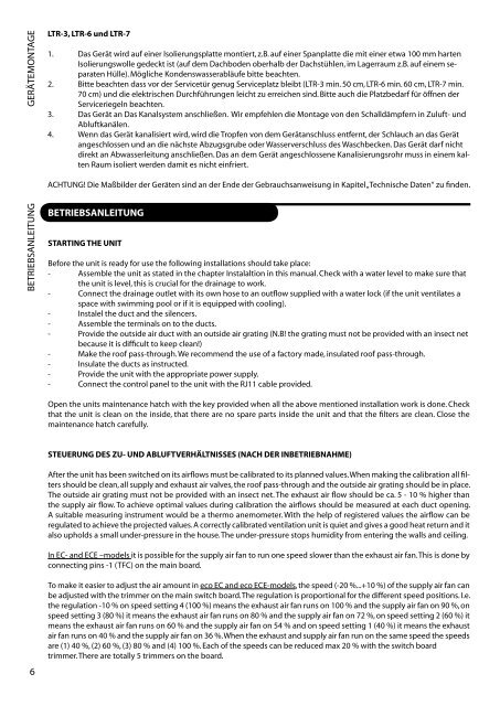
1. Das Gerät wird auf einer Isolierungsplatte montiert, z.B. auf einer Spanplatte die mit einer etwa 100 mm harten<br />
Isolierungswolle gedeckt ist (auf dem Dachboden oberhalb der Dachstühlen, im Lagerraum z.B. auf einem se-<br />
paraten Hülle). Mögliche Kondenswasserabläufe bitte beachten.<br />
. Bitte beachten dass vor der Servicetür genug Serviceplatz bleibt (LTR-3 min. 50 cm, LTR-6 min. 60 cm, LTR-7 min.<br />
70 cm) und die elektrischen Durchführungen leicht zu erreichen sind. Bitte auch die Platzbedarf für öffnen der<br />
Serviceriegeln beachten.<br />
3. Das Gerät an Das Kanalsystem anschließen. Wir empfehlen die Montage von den Schalldämpfern in Zuluft- und<br />
Abluftkanälen.<br />
4. Wenn das Gerät kanalisiert wird, wird die Tropfen von dem Gerätanschluss entfernt, der Schlauch an das Gerät<br />
angeschlossen und an die nächste Abzugsgrube oder Wasserverschluss des Waschbecken. Das Gerät darf nicht<br />
direkt an Abwasserleitung anschließen. Das an dem Gerät angeschlossene Kanalisierungsrohr muss in einem kal-<br />
ten Raum isoliert werden damit es nicht einfriert.<br />
ACHTUNG! Die Maßbilder der Geräten sind an der Ende der Gebrauchsanweisung in Kapitel „Technische Daten“ zu finden.<br />
BETRIEBSANLEITUNG<br />
STARTING THE UNIT<br />
Before the unit is ready for use the following installations should take place:<br />
- Assemble the unit as stated in the chapter Instalaltion in this manual. Check with a water level to make sure that<br />
the unit is level, this is crucial for the drainage to work.<br />
- Connect the drainage outlet with its own hose to an outflow supplied with a water lock (if the unit ventilates a<br />
space with swimming pool or if it is equipped with cooling).<br />
- Instalel the duct and the silencers.<br />
- Assemble the terminals on to the ducts.<br />
- Provide the outside air duct with an outside air grating (N.B! the grating must not be provided with an insect net<br />
because it is difficult to keep clean!)<br />
- Make the roof pass-through. We recommend the use of a factory made, insulated roof pass-through.<br />
- Insulate the ducts as instructed.<br />
- Provide the unit with the appropriate power supply.<br />
- Connect the control panel to the unit with the RJ11 cable provided.<br />
Open the units maintenance hatch with the key provided when all the above mentioned installation work is done. Check<br />
that the unit is clean on the inside, that there are no spare parts inside the unit and that the filters are clean. Close the<br />
maintenance hatch carefully.<br />
STEUERUNG DES ZU- UND ABLUFTVERHÄLTNISSES (NACH DER INBETRIEBNAHME)<br />
After the unit has been switched on its airflows must be calibrated to its planned values. When making the calibration all filters<br />
should be clean, all supply and exhaust air valves, the roof pass-through and the outside air grating should be in place.<br />
The outside air grating must not be provided with an insect net. The exhaust air flow should be ca. 5 - 10 % higher than<br />
the supply air flow. To achieve optimal values during calibration the airflows should be measured at each duct opening.<br />
A suitable measuring instrument would be a thermo anemometer. With the help of registered values the airflow can be<br />
regulated to achieve the projected values. A correctly calibrated ventilation unit is quiet and gives a good heat return and it<br />
also upholds a small under-pressure in the house. The under-pressure stops humidity from entering the walls and ceiling.<br />
In EC- and ECE –models it is possible for the supply air fan to run one speed slower than the exhaust air fan. This is done by<br />
connecting pins -1 (TFC) on the main board.<br />
To make it easier to adjust the air amount in eco EC and eco ECE-models, the speed (- 0 %...+10 %) of the supply air fan can<br />
be adjusted with the trimmer on the main switch board. The regulation is proportional for the different speed positions. I.e.<br />
the regulation -10 % on speed setting 4 (100 %) means the exhaust air fan runs on 100 % and the supply air fan on 90 %, on<br />
speed setting 3 (80 %) it means the exhaust air fan runs on 80 % and the supply air fan on 7 %, on speed setting (60 %) it<br />
means the exhaust air fan runs on 60 % and the supply air fan on 54 % and on speed setting 1 (40 %) it means the exhaust<br />
air fan runs on 40 % and the supply air fan on 36 %. When the exhaust and supply air fan run on the same speed the speeds<br />
are (1) 40 %, ( ) 60 %, (3) 80 % and (4) 100 %. Each of the speeds can be reduced max 0 % with the switch board<br />
trimmer. There are totally 5 trimmers on the board.


