13.48 Bewades P 2011-08.pmd - BWT
13.48 Bewades P 2011-08.pmd - BWT
13.48 Bewades P 2011-08.pmd - BWT
- TAGS
- bewades
- www.bwt.de

Erfolgreiche ePaper selbst erstellen
Machen Sie aus Ihren PDF Publikationen ein blätterbares Flipbook mit unserer einzigartigen Google optimierten e-Paper Software.
Be <strong>Bewades</strong> Be ades ® P<br />
P<br />
UV-Desinfektionsanlagen UV-Desinfektionsanlagen für für den den Einsatz Einsatz Einsatz im im Reinstwasserbereich<br />
Reinstwasserbereich<br />
Typen: Typen: 130W130/17 130W130/17 P, P, 390W130/27 390W130/27 P, P, 520W130/35 520W130/35 520W130/35 P P (Grössere (Grössere (Grössere Anlagen Anlagen auf auf Anfrage)<br />
Anfrage)<br />
<strong>Bewades</strong> P<br />
Verw erw erw erwendungszw<br />
erw endungszw<br />
endungszwec<br />
endungszw ec eck ec<br />
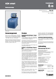
Die <strong>Bewades</strong> UV-Anlage in Pharmaausführung<br />
(„P“) dient zur Desinfektion und Restozonvernichtung<br />
in Reinstwasserkreisläufen der<br />
Pharmazie, Kosmetik, Medizintechnik und<br />
Halbleiterproduktion.<br />
Die UV-Anlagen in Pharmaausführung sind<br />
speziell für dieses Einsatzgebiet konzipiert,<br />
insbesondere sind alle medienberührenden<br />
Teile in Stahlqualität 1.4404 (entspricht 316 L)<br />
ausgeführt und elektropoliert (Rauhtiefe<br />
< 0,5 μm).<br />
Pr Prinzip Pr inzip der der UV UV-Desinf UV -Desinf -Desinfektion<br />
-Desinf ektion<br />
Bei der UV-Desinfektion wird die zu desinfizierende<br />
Flüssigkeit mit einem speziellen Quecksilber<br />
Niederdruckstrahler bestrahlt. Dieser<br />
Strahler ist so ausgelegt, dass er mit hohem<br />
Wirkungsgrad UVC-Strahlung von 254 nm<br />
Wellenlänge erzeugt.<br />
Die in allem Lebenden vorkommende DNA hat<br />
ihr Absorptionsmaximum nahe bei dieser Wellenlänge.<br />
Wird die DNA mit Strahlung von 254<br />
nm Wellenlänge bestrahlt, so wird eine photochemische<br />
Reaktion induziert und die DNA<br />
inaktiviert. Dadurch kommt der Stoffwechsel<br />
in den Keimen zum Erliegen, die Vermehrungsfähigkeit<br />
ist nicht mehr gegeben, der<br />
Keim ist also unschädlich gemacht worden.<br />
Um die Desinfektion sicherzustellen ist eine<br />
Mindestdosis an UVC-Strahlung erforderlich.<br />
In den meisten Fällen ist eine Dosis von 300 -<br />
400 J/m 2 ausreichend.<br />
www.bwt.de<br />
www.bwt.de<br />
Funktion Funktion<br />
Funktion<br />
Das zu behandelnde Wasser fliesst durch die<br />
Edelstahlbestrahlungskammer (1). Die UV-<br />
Strahler erzeugen eine für die Desinfektion<br />
besonders wirksame UVC-Strahlung von 254 nm<br />
Wellenlänge. Durch diese UVC-Strahlung werden<br />
die im Wasser vorhandenen Keime sicher abgetötet.<br />
Bei der Restozonvernichtung baut die UVC-<br />
Strahlung von 254 nm Wellenlänge das im<br />
Wasser gelöste Ozon mit hohem Wirkungsgrad<br />
ab.<br />
Die Anlagenüberwachung und -steuerung erfolgt<br />
mit der prozessorgesteuerten UV-<br />
UV-<br />
Control Control II II, II die in einen Schaltschrank (3) integriert<br />
ist.<br />
Der UVC-Sensor überwacht die Strahleralterung,<br />
die Bestrahlungsstärke sowie eine<br />
eventuelle Belagbildung auf den Strahlerschutzrohren.<br />
Hinweis Hinweis: Hinweis Die Leistung von UVC- Strahlern ist<br />
temperaturabhängig. Daher sind geringfügige<br />
Schwankungen in der Anzeige je nach Wassertemperatur<br />
oder Erwärmung bei Stillstand<br />
normal.<br />
Produktdatenblatt<br />
Produktdatenblatt<br />
13<br />
13<br />
<strong>13.48</strong> .48<br />
1-534 052<br />
Aktuelle Fassung vom August August August <strong>2011</strong><br />
<strong>2011</strong><br />
ersetzt alle bisherigen Fassungen<br />
Projektierung Projektierung der der der Anlagen Anlagen<br />
Anlagen<br />
Um einen störungsfreien, sicheren Betrieb der<br />
Anlagen zu gewährleisten, ist eine Fachberatung<br />
erforderlich.<br />
Wichtigster Punkt bei der Projektierung ist die<br />
Bestimmung der UV-Transmission des zu<br />
behandelnden Wassers. Sie ist je nach Art und<br />
Herkunft des Wassers verschieden und kann<br />
je nach Witterungsverhältnissen schwanken.<br />
Nach der Grösse der Transmission und dem<br />
maximal benötigten Durchfluss richtet sich der<br />
erforderliche Gerätetyp.<br />
Wenn der Durchfluss nicht durch die am Einbauort<br />
gegebenen Bedingungen auf den maximal<br />
zulässigen Wert begrenzt werden kann<br />
(z.B. Pumpenförderleistung oder Grösse und<br />
Anzahl der Zapfstellen), muss eine zusätzliche<br />
Drossel eingebaut werden.<br />
Je nach Einsatzfall sind an geeigneter Stelle<br />
abflammbare Probenahmehähne vorzusehen.<br />
Unter Umständen ist eine Voraufbereitung des<br />
Wassers notwendig, z.B. durch Enteisenung<br />
oder Entmanganung, Einbau eines Aktivkohlefilters<br />
oder einer Mikrofiltration. Je nach Betriebsbedingungen<br />
und Wasserqualität kann<br />
zur Verhinderung von Ablagerungen auf den<br />
Strahlerschutzrohren auch eine Teilenthärtung<br />
vorgesehen werden.
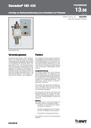
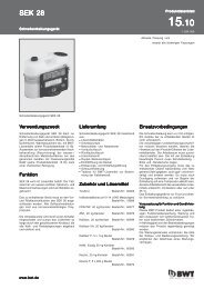
Lief Liefer Lief er erumf erumf<br />
umf umfang umf ang<br />
1 Bestrahlungskammer aus Edelstahl (316 L)<br />
Clampanschluss (DIN 32676)<br />
2 UVC-Sensor<br />
3 Schaltkasten mit Vorschalteinheiten für<br />
die Strahler<br />
4 Elektronische Steuerung UV-Control II<br />
- Strahlerschutzrohre aus hochwertigem<br />
Quarz<br />
- Leistungsstarke 130W UVC-Niederdruckstrahler<br />
- erwartete Strahlerlebensdauer 10000 -<br />
14000 Betriebsstunden<br />
- UV-Überwachung mit kalibrierbarem UVC-<br />
Sensor<br />
- Schaltschrank mit prozessorgesteuerter<br />
Elektronik mit:<br />
Betriebsstundenzähler<br />
Zählung der Strahlereinschaltungen<br />
digitaler Anzeige der Bestrahlungsstärke<br />
Anschlussmöglichkeit für Absperrventil,<br />
Spülventil und Durchflusskontroller<br />
einstellbare Spül- und Wartezeiten<br />
Strahlerüberwachung<br />
0/4 - 20 mA Ausgang der Bestrahlungsstärke<br />
ZLT-Störmeldungsrelais<br />
Warnschwelle mit Meldung über ZLT-Kontakt<br />
Ferneinschaltung<br />
Optional:<br />
Optional:<br />
- Rauhtiefenprotokoll<br />
- Strömungswächter- und Durchflussmessereinheit<br />
- Kalibrierzertifikat des Sensors<br />
Verbrauchsmaterial<br />
Verbrauchsmaterial<br />
- Ersatzstrahler Bestell-Nr.: 23936<br />
- Filtermatte für Schaltschranklüfter<br />
Bestell-Nr.: 1-902451<br />
- O-Ringset Bestell-Nr.: 2-060928<br />
4<br />
3<br />
2<br />
1<br />
Einbauvorbedingungen<br />
Einbauvorbedingungen<br />
Um einen störungsfreien, sicheren Betrieb der<br />
Anlage zu gewährleisten, ist eine Fachberatung<br />
erforderlich.<br />
Hierbei erfolgt die Bestimmung der Auslegetransmission<br />
des zu behandelnden Wassers sowie<br />
die Festlegung der benötigten Betriebsparameter.<br />
Die in den technischen Daten genannten<br />
Volumenströme beziehen sich auf die Restozonvernichtung.<br />
Eine Desinfektion ist bei Einhaltung dieser<br />
Volumenströme und einer UV-Transmission<br />
von grösser 90 % /10 cm gewährleistet.<br />
Bei vollentsalztem Wasser kann von einer UV-<br />
Transmission von 90% / 10 cm ausgegangen<br />
werden.<br />
Restozonvernichtung: Abbau von max. 0,2<br />
ppm Ozon um 98 %.<br />
Örtliche Installationsvorschriften, allgemeine<br />
Richtlinien und die technischen Daten müssen<br />
beachtet werden.<br />
Der Aufstellungsort muss frostsicher sein und<br />
den Schutz der Anlage vor Chemikalien, Farbstoffen,<br />
Lösungsmitteln und Dämpfen gewährleisten.<br />
Die Umgebungstemperatur sowie die<br />
Abstrahlungstemperatur in unmittelbarer Nähe<br />
dürfen 40°C nicht überschreiten.<br />
Wenn kein Bodenablauf vorhanden ist, muss<br />
eine separate Sicherheitseinrichtung (z.B.<br />
Wasserstopp) eingesetzt werden.<br />
Oberhalb der Anlage ist für den Strahlerwechsel<br />
ein Freiraum von ca. 1,0 m notwendig.<br />
Voraussetzung Voraussetzung für für für Funktion Funktion und und Gewährleis-<br />
GewährleisGewährleis-<br />
tung<br />
tung<br />
UV-Geräte bedürfen einer regelmässigen<br />
Funktionsüberwachung, Wartung und dem<br />
Austausch von funktionsrelevanten Teilen<br />
nach bestimmten Zeitintervallen.<br />
Eine Überprüfung der elektrischen Sicherheit<br />
nach BGV A2 VGB 4 ist alle 4 Jahre erforderlich.<br />
UV-Geräte müssen in Abhängigkeit von den<br />
Betriebsbedingungen regelmässig gereinigt<br />
werden.<br />
Die Wartungsintervalle entnehmen Sie bitte<br />
der Einbau- und Bedienungsanleitung. Wir<br />
empfehlen den Abschluss eines Wartungsvertrages.
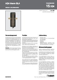
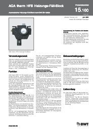
Abmessungen<br />
Abmessungen<br />
Abmessungen<br />
<strong>Bewades</strong> <strong>Bewades</strong><br />
130W130/17 130W130/17 P P<br />
390W130/27 390W130/27 P P<br />
520W130/35 520W130/35 520W130/35 P<br />
P<br />
A mm 168 273 356<br />
B mm 1170 1217 1265<br />
C mm 131 146 168<br />
D mm 500 500 500<br />
E mm 180 275 290<br />
F mm 220 315 330<br />
G mm 65 80 80<br />
H mm 250 250 250<br />
G<br />
Freiraum Freiraum für für Strahlerwechsel<br />
Strahlerwechsel<br />
1050 1050 mm<br />
mm<br />
H<br />
D<br />
A<br />
F<br />
E<br />
C<br />
B<br />
4x d11<br />
Sensorlage<br />
130W130/17P<br />
390W130/27P<br />
520W130/35P<br />
45°
Technische echnische Daten<br />
Daten<br />
<strong>Bewades</strong> <strong>Bewades</strong><br />
Typ Typ 130W130/17 130W130/17 P P 390W130/27 390W130/27 P P<br />
520W130/35 520W130/35 P<br />
P<br />
Anschluss Clampflansch nach DIN 32676<br />
Eingang DN 32 50 65<br />
Ausgang DN 32 50 65<br />
Einbaulage vertikal<br />
Ausführung zur Wandbefestigung<br />
Dichtungsmaterial EPDM<br />
Werkstoff - UV-Bestrahlungskammer mediumberührt 1.4404 (316 L),<br />
Oberfläche, innen Ra < 0,5 μm, elektropoliert<br />
Sanitisierung 1 h bei 85 °C<br />
Max. Volumenstrom T = 90% * *<br />
100 m3 /h 4 18 30<br />
Max. Betriebsdruck bar 10 bei 30° C<br />
Wassertemperatur min./max. °C 5/30 (bei Temperaturen über 20 °C ist Fachberatung erforderlich)<br />
Umgebungstemperatur min./max. °C 5/40<br />
Anzahl der Strahler 1 3 4<br />
Anschlussleistung pro Strahler W 130<br />
Erwartete Strahlerlebensdauer h 10000 - 14000<br />
UVC-Leistung (nach 100 Betriebsstunden) W 52 3 x 52 4 x 52<br />
Netzanschluss V/Hz 230/50; Option 60 Hz<br />
Anschlussleistung W 160 420 550<br />
Intensitätssensor mit 10 m Kabel<br />
Steuerung extern und vor Ort einschaltbar<br />
Ausgangasignal 4 - 20 mA bzw. 0 - 20 mA<br />
Schaltschrank mit Wandbefestigung Stalhl, kunststoffbeschichtet<br />
Schutzart IP 54<br />
Abmessungen Schaltschrank B x H x T mm 380 x 600 x 210<br />
Bestell-Nr.: Bestell-Nr.:<br />
23285 23285<br />
23286 23286<br />
23287<br />
23287<br />
* * * Die Einhaltung der oben stehenden Betriebsdaten stellt eine Inaktivierung pathogener Bakterien (5 bis 6 log Stufen) sowie einen<br />
98 %-igen Ozonabbau bei einer Ozoneingangskonzentration von 0,2 ppm sicher.<br />
Dokumentation:<br />
Dokumentation:<br />
Einbau- und Bedienungsanleitung<br />
Behälterzeugnis nach DIN EN 10204 - 3.1, mediumberürte Teile<br />
E-Pläne Schaltkasten mit Schaltschrankansicht<br />
Schweisser-Prüfbescheinigung<br />
Zertifikate der EPDM O-Ringe (FDA/USP class VI)<br />
Rauhigkeitszertifikat < 0,5 μm (2.2 DIN EN 10204)<br />
<strong>BWT</strong> <strong>BWT</strong> Austria Austria GmbH GmbH • • Walter-Simmer-Strasse Walter-Simmer-Strasse • • A-5310 A-5310 Mondsee Mondsee • • Tel. Tel. 06232 06232 06232 / / 5010 5010 0 0 • • • FAX FAX 06232 06232 / / 4058<br />
4058<br />
<strong>BWT</strong> <strong>BWT</strong> Wassertechnik Wassertechnik GmbH GmbH • • • Industriestrasse Industriestrasse • • • D-69198 D-69198 Schriesheim Schriesheim • • Tel. Tel. 06203 06203 / / 73 73 0 0 • • • FAX FAX 06203 06203 / / 73 73 102<br />
102<br />
Produktdatenblatt / © <strong>BWT</strong> Wassertechnik GmbH / Printed in Germany / Änderungen vorbehalten
<strong>Bewades</strong> <strong>Bewades</strong>®<br />
P<br />
P<br />
UV UV disinfection disinfection unit unit for for use use in in the the field field of of pure pure pure water<br />
water<br />
Types: Types: 130W130/17 130W130/17 130W130/17 P, P, 390W130/27 390W130/27 P, P, 520W130/35 520W130/35 P P (Larger (Larger units units units on on request) request)<br />
request)<br />
<strong>Bewades</strong> P<br />
Intended Intended use<br />
use<br />
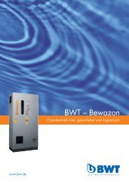
The <strong>Bewades</strong> UV unit in pharmaceutical design<br />
("P“) is used for disinfection and elimination of<br />
residual ozone in ultrapure water circuits in the<br />
pharmaceutical, cosmetic and medical<br />
engineering industries and semiconductor<br />
production.<br />
The UV systems in pharmaceutical design are<br />
especially designed for this field of use; in<br />
particular, all components that come into contact<br />
with media are in steel quality 1.4404<br />
(corresponding to 316 L) and electroplated<br />
(surface finish < 0.8 μm).<br />
Principle Principle of of UV UV Disinfection<br />
Disinfection<br />
During the UV disinfection procedure, the liquid<br />
being disinfected is irradiated with a special<br />
mercury low-pressure emitter. This emitter is<br />
designed in such a way that it produces UVC<br />
radiation of 254 nm wavelength with a high<br />
degree of efficiency.<br />
The DNA, which occurs in all living things, has<br />
its absorption maximum near to this wavelength.<br />
If the DNA is irradiated with radiation of 254 nm<br />
wavelength, then a photochemical reaction is<br />
induced and the DNA is deactivated. As a result,<br />
the metabolism in the germs comes to a standstill,<br />
the ability to reproduce no longer exists, the<br />
germ has, thus, been made harmless.<br />
To guarantee disinfection, a minimum dose of<br />
UVC radiation is required. In most cases, a dose<br />
of 300 - 400 J/m 2 is sufficient.<br />
www.bwt.de<br />
www.bwt.de<br />
www.bwt.de<br />
Function<br />
Function<br />
The water being treated flows through the<br />
stainless steel radiation chamber (1). The UV<br />
emitters produce a UVC radiation of 254 nm<br />
wavelength, which is particularly effective for<br />
disinfection. Through this UVC radiation, the<br />
germs that exist in the water are safely killed.<br />
During the elimination of the residual ozone, the<br />
UVC radiation of 254 nm wavelength reduces<br />
the ozone dissolved in the water with a high<br />
degree of efficiency.<br />
The unit control and monitoring is carried out by<br />
the processor controlled UV-Control UV-Control II II, II which<br />
is integrated into the switching cabinet (3).<br />
The UVC sensor monitors the emitter’s aging,<br />
the irradiated UV intensity into the water being<br />
treated and any possible build-up of any coating<br />
on the emitter protective tubes.<br />
Note: The performance of UVC emitters depends<br />
on the temperature. For this reason, slight<br />
deviations in the display are normal depending<br />
on the water temperature or heating during a<br />
standstill.<br />
Product Product data data sheet<br />
sheet<br />
13<br />
13<br />
Design Design Design of of the the units<br />
units<br />
<strong>13.48</strong> .48<br />
To ensure flawless, safe operation of the unit,<br />
specialist consultation is necessary.<br />
The most important point when planning the unit<br />
is to determine the UV transmission of the water<br />
being treated. Depending on the type and origin<br />
of the water, this can differ and can deviate<br />
depending on the atmospheric conditions.<br />
The necessary unit type depends on the size of<br />
the transmission and the maximum required<br />
flow rate.<br />
If the flow rate cannot be restricted to the<br />
maximum permitted value through the conditions<br />
at the site of installation (e.g. pump capacity or<br />
size and number of extraction points), then an<br />
additional restrictor must be installed.<br />
Depending on the usage, flame-cleaned sample<br />
taps must be provided in a suitable position.<br />
Under certain circumstances, pre-treatment of<br />
the water is necessary, e.g. through deferrisation<br />
or demanganisation, installation of an activated<br />
charcoal filter or microfiltration. Depending on<br />
the operating conditions and water quality, partial<br />
softening may also be necessary to prevent<br />
deposits on the emitter protective tubes.
Scope Scope of of Delivery<br />
Delivery<br />
1 Radiation chamber made of stainless steel<br />
(316 L)<br />
Stainless steeI turbulators built into radiation<br />
chamber (316 L)<br />
Clamp connection (DIN 32676)<br />
2 UVC-Sensor<br />
3 Switching cabinet with series units for the<br />
emitter<br />
4 Electronic control UV-Control II<br />
- Emitter protective tube made of high quality<br />
quartz<br />
- High performance 130W UVC low-pressure<br />
emitters<br />
- Expected emitter service life of 10000 - 14000<br />
operating hours<br />
- UV monitoring with UVC-Sensor which can<br />
be calibrated<br />
- Processor-controlled electronic unit<br />
including:<br />
Running time meter<br />
Emitter actuation counter<br />
Digital display of emission strength<br />
Connection of shut-off valve, rinsing valve<br />
and flow control possible<br />
Programmable rinse and waiting times<br />
Emitter monitor<br />
0/4 - 20 mA output for radiation strength<br />
central control unit error message relay<br />
Warning threshold with message given by<br />
CIC contact<br />
Fine tuning<br />
Optional:<br />
Optional:<br />
- Anlagen in bedämpfbarer Ausführung<br />
- Surface finish protocol<br />
- Flow monitor and flow through meter.<br />
Expendableparts<br />
Expendableparts<br />
- Replacement emitter Order no.: 23936<br />
- Filter mat for switching cabinet vent<br />
Order no.: 1-902451<br />
4<br />
3<br />
2<br />
1<br />
Installation Installation conditions<br />
conditions<br />
In order to guarantee fault-free, safe operation<br />
of the <strong>Bewades</strong> unit, technical consultation is<br />
required before installation. During the<br />
consultation, the rated transmission of the water<br />
to be treated is determined and the operating<br />
parameters required are set.<br />
The volume flows mentioned in the technical<br />
data are related to the elimination of residual<br />
ozone.<br />
When complying with these volume flows and<br />
a UV transmission of more than 90 % /10 cm,<br />
disinfection is guaranteed.<br />
For fully demineralised water, a UV transmission<br />
of 90% / 10 cm can be assumed.<br />
Elimination of residual ozone: Decomposition of<br />
max. 0.2 ppm ozone by 98 %.<br />
Heed the local installation regulations, general<br />
guidelines and technical data.<br />
The installation site must be free of frost and kept<br />
free of chemicals, paint, solvents and fumes.<br />
Neither the ambient temperature nor the radiation<br />
temperature may exceed 40 °C in the immediate<br />
vicinity.<br />
If no floor drain is available, then a separate<br />
safety unit (e.g. water stop) must be used.<br />
A clearance of approx. 1.0 m must be provided<br />
above the unit for changing emitters.<br />
Before a damping of the unit, the sensor must<br />
be removed (danger of destruction)<br />
Prerequisite Prerequisite for for Function Function and and Guarantee<br />
Guarantee<br />
Ozone systems require regular functional<br />
monitoring, maintenance and the replacement<br />
of functionally relevant components after<br />
predefined periods of time.<br />
UV units must be cleaned regularly subject to<br />
the operating conditions.<br />
Inspection of electrical safety is required every<br />
4 years in accordance with BGV A2 VGB 4.<br />
Please see the installation and operating<br />
instructions for information on maintenance<br />
intervals. We recommend concluding a<br />
maintenance contract.
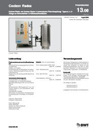
Dimensions<br />
Dimensions<br />
<strong>Bewades</strong> <strong>Bewades</strong><br />
130W130/17 130W130/17 P P<br />
390W130/27 390W130/27 P P<br />
520W130/35 520W130/35 520W130/35 P<br />
P<br />
A mm 168 273 356<br />
B mm 1170 1217 1265<br />
C mm 131 146 168<br />
D mm 500 500 500<br />
E mm 180 275 290<br />
F mm 220 315 330<br />
G mm 65 80 80<br />
H mm 250 250 250<br />
G<br />
Clearance Clearance for for emitter emitter exchange<br />
exchange<br />
1050 1050 1050 mm<br />
mm<br />
H<br />
D<br />
A<br />
F<br />
E<br />
C<br />
B<br />
4x d11<br />
Sensorlage<br />
130W130/17P<br />
390W130/27P<br />
520W130/35P<br />
45°
Technical echnical data data<br />
data<br />
<strong>Bewades</strong> <strong>Bewades</strong><br />
Type Type Type 130W130/17 130W130/17 P P 390W130/27 390W130/27 P P<br />
520W130/35 520W130/35 520W130/35 P<br />
P<br />
Connection clamping flange in acc. with DIN 32676<br />
Inlet DN 32 50 65<br />
Outlet DN 32 50 65<br />
Installation length vertical<br />
Version with wall bracket<br />
Sealing material EPDM with conformity declaration in acc. with FDA<br />
UV radiation chamber medium contact 1.4404 (316 L), Option 1.4435 all parts that come into<br />
contact with the medium are orbitally<br />
welded with certified welding equipment and have a welding report<br />
Surface, in Ra < 0.8 μm, electro polished, dead room< 3d<br />
Option surface finish report<br />
Damping can be damped with 127.4° C at 2.5 bar absolute, 30 min with sensor removed<br />
Outlet nominal width DN 25 40 65<br />
Max. flow rate T = 90% * *<br />
100 m3 /h 4 18 30<br />
Max. operating pressure bar 10 bei 30° C<br />
Water temperature min./max. °C 5/30 (at temps over 20 °C, professional consultation is required)<br />
Ambient temperature min./max. °C 5/40<br />
Number of emitters 1 3 4<br />
Connection power per emitter W 130<br />
Expected service life of emitter h 10000 - 14000<br />
UVC power (after 100 operating hours) W 52 3 x 52 4 x 52<br />
Power supply V/Hz 230/50; Option 60 Hz<br />
Power supply capacity W 160 420 550<br />
Intensity sensor with 6 m cable<br />
Control external and on site activation<br />
Outlet signal 4 - 20 mA or 0 - 20 mA<br />
Switching cabinet with wall bracket St/Ral......<br />
Option Stainless steel, matt smoothed<br />
Protection class IP 54<br />
Dimensions switching cabinet B x H x T mm 380 x 600 x 210<br />
Order Order no.: no.:<br />
23285 23285<br />
23286 23286<br />
23287 23287<br />
23287<br />
* Compliance with the abovementioned operating data ensures a deactivation of pathogenic bacteria (5 to 6 log stages) as well as a 98 % ozone<br />
reduction at an ozone outlet concentration of 0.2 ppm.<br />
Documentation:<br />
Documentation:<br />
Installation and operating instructions<br />
Approval certificate in acc. DIN EN 10204 - 3.1, parts in contact with medium<br />
Calibration certificate, UV sensor<br />
E plans switching cabinet with switching cabinet view<br />
Isometric or welding plan with labelling of the welding seams<br />
<strong>BWT</strong> <strong>BWT</strong> Austria Austria GmbH GmbH • • Walter-Simmer-Strasse Walter-Simmer-Strasse • • A-5310 A-5310 A-5310 Mondsee Mondsee • • Tel. Tel. 06232 06232 06232 / / 5010 5010 0 0 • • FAX FAX 06232 06232 06232 / / 4058<br />
4058<br />
<strong>BWT</strong> <strong>BWT</strong> Wassertechnik Wassertechnik GmbH GmbH GmbH • • • Industriestrasse Industriestrasse • • • D-69198 D-69198 Schriesheim Schriesheim Schriesheim • • Tel. Tel. 06203 06203 / / 73 73 0 0 • • FAX FAX 06203 06203 06203 / / 73 73 102<br />
102<br />
Product data sheet / © <strong>BWT</strong> Wassertechnik GmbH / Printed in Germany / Changes reserved!