Uni Standard - Layher
Uni Standard - Layher
Uni Standard - Layher

Create successful ePaper yourself
Turn your PDF publications into a flip-book with our unique Google optimized e-Paper software.
6<br />
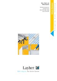
Assembly <strong>Layher</strong> <strong>Uni</strong> <strong>Standard</strong> Tower<br />
A1 Pay attention to the General Assembly and Use Instructions on page 24. The examples shown of the tower types 1108 – 1111, 1128 – 1131, 1208 – 1211 are<br />
designed for use indoors. According to the regulations in force since January 1st 1987, the permissible maximum platform height outdoors is 8 m.<br />
Pay attention to the parts list and ballasting tables on pages 11–13.<br />
A2 Basic assembly<br />
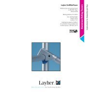
A2.1 Tower Model<br />
1101<br />
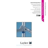
A2.2 Tower Models<br />
1102 – 1106<br />
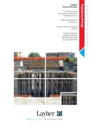
A2.3 Tower Models<br />
1107 – 1111,<br />
1115, 1116<br />
l3<br />
l1<br />
l2<br />
l6<br />
l1<br />
l6<br />
l6<br />
l11<br />
l1<br />
l1<br />
l7<br />
l9<br />
l1<br />
l10<br />
l10<br />
l7<br />
l10<br />
l8<br />
l7<br />
l8<br />
l1<br />
l8<br />
l8<br />
l5<br />
l7<br />
l1<br />
Õ<br />
Access side<br />
l5<br />
l6<br />
l6<br />
l6<br />
l11<br />
l1<br />
l1<br />
l11<br />
l2<br />
l3<br />
l1<br />
1. The castors l1 of the tower type 1101 are inserted<br />
into the ladder frame l6 and secured against falling<br />
out by fastening the wing screws on the spindle nuts.<br />
2. Connect both ladder frames l6 with 2 Double<br />
guardrails l9 . Clip the access deck l10 onto the 4th<br />
ladder l6 rung from the bottom. The snap-on claws<br />
of all parts are to be locked onto the ladder rungs<br />
from above.<br />
3. A three-part side guard must be provided if<br />
required by the valid provisions applying for the work<br />
to be performed.<br />
1. Insert the castors l1 into the mobile beam l2<br />
and secure against falling out by fastening the wing<br />
screws on the spindle nuts.<br />
2. Connect the mobile beams l2 using a base strut l5<br />
and a guardrail l7 .<br />
3. Mount the two ladder frames l6 and secure with<br />
spring clips l11 .<br />
4. Mount both diagonal braces l8 to the inside<br />
of the deck claws and push them outwards as<br />
far as possible in order to brace the ladder<br />
frames l6 .<br />
Tower types 1115 and 1116 with adjustable mobile<br />
beam l3 are intended for outdoor use.<br />
1. Insert the castors l1 into the adjustable mobile<br />
beam l3 and secure them against falling out by<br />
fastening the wing screws on the spindle nuts.<br />
2. Fix the base strut l5 to the deck supports of the<br />
adjustable mobile beam l3 and mount the guardrail l7<br />
onto the deck supports.<br />
3. Add two ladder frames l6 and secure with spring<br />
clips l11 .<br />
4. Mount both diagonal braces l8 inside the<br />
deck claws and push them outwards as far as<br />
possible in order to brace the ladder frames l6 .<br />
In order to remove the different parts, depress<br />
the locking clips of the snap-on claws. The red<br />
claws on the deck enable a single person to<br />
assemble or dismantle them easily; open them at<br />
one end and rest the base of the clips on the<br />
rung. Now open the opposite clips and remove<br />
the deck.<br />
Level the tower using the threaded spindles.<br />
5. For tower models 1102, 1105 and 1106 only,<br />
an access deck l10 has to be placed on the eighth rung<br />
of the ladder frame l6 .<br />
6. Level the tower using the threaded spindles.<br />
For the following assembly steps, tower types 1102<br />
and 1103 see chapter 5; for tower models 1104–1106<br />
see chapter 4.<br />
5. For tower types 1115, 1116, 1109 and 1110, install<br />
an access deck l10 on the 8th rung of the ladder<br />
frame l6 .<br />
6. On tower types 1107, 1108 and 1111 mount two<br />
guardrails l7 on the 8th rung. No access deck l10 is<br />
necessary.<br />
7. The horizontal gap between two decks or between<br />
decks and ledgers must not exceed 25 mm.<br />
8. Level the tower using the threaded spindles.<br />
For the following assembly steps see chapter 4.