Uni Standard - Layher
Uni Standard - Layher
Uni Standard - Layher

Create successful ePaper yourself
Turn your PDF publications into a flip-book with our unique Google optimized e-Paper software.
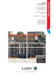
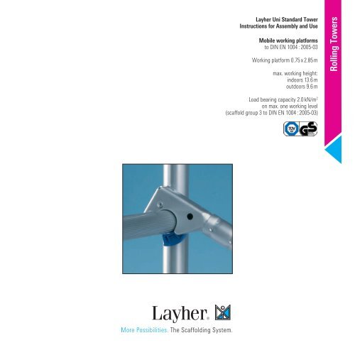
<strong>Layher</strong> <strong>Uni</strong> <strong>Standard</strong> Tower<br />
Instructions for Assembly and Use<br />
Mobile working platforms<br />
to DIN EN 1004:2005-03<br />
Working platform 0.75 x 2.85 m<br />
max. working height:<br />
indoors 13.6 m<br />
outdoors 9.6 m<br />
Load bearing capacity 2.0 kN/m 2<br />
on max. one working level<br />
(scaffold group 3 to DIN EN 1004:2005-03)<br />
Rolling Towers
2<br />
Tower Types <strong>Layher</strong> <strong>Uni</strong> <strong>Standard</strong> Tower<br />
For outdoor use observe height limits.<br />
Tower Models<br />
1101 – 1106<br />
Tower Model 1101 1102 1103 1104 1105 1106<br />
Working height (m) 3.5 4.5 5.5 6.5 7.5 8.5<br />
Scaffold height 1) (m) 2.6 (2.45) 3.75 (3.60) 4.75 (4.60) 5.75 (5.60) 6.75 (6.60) 7.75 (7.60)<br />
Platform height (m) 1.5 2.5 3.5 4.5 5.5 6.5<br />
Weight (kg) [without ballast] 86.0 163.9 173.3 189.7 242.3 251.5<br />
Tower Models<br />
1107 – 1111<br />
1) Values in brackets: minimum tower height incl. spigots.<br />
Tower Model 1107 1108 1109 1110 1111<br />
Working height (m) 9.6 10.6 11.6 12.6 13.6<br />
Scaffold height 1) (m) 8.79 (8.64) 9.79 (9.64) 10.79 (10.64) 11.79 (11.64) 12.79 (12.64)<br />
Platform height 7.6 8.6 9.6 10.6 11.6<br />
Weight (kg) [without ballast] 326.5 335.7 388.3 397.5 421. 3<br />
1) Values in brackets: minimum tower height incl. spigots.
Tower models with stabilizers, extendable <strong>Layher</strong> <strong>Uni</strong> <strong>Standard</strong> Tower<br />
For outdoor use observe height limits.<br />
Tower Models<br />
1124 – 1127<br />
Tower Model 1124 1125 1126 1127<br />
Working height (m) 6.5 7.5 8.5 9.5<br />
Scaffold height 1) (m) 5.7 (5.45) 6.7 (6.45) 7.7 (7.45) 8.7 (8.45)<br />
Platform height (m) 4.5 5.5 6.5 7.5<br />
Weight (kg) [without ballast] 198.3 250.9 260.1 283.9<br />
Tower Models<br />
1128 – 1131<br />
1) Values in brackets: minimum tower height incl. spigots.<br />
Tower Model 1128 1129 1130 1131<br />
Working height (m) 10.5 11.5 12.5 13.5<br />
Scaffold height 1) (m) 9.7 (9.45) 10.7 (10.45) 11.7 (11.45) 12.7 (12.45)<br />
Platform height (m) 8.5 9.5 10.5 11.5<br />
Weight (kg) [without ballast] 293.1 345.7 354.9 378.7<br />
1) Values in brackets: minimum tower height incl. spigots.<br />
3
Tower Models<br />
1145 – 1147<br />
Tower Model 1244 1145 1146 1147<br />
Working height (m) 6,6 7.5 8.5 9.5<br />
Scaffold height 1) (m) 5,85 (5,60) 6.7 (6.45) 7.7 (7.45) 8.7 (8.45)<br />
Platform height (m) 4,6 5.5 6.5 7.5<br />
Weight (kg) [without ballast] 219,5 276.1 284.9 309.1<br />
4<br />
Tower models with stabilizers, 5 m <strong>Layher</strong> <strong>Uni</strong> <strong>Standard</strong> Tower<br />
For outdoor use observe height limits.<br />
Tower Models<br />
1148 – 1151<br />
1) Values in brackets: minimum tower height incl. spigots.<br />
Tower Model 1148 1149 1150 1151<br />
Working height (m) 10.5 11.5 12.5 13.5<br />
Scaffold height 1) (m) 9.7 (9.45) 10.7 (10.45) 11.7 (11.45) 12.7 (12.45)<br />
Platform height (m) 8.5 9.5 10.5 11.5<br />
Weight (kg) [without ballast] 317.9 370.9 379.7 403.9<br />
1) Values in brackets: minimum tower height incl. spigots.
Tower Types <strong>Layher</strong> <strong>Uni</strong> <strong>Standard</strong> Tower<br />
For outdoor use observe height limits.<br />
Tower Models<br />
1201 – 1206<br />
Tower Model 1201 1202 1203 1204 1205 1206<br />
Working height (m) 3.5 4.6 5.6 6.6 7.6 8.6<br />
Scaffold height 1) (m) 2.70 (2.45) 3.85 (3.60) 4.85 (4.60) 5.85 (5.60) 6.85 (6.60) 7.85 (7.60)<br />
Platform height (m) 1.5 2.6 3.6 4.6 5.6 6.6<br />
Weight (kg) [without ballast] 102.0 183.2 195.8 209.0 264.8 270.8<br />
Tower Models<br />
1207 – 1211<br />
1) Values in brackets: minimum tower height incl. spigots.<br />
Tower Model 1207 1208 1209 1210 1211<br />
Working height (m) 9.7 10.7 11.7 12.7 13.7<br />
Scaffold height 1) (m) 8.89 (8.64) 9.89 (9.64) 10.89 (10.64) 11.89 (11.64) 12.89 (12.64)<br />
Platform height (m) 7.7 8.7 9.7 10.7 11.7<br />
Weight (kg) [without ballast] 364.7 370.7 426.5 432.5 459.5<br />
1) Values in brackets: minimum tower height incl. spigots.<br />
5
6<br />
Assembly <strong>Layher</strong> <strong>Uni</strong> <strong>Standard</strong> Tower<br />
A1 Pay attention to the General Assembly and Use Instructions on page 24. The examples shown of the tower types 1108 – 1111, 1128 – 1131, 1208 – 1211 are<br />
designed for use indoors. According to the regulations in force since January 1st 1987, the permissible maximum platform height outdoors is 8 m.<br />
Pay attention to the parts list and ballasting tables on pages 11–13.<br />
A2 Basic assembly<br />
A2.1 Tower Model<br />
1101<br />
A2.2 Tower Models<br />
1102 – 1106<br />
A2.3 Tower Models<br />
1107 – 1111,<br />
1115, 1116<br />
l3<br />
l1<br />
l2<br />
l6<br />
l1<br />
l6<br />
l6<br />
l11<br />
l1<br />
l1<br />
l7<br />
l9<br />
l1<br />
l10<br />
l10<br />
l7<br />
l10<br />
l8<br />
l7<br />
l8<br />
l1<br />
l8<br />
l8<br />
l5<br />
l7<br />
l1<br />
Õ<br />
Access side<br />
l5<br />
l6<br />
l6<br />
l6<br />
l11<br />
l1<br />
l1<br />
l11<br />
l2<br />
l3<br />
l1<br />
1. The castors l1 of the tower type 1101 are inserted<br />
into the ladder frame l6 and secured against falling<br />
out by fastening the wing screws on the spindle nuts.<br />
2. Connect both ladder frames l6 with 2 Double<br />
guardrails l9 . Clip the access deck l10 onto the 4th<br />
ladder l6 rung from the bottom. The snap-on claws<br />
of all parts are to be locked onto the ladder rungs<br />
from above.<br />
3. A three-part side guard must be provided if<br />
required by the valid provisions applying for the work<br />
to be performed.<br />
1. Insert the castors l1 into the mobile beam l2<br />
and secure against falling out by fastening the wing<br />
screws on the spindle nuts.<br />
2. Connect the mobile beams l2 using a base strut l5<br />
and a guardrail l7 .<br />
3. Mount the two ladder frames l6 and secure with<br />
spring clips l11 .<br />
4. Mount both diagonal braces l8 to the inside<br />
of the deck claws and push them outwards as<br />
far as possible in order to brace the ladder<br />
frames l6 .<br />
Tower types 1115 and 1116 with adjustable mobile<br />
beam l3 are intended for outdoor use.<br />
1. Insert the castors l1 into the adjustable mobile<br />
beam l3 and secure them against falling out by<br />
fastening the wing screws on the spindle nuts.<br />
2. Fix the base strut l5 to the deck supports of the<br />
adjustable mobile beam l3 and mount the guardrail l7<br />
onto the deck supports.<br />
3. Add two ladder frames l6 and secure with spring<br />
clips l11 .<br />
4. Mount both diagonal braces l8 inside the<br />
deck claws and push them outwards as far as<br />
possible in order to brace the ladder frames l6 .<br />
In order to remove the different parts, depress<br />
the locking clips of the snap-on claws. The red<br />
claws on the deck enable a single person to<br />
assemble or dismantle them easily; open them at<br />
one end and rest the base of the clips on the<br />
rung. Now open the opposite clips and remove<br />
the deck.<br />
Level the tower using the threaded spindles.<br />
5. For tower models 1102, 1105 and 1106 only,<br />
an access deck l10 has to be placed on the eighth rung<br />
of the ladder frame l6 .<br />
6. Level the tower using the threaded spindles.<br />
For the following assembly steps, tower types 1102<br />
and 1103 see chapter 5; for tower models 1104–1106<br />
see chapter 4.<br />
5. For tower types 1115, 1116, 1109 and 1110, install<br />
an access deck l10 on the 8th rung of the ladder<br />
frame l6 .<br />
6. On tower types 1107, 1108 and 1111 mount two<br />
guardrails l7 on the 8th rung. No access deck l10 is<br />
necessary.<br />
7. The horizontal gap between two decks or between<br />
decks and ledgers must not exceed 25 mm.<br />
8. Level the tower using the threaded spindles.<br />
For the following assembly steps see chapter 4.
l2 l3<br />
Assembly <strong>Layher</strong> <strong>Uni</strong> <strong>Standard</strong> Tower<br />
A3 Basic assembly<br />
A3.1 Tower Model<br />
1201<br />
A3.2 Tower Models<br />
1202 – 1206<br />
A3.3 Tower Models<br />
1207 – 1211,<br />
1215, 1216<br />
l4<br />
l3<br />
After inser-<br />
tion, drive in<br />
the wedge<br />
l4<br />
l1<br />
l2<br />
l13<br />
l1<br />
l6<br />
l6<br />
l6<br />
l1<br />
l11<br />
l1<br />
l1<br />
l10<br />
l4<br />
l14<br />
l7<br />
l10<br />
l8<br />
l1<br />
l8<br />
l12<br />
l10<br />
l14<br />
l8<br />
l32<br />
l1<br />
l14<br />
l8<br />
l7<br />
Õ<br />
l5<br />
Access side<br />
l6<br />
l6<br />
l6<br />
l1<br />
l13<br />
l11<br />
l2<br />
l11<br />
l1<br />
l1<br />
The base ledger l4 is only<br />
built-in this way when<br />
assembling off-centred!<br />
The base ledger on the<br />
op posite side is then omitted.<br />
l3<br />
1. The castors l1 of the tower type 1201 are inserted<br />
into the ladder frame l6 and secured against falling<br />
out by fastening the wing screws on the spindle nuts.<br />
2. Connect both ladder frames l6 with 2 <strong>Uni</strong>-girders<br />
l9 . Clip the access deck l10 onto the 4th ladder l6<br />
rung from the bottom. The snap-on claws of all parts<br />
are to be locked onto the ladder rungs from above.<br />
3. Mount the toe boards 2.85 m l12 onto the ladder<br />
frames l6 and secure them by fitting the end toe<br />
boards l13 .<br />
1. Insert the castors l1 into the mobile beam l2<br />
and secure against falling out by fastening the wing<br />
screws on the spindle nuts.<br />
2. Connect the mobile beam l2 with the base ledger<br />
l4 pinning it onto the protruding stub at the end of the<br />
mobile beam l2 and drive in the wedge after alignment.<br />
When assembling in an off-centred position, the<br />
base ledger will be fixed and wedged at the opposite<br />
side of the mobile beam l2 . Insert the deck l14 into the<br />
deck support of the mobile beam l2 .<br />
3. Mount the two ladder frames l6 and secure with<br />
spring clips l11 .<br />
Tower types 1215 and 1216 with adjustable mobile<br />
beam l3 are intended for outdoor use.<br />
1. Insert the castors l1 into the adjustable mobile<br />
beam l3 and secure them against falling out by<br />
fastening the wing screws on the spindle nuts.<br />
2. Fix the base strut l5 to the deck supports of the<br />
adjustable mobile beam l3 and mount the deck l14<br />
onto the deck supports.<br />
3. Connect the mobile beam l3 with the base ledger l4 ,<br />
fitting the base ledger l4 over the protruding stub at<br />
the end of the adjustable mobile beam l3 . After<br />
alignment drive in the wedge.<br />
4. Add two ladder frames l6 and secure with spring<br />
clips l11 .<br />
In order to remove the different parts, depress<br />
the locking clips of the snap-on claws. The red<br />
claws on the deck enable a single person to<br />
assemble or dismantle them easily; open them at<br />
one end and rest the base of the clips on the<br />
rung. Now open the opposite clips and remove the<br />
deck.<br />
Level the tower using the threaded spindles.<br />
4. Mount both diagonal braces l8 to the inside<br />
of the deck claws and push them outwards<br />
as far as possible in order to brace the ladder<br />
frames l6 .<br />
5. For tower models 1202, 1205 and 1206 only, an<br />
access deck l10 has to be placed on the eighth rung of<br />
the ladder frame l10 .<br />
6. Take care that the deck l14 is positioned centrally<br />
under the ladder frames l6 . Level the tower using the<br />
threaded spindles.<br />
For the following assembly steps, tower types 1202<br />
and 1203 see chapter 5; for tower models 1204–1206<br />
see chapter 4.<br />
5. Mount both diagonal braces l8 inside the<br />
deck claws and push them outwards as far as<br />
possible in order to brace the ladder frames l6 .<br />
6. For tower types 1215, 1216, 1209 and 1210, install<br />
an access deck l10 on the 8th rung of the ladder frame<br />
l6 .<br />
7. On tower types 1207, 1208 and 1211 mount two<br />
guardrails l7 on the 8th rung. No access deck l10 is<br />
necessary.<br />
8. The horizontal gap between two decks or between<br />
decks and ledgers must not exceed 25 mm.<br />
9. Take care that the deck l14 is positioned centrally<br />
under the ladder frames l6 . Level the tower using<br />
the threaded spindles.<br />
For the following assembly steps see chapter 4.<br />
7
8<br />
Assembly <strong>Layher</strong> <strong>Uni</strong> <strong>Standard</strong> Tower<br />
A4 Assembling the intermediate platform<br />
A5 Assembly of the top working platform<br />
Tower Models<br />
1102/1104<br />
1106/1116<br />
1108/1110<br />
1202/1204<br />
1206/1216<br />
1208/1210<br />
l11<br />
l11<br />
l13<br />
A6 Adjustment<br />
of the mobile beam<br />
l6a<br />
l1<br />
l6<br />
l6<br />
l11<br />
l3<br />
l8<br />
l10<br />
l10<br />
l8<br />
l7<br />
K<br />
l12<br />
l7<br />
�<br />
M<br />
l12<br />
l6<br />
l7<br />
l6a<br />
�<br />
V<br />
S<br />
l7<br />
l6<br />
l6<br />
l11<br />
l11<br />
l13<br />
1. During assembly and dismantling, system<br />
decks or scaffold planks acc. to DIN 4420<br />
(minimum 28 x 4.5 x 350 cm long) must be used<br />
as auxiliary decks at maximum height intervals<br />
of 2.0 m. These auxiliary decks, providing a safe<br />
footing for assembly and dismantling, are<br />
removed after the erection. Each platform must<br />
be completely boarded.<br />
2. Continue assembly by adding ladder frames l6<br />
bracing them with guardrails l7 and diagonal braces<br />
l8 in accordance with the examples. Secure the<br />
joints of the ladder frames l6 with spring clips l11 .<br />
3. Access decks l10 are to be built in at maximum<br />
height intervals of 4 m. If these access decks serve as<br />
intermediate platforms for ascending, two guardrails<br />
l7 at each side are required only.<br />
1. Insert the upper ladder frames l6 , l6a and secure<br />
them with spring clips l11 . Clip an access deck l10<br />
onto the 5th rung down.<br />
2. Fit the safety protection according to regulations,<br />
installing the corresponding four guardrails l7 or two<br />
Double guardrails or <strong>Uni</strong>-Girders l9 .<br />
Assembly of<br />
the top working platform<br />
Tower Models<br />
1103, 1105 l9<br />
1107, 1109<br />
and 1111<br />
1124 – 1131<br />
1145 – 1151<br />
l13<br />
l11<br />
l6<br />
l11<br />
l10<br />
The adjustable mobile beam l3 enables you to work<br />
close to a wall. When mounted, it may be extended<br />
or retracted. Before adjusting it, make sure the ballast<br />
weights indicated in the ballast table are placed in the<br />
correct positions (page 12). Before adjustment, lower<br />
the center jack (M) fixed to the mobile beam l3 as far<br />
as possible and secure it.<br />
l7<br />
l12<br />
l9<br />
l6<br />
l12<br />
l13<br />
l11<br />
When they are used as a working platform, double<br />
guardrails and toe boards (see chapter 4) are to be<br />
built in. In this case the top or any other working level<br />
must not be used. The toe boards there should be<br />
removed.<br />
After assembly the guardrails l7 and diagonal<br />
braces l8 should be pushed outwards as far as<br />
possible.<br />
4. When assembling the towers, care is needed to<br />
ensure the correct order of the diagonal braces l8 ,<br />
the guardrails l7 and the access decks l10 (see the<br />
Tower Types drawing page 2). Do not add upper<br />
ladder frames l6 until the ladder frames l6 below<br />
are braced properly.<br />
For the following assembly steps see chapter 5.<br />
3. Mount the two toe boards 2.85 m l12 between the<br />
ladder frames and secure them by adding two end toe<br />
boards 0.75 m l13 .<br />
Once mounted push guardrails l7 and Double<br />
guardrails l9 outwards as far as possible.<br />
Assembly of<br />
the top working platform<br />
Tower Models<br />
1203, 1205 l32<br />
1207, 1209<br />
and 1211<br />
l13<br />
l11<br />
l6<br />
l11<br />
l10<br />
Release the castors l1 at the extension arm by<br />
winding down the spindle (S) until the extension arm<br />
(V), can be moved after loosening the wedge lock (K).<br />
Once adjusted, fix the wedge lock (K), and load the<br />
castor l1 by winding up the spindle (S) again. Retract<br />
the center jack (M) and secure it.<br />
l7<br />
l12<br />
l32<br />
l6<br />
l12<br />
l13<br />
l11
Assembly <strong>Layher</strong> <strong>Uni</strong> <strong>Standard</strong> Tower<br />
A7 Operating the castors<br />
Fix wing screw<br />
l2<br />
l3<br />
A8 Maximum spindle adjustment of the various models<br />
l1<br />
Õ<br />
Stop<br />
During assembly and while working, the castors l1<br />
must be kept locked by pressing down the brake lever<br />
labelled STOP. When the brake is locked, the lever<br />
labelled STOP is in the down position. For movement,<br />
the castors are unlocked by pushing the other lever<br />
down.<br />
Assembly with 1323.180 Assembly directly on castors with access ledger<br />
max. 15 cm<br />
Models: 1102 – 1106<br />
Assembly with 1323.320<br />
max. 15 cm<br />
Models: 1107 – 1111<br />
max.<br />
40 cm<br />
max.<br />
40 cm<br />
max. 60 cm<br />
max. 30 cm<br />
Models: 1202 – 1206<br />
Models: 1215; 1216<br />
1207 – 1211<br />
max. 60 cm<br />
max. 30 cm<br />
max. 20 cm<br />
0 cm<br />
max.<br />
40 cm<br />
Models: 1124 – 1131<br />
1145 – 1151<br />
Assembly directly on castors<br />
Models: 1101; 1201<br />
max.<br />
40 cm<br />
9
10<br />
Wall support <strong>Layher</strong> <strong>Uni</strong> <strong>Standard</strong> Tower<br />
Wall support under load<br />
Top view<br />
Rolling tower deck l10 l14<br />
Top view,<br />
with mobile beam<br />
Rolling tower deck l10 l14<br />
l19<br />
l18<br />
l19<br />
l18<br />
l19<br />
l19<br />
Dismantling<br />
l19<br />
l19<br />
l3 l3<br />
l4<br />
l19<br />
l18<br />
l19<br />
l18<br />
Side view<br />
l6 l6a<br />
Dismantling is in the reverse order to that of the<br />
assembly steps.<br />
When dismantling, do not remove the bracing<br />
elements such as diagonal braces l8 , guardrails<br />
l7 or access decks l10 until the ladder frames l6<br />
above them have been dismantled.<br />
l19<br />
l18<br />
l19<br />
For work performed on a load-bearing wall,<br />
ballasting can be reduced in accordance with the<br />
Ballasting table (see pages 12 and 13). In this case,<br />
wall supports must be installed on both sides of the<br />
tower. Use the <strong>Uni</strong> distance tube l18 and fix it to<br />
the ladder frame l6 , l6a with the couplers l19 . The<br />
mobile beams must be installed so that they project<br />
from the side facing away from the wall.<br />
The wall supports must be attached at the height of<br />
the top working platform or at most 1 m below that.<br />
Example figure 1204<br />
During assembly and dismantling, system decks or scaffolding planks to DIN 4420-3<br />
(minimum dimensions: 28 x 4.5 x 350 cm long) must be installed as auxiliary decks at maximum height<br />
intervals of 2.0 m. These auxiliary decks, providing a safe footing for assembly and dismantling, must be<br />
removed again after assembly. Each platform must be completely boarded.<br />
To lift out the individual parts, open the snap-on<br />
claws by pressing their locking clips. The red locking<br />
clips of the decks permit effortless installation and<br />
removal by a single person; first open them and place<br />
the deck with the opened clips on the rung, then<br />
open the opposite clips and lift out the deck.
Parts list <strong>Layher</strong> <strong>Uni</strong> <strong>Standard</strong> Tower<br />
Towers 1115 and 1116, 1215 and 1216 are intended for outdoor use. The tower base must be assembled as described under 2.3.<br />
Tower model Ref. No. 1101 1102 1103 1104 1105 1115 1106 1116 1107 1108 1109 1110 1111<br />
Ladder frame 75/4 1297.004 – 2 – 2 – – 2 2 – 2 – 2 –<br />
Ladder frame 75/8 1297.008 2 2 4 4 6 6 6 6 8 8 10 10 12<br />
Access deck 2.85 m 1242.285 1 1 1 1 2 2 2 2 2 2 3 3 3<br />
Double guardrail 2.85 m 1206.285 2 – 2 – 2 2 – – 2 – 2 – 2<br />
Guardrail 2.85 m 1205.285 – 5 1 5 7 7 9 9 9 11 13 15 15<br />
Diagonal brace 3.35 m 1208.285 – 2 2 4 4 4 6 6 6 8 8 10 10<br />
Mob. beam, fixed, with deck support 1323.180 – 2 2 2 2 – 2 – – – – – –<br />
Mob. beam, adj., with deck support 1323.320 – – – – – 2 – 2 2 2 2 2 2<br />
Base strut 2.85 m 1324.285 – 1 1 1 1 1 1 1 1 1 1 1 1<br />
Toe board 2.85 m, with claw 1239.285 – 2 2 2 2 2 2 2 2 2 2 2 2<br />
End toe board 0.75 m 1238.075 – 2 2 2 2 2 2 2 2 2 2 2 2<br />
Spring clip 1250.000 – 8 8 12 12 12 16 16 16 20 20 24 24<br />
Castor 200 with spindle, 7 kN 1259.200 4 4 4 4 4 4 4 4 4 4 4 4 4<br />
Ballast 1249.000 For the number of ballasting weights see the ballasting table, page 12<br />
Tower model Ref. No. 1201 1202 1203 1204 1205 1215 1206 1216 1207 1208 1209 1210 1211<br />
Ladder frame 75/4 1297.004 – 2 – 2 – – 2 2 – 2 – 2 –<br />
Ladder frame 75/8 1297.008 2 2 4 4 6 6 6 6 8 8 10 10 12<br />
Access deck 2.85 m 1242.285 – 1 1 1 2 2 2 2 2 2 3 3 3<br />
Deck 2.85 m 1241.285 1 1 1 1 1 1 1 1 1 1 1 1 1<br />
Tower beam 2.85 m 1207.285 2 – 2 – 2 2 – – 2 – 2 – 2<br />
Guardrail 2.85 m 1205.285 – 4 – 4 6 6 8 8 8 10 12 14 14<br />
Diagonal brace 3.35 m 1208.285 – 2 2 4 4 4 6 6 6 8 8 10 10<br />
Mob. beam, fixed, with deck support 1323.180 – 2 2 2 2 – 2 – – – – – –<br />
Mob. beam, adj., with deck support 1323.320 – – – – – 2 – 2 2 2 2 2 2<br />
Base strut 2.85 m 1324.285 – – – – – 1 – 1 1 1 1 1 1<br />
Basic tube 2.85 m 1211.285 – 1 1 1 1 1 1 1 1 1 1 1 1<br />
Toe board 2.85 m, with claw 1239.285 2 2 2 2 2 2 2 2 2 2 2 2 2<br />
End toe board 0.75 m 1238.075 2 2 2 2 2 2 2 2 2 2 2 2 2<br />
Spring clip 1250.000 – 8 8 12 12 12 16 16 16 20 20 24 24<br />
Castor 200 with spindle, 7 kN 1259.200 4 4 4 4 4 4 4 4 4 4 4 4 4<br />
Ballast 1249.000 For the number of ballasting weights see the ballasting table, page 12<br />
Additional requirement for special structure with 2 bracket deck surfaces<br />
Aluminium console bracket 0.75 m 1341.075 – 4 4 4 4 – 4 –<br />
Deck 2.85 m 1241.285 – 2 2 2 2 – 2 –<br />
Ladder frame 75/4 1297.004 – 4 4 4 4 – 4 –<br />
End toe board 1238.075 – 4 4 4 4 – 4 –<br />
Intermediate deck 1339.285 – 2 2 2 2 – 2 –<br />
Spring clip 1250.000 – 8 8 8 8 – 8 –<br />
The tower models 1107 – 1111, 1207 – 1211<br />
must not be expanded with bracket deck surfaces<br />
When operating with brackets, the tower may be loaded with 1.5 kN/m 2 (scaffold group 2) at one working level only. A maximum of 2 bracket deck surfaces may be assembled.<br />
For rolling tower models 1102 – 1104, 1202 – 1204, the bracket deck surfaces may not be fitted one above the other. When bracket deck surfaces are fitted, the spindles must not be<br />
overextended. When bracket deck surfaces are fitted, the corresponding working level must be equipped with complete side protection.<br />
11
Tower model 1101 1102 1103 1104 1105 1115 1106 1116 1107 1108 1109 1110 1111<br />
1201 1202 1203 1204 1205 1215 1206 1216 1207 1208 1209 1210 1211<br />
l r Sum l r Sum l r Sum l r Sum l r Sum L R Sum l r Sum L R Sum L R Sum L R Sum L R Sum L R Sum L R Sum<br />
Assembly in centre position 2 2 4 0 0 1 0 0 1 0 0 1 0 0 1 0 0 1 2 2 4 0 0 1 0 0 1 0 0 1 0 0 1 0 0 1 0 0 1<br />
indoors in off-centre position 5 5 5 0 0 1 0 2 2 0 4 4 0 5 5 0 2 2 0 8 8 0 4 4 0 6 6 0 8 8 0 9 9 0 10 10 0 12 12<br />
off-centre with wall support 5 5 5 0 0 1 0 0 1 0 0 1 0 0 1 0 0 1 0 0 1 0 0 1 0 0 1 0 0 1 0 0 1 0 0 1 0 0 1<br />
Assembly in centre position 2 2 4 0 0 1 0 1 1 4 4 8 9 9 18 0 0 112 13 25 0 0 1 1 1 2 5 5 5 5 5 5 5 5 5 5 5 5<br />
outdoors in off-centre position 5 5 5 0 2 2 0 5 5 0 9 9 2 14 16 0 8 8 6 18 24 0 11 11 0 17 17 5 5 5 5 5 5 5 5 5 5 5 5<br />
off-centre with wall support 5 5 5 0 0 1 0 0 1 0 0 1 2 0 2 0 0 1 6 0 6 0 0 1 1 0 1 5 5 5 5 5 5 5 5 5 5 5 5<br />
Special assembly with brackets<br />
L R Sum L R Sum L R Sum L R Sum L R Sum L R Sum L R Sum L R Sum L R Sum L R Sum L R Sum L R Sum<br />
Assembly in centre position (1 bracket) 5 5 5 0 0 1 0 2 2 0 4 4 0 4 4 0 0 1 0 8 8 0 0 1 0 0 1 0 0 1 0 0 1 0 0 1 0 0 1<br />
indoors l r Sum l r Sum l r Sum l r Sum L R Sum l r Sum L R Sum L R Sum L R Sum L R Sum<br />
in centre position (2 brackets) 5 5 5 0 0 1 0 0 1 0 0 1 0 0 1 0 0 1 2 2 4 0 0 1 0 0 1 0 0 1 0 0 1 5 5 5 5 5 5<br />
L R Sum L R Sum L R Sum L R Sum L R Sum L R Sum L R Sum L R Sum<br />
Assembly in centre position (1 bracket) 5 5 5 0 4 4 0 8 8 2 12 14 6 16 22 0 0 110 20 30 0 2 2 0 6 6 5 5 5 5 5 5 5 5 5 5 5 5<br />
outdoors l r Sum l r Sum l r Sum<br />
in centre position (2 brackets) 5 5 5 0 2 2 4 4 8 7 9 16 5 5 5 5 5 5 5 5 5 5 5 5 5 5 5 5 5 5 5 5 5 5 5 5 5 5 5<br />
12<br />
Parts list <strong>Layher</strong> <strong>Uni</strong> <strong>Standard</strong> Tower<br />
Assembly variants with stabilizers, extendable: 1124 – 1131; with stabilizer, 5 m: 1145 – 1151<br />
Tower model Ref. No. 1124 1125 1126 1127 1128 1129 1130 1131<br />
1145 1146 1147 1148 1149 1150 1151<br />
Ladder frame 75/4 1297.004 2 – – 2 2 – – 2 2 – – 2 2 – –<br />
Ladder frame 75/8 1297.008 4 6 6 6 6 8 8 8 8 10 10 10 10 12 12<br />
Access deck 2.85 m 1242.285 1 2 2 2 2 2 2 2 2 3 3 3 3 3 3<br />
Double guardrail 2.85 m 1206.285 – 2 2 – – 2 2 – – 2 2 – – 2 2<br />
Guardrail 2.85 m 1205.285 6 8 8 10 10 10 10 12 12 14 14 16 16 16 16<br />
Diagonal brace 3.35 m 1208.285 4 4 4 6 6 6 6 8 8 8 8 10 10 10 10<br />
Stabilizer, extendable 1248.260 4 4 – 4 – 4 – 4 – 4 – 4 – 4 –<br />
Tower support 5 m 1248.500 – – 4 – 4 – 4 – 4 – 4 – 4 – 4<br />
Rotation preventer 1248.261 4 4 4 4 4 4 4 4 4 4 4 4 4 4 4<br />
Toe board 2.85 m, with claw 1239.285 2 2 2 2 2 2 2 2 2 2 2 2 2 2 2<br />
End toe board 0.75 m 1238.075 2 2 2 2 2 2 2 2 2 2 2 2 2 2 2<br />
Spring clip 1250.000 8 8 8 12 12 12 12 16 16 16 16 20 20 20 20<br />
Castor 200 with spindle, 7 kN 1259.200 4 4 4 4 4 4 4 4 4 4 4 4 4 4 4<br />
Access ledger 1344.002 1 1 1 1 1 1 1 1 1 1 1 1 1 1 1<br />
Ballast 1249.000 For the number of ballasting weights see the ballasting table, page 13<br />
Ballasting<br />
For ballasting, use <strong>Layher</strong> ballast weights l20 , Ref. No. 1249.000 (10 kg each). A coupler with hand wheel permits simple, quick and secure fixing of the ballast required<br />
at the correct places. Only these ballast weights are to be used, liquid or granular ballast materials must not be used.<br />
The ballast weights must be distributed evenly to all ballasting fixing points. The remainder not divisible by 4 must be distributed to the fixing points A.<br />
The figures shown indicate the number<br />
of ballast weights of 10 kg each.<br />
1 = no ballast required 5 = not permissible<br />
= example on page 17
Ballasting <strong>Layher</strong> <strong>Uni</strong> <strong>Standard</strong> Tower<br />
Assembly variants with stabilizers, extendable<br />
Tower model 1124 1125 1126 1127 1128 1129 1130 1131<br />
1224 1225 1226 1227 1228 1229 1230 1231<br />
l r Sum l r Sum l r Sum l r Sum l r Sum l r Sum l r Sum l r Sum<br />
Assembly in centre position 0 0 1 0 0 1 0 0 1 0 0 1 0 0 1 0 0 1 0 0 1 0 0 1<br />
indoors l R Sum l R Sum l R Sum l R Sum l R Sum l R Sum l R Sum l R Sum<br />
in off-centre position 0 7 7 0 9 9 0 11 11 0 14 14 0 16 16 0 18 18 0 21 21 0 23 23<br />
l R Sum l R Sum l R Sum l R Sum l R Sum l R Sum l R Sum l R Sum<br />
off-centre with wall support 0 0 1 0 0 1 0 0 1 0 0 1 0 0 1 0 0 1 0 0 1 0 0 1<br />
l r Sum l r Sum l r Sum l r Sum<br />
Assembly in centre position 0 0 1 0 0 1 0 0 1 2 2 4 5 5 5 5 5 5 5 5 5 5 5 5<br />
outdoors l R Sum l R Sum l R Sum l R Sum<br />
in off-centre position 0 13 13 0 19 19 0 23 23 0 31 31 5 5 5 5 5 5 5 5 5 5 5 5<br />
l R Sum l R Sum l R Sum l R Sum<br />
off-centre with wall support 0 0 1 0 0 1 0 0 1 2 2 4 5 5 5 5 5 5 5 5 5 5 5 5<br />
Assembly variants with stabilizers, 5 m<br />
Tower model 1145 1146 1147 1148 1149 1150 1151<br />
1245 1246 1247 1248 1249 1250 1251<br />
l r Sum l r Sum l r Sum l r Sum l r Sum l r Sum l r Sum<br />
Assembly in centre position 0 0 1 0 0 1 0 0 1 0 0 1 0 0 1 0 0 1 0 0 1<br />
indoors l R Sum l R Sum l R Sum l R Sum l R Sum l R Sum l R Sum<br />
in off-centre position 0 5 5 0 7 7 0 9 9 0 10 10 0 12 12 0 13 13 0 15 15<br />
l R Sum l R Sum l R Sum l R Sum l R Sum l R Sum l R Sum<br />
off-centre with wall support 0 0 1 0 0 1 0 0 1 0 0 1 0 0 1 0 0 1 0 0 1<br />
l r Sum l r Sum<br />
Assembly in centre position 0 0 1 0 0 1 5 5 5 5 5 5 5 5 5 5 5 5 5 5 5<br />
outdoors l R Sum l R Sum<br />
in off-centre position 0 14 14 0 17 17 5 5 5 5 5 5 5 5 5 5 5 5 5 5 5<br />
l R Sum l R Sum l R Sum<br />
off-centre with wall support 0 0 1 0 0 1 0 0 1 5 5 5 5 5 5 5 5 5 5 5 5<br />
The number of weights not divisible by four must be<br />
distributed diagonally.<br />
The figures shown indicate the number<br />
of ballast weights of 10 kg each.<br />
1 = no ballast required 5 = not permissible<br />
13
14<br />
Ballasting <strong>Layher</strong> <strong>Uni</strong> <strong>Standard</strong> Tower<br />
A Attachment of ballast weights<br />
Centre position:<br />
Models:<br />
1101<br />
1201<br />
l r<br />
l r<br />
l r<br />
Models:<br />
1102 – 1106<br />
1202 – 1206<br />
L l r R<br />
L l r<br />
R<br />
l r<br />
L R<br />
Models:<br />
1107 – 1111<br />
1115 and 1116<br />
1207 – 1211<br />
1215 and 1216<br />
l r<br />
L R<br />
L<br />
Models:<br />
1124 – 1131<br />
1145 – 1151<br />
(also applicable for<br />
assembly with tower<br />
beam similar to 12...)<br />
l r<br />
l r<br />
L R<br />
l r<br />
L R<br />
R
Ballasting <strong>Layher</strong> <strong>Uni</strong> <strong>Standard</strong> Tower<br />
A Attachment of ballast weights<br />
Off-centre position:<br />
L l r<br />
R L l r<br />
R<br />
L l r<br />
R<br />
Models:<br />
1102 – 1106<br />
1202 – 1206<br />
L R<br />
L R<br />
l r<br />
Models:<br />
1107 – 1111<br />
1115 and 1116<br />
1207 – 1211<br />
1215 and 1216<br />
l r l r<br />
L R<br />
L<br />
l r<br />
l r<br />
L<br />
Models:<br />
1124 – 1131<br />
1145 – 1151<br />
(also applicable for<br />
assembly with tower<br />
beam similar to 12...)<br />
l r<br />
R<br />
R<br />
R<br />
15
16<br />
Ballasting <strong>Layher</strong> <strong>Uni</strong> <strong>Standard</strong> Tower<br />
A Attachment of ballast weights<br />
Centre position with brackets:<br />
L l r R<br />
L l r<br />
R<br />
l r<br />
L R<br />
L l r R<br />
L l r R<br />
l r<br />
L R
Ballasting <strong>Layher</strong> <strong>Uni</strong> <strong>Standard</strong> Tower<br />
A Attachment of ballast weights<br />
Double structure:<br />
L l r R<br />
L l r R<br />
l r<br />
L R<br />
A Example of assembly, model 1104<br />
Assembly outdoors in off-centre position<br />
Ballast: see excerpt from Table, page 12<br />
1104<br />
1204<br />
l r Sum<br />
0 0 1<br />
0 4 4<br />
0 0 1<br />
4 4 8<br />
0 9 9<br />
17
18<br />
l21 l22<br />
Stabilizer attachment <strong>Layher</strong> <strong>Uni</strong> <strong>Standard</strong> Tower<br />
Read and understand item 1 “Basic Assembly for Rolling Tower Types Without Mobile Beams” on page 6 before assembly.<br />
The fixed and adjustable mobile beams are not included when assembled this way. They are replaced by extendable stabilizers l21 .<br />
l23<br />
l6<br />
l6<br />
l1<br />
l1<br />
l8<br />
l9<br />
l9<br />
l23<br />
l8<br />
l7<br />
l8<br />
l24<br />
l21 l22<br />
l10<br />
l23<br />
l21 l22<br />
Free-standing assembly Assembly against a wall<br />
ca. 60°<br />
Distance L = min. 3.20 m<br />
l7<br />
l8<br />
l6<br />
l6<br />
l1<br />
ca. 90°<br />
Distance L = min. 3.20 m<br />
Attach a stabilizer l21 l22 to every stile of the ladder<br />
frame l6 . To do so, attach the half-coupler directly<br />
underneath the rung of the ladder frame l6 . Before<br />
tightening the star-knobs (hand wheels), fix the<br />
stabilizers in the correct position against the wall,<br />
or free-standing, then tighten using the star-knobs.<br />
Move the half-coupler on the stabilizer to make sure<br />
that the foot is standing firmly on the ground. Fasten<br />
the lower half-coupler above the lowest rung of the<br />
ladder frame l6 and tighten it with the star-knob.<br />
The position of the stabilizers must be adjusted as<br />
follows:<br />
Free-standing assembly: each about 60° to the long<br />
side of the tower (illustration<br />
on the left).<br />
Assembly against a wall: On the wall side, about<br />
90° to the end face of the<br />
tower, and on the side<br />
away from the wall at about<br />
60° to the long side of the<br />
tower (illustration on the<br />
right).<br />
After the stabilizers have been fitted,<br />
the angles mentioned above can be checked using<br />
the “Distance L” dimension.<br />
To ensure that the position cannot change, now<br />
attach the rolling tower rotation lock l23 to the stabilizer<br />
l21 l22 and to the rung of the ladder frame l6 .<br />
Adjust the rolling tower rotation preventer by moving<br />
the half-coupler on the stabilizer l21 l22 such that the<br />
half-coupler is fastened underneath the first rung of<br />
the ladder frame. It must be ensured that the locking<br />
pins engage securely in the telescoping parts on the<br />
scaffold frame in such a way that they can be withdrawn.<br />
When moving the rolling tower, the stabilizer<br />
must be lifted no more than 2 cm from the ground.<br />
For work to be carried out on a wall that can support<br />
a load, the ballasting may be done in accordance with<br />
the ballasting table (see page 13).<br />
For further assembly of tower models 1124 – 1127<br />
and 1145 – 1147 see section 5.<br />
For further assembly of tower models 1128 – 1131<br />
and 1148 – 1151 see section 4.
l1<br />
Components <strong>Layher</strong> <strong>Uni</strong> <strong>Standard</strong> Tower<br />
Castor 200 1259.200<br />
with spindle, 7 kN<br />
l2 Mobile beam 1323.180<br />
with bar<br />
1.8 m<br />
l3 Mobile beam 1323.320<br />
with bar<br />
3.2 m<br />
adjustable<br />
l5 Base strut 1324.285<br />
2.85 m<br />
l6a Ladder frame 75/4 1297.004<br />
l6 Ladder frame 75/8 1297.008<br />
l7 Guardrail 1205.285<br />
2.85 m<br />
l8 Diagonal brace 1208.285<br />
3.35 m<br />
l9 Double guardrail 1206.285<br />
l10 Access deck 1242.285<br />
2.85 m<br />
l11 Spring clip 1250.000<br />
l12 Toe board 1239.285<br />
with claw<br />
2.85 m<br />
l13 End toe board 1238.075<br />
0.75 m<br />
l14 Deck 1241.285<br />
2.85 m<br />
l15 Horizontal 1318.000<br />
diagonal brace<br />
adjustable<br />
Mobile beam support,<br />
bolt on<br />
l16 1.0 m 1325.100<br />
l17 1.4 m 1325.140<br />
l18 <strong>Uni</strong> distance 1275.110<br />
tube<br />
1.1 m<br />
l19 Special tower screw coupler,<br />
rigid<br />
19 mm WS 1269.019<br />
22 mm WS 1269.022<br />
l20 Ballast (10 kg) 1249.000<br />
l21 Stabilizer 1248.260<br />
extendable<br />
l22 Stabilizer 1248.500<br />
5 m<br />
l23 Tower rotation 1248.261<br />
lock<br />
l24 Access ledger 1344.002<br />
l4 Basic tube 1211.285<br />
2.85 m<br />
Components<br />
for special assemblies<br />
l25 Aluminium 1341.075<br />
bracket<br />
0.75 m<br />
l26 Intermediate deck 1339.285<br />
2.85 m<br />
l27 Special 1338.320<br />
mobile beam<br />
adjustable<br />
l28 Spigot 1337.000<br />
adjustable<br />
l29 Bridging deck 1343.285<br />
2.85 m<br />
l30 Guardrail 1342.058<br />
0.58 m<br />
l31 Toe board 1340.060<br />
0.6 m<br />
l32 Beam 1207.285<br />
2.85 m<br />
Identification sign<br />
6344.300<br />
Fahrbare Arbeitsbühne (Fahrgerüst)<br />
nach DIN EN 1004<br />
Gerüstersteller:<br />
Gerüstgruppe<br />
� 2 (1,5 kN/m2 )<br />
� 3 (2,0 kN/m2 )<br />
Zugangsklasse<br />
� A Treppe<br />
� B Stufenleiter<br />
� C Schrägleiter<br />
� D Vertikale Leiter<br />
Höchstzulässige Standhöhe gem. Aufbau- und Verwendungsanleitung:<br />
außerhalb von Gebäuden ________ m<br />
innerhalb von Gebäuden ________ m<br />
Die Anweisungen der Aufbau- und Verwendungsanleitung sind sorgfältig<br />
zu beachten! Kennzeichnung nach DIN EN 1004, Abschnitt 10.2<br />
Wilhelm <strong>Layher</strong> GmbH & Co. KG<br />
Gerüste Tribünen Leitern<br />
Ochsenbacher Straße 56<br />
D-74363 Güglingen-Eibensbach<br />
Postfach 40<br />
D-74361 Güglingen-Eibensbach<br />
Telefon (0 71 35) 70-0<br />
Telefax (0 71 35) 70-2 65<br />
E-Mail: info@layher.com<br />
www.layher.com<br />
Prohibition sign<br />
6344.200<br />
19
20<br />
l4<br />
Special assembly with brackets <strong>Layher</strong> <strong>Uni</strong> <strong>Standard</strong> Tower<br />
Caution! Risk of accidents if the ballasting table is not complied with.<br />
l4<br />
l2<br />
l2<br />
l4<br />
l11<br />
l13<br />
l6a<br />
l25<br />
l2<br />
l11<br />
l6<br />
l13<br />
l14<br />
l11<br />
l7<br />
l9<br />
l13<br />
1. The tower models 1107 – 1111, 1115, 1116<br />
and 1207 – 1211, 1215, 1216 may not be extended<br />
with bracket deck surfaces.<br />
When brackets are used<br />
– the tower may be loaded with 1.5 kN/m 2 (scaffold<br />
group 2) at one working level only.<br />
– the spindles must not be overextended.<br />
– the corresponding working platform must be<br />
equipped with complete side protection.<br />
– the ladder frames must be assembled in the centre<br />
position.<br />
Brackets l25 can be fitted to the tower models<br />
1102 – 1106, 1202 – 1206. The corresponding ballast<br />
weights (see ballasting table on p. 12) must be<br />
attached before fitting the brackets.<br />
2. A maximum of 2 bracket deck surfaces can be<br />
fitted to a tower. The bracket deck surfaces can be<br />
used either both on one side or one on each side.<br />
The bracket deck surfaces can be fitted at any<br />
level of the tower where a deck is provided.<br />
For the tower models 1102 – 1106, 1202 – 1204, the<br />
bracket deck surfaces may not be fitted one above<br />
the other, however 2 bracket deck surfaces can be<br />
fitted adjacent to one another.<br />
l12<br />
l25<br />
l26<br />
l14<br />
l25<br />
l6a<br />
l11<br />
l13<br />
l26<br />
l12<br />
l10<br />
l6<br />
l13<br />
l9 l7<br />
l6a<br />
l25<br />
l11<br />
l13<br />
3. Before fitting the brackets, the side protection with<br />
toe boards is dismantled at this point.<br />
4. The tower is assembled in accordance with<br />
section 2 (see page 6).<br />
5. At the access l10 level, 2 brackets 0.75 m l25 are<br />
bolted on using the couplers in such a way that the<br />
rungs of the aluminium brackets 0.75 m l25 are at the<br />
same level as the ladder frame rungs l6 . The deck l14<br />
is now suspended from the bracket rungs l25 . 2 ladder<br />
frames l6a are fitted onto the bracket 0.75 m l25 and<br />
secured with spring clips l11 .<br />
6. The intermediate deck 2.85 m l26 is placed<br />
between the deck l14 and the access deck l10 and<br />
snapped into the bracket rungs 0.75 m l25 .<br />
7. Provision of the regulation side protection depending<br />
on the tower model by installation of 2 guardrails<br />
l7 or 2 double guardrails l9 , or beams 2.85 m l32<br />
(see tower models, page 2).<br />
8. Position the 2 toe boards 2.85 m l12 between the<br />
ladder frames l6 /l6a and secure them by inserting<br />
end toe boards l13 .<br />
9. After assembly, push the guardrails l7 , double<br />
guardrails l9 or beam 2.85 m l32 as far outwards as<br />
possible.<br />
10. To attach a second bracket deck surface, the<br />
steps 1 – 9 are repeated.<br />
11. Dismantling of the brackets is in the reverse<br />
order to that of the assembly steps. After removal of<br />
the brackets, the entire tower can be dismantled as<br />
described in “Dismantling” on page 10.
Special assembly with bridging <strong>Layher</strong> <strong>Uni</strong> <strong>Standard</strong> Tower<br />
A1 Basic assembly<br />
1. Observe the general instructions for assembly and<br />
use on page 28.<br />
The special assemblies 1302, 1304 and 1306<br />
correspond to the double <strong>Uni</strong> <strong>Standard</strong> towers 1102,<br />
1104, 1106, or 1202, 1204 and 1206. No other<br />
assembly forms are permitted.<br />
A2 Assembly of intermediate and<br />
top working platforms<br />
l6<br />
l4<br />
l6 l6<br />
l11<br />
l13 l6<br />
l30<br />
l11<br />
l31 l13<br />
l11<br />
l28 l28<br />
l1 l14 l5<br />
l1<br />
l7<br />
l7<br />
l12<br />
l6<br />
l14<br />
l6<br />
l13<br />
l29<br />
l10<br />
l27<br />
l30<br />
l31<br />
l13<br />
l7<br />
l7<br />
l12<br />
Tower model 1302 1304 1306<br />
Working height (m) 4.6 6.4 8.4<br />
Scaffolding height (m) 3.64 5.64 7.64<br />
Platform height (m) 2.4 4.4 6.4<br />
Weight (kg) 361.7 413.3 508.1<br />
Ballasting<br />
No ballasting is necessary for outdoor assembly<br />
either.<br />
The maximum assembly height with a platform<br />
height of 6.30 m must be observed without fail.<br />
The castors must not be fully extended.<br />
The tower may be loaded with max. 1.5 kN/m 2<br />
(scaffold group 2) at one working level only.<br />
2. Insert the castors l1 into the special mobile beam<br />
with adjustable spigot l28 and secure them against<br />
falling out by tightening the wing screws on the<br />
spindle nuts.<br />
5. The further assembly of the ladder frames l6 and<br />
of the diagonal braces l8 , guardrail l7 and access<br />
decks l10 is in accordance with sections 2.3 to 4.0<br />
(see pages 6 – 8). Ensure that the deck l14 is placed<br />
centrally beneath the ladder frame l6 , with the<br />
ladder frame l6 placed on the adjusting part of the<br />
mobile beam l26 determining the position.<br />
6. When assembling the top working platform, omit<br />
the guardrails and toe boards on the inside. Now<br />
move the access deck l10 and the deck l14 apart to<br />
insert the bridge deck l29 between the decks into the<br />
ladder frames l8 . This creates a closed working surface.<br />
Move the decks back together after installation<br />
so that the maximum gap of 25 mm.<br />
The figures shown indicate the number of<br />
ballast weights of 10 kg each. 1 = no ballast required 5 = not permissible<br />
Double structure on extended mobile beam (1323.320) with and without tower beam<br />
Tower model 1302 1304 1306<br />
L R Sum L R Sum L R Sum<br />
Assembly indoors 0 0 1 0 0 1 0 0 1<br />
Assembly outdoors 2 2 4 0 0 1 6 0 6<br />
3. Connect the mobile beams l27 by a basic tube l4 .<br />
The basic tube l4 is fitted onto the projecting spigots<br />
at the ends of the mobile beams l27 and wedged tight<br />
after adjustment. Suspend the deck l4 from the<br />
support of the mobile beam l27 . Then clamp the base<br />
strut l5 to the leg of the mobile beam support l27 .<br />
4. Attach 2 adjustable spigots l28 as shown in the<br />
drawing to the adjustable special mobile beam l28<br />
and tighten the screws of the adjustable spigot l28 .<br />
7. Now snap 2 guardrails, 0.58 m l30 onto the ladder<br />
frames l6 , l6a . Place 2 toe boards 0.6 m l31 on the<br />
bridge deck 2.85 m l29 and connect them using halfcouplers<br />
to the ladder framesl6 , l6a . Complete the<br />
side protection with 4 end toe boards 0.75 m l13 and<br />
2 toe boards 2.85 m l12 .<br />
8. Dismantling is in the reverse order. To do so, follow<br />
the dismantling sequence (see page 10).<br />
During assembly and dismantling, system decks or<br />
scaffolding planks to DIN 4420 (minimum dimensions:<br />
28 x 4.5 x 350 cm long) must be installed<br />
as auxiliary decks at maximum height intervals of<br />
2.0 m. These auxiliary decks, providing a safe<br />
footing for assembly and dismantling, must be<br />
removed again after assembly. Each platform<br />
must be completely boarded.<br />
21
A3 Parts list for special assembly with 2 <strong>Uni</strong> <strong>Standard</strong> towers on special mobile beams, adjustable<br />
Tower model Ref. No. 1302 1304 1306<br />
Ladder frame 75/4 1297.004 4 4 4<br />
Ladder frame 75/8 1297.008 4 8 12<br />
Access deck 2.85 m 1242.285 1 1 2<br />
Deck 2.85 m 1241.285 2 2 2<br />
Tower beam 2.85 m 1207.285 – – –<br />
Guardrail 2.85 m 1205.285 8 8 14<br />
Mobile beam 3.2 m, adjustable 1338.320 2 2 2<br />
Spigot, adjustable 1337.000 4 4 4<br />
Diagonal braces 3.35 m, adjustable 1208.285 4 8 12<br />
Base strut 2.85 m 1324.285 1 1 1<br />
Base tube 2.85 m 1211.285 1 1 1<br />
Bridge deck 1343.285 1 1 1<br />
Guardrail 0.58 m 1342.058 2 2 2<br />
Toe board 0.6 m 1340.060 2 2 2<br />
End toe board 0.75 m 1238.075 4 4 4<br />
Toe board 2.85 m, with claw 1239.285 2 2 2<br />
Spring clip 1250.000 16 24 32<br />
Castor 200 with spindle, 7 kN 1259.200 4 4 4<br />
The maximum platform height is 6.3 m, for these applications ballasting is not necessary.<br />
22<br />
Special assembly with bridging <strong>Layher</strong> <strong>Uni</strong> <strong>Standard</strong> Tower<br />
Assembly of special mobile beam, adjustable<br />
Ballasting must in any event be in accordance with the ballasting table, column for off-centre position (see page 12).<br />
The ballast weights must be distributed evenly to the fixing points A in the drawing. The assembly instructions must be precisely followed here.<br />
Move the spigots on the mobile beam l27 in such a<br />
way that the ladder frames l6 can be fitted in the<br />
different positions.<br />
Tower assembly<br />
centred<br />
l4<br />
l1<br />
A<br />
l7<br />
l6<br />
l11<br />
Spigot l28<br />
adjustable<br />
l1<br />
l10<br />
l8<br />
l8<br />
A<br />
l14<br />
l5<br />
Õ<br />
l6<br />
l1<br />
Access side<br />
l7<br />
l11<br />
Special<br />
mobile beam l27<br />
adjustable<br />
For this purpose, both fixed and adjustable spigots<br />
l28 can be used. Tighten the bolts of the adjustable<br />
spigot.<br />
Tower assembly<br />
off-centre<br />
l7<br />
l6<br />
Access side<br />
Õ<br />
l11<br />
l1<br />
Spigot l28<br />
adjustable<br />
l8<br />
l8<br />
l10<br />
A<br />
l1<br />
l14<br />
l5<br />
l6<br />
l14<br />
l4<br />
l7<br />
l11<br />
Special<br />
mobile beam l27<br />
adjustable<br />
A<br />
l1<br />
Level the tower using the adjusting spindles.<br />
For further assembly see section 2.3.<br />
Tower assembly<br />
off-centre<br />
l4<br />
l1<br />
A<br />
l27<br />
l6<br />
l11<br />
l28<br />
l1<br />
l7<br />
l8<br />
A<br />
l5<br />
l8<br />
l10<br />
l14<br />
l28<br />
l1<br />
l6<br />
l7<br />
l11
Certificates <strong>Layher</strong> <strong>Uni</strong> <strong>Standard</strong> Tower<br />
23
24<br />
Certificates <strong>Layher</strong> <strong>Uni</strong> <strong>Standard</strong> Tower
Certificates <strong>Layher</strong> <strong>Uni</strong> <strong>Standard</strong> Tower<br />
25
26<br />
Certificates <strong>Layher</strong> <strong>Uni</strong> <strong>Standard</strong> Tower
General directions for assembly and use<br />
<strong>Layher</strong> <strong>Uni</strong> <strong>Standard</strong> Tower<br />
The rolling tower may be used for the scaffolding group as<br />
specified in DIN EN 1004.<br />
The user of the rolling tower must comply with the<br />
following instructions:<br />
1. The user must check the suitability of the selected rolling<br />
tower for the work to be performed (Section 4 of BetrSichV –<br />
German Ordinance on Industrial Safety and Health).<br />
2. According to DIN EN 1004:2005-03 the maximum<br />
platform height is<br />
• 12.0 m when inside buildings<br />
• 8.0 m when outside buildings<br />
The specifications governing ballasting and components on<br />
pages 11 – 13 must be observed. There is a risk of accident<br />
if this is not done. Stability and load-bearing capacity are<br />
no longer assured. Any variations in assembly that differ<br />
from the specifications may require additional design<br />
measures. In such a case, the stability and load-bearing<br />
capacity would have to be verified for the individual case.<br />
3. The assembly, modification or dismantling of the rolling<br />
tower in accordance with the present instructions for<br />
assembly and use may only be performed under the supervision<br />
of a qualified expert and by technically trained<br />
employees after special instruction. Only the scaffolding<br />
types shown in these instructions for assembly and use<br />
may be used. After assembly and before being put into<br />
service, the equipment must be inspected by persons<br />
qualified to do so (Sections 4 and 10 of BetrSichV). The<br />
inspection must be documented (Section 11 of BetrSichV).<br />
During assembly, modification or dismantling, the rolling<br />
tower must be provided with a prohibition sign indicating<br />
“No access allowed” and be adequately safeguarded by<br />
means of barriers preventing access to the danger zone<br />
(BetrSichV Annex 2, para. 5.2.5).<br />
4. Before installation, all parts must be inspected to ensure<br />
they are in perfect condition. Only undamaged original<br />
parts from <strong>Layher</strong>'s mobile working platform systems<br />
may be used. Scaffolding parts such as snap-on claws<br />
and spigots must be cleaned of dirt after use. Scaffolding<br />
components must be secured against slipping and impacts<br />
when transported by truck. Scaffolding components must<br />
be handled in such a way that they are not damaged. See<br />
the tables on pages 12 – 13 of these instructions for wall<br />
bracing and attachment of the ballast weights.<br />
5. In order to assemble the upper sections of the rolling<br />
tower, the individual parts must be handed up from one<br />
level to the next. Tools and small amounts of materials can<br />
be carried up by the personnel, otherwise hoisted up to the<br />
working level using transport ropes.<br />
6. The ladder frame joints must always be secured with<br />
locking pins.<br />
7. Suitable materials must be inserted underneath to<br />
ensure that the scaffolding is perpendicular. The permitted<br />
deviation from the perpendicular must not be more<br />
than 1 %.<br />
8. Stability must be ensured at every phase of assembly.<br />
9. Toe boards can be omitted from intermediate platforms<br />
that are only used for ascent. Small towers in which<br />
the deck surface is more than 1.00 m high must include<br />
equipment that permits attachment of side protection in<br />
accordance with DIN EN 1004:2005-03.<br />
8107.238 Edition 01.08.2012<br />
10. Access up to the working platform is generally only<br />
permitted on the inside of the scaffolding. Scaffolding types<br />
with an assembly height of less than 1 m are an exception<br />
to this rule.<br />
11. Work must not take place on two or more working<br />
levels at the same time. The manufacturer must be<br />
consulted regarding any variations. If work is to take place<br />
on more than one level, they must be fully fitted with<br />
3-piece side protection.<br />
12. It is not permitted to push against adjacent objects<br />
(such as walls) when working on mobile working platforms.<br />
13. Lifting gear must not be attached to or used on mobile<br />
working platforms.<br />
14. Assembly and movement is only permitted on sufficiently<br />
strong surfaces, and only in the longitudinal direction<br />
or diagonally. All impacts must be avoided. If the base is<br />
widened on one side with wall bracing, movement must<br />
always be parallel to the wall. Movement should not be<br />
faster than normal walking pace.<br />
15. No personnel and/or loose objects may be on the tower<br />
while it is being moved.<br />
16. After movement, the wheels must be locked by<br />
pressing down the brake lever.<br />
17. The towers must not be subjected to any aggressive<br />
fluids or gases.<br />
18. Mobile working platforms must not be connected by<br />
bridging unless a special verification of structural stability<br />
is provided. The same applies to all special structures<br />
such as suspended scaffolding. The attachment of any<br />
bridging elements between one mobile working platform<br />
and a building is also not permitted.<br />
19. When used in the open air, or in open buildings, the<br />
mobile working platform must be moved to an area protected<br />
from the wind or secured by other suitable means<br />
to prevent it falling over if the wind strength exceeds 6<br />
on the Beaufort scale, or at the end of the working shift.<br />
(Wind that exceeds strength 6 can be recognized from<br />
the difficulty felt when walking into the wind.) If possible,<br />
rolling towers used outside buildings should be securely<br />
fastened to the building or to some other structure. It is<br />
recommended that mobile working platforms are anchored<br />
down if they are left unsupervised. The scaffolding must be<br />
aligned perpendicular either by use of the compensating<br />
screw, or by inserting suitable materials underneath. The<br />
permitted deviation from the perpendicular must not be<br />
more than 1 %.<br />
20. Decks can also be raised or lowered one rung in order<br />
to obtain a different working height. In that case it is<br />
necessary to make sure that the specified side protection<br />
heights of 1.0 m and 0.5 m are maintained. When<br />
assembled this way, deck diagonals are to be used.<br />
The manufacturer must be consulted regarding a<br />
stability verification.<br />
21. The access hatches must always be kept closed except<br />
when climbing through them.<br />
22. All couplers are to be tightened up to 50 Nm.<br />
23. It is forbidden to climb over from rolling towers.<br />
24. Jumping onto the deck surfaces is forbidden.<br />
25. A check must be made on whether all the parts,<br />
auxiliary tools and safety equipment (ropes etc.) needed for<br />
assembly of the mobile working platforms are available on<br />
the building site.<br />
26. Horizontal and vertical loads that could cause the<br />
mobile working platform to tip over must be avoided.<br />
These include:<br />
– forces caused by pushing against adjacent objects<br />
(e.g. walls)<br />
– additional wind loads (the tunnel effect of buildings with<br />
through-passages, buildings without facings or building<br />
corners).<br />
27. Mobile beams, stabilizers or outriggers and ballast must<br />
be installed if specified.<br />
28. It is forbidden to increase the height of the deck<br />
surfaces by using ladders, boxes or any other objects.<br />
29. Mobile working platforms are not designed to be lifted<br />
or suspended.<br />
30. The item numbers for components given in blue in the<br />
text refer to the list of individual parts on page 19.<br />
All dimensions and weights are guideline values.<br />
Subject to technical modification.<br />
Our deliveries shall be made exclusively in accordance with<br />
our currently valid General Terms of Sale.<br />
Wilhelm <strong>Layher</strong> GmbH & Co. KG<br />
Scaffolding Grandstands Ladders<br />
Post Box 40<br />
74361 Gueglingen-Eibensbach<br />
Germany<br />
Phone +49 7135 70-0<br />
Fax +49 7135 70-372<br />
E-Mail export@layher.com<br />
www.layher.com