Weir SPM General Catalog - Weir Oil & Gas Division
Weir SPM General Catalog - Weir Oil & Gas Division
Weir SPM General Catalog - Weir Oil & Gas Division

Create successful ePaper yourself
Turn your PDF publications into a flip-book with our unique Google optimized e-Paper software.
<strong>Weir</strong> <strong>SPM</strong><br />
<strong>Weir</strong> <strong>SPM</strong><br />
<strong>General</strong> <strong>Catalog</strong><br />
Well Service Pumps<br />
Flow Control Products<br />
Manifold Trailers<br />
Safety Products<br />
Post Sale Services
The sun never sets on the well service equipment designed<br />
and manufactured by Fort Worth based <strong>Weir</strong> <strong>SPM</strong>. Product<br />
manufactured in Fort Worth, Texas is on the job on nearly<br />
every continent of the world, from the jungles of South<br />
America, to the deserts of the Middle East, on the Siberian<br />
plains of Russia, and in our own backyard in the Barnett Shale.<br />
In fact, <strong>Weir</strong> <strong>SPM</strong> has more well service pumps operating in<br />
the Barnett Shale than any other pump manufacturer.<br />
Through innovative engineering, <strong>Weir</strong> <strong>SPM</strong> now offers the well<br />
service industry's most comprehensive line of plunger pumps,<br />
as well as the industry's most complete array of flow control<br />
valves and high-pressure flow control components. <strong>Weir</strong> <strong>SPM</strong><br />
has also expanded its product line to include innovative safety<br />
equipment for flow line operators, winning the Woelfel "Best Mechanical Engineering Innovation" Award for its Flow Line Safety<br />
Restraint System from the American Society of Mechanical Engineering during the 2002 Offshore Technology Conference.<br />
<strong>Weir</strong> <strong>SPM</strong> extends its reach around the world in order to fulfill the needs of its customers on a global basis. Though products are<br />
designed and manufactured in-house at its Fort Worth location, <strong>Weir</strong> <strong>SPM</strong> increases its global coverage through its sales offices and<br />
service centers strategically situated around the world. Currently, <strong>Weir</strong> <strong>SPM</strong> utilizes twelve sales and service facilities spread across<br />
the United States, as well as three facilities in<br />
Canada, one in Mexico, one in Aberdeen,<br />
Scotland, one in Dubai, UAE, one in Singapore,<br />
one in Australia, and a fleet of Mobile Units<br />
operating on demand around the globe. <strong>Weir</strong><br />
<strong>SPM</strong> also relies on the numerous <strong>Weir</strong> <strong>Oil</strong> and<br />
<strong>Gas</strong> Services facilities located around the globe<br />
to provide support services where <strong>Weir</strong> <strong>SPM</strong> may<br />
not have a local base.<br />
<strong>Weir</strong> <strong>SPM</strong> is the worldwide leader in well service<br />
pump and flow control equipment for the oil<br />
and gas industry. The focal point of <strong>Weir</strong> <strong>SPM</strong>’s<br />
product portfolio is its line of high-pressure plunger pumps - the largest, most comprehensive range offered in the industry. <strong>Weir</strong><br />
<strong>SPM</strong> manufactures a variety of pump models to meet any need: intermittent duty service pumps for a full range of well service<br />
applications and extended duty plunger pumps for oilfield and industrial applications requiring a smaller footprint. <strong>Weir</strong> <strong>SPM</strong>'s<br />
pumps are technologically advanced and manufactured to the highest quality standards.<br />
In addition to its line of pumps, <strong>Weir</strong> <strong>SPM</strong> manufactures the industry's most complete line of valves and flow control products. The<br />
valve product line includes various sizes and pressure rated plug valves, emergency relief valves, check valves, dart valves and<br />
butterfly valves. Hammer unions, integral union connections, swivel joints, steel hose loops and a variety of well service specialty<br />
products complete the flow control product line. <strong>Weir</strong> <strong>SPM</strong> also offers innovative safety equipment for well service providers,<br />
®<br />
including the award winning Flow Line Safety Restraint System and the innovative clamp connecting flow line system, Safety Iron .<br />
®<br />
<strong>Weir</strong> <strong>SPM</strong>'s Safety Iron is now available in a next generation manifold trailer package for increased performance during fracturing<br />
applications.<br />
Quality is priority number one, therefore <strong>Weir</strong> <strong>SPM</strong> operates<br />
under an ISO-approved quality system within its<br />
manufacturing facility and at its service centers. Additionally,<br />
the company is approved by DNV, CE and other entities for<br />
the entire <strong>Weir</strong> <strong>SPM</strong> product line. <strong>Weir</strong> <strong>SPM</strong>'s products are<br />
designed using state-of-the-art engineering programs to<br />
ensure that all products are of the highest quality. To further<br />
ensure that each product exported around the world is<br />
reliable and safe, all flow control assemblies are pressure<br />
tested to 150% of their rated working pressure, and each<br />
pump is powered up and tested at full power. <strong>Weir</strong> <strong>SPM</strong> does<br />
not institute batch testing.<br />
With a half century of experience and a proven track record<br />
of steady growth, <strong>Weir</strong> <strong>SPM</strong> has well established its<br />
presence in the global marketplace. <strong>Weir</strong> <strong>SPM</strong>’s emphasis<br />
on strong customer service and detailed attention to<br />
product quality will aid in keeping it a leading supplier of<br />
<strong>Weir</strong> <strong>SPM</strong> Global Locations<br />
Fort Worth, TX<br />
Houston, TX<br />
Odessa, TX<br />
Longview, TX<br />
Alice, TX<br />
Elk City, OK<br />
Brighton, CO<br />
Grand Junction, CO<br />
Jane Lew, WV<br />
Lafayette, LA<br />
Searcy, AR<br />
Williston, ND<br />
Red Deer, AB, Canada<br />
Red Cliff, AB, Canada<br />
Grande Prairie, AB, Canada<br />
Villahermosa, Mexico<br />
Aberdeen, Scotland<br />
Dubai, UAE<br />
Singapore<br />
Perth, Australia<br />
equipment for the worldwide petroleum industry. <strong>Weir</strong> <strong>SPM</strong> is focused on growth and maintaining its position as a technical<br />
leader in the well service equipment industry. This technical expertise is being developed through highly skilled employees,<br />
through state-of-the-art design, superior engineering and manufacturing tools, and a commitment to working tirelessly to acquire<br />
the resources needed to expand upon our exponential growth.
<strong>Weir</strong> <strong>SPM</strong><br />
Contact Info and Contents<br />
Corporate, Engineering<br />
and Manufacturing<br />
7601 Wyatt Dr.<br />
Fort Worth, Texas 76108<br />
P: 1.800.342.7458 • 817.246.2461<br />
F: 817.246.6324<br />
www.weiroilandgas.com<br />
Service Centers<br />
Sales Offices<br />
Houston, Texas<br />
363 N. Sam Houston Pkwy. E., Suite 1100,<br />
Houston, Texas 77060<br />
P: 281.820.7807 • F: 281.820.7804<br />
Singapore<br />
545 Orchard Road 15-02,<br />
Far East Shopping Ctr., Singapore 238882<br />
P: 65.6738.3078 • F: 65.6234.2581<br />
United States<br />
Alice, Texas �<br />
Canada<br />
Grande Prairie, Alberta, Canada �<br />
2450 Business Hwy. 281 North • Alice, Texas 78332<br />
104, 11231 - 97 Ave. • Grande Prairie, AB T8V 5N5<br />
P: 361.661.0900 • F: 361.661.0909<br />
Brighton, Colorado �<br />
7450 Johnson Drive, Suites C & D • Frederick, Colorado 80504<br />
P: 720.494.1805 • F: 720.494.7208<br />
Elk City, Oklahoma �<br />
1600 Merritt Road • Elk City, Oklahoma 73644<br />
P: 580.225.1186 • F: 580.225.1597<br />
Fort Worth, Texas �<br />
7601 Wyatt Drive • Fort Worth, Texas 76108<br />
P: 817.246.2461 • F: 817.246.6324<br />
Grand Junction, Colorado �<br />
842 21-1/2 RD • Grand Junction, Colorado 81505<br />
Ph: 970-243-4600 • F: 970-243-8027<br />
Jane Lew, West Virginia �<br />
7645 Highway 19 North • Jane Lew, West Virginia 26378<br />
P: 304.884.7222 • F: 304.884.7622<br />
Lafayette, Louisiana �<br />
3535 Hwy. 90 East • Lafayette, Louisiana 70518<br />
P: 337.837.3161 • F: 337.837.8171<br />
Longview, Texas �<br />
1116 W. Harrison Road • Longview, Texas 75604<br />
P: 903.291.1279 • F: 903-291-1109<br />
Odessa, Texas �<br />
2424 E. I-20 • Odessa, Texas 79766<br />
P: 432.580.3887 • F: 432.333.1351<br />
P: 780.402.3857 • F: 780.402.7081<br />
Red Cliff, Alberta, Canada<br />
�<br />
1202 Dirkson Drive N.E. • Red Cliff, AB T0J 2P0<br />
P: 403.504.8353 • F: 403.504.8370<br />
Red Deer, Alberta, Canada �<br />
Unit A, 8060 Edgar Industrial Crescent<br />
Red Deer, AB T4P 3R3<br />
P: 403.341.3410 • F: 403.341.3072<br />
Mexico<br />
Villahermosa, Mexico<br />
�<br />
Bodega 3, Lote 8, Manzana 3 • Sobre Calle San Lazaro<br />
Parque Logistico Industrial, Tobasco<br />
Villahermosa, Tabasco 86150<br />
P: 52-993-142-7083<br />
Europe<br />
Aberdeen, Scotland �<br />
Badentoy Industrial Park, Portlethen<br />
Aberdeen AB12 4YD, Scotland<br />
P: 44.1224.783666 • F: 44.1224.784184<br />
Middle East<br />
Dubai, United Arab Emirates<br />
�<br />
<strong>Oil</strong>fields Supply Center L.T.D.<br />
Building 22, P.O. Box 1518 • Jebel Ali, Dubai, U.A.E.<br />
P: 971.4.8836.368 • F: 971.4.8836.485<br />
Searcy, Arkansas �<br />
2211 Taylor Road • Searcy, Arkansas 72143<br />
Australia<br />
Perth, Australia<br />
�<br />
P: 501.305.3296 • F: 501.305.3419<br />
Williston, North Dakota �<br />
5044 Petroleum Park • Williston, North Dakota 58801<br />
P: 701-572-0776 • F: 701-572-0783<br />
Henderson Service Center • 20 Stuart Drive<br />
Perth, Western Australia 6166<br />
P: 61.8.9410.7500 • F: 61.8.9410.7510<br />
= Product Stocking = Rental �= Refurbishment/Recertification = Pump Refurb/Repair<br />
Flow Control Products<br />
Ball Injectors...............................................................................14<br />
Butterfly Valves...........................................................................14<br />
Cement Heads............................................................................13<br />
Check Valves........................................................................... 8 9<br />
Choke Tees.................................................................................14<br />
Drilling Equipment.....................................................................35<br />
Flow Line Piping.......................................................................... 6<br />
Frac Heads..................................................................................13<br />
Hammer Unions..........................................................................11<br />
Integral Union Connections........................................................12<br />
Manifolds...................................................................................13<br />
No Go Gauge Kits......................................................................14<br />
Plug Valves...................................................................................7<br />
Relief Valves................................................................................10<br />
Steel Hose Loops..........................................................................6<br />
Swivel Joints.................................................................................5<br />
Contents<br />
Well Service Pumps<br />
Pump Accessories........................................................................34<br />
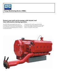
Pump Monitoring Device (PMD)................................................. 34<br />
Well Service Pumps (Extended Duty)....................................31 33<br />
Well Service Pumps (Intermittent Duty)................................23 31<br />
Safety Products<br />
Flow Line Safety Restraint System................................................19<br />
®<br />
Safety Iron .........................................................................15 16<br />
®<br />
Safety Iron Manifold Trailers ..................................................... 17<br />
Safety Hammer........................................................................18<br />
Worldwide Services<br />
Fluid End Repair ........................................................................ 37<br />
Iron Recertification & Refurbishment.......................................... 38<br />
Plunger Repair............................................................................ 37<br />
Pump Repair ..............................................................................37<br />
Rental Packages .........................................................................36<br />
Mobile Recertification Unit..........................................................39<br />
3
<strong>Weir</strong> <strong>SPM</strong><br />
Flow Control Reference Guide<br />
The following recommendations for <strong>Weir</strong> <strong>SPM</strong> flow control products are intended to be a<br />
guide to maximize efficiency, extended product life, and create a safer work environment.<br />
• Treating or discharge iron is produced for the<br />
following services:<br />
¤ Standard Service<br />
¤ H2S / Sour <strong>Gas</strong> Service<br />
¤ Low Temp Service<br />
• <strong>Weir</strong> <strong>SPM</strong> recommends that you designate specific<br />
strings of iron for the following applications, and<br />
that the designated iron remain in that service<br />
application throughout the product’s life:<br />
¤ Energized Fluids<br />
¤ Acids<br />
¤ Sour <strong>Gas</strong><br />
¤ Low Temperature Applications<br />
• Flow rates above 42 feet per second are not<br />
recommended.<br />
• Every string of iron should be pressurized to its<br />
maximum planned working pressure prior to each<br />
use.<br />
• Pressure seal line pipe threads are not<br />
recommended for pulsating service above 10,000<br />
psi or where side loading or erosion are suspected.<br />
(Integral or Non-Pressure seal threads are<br />
recommended.)<br />
• Most flow control products are certified for the<br />
following temperature rating:<br />
¤ Minimum: -30° C<br />
¤ Maximum: 110° C<br />
• Personnel must not be around pressure vessel products<br />
while pressure is present or being applied.<br />
• Each string, as well as each component, must have<br />
regular intervals of maintenance and inspection for safe,<br />
proper performance.<br />
• Never tighten or hammer wing unions when pressure is<br />
apparent.<br />
• Welding, brazing or heating on high pressure <strong>Weir</strong> <strong>SPM</strong><br />
components is prohibited.<br />
• <strong>General</strong> maintenance will extend the life of flow control<br />
products.<br />
¤ Grease plug valves and swivel joints after every<br />
job.<br />
¤ Replace seals to help prevent leaks and washouts<br />
of seal faces.<br />
¤ Clean all seal areas thoroughly.<br />
¤ Flush all products with water after each job.<br />
®<br />
Hammer Union & Safety Iron Connections<br />
Broadening the product line to meet the needs of our customers and the industry as a whole, <strong>Weir</strong> <strong>SPM</strong> currently<br />
offers flow control products in two styles of end connections. Traditional hammer union connections have long been<br />
the industry standard for connecting flow line components. Consisting of a wing nut and sub, and threaded end,<br />
®<br />
hammer union connections require the use of a sledgehammer to assemble. <strong>Weir</strong> <strong>SPM</strong>’s patented Safety Iron was<br />
designed to offer a safer and more effective alternative to the hammer union connection. Consisting of a seal ring,<br />
®<br />
upper clamp utilizing “captive bolts”, and lower threaded clamp, Safety Iron is assembled with the use of an impact<br />
®<br />
wrench instead of a sledgehammer. Both hammer unions and Safety Iron connections offered by <strong>Weir</strong> <strong>SPM</strong> are<br />
manufactured under strict quality standards and have proven to perform consistently in the field. For information on<br />
®<br />
Safety Iron , please see page 15 and 16.<br />
Most flow control products manufactured by <strong>Weir</strong> <strong>SPM</strong> can be made with either<br />
®<br />
Safety Iron or Hammer Union connections.<br />
4
<strong>Weir</strong> <strong>SPM</strong><br />
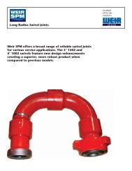
Swivel Joints<br />
<strong>Weir</strong> <strong>SPM</strong>’s 3” Fig. 1502 and 4” Fig. 1002 Long Radius Swivel Joints have undergone a design enhancement,<br />
creating a superior and longer lasting product. New features have created a swivel with extended life while<br />
maintaining uniform flow.<br />
New features include:<br />
• Additional erosion material under critical ball<br />
race locations:<br />
¤ 3” Fig. 1502 - over 13% more<br />
¤ 4” Fig. 1002 - over 22% more<br />
• More stable assembly with better load distribution<br />
in 3” Fig. 1502 series, featuring longer ball race life.<br />
• Better distribution of material for more robust female<br />
ball race components in 3” Fig. 1502 and 4” Fig.<br />
1002 models.<br />
• No danger for any mismatches.<br />
• Available in traditional hammer union styles or in <strong>Weir</strong><br />
®<br />
<strong>SPM</strong>’s patented Safety Iron connections.<br />
All <strong>Weir</strong> <strong>SPM</strong> swivel joints feature uniform wall thickness<br />
throughout for longer and more uniform flow of fluids<br />
(including slurries and abrasives), elastomeric packing<br />
for service to 225°F, instream packing that is designed<br />
not to enter stream regardless of velocity, and improved<br />
lubrication.<br />
Style 10 MxF Style 10 MxM Style 20<br />
FxM<br />
Style 30 FxM<br />
Style 80 MxF<br />
Style 50 MxF<br />
Style 100<br />
FxM<br />
Style 50 FxF<br />
Style 60<br />
MxM<br />
Style 100<br />
MxM<br />
Pressure<br />
Rating<br />
Style 10 Fig. 1502 MxF<br />
Style 10 Fig. 1502 MxM<br />
Style 20 Fig. 1502 MxF<br />
Style 30 Fig. 1502 MxF<br />
Style 50 Fig. 1502 MxF<br />
Style 60 Fig. 1502 MxF<br />
Style 80 Fig. 1502 MxF<br />
Style 10 Fig. 602 MxF<br />
Style 10 Fig. 602 MxM<br />
Style 50 Fig. 602 MxF<br />
Style 100 Fig. 1502 MxF<br />
Style 100 Fig. 1502 MxM<br />
Style 10 Fig. 1002 MxF<br />
Style 10 Fig. 1002 MxM<br />
Style 50 Fig. 1002 MxF<br />
Style 10 Threaded Swivel<br />
Style 20 Threaded Swivel<br />
Style 50 Threaded Swivel<br />
Size<br />
2”<br />
2” H2S<br />
3”<br />
•<br />
• •<br />
•<br />
3”<br />
H2S<br />
3” x<br />
2”<br />
• • • • • •<br />
•<br />
• • • • •<br />
• • • • •<br />
4”<br />
• • • •<br />
• •<br />
• •<br />
• • •<br />
• • •<br />
• • • •<br />
•<br />
•<br />
•<br />
<strong>Weir</strong> <strong>SPM</strong>'s product mix is constantly being revised to meet customer needs. Contact<br />
<strong>Weir</strong> <strong>SPM</strong> Engineering for the latest product offering information.<br />
•<br />
•<br />
•<br />
•<br />
•<br />
•<br />
•<br />
5
<strong>Weir</strong> <strong>SPM</strong><br />
Steel Hose Loops and Pipe<br />
Steel Hose Loops<br />
<strong>Weir</strong> <strong>SPM</strong> all-steel hose loops are used for a variety of<br />
high pressure well service applications including<br />
discharge lines, water lines, cementing and circulating<br />
lines, well test lines and temporary flow lines.<br />
<strong>Weir</strong> <strong>SPM</strong> all-steel hoses utilize field-proven <strong>Weir</strong> <strong>SPM</strong><br />
swivel joints for greater flexibility, shock and vibration<br />
resistance, and more uniform flow. Also<br />
utilized are <strong>Weir</strong> <strong>SPM</strong> wing union end<br />
connections for fast, pressure-tight<br />
make-up and break-out.<br />
These rugged hoses handle a full range of<br />
fluids to cold working pressures up to 15,000<br />
psi and come in sizes and configurations to<br />
meet any need. Hoses for sour gas service are<br />
available at cold working pressure up to<br />
10,000 psi. <strong>Weir</strong> <strong>SPM</strong> hoses are designed to<br />
easily and conveniently fold up for storage<br />
and transportation.<br />
Flow Line Piping<br />
<strong>Weir</strong> <strong>SPM</strong><br />
Model<br />
Long<br />
Radius<br />
Swivel<br />
Joints<br />
Long<br />
Radius<br />
Swivel<br />
Joints<br />
<strong>Weir</strong> <strong>SPM</strong> all-steel, one piece flow line piping, with wing<br />
union end connections, eliminates the need for welds or<br />
threads for an uninterrupted bore and greater flow. This<br />
light-weight piping is available in lengths to 10 feet to<br />
handle fluids at cold working pressures to 15,000 psi.<br />
They are used on high-pressure<br />
discharge lines, auxiliary flow<br />
lines, choke-and-kill lines and<br />
for abrasive applications.<br />
<strong>Weir</strong> <strong>SPM</strong> also manufactures<br />
flow line piping in nonpressure<br />
seal thread<br />
styles as well as butt<br />
weld styles in sizes<br />
ranging from 1" to 4”<br />
and in pressure ranges from<br />
6,000 to 20,000 psi, up to 20<br />
feet in length.<br />
Color<br />
Code<br />
Olive<br />
†<br />
Green<br />
Red<br />
† Sour <strong>Gas</strong> Service<br />
<strong>Weir</strong> <strong>SPM</strong> is in the process of<br />
adding an identification groove to all<br />
NPST subs. This is being implemented<br />
per the Shell mandate.<br />
Black •<br />
Size<br />
(In.)<br />
2<br />
2<br />
3<br />
3<br />
4<br />
Method of Construction<br />
Threaded NPS Integral Welded<br />
Integral Style<br />
•<br />
•<br />
Type of<br />
Service<br />
Standard<br />
Sour <strong>Gas</strong><br />
Standard<br />
Sour <strong>Gas</strong><br />
Standard<br />
•<br />
•<br />
NPS & Butt Weld Piping<br />
Style<br />
Fig. 602<br />
Fig. 1002<br />
Fig. 1502<br />
Fig. 1502<br />
Fig. 2002<br />
Fig. 2202<br />
†<br />
†<br />
NSCWP*<br />
(PSI)<br />
6,000<br />
10,000<br />
10,000<br />
15,000<br />
20,000<br />
15,000<br />
•<br />
•<br />
NSCWP*<br />
(PSI)<br />
15,000<br />
10,000<br />
15,000<br />
10,000<br />
15,000<br />
NSCWP*<br />
(PSI)<br />
10,000<br />
15,000<br />
10,000<br />
1” 1½” 2” 3” 4”<br />
•<br />
•<br />
•<br />
•<br />
*Non-Shock Cold Working Pressure<br />
†<br />
Sour <strong>Gas</strong> Service<br />
•<br />
•<br />
•<br />
•<br />
Size (In.)<br />
2 3<br />
•<br />
•<br />
•<br />
End<br />
Connection<br />
•<br />
•<br />
*Non-Shock Cold Working Pressure<br />
•<br />
•<br />
•<br />
•<br />
•<br />
•<br />
•<br />
•<br />
Fig. 1502 Union<br />
Fig. 1502 Union<br />
Fig. 1502 Union<br />
Fig. 1502 Union<br />
Fig. 1502 Union<br />
•<br />
•<br />
•<br />
Non<br />
Press<br />
Seal<br />
•<br />
•<br />
•<br />
Butt<br />
Weld<br />
<strong>Weir</strong> <strong>SPM</strong>'s product mix is constantly being revised to meet customer needs. Contact<br />
<strong>Weir</strong> <strong>SPM</strong> Engineering for the latest product offering information.<br />
•<br />
•<br />
•<br />
•<br />
•<br />
•<br />
•<br />
•<br />
6
<strong>Weir</strong> <strong>SPM</strong><br />
Plug Valves<br />
1", 1" X 2", 1½", and 2" Plug Valves<br />
<strong>Weir</strong> <strong>SPM</strong> high pressure plug valves are tough, fieldproven<br />
units that provide dependable service for<br />
applications such as cementing, fracturing, acidizing,<br />
coiled tubing, and sand control. Available in 1", 1" X 2",<br />
1½” and 2" sizes and in pressure ratings to 15,000 psi<br />
NSCWP*, <strong>Weir</strong> <strong>SPM</strong> plug valves feature quality<br />
components throughout for greater dependability,<br />
minimum weight, and maximum strength. Plug valves are<br />
available in standard service and sour gas service models.<br />
Special models are available to 20,000 psi.<br />
3" and 4" Plug Valves<br />
<strong>Weir</strong> <strong>SPM</strong> three-inch and four-inch plug valves are<br />
available in pressure ratings to 20,000 psi NSCWP*.<br />
Features include a flanged body for easier maintenance,<br />
integral inlets and outlets, hand crank, locked-open and<br />
shut gear drive standard, and multiple lubricating inlets.<br />
Standard service and sour gas service models are available.<br />
<strong>Weir</strong> <strong>SPM</strong>'s latest plug valve offering is the 3" SP150<br />
Manual Actuated Plug Valve.<br />
Remote Operation<br />
Hydraulic and pneumatic<br />
actuators are available<br />
for all sizes of plug<br />
valves, which enhances<br />
safety in the field.<br />
2” PLUG<br />
VALVE<br />
Valve<br />
Model<br />
SP50TF<br />
SP100TF<br />
SP150TF<br />
SP150TM<br />
SP150TMF<br />
SP150WU<br />
SP200WU<br />
NSCWP* End<br />
(PSI) Connections 1”<br />
5,000<br />
10,000<br />
15,000<br />
15,000<br />
15,000<br />
15,000<br />
20,000<br />
Special models are availale in 20,000 psi.<br />
Threaded<br />
Threaded<br />
Threaded<br />
Threaded<br />
Threaded<br />
Fig. 1502<br />
Fig. 2002<br />
•<br />
•<br />
*Non-Shock Cold Working Pressure<br />
1” X 2”<br />
•<br />
•<br />
•<br />
Repair and Seal Kits<br />
<strong>Weir</strong> <strong>SPM</strong> repair kits and seal kits contain all the parts<br />
necessary to rebuild valves in the field or in the shop.<br />
<strong>Weir</strong> <strong>SPM</strong> seal kits contain all items in the standard<br />
repair kit, except the plug. Individual components<br />
and elastomer kits are also available.<br />
4” PLUG<br />
VALVE<br />
Size<br />
1½” 2” 3” 4”<br />
•<br />
•<br />
•<br />
•<br />
• • • •<br />
• •<br />
<strong>Weir</strong> <strong>SPM</strong>'s product mix is constantly being revised to meet customer needs. Contact<br />
<strong>Weir</strong> <strong>SPM</strong> Engineering for the latest product offering information.<br />
7
<strong>Weir</strong> <strong>SPM</strong><br />
Check Valves<br />
<strong>Weir</strong> <strong>SPM</strong> check valves are made of high strength steel and are<br />
precision manufactured to exact tolerances for clapper styles<br />
in 2" through 4" sizes, dart styles in 1" through 3" sizes,<br />
and CO2/nitrogen styles in 2" and 3" sizes. The<br />
clapper design features either a standard coating or<br />
superior abrasion and acid resistant coating to give<br />
longer operating life in corrosive applications.<br />
The rugged valves operate at working pressures from<br />
6,000 to 20,000 psi in well service applications such as<br />
acidizing, cementing, fracturing, and energized fluids. <strong>Weir</strong> <strong>SPM</strong>'s<br />
check valves are manufactured from solid forgings to maximize<br />
strength and increase abrasion resistance.<br />
<strong>Weir</strong> <strong>SPM</strong> carries the most complete line of check valves available to the<br />
well service industry. Various configurations are offered, including<br />
wing-ahead (standard flow) or thread-ahead (reverse flow) models.<br />
CLAPPER STYLE<br />
Valve<br />
Size<br />
2” 1502<br />
2” 1502<br />
2” 2002<br />
3” 1502<br />
3” 1502<br />
3” 1502 Sour <strong>Gas</strong><br />
3” 1502 Sour <strong>Gas</strong><br />
3” 2002<br />
4” 602<br />
4” 1002<br />
4” 1002<br />
4” 1502<br />
4” 1502<br />
Available in Standard Flow (Wing Ahead)<br />
and Reverse Flow (Thread Ahead)<br />
*Non-Shock Cold Working Pressure<br />
Inlet<br />
Male<br />
Female<br />
Female<br />
Male<br />
Female<br />
Male<br />
Female<br />
Female<br />
Female<br />
Female<br />
Male<br />
Male<br />
Female<br />
Outlet<br />
Female<br />
Male<br />
Male<br />
Female<br />
Male<br />
Female<br />
Male<br />
Male<br />
Male<br />
Male<br />
Female<br />
Female<br />
Male<br />
Upstream /<br />
Downstream<br />
Reverse Flow<br />
Standard Flow<br />
Standard Flow<br />
Reverse Flow<br />
Standard Flow<br />
Reverse Flow<br />
Standard Flow<br />
Standard Flow<br />
Standard Flow<br />
Standard Flow<br />
Reverse Flow<br />
Reverse Flow<br />
Standard Flow<br />
NSCWP*<br />
(PSI)<br />
15,000<br />
15,000<br />
20,000<br />
15,000<br />
15,000<br />
10,000<br />
10,000<br />
20,000<br />
6,000<br />
10,000<br />
10,000<br />
15,000<br />
15,000<br />
<strong>Weir</strong> <strong>SPM</strong>'s product mix is constantly being revised to meet customer needs.<br />
Contact <strong>Weir</strong> <strong>SPM</strong> Engineering for the latest product offering information.<br />
<strong>Weir</strong> <strong>SPM</strong>'s Clapper Style<br />
Check Valves are placed in the<br />
treating line to allow flow to<br />
the well but isolate any back<br />
flow upstream of the valve.<br />
Clapper designs include Buna<br />
N rubber coatings for standard<br />
service, Viton for solvent and<br />
severe acid service, and<br />
Urethane coating for high<br />
abrasion resistance (HAR).<br />
8
<strong>Weir</strong> <strong>SPM</strong><br />
Check Valves<br />
DART STYLE<br />
Available in Standard Flow (Wing Ahead)<br />
and Reverse Flow (Thread Ahead)<br />
Valve<br />
Size<br />
1” 1502<br />
1” 1502<br />
1½” 1502<br />
1½” 1502<br />
2” 1502<br />
2” 1502<br />
3” 1502<br />
3” 1502<br />
2” 1502<br />
2” 1502<br />
3” 1502<br />
3” 1502<br />
Inlet<br />
Female<br />
Female<br />
Male<br />
Female<br />
Male<br />
Female<br />
Male<br />
Female<br />
Male<br />
Female<br />
Male<br />
Female<br />
*Non-Shock Cold Working Pressure<br />
CO2 / NITROGEN STYLE<br />
Valve<br />
Size<br />
2” 1502<br />
2” 1502<br />
3” 1502<br />
3” 1502<br />
Inlet<br />
Male<br />
Female<br />
Male<br />
Female<br />
*Non-Shock Cold Working Pressure<br />
Outlet<br />
Male<br />
Male<br />
Female<br />
Male<br />
Female<br />
Male<br />
Female<br />
Male<br />
Female<br />
Male<br />
Female<br />
Male<br />
Outlet<br />
Female<br />
Male<br />
Female<br />
Male<br />
Upstream /<br />
Downstream<br />
Reverse Flow<br />
Standard Flow<br />
Reverse Flow<br />
Standard Flow<br />
Reverse Flow<br />
Standard Flow<br />
Reverse Flow<br />
Standard Flow<br />
Reverse Flow H2S<br />
Standard Flow H2S<br />
Reverse Flow H2S<br />
Standard Flow H2S<br />
Upstream /<br />
Downstream<br />
Reverse Flow Low Temp<br />
Standard Flow Low Temp<br />
Reverse Flow Low Temp<br />
Standard Flow Low temp<br />
NSCWP*<br />
(PSI)<br />
15,000<br />
15,000<br />
15,000<br />
15,000<br />
15,000<br />
15,000<br />
15,000<br />
15,000<br />
10,000<br />
10,000<br />
10,000<br />
10,000<br />
NSCWP*<br />
(PSI)<br />
15,000<br />
15,000<br />
15,000<br />
15,000<br />
Service<br />
Standard<br />
Standard<br />
Standard<br />
Standard<br />
Standard<br />
Standard<br />
Standard<br />
Standard<br />
H2S<br />
H2S<br />
H2S<br />
H2S<br />
<strong>Weir</strong> <strong>SPM</strong>'s product mix is constantly being revised to meet customer needs. Contact<br />
<strong>Weir</strong> <strong>SPM</strong> Engineering for the latest product offering information.<br />
Available in Standard Flow (Wing Ahead)<br />
and Reverse Flow (Thread Ahead)<br />
Service<br />
Standard<br />
Standard<br />
Standard<br />
Standard<br />
<strong>Weir</strong> <strong>SPM</strong>'s product mix is constantly being revised to meet customer needs. Contact<br />
<strong>Weir</strong> <strong>SPM</strong> Engineering for the latest product offering information.<br />
The Dart Style Valve is<br />
constructed of a twopiece<br />
body that houses an<br />
inline spring loaded dart.<br />
When fluid enters from<br />
the inlet side, it will<br />
overcome the low spring<br />
force on the dart. The dart<br />
will travel away from the<br />
inlet and allow the fluid to<br />
flow around towards the<br />
outlet. When fluid flow<br />
stops, the light spring<br />
force closes the dart<br />
against its seat,<br />
preventing fluid from<br />
flowing back through the<br />
flow line. The <strong>Weir</strong> <strong>SPM</strong><br />
Dart Style Check Valve is<br />
available for standard<br />
service and for sour gas<br />
(H2S) environments.<br />
<strong>Weir</strong> <strong>SPM</strong> offers a specially<br />
designed CO2/Nitrogen<br />
Poppet Check Valve in<br />
sizes 2" and 3" to produce<br />
increased safety by<br />
preventing back flow in<br />
volatile CO2 and Nitrogen<br />
pumping flow lines.<br />
These stainless steel trim<br />
valves ensure that fluid<br />
cannot flow back into the<br />
manifold area or into<br />
pumps, and are rated at<br />
15,000 psi.<br />
9
<strong>Weir</strong> <strong>SPM</strong><br />
Relief Valves<br />
<strong>Weir</strong> <strong>SPM</strong> Emergency Relief Valves provide overpressure<br />
protection for reciprocating pumps,<br />
treating lines, pressure vessels and other equipment<br />
operating under a variety of pressure and flow<br />
conditions. The valves are compact, simple to<br />
operate and rely on the system's pressure to open<br />
when a preset pressure is exceeded, and<br />
automatically snap shut when the pressure drops.<br />
The valves are externally adjustable, and unlike<br />
shear relief valves, which use common nails to<br />
trigger the valve, <strong>Weir</strong> <strong>SPM</strong>’s Emergency Relief<br />
Valves utilize an internal spring, nitrogen, or rig air<br />
to activate opening and closing. Valves are available<br />
in 2", 3" and 4" models. Operating pressures range<br />
from 1,000 psi to 20,000 psi.<br />
Standard service and sour gas<br />
models are available.<br />
Size<br />
3” Nitrogen Actuated<br />
Relief Valve<br />
2”<br />
3”<br />
4”<br />
Description<br />
3” Spring Actuated<br />
Relief Valve<br />
1502 M Inlet, Line Pipe Thread Outlet<br />
1502 M Inlet, 1502 F Outlet<br />
1502 M Inlet, 1502 F Outlet Sour <strong>Gas</strong><br />
2002 M Inlet, 2002 F Outlet<br />
2202 M Inlet, 2202 F Outlet Sour <strong>Gas</strong><br />
602 M Inlet, 602 F Outlet<br />
1502 M Inlet, 1502 F Outlet<br />
602 M Inlet, 602 F Outlet<br />
1002 M Inlet, 1002 F Outlet<br />
1502 M Inlet, 1502 F Outlet<br />
Spring<br />
Design Style<br />
•<br />
•<br />
•<br />
•<br />
•<br />
•<br />
•<br />
Note:<br />
Approximate flow rate for relief valves:<br />
• 2” Spring - 150 GPM Max.<br />
• 3” Spring - 430 GPM Max.<br />
• 3” and 4” Back Pressure ERV - 750 GPM Max.<br />
• 3” and 4” Unloading Valve - 1000 GPM Max.<br />
As flow requirements increase, then multiple valves may<br />
be preferred, and are permissible. You may find that two<br />
of the 2” valves are a better economic combination than<br />
one 3” valve. Multiples of either valve are allowed as<br />
long as the valves are all set within 10% of each other.<br />
Example: If a customer requires a flow of 400 GPM, he<br />
may choose to use three 2” spring operated valves or<br />
one 3” spring operated valve.<br />
Nitrogen<br />
Actuated<br />
<strong>Weir</strong> <strong>SPM</strong>'s product mix is constantly being revised to meet customer needs. Contact <strong>Weir</strong> <strong>SPM</strong><br />
Engineering for the latest product offering information.<br />
•<br />
•<br />
•<br />
•<br />
•<br />
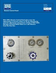
The Remote Control Panel is a simple and accurate tool to<br />
adjust the settings of the Nitrogen Actuated Relief Valves from<br />
a safe distance during operation.<br />
For more information, see page 35.<br />
10
<strong>Weir</strong> <strong>SPM</strong><br />
Hammer Unions<br />
<strong>Weir</strong> <strong>SPM</strong> hammer unions are available in a wide range of sizes and in working pressures to 20,000 psi. Pressure<br />
seal, non-pressure seal, and welded styles are offered in various sizes and pressures. All <strong>Weir</strong> <strong>SPM</strong> hammer unions<br />
provide pressure-tight, positive sealing and are available for standard service and sour gas models. <strong>Weir</strong> <strong>SPM</strong><br />
hammer unions for sour gas service are specially heat-treated for controlled hardness and utilize fluorocarbon<br />
elastomer seal rings.<br />
Figure<br />
Number<br />
100<br />
200<br />
206<br />
207<br />
400<br />
402<br />
602<br />
1002<br />
1502<br />
2002<br />
2202<br />
*Non-Shock Cold Working Pressure<br />
Fig. 100<br />
Black Nut<br />
Yellow Subs<br />
An economical union with<br />
precision machined metalto-metal<br />
sealing surfaces for<br />
air, water, oil or gas service<br />
to 1,000 psi NSCWP*.<br />
Fig. 402<br />
Black Nut<br />
Black Subs<br />
A resilient lip-type seal<br />
for air, water, oil or<br />
mud service to 4,000<br />
psi NSCWP*.<br />
*Non-Shock Cold<br />
Working Pressure<br />
Pressure<br />
Rating (NSCWP*)<br />
1,000<br />
2,000<br />
2,000<br />
2,000<br />
4,000<br />
4,000<br />
6,000<br />
10,000<br />
15,000<br />
20,000<br />
15,000<br />
1<br />
•<br />
•<br />
•<br />
•<br />
•<br />
Fig. 200 Fig. 206 Fig. 207 Fig. 400<br />
Blue Nut<br />
Gray Subs<br />
A precision metal-to-metal<br />
sealing surface between male<br />
and female subs for air, water,<br />
oil, gas and mud service to<br />
2,000 psi NSCWP*.<br />
Blue Nut<br />
Gray Subs<br />
A precision metal-to-metal seal<br />
plus O-ring seal for air, water,<br />
gas, oil, and mud service to<br />
2,000 psi NSCWP*.<br />
Blue Cap<br />
Gray Subs<br />
Interchangeable Fig. 206<br />
sub with blanking cap and<br />
O-ring seal to assure no-leak<br />
closure of manifolds and<br />
lines to 2,000 psi NSCWP*.<br />
Black Nut<br />
Red Subs<br />
Features a precision ball<br />
and cone sealing surface<br />
for sure metal-to-metal seal<br />
for air, water, oil, gas and<br />
mud service to 4,000 psi<br />
NSCWP*.<br />
Fig. 602 Fig. 1002 Fig. 1502 Fig. 2002 Fig. 2202<br />
Black Nut Red Nut Blue Nut White Nut Green Nut<br />
Orange Subs Blue Subs Red Subs White Subs Green Subs<br />
A replaceable lip-type<br />
seal ring minimizes<br />
fluid flow turbulence<br />
and gives pressure seal<br />
for air, water, oil, gas<br />
and mud service to<br />
6,000 psi NSCWP*.<br />
A resilient lip-type seal<br />
protects ball and cone<br />
seal against abrasion in<br />
air, water, oil, gas and<br />
mud service to 10,000<br />
psi NSCWP*.<br />
Nominal Pipe Size (Inches)<br />
1½ 2 2½ 3 4 6 8 10<br />
• • •<br />
• • • •<br />
• • • •<br />
•<br />
•<br />
•<br />
•<br />
• • •<br />
• • •<br />
• •<br />
•<br />
•<br />
••<br />
•<br />
For manifold and truck<br />
mountings or<br />
installations<br />
encountering high<br />
pressures including air,<br />
water, oil, gas and<br />
mud service to 15,000<br />
psi NSCWP*.<br />
•<br />
•<br />
•<br />
• •<br />
•<br />
•<br />
•<br />
•<br />
•<br />
For cementing,<br />
fracturing, acidizing,<br />
testing and choke-andkill<br />
lines where<br />
extreme pressures are<br />
encountered to 20,000<br />
psi NSCWP*<br />
•<br />
• •<br />
<strong>Weir</strong> <strong>SPM</strong>'s product mix is constantly being revised to meet customer needs. Contact <strong>Weir</strong> <strong>SPM</strong> Engineering for the latest product offering information.<br />
Especially for sour gas<br />
service; with heattreated<br />
components,<br />
fluoroelastomer seal<br />
rings. For service to<br />
15,000 psi NSCWP*.<br />
11
<strong>Weir</strong> <strong>SPM</strong><br />
Integral Union Connections<br />
<strong>Weir</strong> <strong>SPM</strong> manufactures a quality line of high-pressure integral union connections in a broad range of configurations<br />
and sizes from 1" through 4" and in pressure ratings to 20,000 psi NSCWP*. Manufactured from high strength alloy<br />
steel forgings, <strong>Weir</strong> <strong>SPM</strong> integrals feature a lightweight design not found in competitors’ products. All <strong>Weir</strong> <strong>SPM</strong><br />
integral union connections are subjected to controlled heat-treat processes.<br />
Size<br />
1”<br />
1½”<br />
2”<br />
3”<br />
4”<br />
Fig. 1502<br />
Fig. 2202<br />
Fig. 602 Fig. 1002 Fig. 1502 10,000 psi* Fig. 2002 15,000 psi*<br />
6,000 psi* 10,000 psi* 15,000 psi* H2S 20,000 psi* H2S<br />
•<br />
• •<br />
*Non-Shock Cold Working Pressure<br />
*Non-Shock Cold Working Pressure<br />
•<br />
•<br />
•<br />
•<br />
•<br />
UNION CHANGEOVER AND CROSSOVER ADAPTORS<br />
UNION BULL, GAUGE AND LIFTING<br />
BULL PLUGS<br />
Available in 1", 1 1/2", 2", 3" and 4" sizes in male and<br />
female models. Available in pressure ratings to 20,000<br />
psi NSCWP* in standard service, and up to 15,000 psi<br />
in sour gas service. Also available with special<br />
ports for high pressure testing.<br />
•<br />
•<br />
•<br />
•<br />
•<br />
•<br />
•<br />
•<br />
•<br />
All Female<br />
(Thread)<br />
•<br />
•<br />
•<br />
•<br />
•<br />
All Male<br />
(Wing)<br />
•<br />
•<br />
•<br />
•<br />
•<br />
Combination<br />
Styles and<br />
Sizes<br />
<strong>Weir</strong> <strong>SPM</strong>'s product mix is constantly being revised to meet customer needs. Contact <strong>Weir</strong> <strong>SPM</strong> Engineering for the latest product offering information.<br />
Available in a variety of sizes and thread types in female-tomale,<br />
female-to-female, and male-to-male configurations<br />
from 1" thru 4", in pressure ratings from 6,000 to 20,000<br />
psi NSCWP* in standard service, and up to 15,000 psi<br />
in sour gas service.<br />
UNION MALE AND FEMALE TO PIPE, AND<br />
TUBING THREAD SWAGES<br />
•<br />
•<br />
•<br />
•<br />
•<br />
Available in numerous sizes and threaded configurations<br />
from 1" thru 4" in pressure ratings from 6,000 to 10,000<br />
psi NSCWP*.<br />
12
<strong>Weir</strong> <strong>SPM</strong><br />
Manifolds, Frac Heads and Cement Heads<br />
PUMP DISCHARGE, FLOW-THRU, TEST AND CIRCULATION<br />
MANIFOLDS<br />
®<br />
Pump discharge manifolds are available in Safety Iron<br />
single or multiple discharge outlets in a Pump<br />
variety of integral union connections up to Discharge<br />
20,000 psi NSCWP*. Features include full Manifold<br />
bore, thick-wall tubing and pump discharge<br />
flanges to fit most major brands of pumps.<br />
Flow-thru, test, and circulation manifolds<br />
are available in both 5,000 and 10,000 psi<br />
NSCWP* for threaded, and to 20,000 psi NSCWP* for<br />
all-integral connection sizes. All styles utilize proven <strong>Weir</strong><br />
<strong>SPM</strong> plug valves of all sizes, 1" through 4”. Available<br />
variations include fixed choke and adjustable choke<br />
models.<br />
®<br />
<strong>Weir</strong> <strong>SPM</strong>'s Safety Iron has proven to be an ideal choice<br />
for semi-permanent applications. Flow-thru manifolds and<br />
pump bridles are just two of the applications when Safety<br />
®<br />
Iron has performed exceptionally in the field.<br />
*Non-Shock Cold Working Pressure<br />
CEMENT HEADS FRAC HEADS<br />
Utilizing superior field-tested welding techniques, <strong>Weir</strong><br />
<strong>SPM</strong> cement heads provide high-pressure performance<br />
in a variety of designs to meet the needs of the industry.<br />
Featuring single or double plug head designs,<br />
easy-to-attach landing joints, and reliable plug pin<br />
performance, <strong>Weir</strong> <strong>SPM</strong> cement heads perform with<br />
consistency and reliability in the field.<br />
Single and Double<br />
Head designs are<br />
available in the<br />
following sizes:<br />
2.875”<br />
3.50”<br />
4.50”<br />
5.0” - 5.5”<br />
7.0” - 7.63”<br />
8.63” - 9.63”<br />
10.75” - 11.75”<br />
13.375”<br />
16.0”<br />
18.63” - 20.0”<br />
Cement Head Manifolds<br />
also available.<br />
Flow-Thru<br />
Manifold<br />
<strong>Weir</strong> <strong>SPM</strong>’s customizable frac heads allow customers<br />
to design their ideal frac head for reliable and<br />
consistent performance on their frac sites.<br />
<strong>Weir</strong> <strong>SPM</strong> frac heads are manufactured from<br />
hardened steel and feature field-proven durable<br />
welds at the branches. Available in two styles, the<br />
"Goat Head" Style and "Inlet" Style, <strong>Weir</strong> <strong>SPM</strong><br />
customizes frac head orders to customer<br />
specifications through the use of a Frac Head Request<br />
Form.<br />
Through the utilization of the Frac Head Request Form,<br />
customers may customize their purchase through the<br />
following design options:<br />
• Pressure Rating<br />
• Top Connection Type<br />
• Minimum Through-Bore<br />
Width<br />
• Number of Side Connections<br />
• Side Connection Branch Angle<br />
• Side Connection Branch, Type,<br />
and Pressure Rating<br />
• Bottom Connection Type<br />
13
<strong>Weir</strong> <strong>SPM</strong><br />
Misc. Flow Control Products<br />
Choke Tees<br />
Adjustable and positive choke tees are primarily used in choke manifolds, flow thru manifolds and test<br />
manifolds. Various forged-body configurations are available in 2-inch and 3-inch sizes, each rated at<br />
15,000 psi NSCWP*. Choke tees are also available in sour gas configuration.<br />
*Non-Shock Cold Working Pressure<br />
Butterfly Valves<br />
Available in Sizes<br />
<strong>Weir</strong> <strong>SPM</strong> butterfly valve's specially designed Ranging from 3 Inches<br />
disc allows for a noticeably smoother media<br />
to 12 Inches.<br />
flow, reducing or eliminating turbulence<br />
commonly found in other valves. Another superior<br />
design feature is the split stem, which allows the disc to automatically<br />
center in the media flow path, thus assuring an even seal around the disc.<br />
A one-piece phenolic back-up ring allows internal pressure to anchor the seat<br />
within the valve body and prevents seat walking. Various seat and disk materials<br />
are available.<br />
®<br />
Sur-Drop Ball Injectors No-Go Gauge Kits<br />
®<br />
<strong>Weir</strong> <strong>SPM</strong>'s Sur-Drop High-Pressure Ball Injector features<br />
the “Positive Feed System", resulting in a reliable feed and<br />
injection rate. New design revisions have enhanced<br />
operating performance, made maintenance more<br />
convenient, and greatly reduced lead time for faster<br />
response to customer needs.<br />
New Design Upgrades:<br />
• Improved manufacturing processes<br />
allow for more precise machined parts.<br />
• Increased flexibility in operation by<br />
consolidating ball cartridge sizes.<br />
« 5/8" & 3/4"<br />
« 7/8" & 1"<br />
« 1-1/8" & 1-1/4"<br />
• Increased convenience in maintenance.<br />
« Two-piece screw assembly<br />
allows for more convenient<br />
replacement of drive stem,<br />
without replacing entire<br />
assembly.<br />
• Easy manual loading eliminates<br />
use of awkward tools.<br />
During extended service of flow control products in<br />
the field, components will naturally begin to show<br />
symptoms of wear.<br />
In order to allow<br />
convenient<br />
inspection of<br />
these components,<br />
<strong>Weir</strong> <strong>SPM</strong> now offers<br />
No-Go Gauge Kits.<br />
These gauges<br />
allow for easy<br />
qualification of<br />
worn hammer<br />
union assemblies,<br />
swivel ball races,<br />
and sub<br />
connections.<br />
Available in 1 1/2", 2",<br />
3" and 4"<br />
By inserting the gauge into the worn feature of the<br />
component, the part can be easily deemed<br />
acceptable or unacceptable. Each <strong>Weir</strong> <strong>SPM</strong> gauge is<br />
machined from hardened tool steel and is chrome<br />
plated for exceptional long life.<br />
14
<strong>Weir</strong> <strong>SPM</strong><br />
®<br />
Safety Iron<br />
®<br />
Safety Iron is a clamp connecting flow line system developed to replace<br />
traditional wing nut union connections. The product consists of a seal<br />
ring utilizing a soft seal and a metal-to-metal seal, an upper clamp with<br />
"captive" bolts, and a lower threaded clamp. The metal seal ring and<br />
rubber seal freely slip into the tapered flange end. Sealing is<br />
accomplished by the end crush on the rubber seal and tapered metal<br />
contact from the clamp force. The result is a superior performing<br />
connection compared to traditional hammer union connections, and a<br />
safer work environment by allowing the user to "throw away the<br />
hammer."<br />
Available in 1½” through 4”<br />
in pressure ratings up to 20,000 psi.<br />
U.S. Patent No. 7,204,525<br />
®<br />
Benefits of Safety Iron vs. Traditional Hammer Union Connections<br />
• Greater Safety<br />
• Less Physically Demanding Assembly/Disassembly<br />
• Less Injury Prone<br />
• Less Labor Intensive & Less Expensive Reinspection<br />
• Faster Break-down<br />
• More Reliable Seal<br />
®<br />
Safety Iron Product Line:<br />
• Swivel Joints<br />
• Check Valves<br />
• Plug Valves<br />
• Relief Valves<br />
• Integrals (Tees, Wyes, Elles, Crosses, and Crossovers)<br />
• Pipe<br />
• Pump Discharge Manifolds<br />
<strong>Weir</strong> <strong>SPM</strong> offers Safety Iron Kits in 1 1/2" 15K, 2"<br />
15K, 2" 20K, 3" 15K, 3" 20K, 4" 10K, and 4" 15K.<br />
Kits Include:<br />
1. (2) Impact Wrenches - 3/4" Drive w/ 3/8" Plug<br />
2. (2) Torque Stick - 3/4" Drive<br />
3. (2) Hex Socket - 3/4" Drive<br />
4. (1) Hose Assembly - 50' x 3/4" Hose w/<br />
Crowsfoot Connection<br />
5. (2) Hose Assembly - 50' x 1/2" Hose w/<br />
Crowsfoot and 3/8" Coupler Connection<br />
6. (1) Wye - 3/4" Crowsfoot<br />
7. (7) Crowsfoot Washer Seal<br />
8. (8) Crowsfoot Pin<br />
® MINIMUM AIR REQUIREMENTS<br />
3 2<br />
*The kits allow the use of two impact<br />
wrenches from one air supply source.<br />
1<br />
• 45 SCFM PER IMPACT WRENCH<br />
• 80 PSI AT IMPACT WRENCH<br />
5<br />
6<br />
AIR SUPPLY<br />
4<br />
15
<strong>Weir</strong> <strong>SPM</strong><br />
®<br />
Safety Iron<br />
®<br />
Safety Iron Connection<br />
®<br />
Safety Iron connections have a greater surface<br />
contact area for a much more stable connection<br />
®<br />
compared to hammer union seals. Safety Iron<br />
flanges are also more robust with larger sweeping<br />
radii for additional strength and vibration<br />
resistance.<br />
Contact Surfaces<br />
®<br />
Fire Safe Safety Iron<br />
Long sweeping radii<br />
for increased stability<br />
<strong>Weir</strong> <strong>SPM</strong>'s newest addition to its groundbreaking<br />
® ®<br />
Safety Iron product line is Fire Safe Safety Iron . Fire<br />
®<br />
Safe Safety Iron is designed to reduce many dangers<br />
associated with assembly of traditional flow lines on<br />
offshore rigs, while meeting API 6FB compliance for a<br />
safer working environment.<br />
®<br />
Fire Safe Safety Iron utilizes a metal-to-metal seal,<br />
consisting of a metal seal ring, an upper clamp<br />
featuring "captive bolts", and a lower threaded clamp.<br />
The system provides an effective seal while minimizing<br />
the necessary number of components needed to<br />
complete a flow line. There is no other offshore<br />
clamp-connecting flow line product on the market<br />
that utilizes less component parts than Fire Safe Safety<br />
®<br />
Iron .<br />
Traditional Hammer Union Connection<br />
Hammer union connections are limited to only one<br />
contact seal surface, greatly reducing the integrity<br />
of the connection. Hammer unions, with their<br />
thinner wall section at vital points and higher stress<br />
areas due to the jagged grooves of the threads,<br />
are more susceptible to damage as a result of<br />
vibration or side loading.<br />
Contact<br />
Surfaces<br />
Benefits:<br />
High Stress Areas<br />
• Removes the sledgehammer from the assembly<br />
of iron, increasing safety during offshore<br />
operations.<br />
• Designed to replace other existing clamp style<br />
connections with a reliable, easier to assemble<br />
connection.<br />
• Produces a reliable seal that will maintain<br />
integrity in the instance of fire.<br />
• For use in permanent or semi-permanent<br />
installation.<br />
• Metal-to-metal seal meets API 6FB compliance.<br />
• Available in 2" - 4", rated up to 10,000 psi.<br />
16
<strong>Weir</strong> <strong>SPM</strong><br />
®<br />
Safety Iron Manifold Trailers<br />
®<br />
<strong>Weir</strong> <strong>SPM</strong>'s Safety Iron Manifold Trailer provides the market<br />
with a uniquely designed manifold system that is ideally<br />
suited for stimulation operations, where vibration and side<br />
load have proven to be detrimental to the existing hammer<br />
union trailer models currently on the market.<br />
Product Features:<br />
• Multiple configurations allow for increased<br />
variability in flow rate, and inlet/outlet<br />
configuration.<br />
• Greater vibration resistance compared to<br />
traditional hammer union alternatives.<br />
• Large sweeping radii in high pressure<br />
components for increased strength at<br />
connections.<br />
• More robust wall thickness to prevent failure<br />
in high risk areas.<br />
• Available built-in coiled-cable suspension for<br />
high pressure component mounting increases<br />
flexibility and reduces risk of cracked integrals.<br />
• Isolation valves available for flexibility in flow<br />
line communication and utilization.<br />
• Available with crossovers at high pressure<br />
outlets for greater compatibility with existing<br />
inventories.<br />
• DOT certified trailer.<br />
Optional Design Configurations:<br />
®<br />
<strong>Weir</strong> <strong>SPM</strong> Safety Iron Manifold Trailers<br />
are available with flexible mounts, such<br />
as a coiled cable suspension mounting,<br />
for high pressure components, greatly<br />
reducing the chance of fatigue cracks in<br />
integral components due to the<br />
vibration caused during transport and<br />
operation.<br />
• Flexible high and low pressure line arrangements for<br />
various flow rates<br />
• Flexible high and low pressure inlet/outlet arrangements<br />
for various station configurations<br />
• High pressure iron size and pressure ratings<br />
(3" & 4" / 10K & 15K)<br />
• Isolation valves between the high and low pressure lines<br />
• Tee or lateral connections leading to swing arms<br />
• Configuration of swing arms<br />
17
<strong>Weir</strong> <strong>SPM</strong><br />
Safety Hammer<br />
<strong>Weir</strong> <strong>SPM</strong>'s newest product designed to increase<br />
safety on the work site is the Safety Hammer. The<br />
Safety Hammer promotes a safer work<br />
environment by reducing the dangers associated<br />
with assembling hammer union connections using a<br />
sledgehammer. Safety Hammer is a pneumatic<br />
tool designed to properly seal hammer union<br />
connections with the ease of pushing a button. The<br />
dangers of using a sledgehammer are greatly<br />
reduced as most connections on-site can be made<br />
with the Safety Hammer .<br />
The Safety Hammer is an assembly composed of<br />
two main parts: high strength alloy steel adaptor and<br />
pneumatic hammer. The steel adaptor can be<br />
changed out as needed to fit different union sizes. In<br />
order for the Safety Hammer to function as<br />
intended, <strong>Weir</strong> <strong>SPM</strong> recommends 29 SCFM per<br />
hammer, with an air pressure of 90 psi and 1/2" air<br />
supply hose size. The Safety Hammer will make up<br />
and break down the hammer union depending on its<br />
orientation.<br />
Available in 2" 1502, 3" 1502,<br />
4” 200/206 and 4" 602/1002.<br />
The Safety Hammer now features an upgraded impact tool made<br />
of a harder and tougher material for improved life with extended<br />
utility, and a redesigned contact end to minimize flaring of the edge.<br />
Pneumatic<br />
Device<br />
Hammer<br />
Tool<br />
Air<br />
Source<br />
Adaptor<br />
To use the Safety Hammer ,<br />
simply hand-tighten the<br />
hammer union connection until the wing nut ceases to<br />
rotate. Slide the Safety Hammer adapter over the wing nut<br />
so that it bears against one of the three lugs. Orient so that<br />
the impact tool striking the wing nut lug will tighten the<br />
connection. Apply a turning force to the gooseneck handle<br />
until the wing nut ceases to rotate. Squeeze the trigger and<br />
continue to apply a slight turning force to the gooseneck<br />
handle. The hammer union will be quickly tightened. There<br />
is no other tool on the market that allows for such convenient<br />
and safe assembly of hammer union connections.<br />
Benefits:<br />
• Lightweight design that is easy to install and operate.<br />
• Less labor intensive assembly/disassembly.<br />
• Lower risk of injury by removing hammer from<br />
assembly process.<br />
• Adaptor can easily be interchanged for different size<br />
wing unions.<br />
18
<strong>Weir</strong> <strong>SPM</strong><br />
Flow Line Safety Restraint System<br />
<strong>Weir</strong> <strong>SPM</strong>'s Flow Line Safety Restraint System is designed to help provide<br />
a safer environment in case of rupture or disengagement of the flow line<br />
while under pressure. The FSR has been credited with saving multiple lives<br />
and preventing catastrophic damage since its inception. FSR is<br />
recommended for all pumping service lines as they leave the skid or truck<br />
all the way to the wellhead, and should be mandatory for energized fluid<br />
pumping services. Systems are available for rent with <strong>Weir</strong> <strong>SPM</strong> representatives<br />
available to perform on-site training and full-service installation and support.<br />
The FSR system was acknowledged for its innovation and performance<br />
capabilities, receiving the Woelfel "Best Mechanical Engineering Innovation"<br />
Award from the American Society of Mechanical Engineering during the 2002<br />
Offshore Technology Conference. For peace of mind and increased safety on your<br />
site, there is no better option than the Flow Line Safety Restraint System.<br />
RENTAL PACKAGES<br />
<strong>Weir</strong> <strong>SPM</strong> has a large fleet<br />
of FSR Rental Units located<br />
around the globe for<br />
quick response to<br />
customer requests. Upon<br />
order, <strong>Weir</strong> <strong>SPM</strong><br />
technicians will deliver the<br />
unit to a site as requested<br />
and will provide training<br />
to customers' employees<br />
to ensure proper installation<br />
of components or provide<br />
full service installation. <strong>Weir</strong><br />
<strong>SPM</strong> offers FSR trailers, and<br />
customized cargo<br />
containers for offshore use, to better organize component<br />
parts and make transport of materials safer and more<br />
convenient. There is no more convenient way to satisfy the<br />
safety requirements of both the operator and service provider<br />
on site.<br />
The FSR Rental Fleet undergoes constant inspection, as well as<br />
regular recertification and testing to insure that the FSR<br />
components perform as expected. Each component features<br />
identification and recertification badges so the customer may<br />
verify the components comply with regulations.<br />
Spine<br />
It is critical that, since most <strong>Weir</strong> <strong>SPM</strong> products generate, control or direct pressurized fluids, those who work<br />
with these products be thoroughly trained in their proper application, safe handling, and installation. Misuse,<br />
side loading, improper maintenance, or disassembly under pressure can cause serious injury or death!<br />
Rib<br />
The Flow Line Safety Restraint<br />
System prevented this wellhead<br />
from becoming airborne and<br />
deterred the flow line from<br />
striking a functional gas well.<br />
Notice how the pipe is bent, yet<br />
still held in place.<br />
19
<strong>Weir</strong> <strong>SPM</strong><br />
Well Service Pumps<br />
<strong>Weir</strong> <strong>SPM</strong> manufactures the most comprehensive range of high-pressure plunger pumps in the industry. <strong>Weir</strong> <strong>SPM</strong>'s<br />
plunger pump designs incorporate the ultimate in weight and space savings while having a reputation for<br />
dependable service even in today's hybrid extended duty applications, such as under-balanced coiled tubing drilling.<br />
<strong>Weir</strong> <strong>SPM</strong> offers intermittent duty pump models for the full range of well service applications, and extended duty<br />
plunger pump models for those oilfield and industrial applications requiring greater work periods with a smallfootprint,<br />
lightweight pump.<br />
<strong>Weir</strong> <strong>SPM</strong>'s DNV Type Approved intermittent duty plunger pumps range from 250 BHP to 3500 BHP with pressure<br />
capabilities up to 20,000 psi. Premium plungers, valves, seats, packing, etc. can be configured to a variety of well<br />
service needs from mud based coiled tubing support services to hot oil, cementing, acidizing, fracturing, gravel<br />
packing, etc.<br />
<strong>Weir</strong> <strong>SPM</strong>'s durable extended duty plunger pumps range from 175 BHP to 1575 BHP. These extended duty plunger<br />
pumps are specially designed to provide durable service in extended applications one day and provide exceptional<br />
high pressure / high rate intermittent service the next. These pumps' unique versatility in duty cycle adaptability<br />
greatly increases the range of work that can be performed and the amount of revenue than can be generated with a<br />
single pump. These pumps are designed so that the expendable parts (packing, etc.) can easily be reconfigured for<br />
mud, water, drill cutting, acid, cement, etc.<br />
<strong>Weir</strong> <strong>SPM</strong> pumps are available with life cycle enhancing "auto-frettage" processing of the fluid cylinder. This very<br />
economical process adjusts for the harmful effects of cyclic stress and the stress corrosion cracking which can occur in<br />
high-pressure fluid cylinders. <strong>Weir</strong> <strong>SPM</strong>'s state-of-the-art auto-frettage process results in a fluid cylinder with several<br />
times the fatigue life expectancy at a fractional increase in cost.<br />
Classroom and shop training is available to better familiarize the customer with the design parameters, technical<br />
specifications and operating characteristics of each pump model.<br />
<strong>Weir</strong> <strong>SPM</strong> provides a wealth of technical data, assembly drawings and maintenance information on it's pumps (and<br />
flow control products as well) through an interactive home page on the Internet at www.weiroilandgas.com.<br />
Every <strong>Weir</strong> <strong>SPM</strong> pump is tested to full power in<br />
house before it is delivered to the customer to<br />
ensure quality and proper performance. <strong>Weir</strong><br />
<strong>SPM</strong>'s 4500 hp test booth can run any pump<br />
up to full working power before delivery to the<br />
end user.<br />
20
<strong>Weir</strong> <strong>SPM</strong><br />
Pump Reference Guide<br />
WEIR <strong>SPM</strong> PUMP MODEL EXPLANATION:<br />
1st letter indicates<br />
number of cylinders:<br />
T = triplex<br />
Q = quintuplex<br />
Common Pump Formulas:<br />
QWS - 2500 - SD<br />
2nd two letters indicate<br />
the intended duty cycle:<br />
WS = intermittent,<br />
such as well service<br />
HB = extended, such<br />
as hydroblast<br />
• Hydraulic Horse Power (HHP) = (GPM x PSI) / 1714<br />
• Brake Horse Power (BHP) = (GPM X PSI) / (1714 x ME)<br />
• Pressure (PSI) = (BHP x 1714 x ME) / GPM<br />
• GPM = (BHP x 1714 x ME) / PSI<br />
• Rod Load = PD x PD x .7854 x PSI<br />
• GPR = (PD x PD x .7854 x SL x NC) / 231<br />
• GPM = GPR x RPM<br />
Extending Pump Life & Preventative<br />
Maintenance Program<br />
Extending Pump Life:<br />
Extending pump life requires careful operation by the<br />
customer. The customer should observe and utilize the<br />
following tools and practices:<br />
• Dual inlet or Zoomie manifold<br />
• Properly sized and maintained suction pulsation<br />
dampeners<br />
• Properly maintained valves/seats/inserts<br />
• Improved discharge harmonics (may require high<br />
pressure dampener)<br />
• Correct piping placement, proper supercharging<br />
• Proper sand and gel concentrations and blender<br />
operations<br />
Numbers indicate<br />
max. rated BHP:<br />
2500 = 2500 BHP<br />
Last two letters indicate<br />
specialty designation:<br />
SD = super duty<br />
LW = special lightweight<br />
design<br />
S = short<br />
HV = horizontal valve<br />
DD = direct drive<br />
GPM - Gallons Per Minute<br />
PD - Plunger Diameter<br />
NC - Number of Cylinders<br />
ME - Mechanical Efficiency<br />
SL - Stroke Length<br />
GPR - Gallons Per Revolution<br />
Maintenance:<br />
At the very least, the following maintenance programs<br />
should be set up, operated, and recorded for review:<br />
• Power end lube oil and filter inspection<br />
• Fluid end valves and inserts inspection<br />
• Fluid end seats inspection<br />
• Fluid end valve springs inspection<br />
• Plunger packing inspection<br />
Proper maintenance practices are the best way to<br />
increase the life of your pumps and pump<br />
components. <strong>Weir</strong> <strong>SPM</strong> strongly suggests that each<br />
customer develop a maintenance program to be<br />
followed at all times.<br />
Pump Duty Cycles<br />
For information on pump duty cycles, Contact <strong>Weir</strong><br />
<strong>SPM</strong> Engineering.<br />
21
<strong>Weir</strong> <strong>SPM</strong><br />
Pump Reference Guide (Cont.)<br />
Autofrettage<br />
Intersecting bores in a fluid cylinder exhibit very high<br />
stresses at the corners of the intersection. To combat this<br />
problem created at the bore intersections, <strong>Weir</strong> <strong>SPM</strong><br />
recommends that the customer utilize the Autofrettage<br />
option when purchasing a fluid end. The Autofrettage<br />
procedure is a technique where a "one-time" high hydraulic<br />
pressure is imposed on the bore intersection of a new<br />
cylinder inducing plastic strain at the intersection while<br />
elastic strain remains elsewhere. Relaxation of this one time<br />
pressure treatment causes these high-risk areas to develop a<br />
residual compressive stress, mitigating the destructive<br />
effects of the fatigue. The Autofrettage process may not<br />
completely eliminate the likelihood of fatigue failure (since<br />
corrosion and erosion still occur). However, it should<br />
significantly increase the number of cycles the product can<br />
tolerate, ultimately extending the life of the fluid cylinder.<br />
Fluid End Configurations<br />
<strong>Weir</strong> <strong>SPM</strong> currently offers fluid ends in three configurations,<br />
OPI, "Wing" Style Suction Valve Stop, and Grooveless. The<br />
"Wing" style fluid end was an improvement over the<br />
industry standard OPI style for a number of reasons<br />
including cost, serviceability and fluid cylinder life. Due to<br />
the customer's need for increased pumping durations,<br />
rates, and pressures, <strong>Weir</strong> <strong>SPM</strong> has adopted a Groveless<br />
(GL) version of the suction valve stop. The GL design<br />
eliminates a groove in the fluid cylinder and is intended to<br />
extend the cylinder's life. All three versions are available<br />
and can be used throughout a broad range of the<br />
<strong>Weir</strong> <strong>SPM</strong> pump product line. Consult <strong>Weir</strong> <strong>SPM</strong> Sales to<br />
determine which style would be beneficial<br />
for you.<br />
The traditional "wing style" fluid end uses a grooved<br />
suction bore to lock the valve stop in place. This groove reduces<br />
material in key locations possibly leading to cracks in the<br />
cylinder during the mature phase of its life cycle.<br />
<strong>Weir</strong> <strong>SPM</strong>'s new Grooveless Fluid End eliminates the groove<br />
in the fluid cylinder by replacing the old “wing style” valve stop.<br />
The new valve stop design locks under a ridge in the fluid<br />
cylinder bore and is held in place through a stem on the<br />
suction cover.<br />
22
<strong>Weir</strong> <strong>SPM</strong><br />
TWS 600S<br />
TWS 600S Performance Data<br />
PLUNGER<br />
DIAMETER<br />
in<br />
(mm)<br />
2½<br />
(63.5)<br />
2¾<br />
(69.9)<br />
3<br />
(76.2)<br />
3½<br />
(88.9)<br />
4<br />
(101.6)<br />
4½<br />
(114.3)<br />
OUTPUT<br />
PER REV<br />
gal/rev<br />
(liter/rev)<br />
.38<br />
(1.4)<br />
.46<br />
(1.8)<br />
.55<br />
(2.1)<br />
.75<br />
(2.8)<br />
.98<br />
(3.7)<br />
1.24<br />
(4.7)<br />
gpm<br />
(lpm)<br />
19<br />
(72)<br />
23<br />
(87)<br />
28<br />
(104)<br />
37<br />
(142)<br />
49<br />
(185)<br />
62<br />
(235)<br />
DISPLACEMENT AT PUMP STROKES PER MINUTE / PINION RPM<br />
50 / 230<br />
psi<br />
(kg/cm²)<br />
20,372<br />
(1436)<br />
16,836<br />
(1186)<br />
14,147<br />
(997)<br />
10,394<br />
(732)<br />
7,958<br />
(561)<br />
6,288<br />
(443)<br />
120 / 552 200 / 920 300 / 1380 450 / 2070<br />
gpm<br />
(lpm)<br />
46<br />
(174)<br />
56<br />
(210)<br />
66<br />
(250)<br />
90<br />
(341)<br />
118<br />
(445)<br />
149<br />
(563)<br />
psi<br />
(kg/cm²)<br />
20,165<br />
(1421)<br />
16,665<br />
(1174)<br />
14,003<br />
INPUT POWER: BHP (Kw) 253 (188) 600 (448) 600 (448) 600 (448) 600 (448)<br />
(987)<br />
10,288<br />
(725)<br />
7,877<br />
(555)<br />
6,224<br />
(439)<br />
gpm<br />
(lpm)<br />
76<br />
(290)<br />
93<br />
(350)<br />
110<br />
(417)<br />
150<br />
(568)<br />
196<br />
(741)<br />
248<br />
(938)<br />
psi<br />
(kg/cm²) gpm<br />
(lpm)<br />
12,099<br />
(853)<br />
9,999<br />
(705)<br />
8,402<br />
(592)<br />
6,173<br />
(435)<br />
4,726<br />
(333)<br />
3,734<br />
(263)<br />
115<br />
(434)<br />
139<br />
(526)<br />
165<br />
(625)<br />
225<br />
(851)<br />
294<br />
(1112)<br />
372<br />
(1407)<br />
1 Based on 90% ME and 100% VE - Intermittent Service Only.<br />
2 For applications demanding pressures over 15,000 psi, contact <strong>Weir</strong> <strong>SPM</strong> Engineering.<br />
PRESSURE (PS )<br />
17000<br />
16000<br />
15000<br />
14000<br />
13000<br />
12000<br />
11000<br />
10000<br />
9000<br />
8000<br />
7000<br />
6000<br />
5000<br />
4000<br />
3000<br />
2000<br />
1000<br />
0<br />
1, 2<br />
The TWS 600S offers a versatile small footprint pump that can<br />
perform a variety of duties for the well service industry. The<br />
unique design features an offset crankshaft / crosshead design<br />
which substantially reduces the load on both the crosshead and<br />
crosshead guides as well as the main roller bearings supporting<br />
the crankshaft. The TWS 600S can be utilized in a back-to-back<br />
configuration to perform rugged acidizing, cementing, gravel<br />
packing and snubbing operations.<br />
psi<br />
(kg/cm²)<br />
8,066<br />
(568)<br />
6,666<br />
(470)<br />
5,601<br />
(395)<br />
4,115<br />
(290)<br />
3,151<br />
(222)<br />
2,489<br />
(175)<br />
gpm<br />
(lpm)<br />
172<br />
(651)<br />
208<br />
(788)<br />
248<br />
(938)<br />
337<br />
(1277)<br />
441<br />
(1668)<br />
558<br />
(2111)<br />
psi<br />
(kg/cm²)<br />
5,377<br />
(379)<br />
4,444<br />
(313)<br />
3,734<br />
(263)<br />
2,744<br />
(193)<br />
2,100<br />
(148)<br />
1,660<br />
(117)<br />
TWS 600S Hydraulic Horsepower Curve<br />
APPLICATIONS: Acidizing, cementing, gravel packing,<br />
snubbing.<br />
Rated Max. Brake HP..................................600 BHP (447 Kw)<br />
Maximum Rod Load.....................100,000 Lbs. (43,360 kg)<br />
Stroke Length...............................................6" (152.4 mm)<br />
Gear Ratio..................................................................4.61:1<br />
Length...................................................50 1/4" (1,276 mm)<br />
Width.................................................52 15/16" (1,344 mm)<br />
Height..........................................................23 7/8" (607 mm)<br />
Weight Dry (Approx.)....................................4,940# (2,040 kg)<br />
Pump dimensions are approximate. For full detailed<br />
drawings, please contact <strong>Weir</strong> <strong>SPM</strong> Engineering.<br />
20 60 100 140 180 220 260 300 340 380 420 460 500 540 580<br />
0 40 80 120 160 200 240 280 320 360 400 440 480 520 560 600<br />
FLOW (GPM)<br />
2.75 PLUNGER 3.00 PLUNGER 3.50 PLUNGER 4.00 PLUNGER 4.50 PLUNGER<br />
Note: This chart shows<br />
this pump’s performance<br />
at max hydraulic<br />
horsepower. Notice as<br />
the plunger size for the<br />
pump increases, a<br />
greater max flow rate<br />
is achieved while the<br />
max pressure<br />
decreases.<br />
23
1, 2<br />
QWS 1000S Performance Data<br />
PLUNGER<br />
DIAMETER<br />
in<br />
(mm)<br />
2½<br />
(63.5)<br />
2¾<br />
(69.9)<br />
3<br />
(76.2)<br />
3½<br />
(88.9)<br />
4<br />
(101.6)<br />
4½<br />
(114.3)<br />
<strong>Weir</strong> <strong>SPM</strong><br />
QWS 1000S<br />
OUTPUT<br />
PER REV<br />
DISPLACEMENT AT PUMP STROKES PER MINUTE / PINION RPM<br />
gal/rev<br />
(liter/rev)<br />
gpm<br />
(lpm)<br />
psi<br />
(kg/cm²)<br />
gpm psi<br />
(lpm) (kg/cm²)<br />
gpm<br />
(lpm)<br />
psi<br />
(kg/cm²) gpm<br />
50 / 231 100 / 461 119 / 548 200 / 922 300 / 1383 450 / 2075<br />
(lpm)<br />
psi<br />
(kg/cm²)<br />
gpm<br />
(lpm)<br />
psi<br />
(kg/cm²)<br />
gpm<br />
(lpm)<br />
psi<br />
(kg/cm²)<br />
0.64 32 20,372 64 20,372 76 20,368 127 12,009 191 8,066 287 5,377<br />
(2.4) (121) (1436) (241) (1436) (287) (1435) (483) (853) (724) (568) (1086) (379)<br />
0.77 39 16,836 77 16,836 92 16,833 154 9,999 231 6,666 347 4,444<br />
(2.9) (146) (1186) (292) (1186) (347) (1186) (584) (705) (876) (470) (1314) (313)<br />
0.92 46 14,147 92 14,147 109 14,145 184 8,402 275 5,601 413 3.734<br />
(3.5) (174) (997) (347) (997) (413) (997) (695) (592) (1042) (395) (1564) (263)<br />
1.25 62 10,394 125 10,394 148 10,392 250 6,173 375 4,115 562 2,744<br />
(4.7) (236) (732) (473) (732) (562) (732) (946) (435) (1419) (290) (2128) (193)<br />
1.63 82 7,958 163 7,958 194 7,956 326 4,726 490 3,151 734 2.100<br />
(6.2) (309) (561) (618) (561) (734) (561) (1235) (333) (1853) (222) (2780) (148)<br />
2.07 103 6,288 207 6,288 245 6,287 413 3,734 620 2.489 929 1,660<br />
(7.8) (391) (443) (782) (443) (929) (443) (1564) (263) (2345) (175) (3518) (117)<br />
INPUT POWER: BHP (Kw) 421 (314) 842 (628) 1000 (746) 1000 (746) 1000 (746) 1000 (746)<br />
1 Based on 90% ME and 100% VE - Intermittent Service Only.<br />
2 For applications demanding pressures over 15,000 psi, contact <strong>Weir</strong> <strong>SPM</strong> Engineering.<br />
PRESSURE (PS )<br />
17000<br />
16000<br />
15000<br />
14000<br />
13000<br />
12000<br />
11000<br />
10000<br />
9000<br />
8000<br />
7000<br />
6000<br />
5000<br />
4000<br />
3000<br />
2000<br />
1000<br />
The QWS 1000S offers a similar design as the TWS 600S<br />
with its small footprint, but offers a larger power<br />
output. The QWS 1000S can also be set up in the backto-back<br />
configuration to perform acidizing, cementing,<br />
gravel packing, and snubbing operations.<br />
QWS 1000S Hydraulic Horsepower Curve<br />
APPLICATIONS: Acidizing, cementing, gravel packing,<br />
snubbing.<br />
Rated Max Brake HP..............................1,000 BHP (746 Kw)<br />
Maximum Rod Load....................100,000 Lbs. (45,359 kg)<br />
Stroke Length...............................................6" (152.4 mm)<br />
Gear Ratio...............................................................4.61:1<br />
Length.........................................................50" (1,270 mm)<br />
Width...........................................................73" (1,854 mm)<br />
Height............................................................24" (609 mm)<br />
Weight Dry (Approx.)...............................7,040# (3,193 kg)<br />
Pump dimensions are approximate. For full detailed<br />
drawings, please contact <strong>Weir</strong> <strong>SPM</strong> Engineering.<br />
0<br />
0 40 80 120 160 200 240 280 320 360 400 440 480 520 560 600 640 680 720 760 800 840 880 920 960<br />
FLOW (GPM)<br />
2.75 PLUNGER 3.00 PLUNGER 3.50 PLUNGER 4.00 PLUNGER 4.50 PLUNGER<br />
Note: This chart shows<br />
this pump’s performance<br />
at max hydraulic<br />
horsepower. Notice as<br />
the plunger size for the<br />
pump increases, a<br />
greater max flow rate<br />
is achieved while the<br />
max pressure<br />
decreases.<br />
24
<strong>Weir</strong> <strong>SPM</strong><br />
TWS 2250<br />
The TWS 2250 is the most powerful triplex in <strong>Weir</strong><br />
<strong>SPM</strong>'s line of well service pumps. This staple of the<br />
<strong>Weir</strong> <strong>SPM</strong> line of well service pumps offers great<br />
pressure and flow ratings in a smaller package than<br />
the large quintuplex pumps offered by <strong>Weir</strong> <strong>SPM</strong>.<br />
1, 2<br />
TWS 2250 Performance Data<br />
PLUNGER<br />
DIAMETER<br />
in<br />
(mm)<br />
3¾<br />
(95.3)<br />
4<br />
(101.6)<br />
4½<br />
(114.3)<br />
5<br />
(127.0)<br />
5½<br />
(139.7)<br />
5¾<br />
(146.1)<br />
6<br />
(152.4)<br />
6½<br />
165.1<br />
6¾<br />
(171.5<br />
7<br />
(177.8)<br />
7½<br />
(190.5)<br />
OUTPUT<br />
PER REV<br />
gal/rev<br />
(liter/rev)<br />
1.15<br />
(4.3)<br />
1.31<br />
(4.9)<br />
1.65<br />
(6.3)<br />
2.04<br />
(7.7)<br />
2.47<br />
(9.3)<br />
2.70<br />
(10.2)<br />
2.94<br />
(11.1)<br />
3.45<br />
(13.0)<br />
3.72<br />
(14.1)<br />
4.00<br />
(15.1)<br />
4.59<br />
(17.4)<br />
DISPLACEMENT AT PUMP STROKES PER MINUTE / PINION RPM<br />
115 / 731 200 / 1271 300 / 1906 330 / 2096<br />
gpm<br />
(lpm)<br />
psi<br />
(kg/cm²)<br />
gpm<br />
(lpm)<br />
psi<br />
(kg/cm²)<br />
86 20,372 132 20,372 229 15,124 344 10,082 379 9,166<br />
(326) (1436) (499) (1436) (869) (1066) (1303) (711) (1433) (646)<br />
98 17,905 150 17,905 261 13,292 392 8,861 431 8,056<br />
(371) (1262) (568) (1262) (988) (937) (1483) (624) (1631) (568)<br />
124 14,147 190 14,147 330 10,502 496 7,002 545 6,365<br />
(469) (997) (719) (997) (1251) (740) (1876) (493) (2064) (449)<br />
153 11,459 235 11,459 408 8,507 612 5,671 673 5,156<br />
(579) (808) (888) (808) (1544) (600) (2316) (400) (2548) (363)<br />
185 9,470 284 9,470 494 7,031 741 4,687 815 4,261<br />
(701) (667) (1074) (667) (1869) (495) (2803) (330) (3083) (300)<br />
202 8,665 310 8,665 540 6,433 809 4,288 890 3,898<br />
(766) (611) (1174) (611) (2042) (453) (3063) (302) (3370) (275)<br />
220 7,958 338 7,958 588 5,908 881 3,938 969 3,580<br />
(834) (561) (1279) (561) (2224) (416) (3336) (278) (3669) (252)<br />
259 6,781 396 6,781 690 5,034 1,034 3,356 1,138 3,051<br />
(979) (478) (1501) (478) (2610) (355) (3915) (236) (4306) (215)<br />
279 6,288 428 6,288 744 4,668 1,115 3,112 1,227 2,829<br />
(1055) (443) (1618) (443) (2810) (329) (4222) (219) (4644) (199)<br />
300 5,847 460 5,847 800 4,340 1,200 2,894 1,319 2,630<br />
(1135) (412) (1740) (412) (3027) (306) (4540) (204) (4994) (185)<br />
344 5,093 528 5,093 918 3,781 1,377 2,521 1,515 2,291<br />
(1303) (359) (1998) (359) (3475) (266) (5,212) (178) (5733) (161)<br />
gpm<br />
(lpm)<br />
psi<br />
(kg/cm²) gpm<br />
(lpm)<br />
psi<br />
(kg/cm²) gpm<br />
75 / 476<br />
(lpm)<br />
psi<br />
(kg/cm²)<br />
INPUT POWER: BHP (Kw) 1137 (848) 1743 (1301) 2250 (1679) 2250 (1679) 2250 (1679)<br />
1 Based on 90% ME and 100% VE - Intermittent Service Only.<br />
2 For applications demanding pressures over 15,000 psi, contact <strong>Weir</strong> <strong>SPM</strong> Engineering.<br />
PRESSURE (PS )<br />
20000<br />
18000<br />
16000<br />
14000<br />
12000<br />
10000<br />
8000<br />
6000<br />
4000<br />
2000<br />
0<br />
TWS 2250 Hydraulic Horsepower Curve<br />
APPLICATIONS: Fracturing.<br />
Rated Max Brake HP..........................2,250 BHP (1,641 Kw)<br />
Maximum Rod Load..................225,000 Lbs. (102,060 kg)<br />
Stroke Length.............................................. 8" (203.2 mm)<br />
Gear Ratio.............................................................. 6.353:1<br />
Length..................................................89 3/4" (2,280 mm)<br />
Width....................................................59 3/4" (1,518 mm)<br />
Height...................................................44 1/4" (1,124 mm)<br />
Weight Dry (Approx.)............................12,680# (5,751 kg)<br />
0 12<br />
15 18<br />
21 24 27 30 33 36 42 45 48 51 63 66 69 72 75 78 81 84 87 90<br />
60<br />
54 60<br />
30 90<br />
39<br />
57 93 99<br />
96<br />
FLOW (GPM)<br />
4.00 PLUNGER 4.50 PLUNGER 5.00 PLUNGER 5.50 PLUNGER<br />
Pump dimensions are approximate. For full detailed<br />
drawings, please contact <strong>Weir</strong> <strong>SPM</strong> Engineering.<br />
6.00 PLUNGER<br />
Note: This chart shows this<br />
pump’s performance at max<br />
hydraulic horsepower. Notice<br />
as the plunger size for the<br />
pump increases, a greater<br />
max flow rate is achieved<br />
while the max pressure<br />
decreases.<br />
25
<strong>Weir</strong> <strong>SPM</strong><br />
QWS 2500 Classic<br />
QWS 2500 Classic Performance Data<br />
PLUNGER<br />
DIAMETER<br />
in<br />
(mm)<br />
3½<br />
(88.9)<br />
3¾<br />
(95.3)<br />
4<br />
(101.6)<br />
4½<br />
(114.3)<br />
5<br />
(127.0)<br />
5½<br />
(139.7)<br />
5¾<br />
(146.1)<br />
6<br />
(152.4)<br />
6½<br />
165.1<br />
OUTPUT<br />
PER REV<br />
gal/rev<br />
(liter/rev)<br />
1.67<br />
(6.3)<br />
1.91<br />
(7.2)<br />
2.17<br />
(8.2)<br />
2.75<br />
(10.4)<br />
3.40<br />
(12.9)<br />
4.11<br />
(15.6)<br />
4.49<br />
(17.0)<br />
4.89<br />
(18.5)<br />
5.74<br />
(21.7)<br />
185<br />
(700)<br />
212<br />
(802)<br />
241<br />
(912)<br />
305<br />
(1154)<br />
377<br />
(1427)<br />
456<br />
(1726)<br />
498<br />
(1885)<br />
543<br />
(2055)<br />
637<br />
(2411)<br />
DISPLACEMENT AT PUMP STROKES PER MINUTE / PINION RPM<br />
111 / 705<br />
gpm psi<br />
(lpm)<br />
150 / 953 200 / 1271 250 / 1588 330 / 2100<br />
gpm psi gpm psi gpm psi gpm psi<br />
(kg/cm²) (lpm) (kg/cm²) (lpm) (kg/cm²) (lpm) (kg/cm²) (lpm) (kg/cm²)<br />
20,000 251 15,365 334 11,546 418 9,226 551 6,999<br />
(1406) (950) (1083) (1264) (814) (1582) (650) (2086) (493)<br />
17,420 287 13,437 382 10,096 478 8,068 630 6,121<br />
(1255) (1086) (947) (1446) (711) (1809) (569) (2385) (431)<br />
15,315 326 11,830 434 8,886 543 7,102 716 5,386<br />
(1077) (1234) (834) (1643) (626) (2055) (500) (2710) (380)<br />
12,100 413 9,338 550 7,012 688 5,605 908 4,247<br />
(851) (1563) (658) (2082) (494) (2604) (395) (3437) (299)<br />
9,800 510 7,562 680 5,671 850 4,537 1,122 3,437<br />
(689) (1930) (533) (2574) (400) (3217) (320) (4247) (242)<br />
8,100 617 6,250 822 4,692 1,028 3,751 1,356 2,844<br />
(569) (2335) (440) (3111) (331) (3891) (264) (5132) (200)<br />
7,410 674 5,722 898 4,295 1,123 3,434 1,482 2,602<br />
(521) (2551) (403) (3399) (303) (4251) (242) (5609) (183)<br />
6,805 734 5,254 978 3,943 1,223 3,153 1,619 2,382<br />
(478) (2778) (370) (3702) (278) (4629) (222) (6109) (168)<br />
5,800 861 4,479 1,148 3,359 1,435 2,687 1,894 2,036<br />
(408) (3259) (316) (4345) (237) (5431) (189) (7169) (143)<br />
INPUT POWER: BHP (Kw) 2400 (1790) 2500 (1866) 2500 (1866) 2500 (1866) 2500 (1866)<br />
1 Based on 90% ME and 100% VE - Intermittent Service Only.<br />
2 Pumps with pressures in excess of 15,000 psi require special gauge and discharge flanges.<br />
Contact <strong>Weir</strong> <strong>SPM</strong> Engineering for information.<br />
PRESSURE (PS )<br />
16000<br />
14000<br />
12000<br />
10000<br />
8000<br />
6000<br />
4000<br />
2000<br />
1, 2<br />
The QWS 2500 Classic is a proven high-powered<br />
quintuplex pump. This durable pump can produce large<br />
pressure and flow ratings and is a cost efficient<br />
alternative to the heavy duty QWS 2500SD. The<br />
QWS2500 Classic is a reduced duty cycle pump in<br />
comparison to the SD model. <strong>Weir</strong> <strong>SPM</strong> recommends<br />
the QWS 2500SD for use in harsh pumping<br />
environments, such as slick water fracturing. See page<br />
27 for more information.<br />
APPLICATIONS: Fracturing.<br />
QWS 2500 Classic Hydraulic Horsepower Curve<br />
Rated Max Brake HP...........................2,500 BHP (1,866 Kw)<br />
Maximum Rod Load.....................192,325 Lbs. (87,239 kg)<br />
Stroke Length................................................8" (203.2 mm)<br />
Gear Ratio................................................................6.353:1<br />
Length...................................................84 3/4" (2,153 mm)<br />
Width.....................................................73 7/8" (1,877 mm)<br />
Height...................................................43 3/8" (1,102 mm)<br />
Weight Dry (Approx.).............................15,180# (6,885 kg)<br />
Pump dimensions are approximate. For full detailed<br />
drawings, please contact <strong>Weir</strong> <strong>SPM</strong> Engineering.<br />
0<br />
0 100 200 300 400 500 600 700 800 900 1000 1100 1200 1300 1400 1500 1600<br />
50 150 250 350 450 550 650 750 850 950 1050 1150 1250 1350 1450 1550 1650<br />
FLOW (GPM)<br />
4.00 PLUNGER 4.50 PLUNGER 5.00 PLUNGER 5.50 PLUNGER 6.00 PLUNGER<br />
Note: This chart shows<br />
this pump’s performance<br />
at max hydraulic<br />
horsepower. Notice as<br />
the plunger size for the<br />
pump increases, a<br />
greater max flow rate<br />
is achieved while the<br />
max pressure<br />
decreases.<br />
26
QWS 2500SD Performance Data<br />
PLUNGER<br />
DIAMETER<br />
in<br />
(mm)<br />
<strong>Weir</strong> <strong>SPM</strong><br />
QWS 2500SD<br />
The QWS 2500SD was developed to handle harsh frac<br />
conditions, as seen in the premier North American shale<br />
plays. The QWS 2500SD is designed to withstand 10<br />
hours of operation up to 6 days a week while<br />
maintaining a high performance rod load capacity that<br />
is necessary for pumping in harsh conditions.<br />
DISPLACE.<br />
PER REV<br />
gal/rev<br />
(liter/rev)<br />
1 Based on 90% ME and 100% VE - Intermittent Service Only.<br />
2 For applications demanding pressures over 15,000 psi, contact <strong>Weir</strong> <strong>SPM</strong> Engineering.<br />
1, 2<br />
DISPLACEMENT AT PUMP STROKES PER MINUTE / PINION RPM<br />
100 635 116 736 150 953 200 1271 250 1588 330 2096<br />
gpm<br />
(lpm)<br />
psi<br />
(kg/cm²)<br />
gpm<br />
(lpm)<br />
psi<br />
(kg/cm²)<br />
gpm<br />
(lpm)<br />
psi<br />
(kg/cm²)<br />
gpm<br />
(lpm)<br />
psi<br />
(kg/cm²)<br />
gpm<br />
(lpm)<br />
psi<br />
(kg/cm²)<br />
gpm<br />
(lpm)<br />
psi<br />
(kg/cm²)<br />
3½<br />
1.67 167 19,990 193 19,990<br />
(88.9) (6.3) (631) (1409) (730) (1409)<br />
3¾ 1.91 191 17,413 221 17,413<br />
(95.3) (7.2) (724) (1227) (838) (1227)<br />
4 2.18 218 15,305 252 15,305<br />
(101.6) (8.2) (824) (1079) (954) (1079)<br />
4½ 2.75 275 12,093 319 12,093<br />
(114.3) (10.4) (1042) (852) (1207) (852)<br />
5 3.40 340 9,795 394 9,795<br />
(127.0) (12.9) (1287) (690) (1490) (690)<br />
5½ 4.11 411 8,095 476 8,095<br />
(139.7) (15.6) (1557) (570) (1803) (570)<br />
5¾ 4.50 450 7,406 521 7,406<br />
(146.1) (17.0) (1702) (522) (1971) (522)<br />
6 4.90 490 6,802 567 6,802<br />
(152.4) (18.5) (1853) (479) (2146) (479)<br />
6½ 5.75 575 5,796 665 5,796<br />
(165.1) (21.7) (2175) (408) (2518) (408)<br />
6¾ 6.20 620 5,375 718 5,375<br />
(171.5) (23.5) (2345) (379) (2716) (379)<br />
250<br />
(946)<br />
287<br />
(1086)<br />
326<br />
(1235)<br />
413<br />
(1564)<br />
510<br />
(1930)<br />
617<br />
(2336)<br />
674<br />
(2553)<br />
734<br />
(2780)<br />
862<br />
(3262)<br />
929<br />
(3518)<br />
15,432<br />
(1088)<br />
13,443<br />
INPUT POWER: BHP (Kw) 2159 (1611) 2500 (1866) 2500 (1866) 2500 (1866) 2500 (1866) 2500 (1866)<br />
PRESSURE (PS )<br />
16000<br />
14000<br />
12000<br />
10000<br />
8000<br />
6000<br />
4000<br />
2000<br />
(947)<br />
11,815<br />
(833)<br />
9,336<br />
(658)<br />
7,562<br />
(533)<br />
6,249<br />
(440)<br />
5,718<br />
(403)<br />
5,251<br />
(370)<br />
4,474<br />
(315)<br />
4,149<br />
(292)<br />
333 11,574<br />
(1261) (816)<br />
382 10,082<br />
(1448) (711)<br />
435 8,861<br />
(1647) (624)<br />
551 7,002<br />
(2085) (493)<br />
680 5,671<br />
(2574) (400)<br />
823 4,687<br />
(3114) (330)<br />
899 4,288<br />
(3404) (302)<br />
979 3,938<br />
(3706) (278)<br />
1,149 3,356<br />
(4350) (236)<br />
1,239 3,112<br />
(4691) (219)<br />
416<br />
(1576)<br />
478<br />
(1810)<br />
544<br />
(2059)<br />
688<br />
(2606)<br />
850<br />
(3217)<br />
1,028<br />
(3893)<br />
1,124<br />
(4255)<br />
1,224<br />
(4633)<br />
1436<br />
(5437)<br />
1549<br />
(5863)<br />
9,259<br />
(653)<br />
8,066<br />
(568)<br />
7,089<br />
(500)<br />
5,601<br />
(395)<br />
4,537<br />
(320)<br />
3,750<br />
(264)<br />
3,431<br />
(242)<br />
3,151<br />
(222)<br />
2,685<br />
(189)<br />
2,489<br />
(175)<br />
550<br />
(2081)<br />
631<br />
(2389)<br />
718<br />
(2718)<br />
909<br />
(3440)<br />
1,122<br />
(4247)<br />
1,358<br />
(5139)<br />
1,484<br />
(5616)<br />
1,616<br />
(6115)<br />
1,896<br />
(7177)<br />
2,045<br />
(7740)<br />
7,015<br />
(494)<br />
6,111<br />
(431)<br />
5,371<br />
(378)<br />
4,243<br />
(299)<br />
3,437<br />
(242)<br />
2,841<br />
(200)<br />
2,599<br />
(183)<br />
2,387<br />
(168)<br />
2,034<br />
(143)<br />
1,886<br />
(133)<br />
APPLICATIONS: Fracturing.<br />
QWS 2500SD Hydraulic Horsepower Curve<br />
Rated Max. Brake HP..........................2,500 BHP (1,866 Kw)<br />
Maximum Rod Load......................192,325 Lbs. (87,239 kg)<br />
Stroke Length................................................8" (203.2 mm)<br />
Gear Ratio................................................................6.353:1<br />
Length...................................................84 3/4" (2,153 mm)<br />
Width.....................................................73 7/8" (1,877 mm)<br />
Height....................................................43 3/8" (1,102 mm)<br />
Weight Dry (Approx.)..............................16,000# (7,257 kg)<br />
Pump dimensions are approximate. For full detailed<br />
drawings, please contact <strong>Weir</strong> <strong>SPM</strong> Engineering.<br />
0<br />
0 100 200 300 400 500 600 700 800 900 1000 1100 1200 1300 1400 1500 1600<br />
50 150 250 350 450 550 650 750 850 950 1050 1150 1250 1350 1450 1550 1650<br />
FLOW (GPM)<br />
4.00 PLUNGER 4.50 PLUNGER 5.00 PLUNGER 5.50 PLUNGER 6.00 PLUNGER<br />
Note: This chart shows<br />
this pump’s performance<br />
at max hydraulic<br />
horsepower. Notice as<br />
the plunger size for the<br />
pump increases, a<br />
greater max flow rate<br />
is achieved while the<br />
max pressure<br />
decreases.<br />
27
PLUNGER<br />
DIAMETER<br />
<strong>Weir</strong> <strong>SPM</strong><br />
QWS 3500<br />
QWS 3500 Performance Data<br />
in<br />
(mm)<br />
4<br />
(101.5)<br />
4½<br />
(114.3)<br />
5<br />
(127.0)<br />
5½<br />
(139.7)<br />
6<br />
(152.4)<br />
6½<br />
(165.1)<br />
7<br />
(177.8)<br />
DISPLACE.<br />
PER REV<br />
gal/rev<br />
(liter/rev)<br />
2.72<br />
(10.3)<br />
3.44<br />
(13.0)<br />
4.25<br />
(16.1)<br />
5.14<br />
(19.5)<br />
6.12<br />
(23.2)<br />
7.18<br />
(27.2)<br />
8.33<br />
(31.5)<br />
INPUT POWER: BHP (Kw)<br />
gpm<br />
(lpm)<br />
136<br />
(515)<br />
172<br />
(651)<br />
212<br />
(804)<br />
257<br />
(973)<br />
306<br />
(1158)<br />
359<br />
(1359)<br />
416<br />
(1576)<br />
50 / 355<br />
psi<br />
(kg/cm²)<br />
20,690<br />
(1458)<br />
16,348<br />
(1152)<br />
13,242<br />
(933)<br />
10,944<br />
(771)<br />
9,196<br />
(648)<br />
7,835<br />
(552)<br />
6,756<br />
(476)<br />
DISPLACEMENT AT PUMP STROKES PER MINUTE / PINION RPM<br />
gpm<br />
(lpm)<br />
204<br />
(772)<br />
258<br />
(977)<br />
319<br />
(1206)<br />
386<br />
(1460)<br />
459<br />
(1737)<br />
539<br />
(2039)<br />
625<br />
(2365)<br />
75 / 532<br />
psi<br />
(kg/cm²)<br />
20,690<br />
(1458)<br />
16,346<br />
(1152)<br />
13,242<br />
(933)<br />
10,944<br />
(771)<br />
9,196<br />
(648)<br />
7,835<br />
(552)<br />
6,756<br />
(476)<br />
gpm<br />
(lpm)<br />
261<br />
(988)<br />
330<br />
(1250)<br />
408<br />
(1543)<br />
493<br />
(1867)<br />
587<br />
(2222)<br />
689<br />
(2608)<br />
799<br />
(3025)<br />
96 / 680 150 / 1064 200 / 1418 275 / 1950<br />
psi<br />
(kg/cm²)<br />
20,690<br />
(1458)<br />
16,346<br />
(1152)<br />
13,242<br />
(933)<br />
10,944<br />
(771)<br />
9,196<br />
(648)<br />
7,835<br />
(552)<br />
6,756<br />
(476)<br />
gpm<br />
(lpm)<br />
408<br />
(1544)<br />
516<br />
(1954)<br />
637<br />
(2413)<br />
771<br />
(2920)<br />
918<br />
(3475)<br />
1,077<br />
(4078)<br />
1249<br />
(4729)<br />
psi<br />
(kg/cm²)<br />
13,233<br />
(933)<br />
10,456<br />
(737)<br />
8,469<br />
(597)<br />
6,999<br />
(493)<br />
5,881<br />
(414)<br />
5,011<br />
(353)<br />
4,321<br />
(305)<br />
gpm<br />
(lpm)<br />
1824 (1361) 2736 (2042) 3500 (2612) 3500 (2612) 3500 (2612) 3500 (2612)<br />
544<br />
(2059)<br />
688<br />
(2606)<br />
850<br />
(3217)<br />
1,028<br />
(3893)<br />
1,224<br />
(4633)<br />
1,436<br />
(5437)<br />
1,666<br />
(6306)<br />
1 Based on 90% ME and 100% VE - Intermittent Service Only.<br />
2 For applications demanding pressures over 15,000 psi, contact <strong>Weir</strong> <strong>SPM</strong> Engineering.<br />
PRESSURE (PS )<br />
14000<br />
12000<br />
10000<br />
8000<br />
6000<br />
4000<br />
2000<br />
0<br />
1, 2<br />
80<br />
0 160<br />
psi<br />
(kg/cm²)<br />
9,925<br />
(699)<br />
7,842<br />
(553)<br />
6,352<br />
(448)<br />
5,250<br />
(370)<br />
4,411<br />
(311)<br />
3,759<br />
(265)<br />
3,241<br />
(228)<br />
gpm<br />
(lpm)<br />
748<br />
(2831)<br />
947<br />
(3583)<br />
1,169<br />
(4424)<br />
1,414<br />
(5353)<br />
1,683<br />
(6370)<br />
1,975<br />
(7476)<br />
2291<br />
(8670)<br />
The QWS 3500 is the most powerful well service pump<br />
on the market. With 3500 BHP, the pump is designed to<br />
eliminate the number of units required on a site to reach<br />
its high pressure pumping capabilities, reducing the<br />
user’s operational costs.<br />
psi<br />
(kg/cm²)<br />
7,218<br />
(509)<br />
5,703<br />
(402)<br />
4,620<br />
(326)<br />
3,818<br />
(269)<br />
3,208<br />
(226)<br />
2,733<br />
(193)<br />
2,357<br />
(166)<br />
QWS 3500 Hydraulic Horsepower Curve<br />
APPLICATIONS: Fracturing.<br />
Rated Max. Brake HP..........................3,500 BHP (2,609 Kw)<br />
Maximum Rod Load...................260,000 Lbs. (117,934 kg)<br />
Stroke Length.................................................10" (254 mm)<br />
Gear Ratio................................................................7.091:1<br />
Length.........................................................94" (2,388 mm)<br />
Width.........................................................108" (2,743 mm)<br />
Height.............................................................36" (914 mm)<br />
Weight Dry (Approx.)...........................24,000# (10,866 kg)<br />
240 400 560 720 880 1040 1200 1360 1520 1680 1840 2000<br />
320 480 640 800 960 1120 1280 1440 1600 1760 1920<br />
FLOW (GPM)<br />
5.00 PLUNGER 5.50 PLUNGER 6.00 PLUNGER 6.50 PLUNGER<br />
Pump dimensions are approximate. For full detailed<br />
drawings, please contact <strong>Weir</strong> <strong>SPM</strong> Engineering.<br />
Note: This chart shows<br />
this pump’s performance<br />
at max hydraulic<br />
horsepower. Notice as<br />
the plunger size for the<br />
pump increases, a<br />
greater max flow rate<br />
is achieved while the<br />
max pressure<br />
decreases.<br />
28
<strong>Weir</strong> <strong>SPM</strong><br />
Additional Intermittent Duty Pumps<br />
TWS 250<br />
APPLICATIONS: Coiled tubing, snubbing, hot oil,<br />
reverse circulation.<br />
TWS 400<br />
Rated Max. Brake HP..........................250 BHP (186 Kw)<br />
Maximum Rod Load..................50,000 Lbs. (22,680 kg)<br />
Stroke Length..............................................5" (127 mm)<br />
Gear Ratio.............................................................4.44:1<br />
APPLICATIONS: Coiled tubing,<br />
hot oil, snubbing, reverse circulation, cementing.<br />
Rated Max. Brake HP........................400 BHP (298 Kw)<br />
Maximum Rod Load................80,000 Lbs. (36,288 kg)<br />
Stroke Length.........................................6" (152.4 mm)<br />
Gear Ratio.............................................................4.6:1<br />
TWS 500 LW<br />
APPLICATIONS: Coiled tubing, reverse circulation,<br />
snubbing, acidizing, cementing, gravel packing.<br />
Rated Max. Brake HP......................500 BHP (373 Kw)<br />
Maximum Rod Load................100,000 Lbs. (43,360 kg)<br />
Stroke Length...........................................6" (152.4 mm)<br />
Gear Ratio...............................................................4.6:1<br />
1, 2<br />
TWS 250 Performance Data<br />
PLUNGER<br />
DIAMETER<br />
in<br />
(mm)<br />
2<br />
(50.8)<br />
2 1/4<br />
(57.2)<br />
2 1/2<br />
(63.5)<br />
2 3/4<br />
(69.9)<br />
3<br />
(76.2)<br />
3 1/2<br />
(88.9)<br />
3 3/4<br />
(95.3)<br />
4<br />
(101.6)<br />
TWS 400 Performance Data<br />
PLUNGER<br />
DIAMETER<br />
in<br />
(mm)<br />
2½<br />
(63.5)<br />
2¾<br />
(69.9)<br />
3<br />
(76.2)<br />
3½<br />
(88.9)<br />
4<br />
(101.6)<br />
4½<br />
(114.3)<br />
OUTPUT<br />
PER REV<br />
gal/rev<br />
(liter/rev)<br />
.38<br />
(1.4)<br />
.46<br />
(1.7)<br />
.55<br />
(2.1)<br />
.75<br />
(2.8)<br />
.98<br />
(3.7)<br />
1.24<br />
(4.7)<br />
Length.......................................................59" (1,499 mm)<br />
Width........................................................45" (1,143 mm)<br />
Height..........................................................26" (660 mm)<br />
Weight Dry (Approx.)..............................4,070# (1,850 kg)<br />
1, 2<br />
DISPLACEMENT AT PUMP STROKES PER MINUTE / PINION RPM<br />
50 / 230 100 / 460 200 / 920 300 / 1380 450 / 2070<br />
gpm psi gpm psi gpm psi gpm psi gpm psi<br />
(lpm) (kg/cm²) (lpm) (kg/cm²) (lpm) (kg/cm²) (lpm) (kg/cm²) (lpm) (kg/cm²)<br />
19 16,305 38 16,305 76 8,120 114 5,415 171 3,610<br />
(72) (1146) (144) (1146) (288) (571) (431) (381) (647) (254)<br />
23 13,475 46 13,475 92 6,705 138 4,470 207 2,980<br />
(87) (947) (174) (947) (348) (471) (522) (314) (783) (209)<br />
28 11,320 55 11,320 110 5,610 165 3,740 248 2,490<br />
(106) (796) (208) (796) (416) (394) (625) (263) (939) (175)<br />
37 8,320 75 8,320 150 4,115 225 2,740 338 1,825<br />
(140) (585) (284) (585) (568) (289) (852) (193) (1279) (128)<br />
49 6,370 98 6,370 196 3,150 294 2,100 441 1,400<br />
(185) (448) (371) (448) (742) (221) (1113) (148) (1669) (98)<br />
62 5,030 124 5,030 248 2,485 372 1,660 558 1,105<br />
(235) (354) (469) (354) (939) (175) (1408) (117) (2112) (78)<br />
INPUT POWER: BHP (Kw) 203 (151) 400 (298) 400 (298) 400 (298) 400 (298)<br />
1 Based on 90% ME and 100% VE - Intermittent Service Only.<br />
2 For applications demanding pressures over 15,000 psi, contact <strong>Weir</strong> <strong>SPM</strong> Engineering.<br />
TWS 500 LW Performance Data<br />
PLUNGER<br />
DIAMETER<br />
in<br />
(mm)<br />
2¾<br />
(69.9)<br />
3<br />
(76.2)<br />
3½<br />
(88.9)<br />
4<br />
(101.6)<br />
4½<br />
(114.3)<br />
OUTPUT<br />
PER REV<br />
gal/rev<br />
(liter/rev)<br />
.204<br />
(0.8)<br />
.258<br />
(1.0)<br />
.319<br />
(1.2)<br />
.386<br />
(1.5)<br />
.459<br />
(1.7)<br />
.625<br />
(2.4)<br />
.717<br />
(2.7)<br />
.816<br />
(3.1)<br />
OUTPUT<br />
PER REV<br />
gal/rev<br />
(liter/rev)<br />
Pump dimensions are approximate. For full detailed drawings, please contact <strong>Weir</strong> <strong>SPM</strong> Engineering.<br />
.46<br />
(1.7)<br />
.55<br />
(2.1)<br />
.75<br />
(2.8)<br />
.98<br />
(3.7)<br />
1.24<br />
(4.7)<br />
Length..............................................71-1/4" (1,810 mm)<br />
Width................................................75-3/8" (1,153 mm)<br />
Height..................................................26-1/2" (674 mm)<br />
Weight Dry (Approx.)...........................4,500# (2,041 kg)<br />
gpm<br />
(lpm)<br />
23<br />
(87)<br />
28<br />
(106)<br />
37<br />
(140)<br />
49<br />
(185)<br />
62<br />
(235)<br />
DISPLACEMENT AT PUMP STROKES PER MINUTE / PINION RPM<br />
115 / 511 200 / 888 300 / 1332 473 / 2100<br />
gpm<br />
(lpm)<br />
psi<br />
(kg/cm²)<br />
13 15,915 23 15,915 41 9,409 61 6,324 96 4,018<br />
(49) (1119) (87) (1119) (155) (661) (231) (445) (363) (282)<br />
17 12,575 30 12,575 52 7,418 77 5,010 122 3,162<br />
(64) (884) (114) (884) (197) (521) (291) (352) (462) (222)<br />
21 10,186 37 10,186 64 6,027 96 4,018 151 2,555<br />
(79) (716) (140) (716) (242) (424) (363) (282) (572) (180)<br />
25 8,418 44 8,418 77 5,010 116 3,325 183 2,108<br />
(95) (592) (167) (592) (291) (352) (439) (234) (693) (148)<br />
30 7,074 53 7,074 92 4,193 138 2,795 217 1,778<br />
(114) (497) (201) (497) (348) (295) (522) (196) (821) (125)<br />
41 5,197 72 5,197 125 3,086 188 2,052 296 1,303<br />
(155) (365) (273) (365) (473) (217) (712) (144) (1120) (92)<br />
47 4,527 82 4,527 143 2,698 215 1,794 339 1,138<br />
(178) (318) (310) (318) (541) (190) (814) (126) (1283) (80)<br />
53 3,979 94 3,979 163 2,367 245 1,574 384 1,005<br />
(201) (280) (356) (280) (617) (166) (927) (111) (1453) (71)<br />
gpm<br />
(lpm)<br />
psi<br />
(kg/cm²)<br />
gpm<br />
(lpm)<br />
psi<br />
(kg/cm²) gpm<br />
(lpm)<br />
psi<br />
(kg/cm²) gpm<br />
65 / 289<br />
(lpm)<br />
psi<br />
(kg/cm²)<br />
INPUT POWER: BHP (Kw) 135 (101) 235 (175) 250 (186) 250 (186) 250 (186)<br />
1 Based on 90% ME and 100% VE - Intermittent Service Only.<br />
2 For applications demanding pressures over 15,000 psi, contact <strong>Weir</strong> <strong>SPM</strong> Engineering.<br />
DISPLACEMENT AT PUMP STROKES PER MINUTE / PINION RPM<br />
50 / 230<br />
psi<br />
(kg/cm²)<br />
16,845<br />
(1184)<br />
14,155<br />
(995)<br />
10,400<br />
(731)<br />
7,960<br />
(560)<br />
6,290<br />
(442)<br />
100 / 460 200 / 920 300 / 1380 450 / 2070<br />
gpm<br />
(lpm)<br />
46<br />
(174)<br />
55<br />
(208)<br />
75<br />
(284)<br />
98<br />
(371)<br />
124<br />
(469)<br />
psi<br />
(kg/cm²)<br />
16,845<br />
(1184)<br />
14,155<br />
INPUT POWER: BHP (Kw) 253 (189) 500 (373) 500 (373) 500 (373) 500 (373)<br />
(995)<br />
10,400<br />
(731)<br />
7,960<br />
(560)<br />
6,290<br />
(442)<br />
gpm<br />
(lpm)<br />
92<br />
(348)<br />
110<br />
(416)<br />
150<br />
(568)<br />
196<br />
(742)<br />
248<br />
(939)<br />
psi<br />
(kg/cm²)<br />
8,385<br />
(589)<br />
7,015<br />
(493)<br />
5,145<br />
(362)<br />
3,935<br />
(277)<br />
3,110<br />
(219)<br />
gpm<br />
(lpm)<br />
Length..............................................69-11/16" (1,770 mm)<br />
Width....................................................50-7/8" (1,242 mm)<br />
Height......................................................29-3/8" (746 mm)<br />
Weight Dry (Approx.)................................3,950# (1,792 kg)<br />
138<br />
(522)<br />
165<br />
(625)<br />
225<br />
(852)<br />
294<br />
(1113)<br />
372<br />
(1408)<br />
1 Based on 90% ME and 100% VE - Intermittent Service Only.<br />
2 For applications demanding pressures over 15,000 psi, contact <strong>Weir</strong> <strong>SPM</strong> Engineering.<br />
1, 2<br />
psi<br />
(kg/cm²)<br />
5,590<br />
(393)<br />
4,675<br />
(329)<br />
3,430<br />
(241)<br />
2,625<br />
(185)<br />
2,075<br />
(146)<br />
gpm<br />
(lpm)<br />
207<br />
(783)<br />
248<br />
(939)<br />
338<br />
(1279)<br />
441<br />
(1669)<br />
558<br />
(2112)<br />
psi<br />
(kg/cm²)<br />
3,725<br />
(262)<br />
3,110<br />
(219)<br />
2,280<br />
(160)<br />
1,750<br />
(123)<br />
1,380<br />
(97)<br />
29
<strong>Weir</strong> <strong>SPM</strong><br />
Additional Intermittent Duty Pumps<br />
TWS 600<br />
APPLICATIONS: Acidizing,<br />
cementing, gravel packing, snubbing.<br />
Rated Max. Brake HP......................600 BHP (447 Kw)<br />
Maximum Rod Load................100,000 Lbs. (43,360 kg)<br />
Stroke Length...........................................6" (152.4 mm)<br />
Gear Ratio................................................................4.61:1<br />
Length...............................................73-1/2" (1,867 mm)<br />
Width.................................................50-7/8" (1,292 mm)<br />
TWS 900<br />
APPLICATIONS: Acidizing, fracturing, frac-pack.<br />
Rated Max. Brake HP...........................900 BHP (671 Kw)<br />
Maximum Rod Load................160,000 Lbs. (72,576 kg)<br />
Stroke Length...........................................8" (203.2 mm)<br />
Gear Ratio...........................................................6.353:1<br />
Length..............................................88-3/8" (2,245 mm)<br />
Width................................................54-1/8" (1,375 mm)<br />
TWS 1300<br />
APPLICATIONS: Acid-frac, fracturing, frac-pack.<br />
Rated Max. Brake HP........................1,300 BHP (969 Kw)<br />
Maximum Rod Load................200,000 Lbs. (90,720 kg)<br />
Stroke Length...........................................8" (203.2 mm)<br />
Gear Ratio...............................................................7.0:1<br />
Length..............................................89-3/4" (2,280 mm)<br />
Width................................................59-3/4" (1,518 mm)<br />
Height...............................................44-1/4" (1,124 mm)<br />
Weight Dry (Approx.)........................11,550# (5,216 kg)<br />
TWS 600 Performance Data<br />
PLUNGER<br />
DIAMETER<br />
in<br />
(mm)<br />
2½<br />
(63.5)<br />
2¾<br />
(69.9)<br />
3<br />
(76.2)<br />
3½<br />
(88.9)<br />
4<br />
(101.6)<br />
4½<br />
(114.3)<br />
OUTPUT<br />
PER REV<br />
gal/rev<br />
(liter/rev)<br />
.38<br />
(1.4)<br />
.46<br />
(1.7)<br />
.55<br />
(2.1)<br />
.75<br />
(2.8)<br />
.98<br />
(3.7)<br />
1.24<br />
(4.7)<br />
gpm<br />
(lpm)<br />
19<br />
(72)<br />
23<br />
(88)<br />
28<br />
(104)<br />
37<br />
(142)<br />
49<br />
(185)<br />
62<br />
(235)<br />
DISPLACEMENT AT PUMP STROKES PER MINUTE / PINION RPM<br />
50 / 230<br />
psi<br />
(kg/cm²)<br />
20,372<br />
(1436)<br />
16,845<br />
(1186)<br />
14,147<br />
120 / 552 200 / 920 300 / 1380 450 / 2070<br />
INPUT POWER: BHP (Kw) 253 (188) 600 (448) 600 (448) 600 (448) 600 (448)<br />
1 Based on 90% ME and 100% VE - Intermittent Service Only.<br />
2 For applications demanding pressures over 15,000 psi, contact <strong>Weir</strong> <strong>SPM</strong> Engineering.<br />
Height...................................................29-3/8" (746 mm)<br />
Weight Dry (Approx.)...........................5,400# (2,449 kg)<br />
TWS 900 Performance Data<br />
PLUNGER<br />
DIAMETER<br />
in<br />
(mm)<br />
3 3/4<br />
(95.3)<br />
4<br />
(101.6)<br />
4 1/2<br />
(114.3)<br />
5<br />
(127.0)<br />
5 1/2<br />
(139.7)<br />
5 3/4<br />
(146.1)<br />
6<br />
(152.4)<br />
DISPLACEMENT<br />
PER REV<br />
gal/rev<br />
(liter/rev)<br />
1.15<br />
(4.4)<br />
1.30<br />
(4.9)<br />
1.65<br />
(6.3)<br />
2.04<br />
(7.7)<br />
2.47<br />
(9.4)<br />
2.70<br />
(10.2)<br />
2.94<br />
(11.1)<br />
(997)<br />
10,394<br />
(732)<br />
7,958<br />
(561)<br />
6,288<br />
(443)<br />
1, 2<br />
gpm<br />
(lpm)<br />
46<br />
(174)<br />
56<br />
(210)<br />
66<br />
(250)<br />
90<br />
(341)<br />
118<br />
(445)<br />
149<br />
(563)<br />
psi<br />
(kg/cm²)<br />
20,165<br />
(1421)<br />
16,665<br />
(1174)<br />
14,003<br />
(987)<br />
10,288<br />
(725)<br />
7,877<br />
(555)<br />
6,224<br />
(439)<br />
gpm<br />
(lpm)<br />
76<br />
(290)<br />
93<br />
(350)<br />
110<br />
(417)<br />
150<br />
(568)<br />
196<br />
(741)<br />
248<br />
(938)<br />
psi<br />
(kg/cm²) gpm<br />
(lpm)<br />
12,099<br />
(853)<br />
9,999<br />
(705)<br />
8,402<br />
(592)<br />
6,173<br />
(435)<br />
4,726<br />
(333)<br />
3,734<br />
(263)<br />
115<br />
(434)<br />
139<br />
(526)<br />
165<br />
(625)<br />
225<br />
(851)<br />
294<br />
(1112)<br />
372<br />
(1407)<br />
1 Based on 90% ME and 100% VE - Intermittent Service Only.<br />
2 For applications demanding pressures over 15,000 psi, contact <strong>Weir</strong> <strong>SPM</strong> Engineering.<br />
Height...............................................43-1/2" (1,105 mm)<br />
Weight Dry (Approx.)...........................8,000# (3,629 kg)<br />
1, 2<br />
psi<br />
(kg/cm²)<br />
8,066<br />
(568)<br />
6,666<br />
(470)<br />
5,610<br />
(395)<br />
4,115<br />
(290)<br />
3,151<br />
(222)<br />
2,489<br />
(175)<br />
gpm<br />
(lpm)<br />
172<br />
(651)<br />
208<br />
(788)<br />
248<br />
(938)<br />
337<br />
(1277)<br />
441<br />
(1668)<br />
558<br />
(2111)<br />
DISPLACEMENT AT PUMP STROKES PER MINUTE / PINION RPM<br />
psi<br />
(kg/cm²)<br />
5,377<br />
(379)<br />
4,440<br />
(313)<br />
3,734<br />
(263)<br />
2,744<br />
(193)<br />
2,100<br />
(148)<br />
1,660<br />
(117)<br />
100 / 635 200 / 1271 300 / 1906 330 / 2100<br />
gpm psi gpm psi gpm psi<br />
(lpm) (kg/cm²) (lpm) (kg/cm²) (lpm) (kg/cm²)<br />
58 14,490 115 12,075 230 6,035 345 4,025 380 3,665<br />
(220) (1019) (435) (849) (871) (424) (1306) (283) (1438) (258)<br />
65 12,740 130 10,680 260 5,340 390 3,560 429 3,235<br />
(246) (896) (492) (751) (984) (375) (1476) (250) (1624) (227)<br />
83 10,065 165 8,415 330 4,210 495 2,805 545 2,550<br />
(314) (708) (625) (592) (1249) (296) (1874) (197) (2063) (179)<br />
102 8,150 204 6,805 408 3,405 612 2,270 673 2,065<br />
(386) (573) (772) (478) (1544) (239) (2316) (160) (2547) (145)<br />
124 6,740 247 5,620 494 2,810 741 1,875 815 1,705<br />
(469) (474) (935) (395) (1870) (198) (2805) (132) (3085) (120)<br />
135 6,165 270 5,145 540 2,570 810 1,715 891 1,560<br />
(511) (433) (1022) (362) (2044) (181) (3066) (121) (3372) (110)<br />
147 5,660 294 4,725 588 2,360 882 1,575 970 1,430<br />
(556) (398) (1113) (332) (2226) (166) (3338) (111) (3671) (101)<br />
gpm<br />
50 / 318<br />
psi gpm psi<br />
(lpm) (kg/cm²) (lpm) (kg/cm²)<br />
INPUT POWER: BHP (Kw) 540 (403) 900 (671) 900 (671) 900 (671) 900 (671)<br />
1, 2<br />
TWS 1300 Performance Data<br />
PLUNGER<br />
DIAMETER<br />
in<br />
(mm)<br />
3¾<br />
(95.3)<br />
4<br />
(101.6)<br />
4½<br />
(114.3)<br />
5<br />
(127.0)<br />
5½<br />
(139.7)<br />
5¾<br />
(146.1)<br />
6<br />
(152.4)<br />
6½<br />
(165.1)<br />
6¾<br />
(171.5)<br />
7<br />
(177.8)<br />
7½<br />
(190.5)<br />
OUTPUT<br />
PER REV<br />
gal/rev<br />
(liter/rev)<br />
Pump dimensions are approximate. For full detailed drawings, please contact <strong>Weir</strong> <strong>SPM</strong> Engineering.<br />
1.15<br />
(4.4)<br />
1.30<br />
(4.9)<br />
1.65<br />
(6.3)<br />
2.04<br />
(7.7)<br />
2.47<br />
(9.4)<br />
2.70<br />
(10.2)<br />
2.94<br />
(11.1)<br />
3.45<br />
(13.1)<br />
3.72<br />
(14.1)<br />
4.00<br />
(15.1)<br />
4.59<br />
(17.4)<br />
gpm<br />
(lpm)<br />
58<br />
(220)<br />
65<br />
(246)<br />
83<br />
(314)<br />
102<br />
(386)<br />
124<br />
(469)<br />
135<br />
(511)<br />
147<br />
(556)<br />
173<br />
(655)<br />
186<br />
(704)<br />
200<br />
(757)<br />
230<br />
(871)<br />
DISPLACEMENT AT PUMP STROKES PER MINUTE / PINION RPM<br />
50 / 350<br />
psi<br />
(kg/cm²)<br />
18,115<br />
(1273)<br />
15,925<br />
(1120)<br />
12,580<br />
(884)<br />
10,190<br />
(716)<br />
8,420<br />
(592)<br />
7,705<br />
(542)<br />
7,075<br />
(497)<br />
6,030<br />
(424)<br />
5,590<br />
(393)<br />
5,200<br />
(366)<br />
4,530<br />
(318)<br />
100 / 700 200 / 1400 250 / 1750 330 / 2100<br />
gpm<br />
(lpm)<br />
INPUT POWER: BHP (Kw) 675 (503) 1300 (969) 1300 (969) 1300 (969) 1300 (969)<br />
1 Based on 90% ME and 100% VE - Intermittent Service Only.<br />
2 For applications demanding pressures over 15,000 psi, contact <strong>Weir</strong> <strong>SPM</strong> Engineering.<br />
115<br />
(435)<br />
130<br />
(492)<br />
165<br />
(625)<br />
204<br />
(772)<br />
247<br />
(935)<br />
270<br />
(1022)<br />
294<br />
(1113)<br />
345<br />
(1306)<br />
372<br />
(1408)<br />
400<br />
(1514)<br />
459<br />
(1737)<br />
psi<br />
(kg/cm²)<br />
18,108<br />
(1276)<br />
15,430<br />
(1085)<br />
12,155<br />
(854)<br />
9,830<br />
(691)<br />
8,120<br />
(571)<br />
7,430<br />
(522)<br />
6,820<br />
(479)<br />
5,815<br />
(409)<br />
5,390<br />
(379)<br />
5,015<br />
(353)<br />
4,370<br />
(307)<br />
gpm<br />
(lpm)<br />
230<br />
(871)<br />
260<br />
(984)<br />
330<br />
(1249)<br />
408<br />
(1544)<br />
494<br />
(1870)<br />
588<br />
(2044)<br />
588<br />
(2226)<br />
690<br />
(2612)<br />
744<br />
(2816)<br />
800<br />
(3028)<br />
918<br />
(3475)<br />
psi<br />
(kg/cm²)<br />
8,720<br />
(613)<br />
7,715<br />
(542)<br />
6,080<br />
(427)<br />
4,915<br />
(346)<br />
4,060<br />
(285)<br />
3,413<br />
(261)<br />
3,410<br />
(240)<br />
2,905<br />
(204)<br />
2,695<br />
(189)<br />
2,505<br />
(176)<br />
2,185<br />
(154)<br />
gpm<br />
(lpm)<br />
288<br />
(1090)<br />
325<br />
(1230)<br />
413<br />
(1563)<br />
510<br />
(1930)<br />
618<br />
(2339)<br />
675<br />
(2555)<br />
735<br />
(2782)<br />
863<br />
(3266)<br />
930<br />
(3520)<br />
1,000<br />
(3785)<br />
1,148<br />
(4345)<br />
psi<br />
(kg/cm²)<br />
6,965<br />
(490)<br />
6,170<br />
(434)<br />
4,855<br />
(341)<br />
3,935<br />
(277)<br />
3,245<br />
(228)<br />
2,970<br />
(209)<br />
2,730<br />
(192)<br />
2,325<br />
(163)<br />
2,155<br />
(151)<br />
2,005<br />
(141)<br />
1,745<br />
(123)<br />
gpm<br />
(lpm)<br />
345<br />
(1306)<br />
390<br />
(1476)<br />
495<br />
(1874)<br />
612<br />
(2316)<br />
741<br />
(2805)<br />
810<br />
(3066)<br />
882<br />
(3338)<br />
1,035<br />
(3917)<br />
1,116<br />
(4224)<br />
1,200<br />
(4542)<br />
1,377<br />
(5212)<br />
psi<br />
(kg/cm²)<br />
5,815<br />
(409)<br />
5,145<br />
(362)<br />
4,050<br />
(285)<br />
3,275<br />
(230)<br />
2,705<br />
(190)<br />
2,475<br />
(174)<br />
2,275<br />
(160)<br />
1,940<br />
(136)<br />
1,795<br />
(120)<br />
1,670<br />
(117)<br />
1,455<br />
(102)<br />
30
<strong>Weir</strong> <strong>SPM</strong><br />
Additional Intermittent Duty Pumps &<br />
Extended Duty Pumps<br />
TWS 1600 LW<br />
APPLICATIONS: Acid-frac, fracturing, frac-pack.<br />
Rated Max. Brake HP..................1,600 BHP (1,193 Kw)<br />
Maximum Rod Load................200,000 Lbs. (90,729 kg)<br />
Stroke Length...........................................8" (203.2 mm)<br />
Gear Ratio...........................................................6.353:1<br />
Length..............................................84-3/4" (2,153 mm)<br />
Width................................................53-7/8" (1,369 mm)<br />
Height...............................................43-3/8" (1,102 mm)<br />
Weight Dry (Approx.)...........................8,750# (3,970 kg)<br />
THB 175<br />
APPLICATIONS: Reverse<br />
circulation, waterblasting, drill cuttings re-injection.<br />
Rated Max. Brake HP..................................175 BHP (130 Kw)<br />
Maximum Rod Load..........................24,540 Lbs. (11,131kg)<br />
Stroke Length.....................................................5" (127 mm)<br />
Gear Ratio...................................................................4.44:1<br />
Length...........................................................59" (1,499 mm)<br />
Width.............................................................45" (1,143 mm)<br />
Height..............................................................26" (660 mm)<br />
Weight Dry (Approx.)..................................4,070# (1,692 kg)<br />
THB 225<br />
TWS 1600 LW Performance Data<br />
PLUNGER<br />
DIAMETER<br />
in<br />
(mm)<br />
3¾<br />
(95.3)<br />
4<br />
(101.6)<br />
4½<br />
(114.3)<br />
5<br />
(127.0)<br />
5½<br />
(139.7)<br />
5¾<br />
(146.1)<br />
6<br />
(152.4)<br />
6½<br />
(165.1)<br />
OUTPUT<br />
PER REV<br />
gal/rev<br />
(liter/rev)<br />
1.15<br />
(4.4)<br />
1.30<br />
(4.9)<br />
1.65<br />
(6.3)<br />
2.04<br />
(7.7)<br />
2.47<br />
(9.4)<br />
2.70<br />
(10.2)<br />
2.94<br />
(11.1)<br />
3.45<br />
(13.1)<br />
gpm<br />
(lpm)<br />
86<br />
(326)<br />
98<br />
(371)<br />
124<br />
(469)<br />
153<br />
(579)<br />
185<br />
(700)<br />
203<br />
(768)<br />
221<br />
(836)<br />
259<br />
(980)<br />
DISPLACEMENT AT PUMP STROKES PER MINUTE / PINION RPM<br />
75 / 476<br />
psi<br />
(kg/cm²)<br />
18,115<br />
(1273)<br />
15,925<br />
(1120)<br />
12,580<br />
(884)<br />
10,190<br />
(716)<br />
8,420<br />
(592)<br />
7,705<br />
(542)<br />
7,075<br />
(497)<br />
6,030<br />
(424)<br />
132<br />
(500)<br />
150<br />
(568)<br />
190<br />
(719)<br />
235<br />
(889)<br />
284<br />
(1075)<br />
311<br />
(1177)<br />
338<br />
(1279)<br />
397<br />
(1503)<br />
115 / 731 200 / 1271 300 / 1906 330 / 2100<br />
gpm<br />
(lpm)<br />
psi<br />
(kg/cm²)<br />
18,115<br />
(1273)<br />
15,925<br />
(1120)<br />
12,580<br />
(884)<br />
10,190<br />
(716)<br />
8,420<br />
(592)<br />
7,705<br />
(542)<br />
7,075<br />
(497)<br />
6,030<br />
(424)<br />
gpm<br />
(lpm)<br />
INPUT POWER: BHP (Kw) 1012 (755) 1550 (1156) 1600 (1193) 1600 (1193) 1600 (1193)<br />
230<br />
(871)<br />
260<br />
(984)<br />
330<br />
(1249)<br />
408<br />
(1544)<br />
494<br />
(1870)<br />
540<br />
(2044)<br />
588<br />
(2226)<br />
690<br />
(2612)<br />
psi<br />
(kg/cm²) gpm<br />
(lpm)<br />
10,735<br />
(755)<br />
9,495<br />
(667)<br />
7,480<br />
(526)<br />
6,050<br />
(425)<br />
5,000<br />
(352)<br />
4,570<br />
(321)<br />
4,200<br />
(295)<br />
3,580<br />
(252)<br />
345<br />
(1306)<br />
390<br />
(1476)<br />
495<br />
(1874)<br />
612<br />
(2316)<br />
741<br />
(2805)<br />
810<br />
(3066)<br />
882<br />
(3338)<br />
1,035<br />
(3917)<br />
1 Based on 90% ME and 100% VE - Intermittent Service Only.<br />
2 For applications demanding pressures over 15,000 psi, contact <strong>Weir</strong> <strong>SPM</strong> Engineering.<br />
1, 2<br />
psi<br />
(kg/cm²)<br />
7,155<br />
(503)<br />
6,330<br />
(445)<br />
4,985<br />
(350)<br />
4,035<br />
(284)<br />
3,330<br />
(234)<br />
3,050<br />
(214)<br />
2,800<br />
(197)<br />
2,385<br />
Extended Duty Pumps<br />
THB 175 Performance Data*<br />
PLUNGER<br />
DIAMETER<br />
*Based on 90% ME and 100% VE - Extended Service Only.<br />
THB 225 Performance Data*<br />
PLUNGER<br />
DIAMETER<br />
Rated Max. Brake HP..................................225 BHP (168 Kw)<br />
Maximum Rod Load.........................24,540 Lbs. (11,131 kg)<br />
Stroke Length..................................................6" (152.4 mm)<br />
Gear Ratio......................................................................4.61:1<br />
4½<br />
(114.3)<br />
1.24<br />
(4.7)<br />
93<br />
(352)<br />
1,540<br />
(108)<br />
124<br />
(469)<br />
1,540<br />
(108)<br />
155<br />
(587)<br />
Length.....................................................74-1/4" (1,810 mm)<br />
* Based on 90% ME and 100% VE - Extended Service Only.<br />
Width.......................................................45-3/8" (1,153 mm)<br />
Height.........................................................26-1/2" (674 mm)<br />
Weight Dry (Approx.)..................................4,500# (2,041 kg)<br />
APPLICATIONS: Underbalanced CT drilling, industrial<br />
grouting, waterblasting, drill cuttings re-injection.<br />
Pump dimensions are approximate. For full detailed drawings, please contact <strong>Weir</strong> <strong>SPM</strong> Engineering.<br />
in<br />
(mm)<br />
1 3/4<br />
(44.5)<br />
in<br />
(mm)<br />
2½<br />
(63.5)<br />
2¾<br />
(69.9)<br />
3<br />
(76.2)<br />
3½<br />
(88.9)<br />
4<br />
2<br />
(50.8)<br />
2 1/4<br />
(57.2)<br />
2 1/2<br />
(63.5)<br />
2 3/4<br />
(69.9)<br />
3<br />
(76.2)<br />
3 1/2<br />
(88.9)<br />
3 3/4<br />
(95.3)<br />
4<br />
(101.6)<br />
(101.6)<br />
DISPLACEMENT<br />
PER REV<br />
gal/rev<br />
(liter/rev)<br />
.156<br />
(0.6)<br />
.204<br />
(0.8)<br />
.258<br />
(1.0)<br />
.319<br />
(1.2)<br />
.386<br />
(1.5)<br />
.459<br />
(1.7)<br />
.625<br />
(2.4)<br />
.717<br />
(2.7)<br />
.816<br />
(3.1)<br />
OUTPUT<br />
PER REV<br />
gal/rev<br />
(liter/rev)<br />
.38<br />
(1.4)<br />
.46<br />
(1.7)<br />
.55<br />
(2.1)<br />
.75<br />
(2.8)<br />
.98<br />
(3.7)<br />
gpm<br />
(lpm)<br />
29<br />
(110)<br />
35<br />
(132)<br />
41<br />
(155)<br />
56<br />
(212)<br />
74<br />
(280)<br />
(168)<br />
gpm<br />
(lpm)<br />
380<br />
(1438)<br />
429<br />
(1624)<br />
545<br />
(2063)<br />
673<br />
(2547)<br />
815<br />
(3085)<br />
891<br />
(3372)<br />
970<br />
(3671)<br />
1,139<br />
(4311)<br />
DISPLACEMENT AT PUMP STROKES PER MINUTE / PINION RPM<br />
DISPLACEMENT AT PUMP STROKES PER MINUTE / PINION RPM<br />
75 / 346<br />
psi<br />
(kg/cm²)<br />
5,000<br />
(352)<br />
4,130<br />
(290)<br />
3,470<br />
(244)<br />
2,550<br />
(179)<br />
1,950<br />
(137)<br />
INPUT POWER: BHP (Kw) 93 (69) 124 (92) 155 (116) 225 (168)<br />
psi<br />
(kg/cm²)<br />
6,495<br />
(457)<br />
5,755<br />
(405)<br />
4,530<br />
(318)<br />
3,670<br />
(258)<br />
3,030<br />
(213)<br />
2,770<br />
(195)<br />
2,545<br />
(179)<br />
2,170<br />
(153)<br />
55 / 244 100 / 444 170 / 755 270 / 1200 405 / 1800<br />
gpm<br />
(lpm)<br />
psi<br />
(kg/cm²)<br />
gpm psi<br />
(lpm) (kg/cm²)<br />
gpm<br />
(lpm)<br />
psi gpm psi<br />
(kg/cm²) (lpm) (kg/cm²)<br />
gpm psi<br />
(lpm) (kg/cm²)<br />
9 10,202 16 10,202 27 10,202 42 6,429 63 4,286<br />
(34) (716) (61) (717) (102) (717) (159) (452) (238) (301)<br />
11 7,811 20 7,811 35 7,811 55 4,910 83 3,253<br />
(42) (549) (76) (549) (132) (549) (208) (345) (314) (229)<br />
14 6,172 26 6,172 44 6,172 70 3,858 104 2,596<br />
(53) (434) (98) (434) (167) (434) (265) (271) (394) (182)<br />
18 5,000 32 5,000 54 5,000 86 3,140 129 2,093<br />
(68) (352) (121) (352) (204) (352) (326) (221) (488) (147)<br />
21 4,130 39 4,130 66 4,130 104 2,596 156 1,731<br />
(79) (290) (148) (290) (250) (290) (394) (182) (590) (122)<br />
25 3,470 46 3,470 78 3,470 124 2,178 186 1,452<br />
(95) (244) (174) (244) (295) (244) (469) (153) (704) (102)<br />
34 2,550 63 2,550 106 2,550 169 1,598 253 1,067<br />
(129) (179) (238) (179) (401) (179) (640) (112) (958) (75)<br />
39 2,222 72 2,222 122 2,222 194 1,392 290 931<br />
(148) (156) (273) (156) (462) (156) (734) (98) (1098) (65)<br />
45 1,950 82 1,950 139 1,950 220 1,227 330 818<br />
(170) (137) (310) (137) (526) (137) (833) (86) (1249) (58)<br />
INPUT POWER: BHP (Kw) 57 (43) 103 (77) 175 (130) 175 (130) 175 (130)<br />
100 / 461 125 / 576 185 / 853<br />
gpm psi gpm psi gpm psi<br />
(lpm) (kg/cm²) (lpm) (kg/cm²) (lpm) (kg/cm²)<br />
38 5,000 48 5,000 70 5,000<br />
(144) (352) (182) (352) (265) (352)<br />
46 4,130 58 4,130 85 4,130<br />
(174) (290) (220) (290) (322) (290)<br />
55 3,470 69 3,470 102 3,470<br />
(208) (244) (261) (244) (386) (244)<br />
75 2,550 94 2,550 139 2,550<br />
(284) (179) (356) (179) (526) (179)<br />
98 1,950 123 1,950 181 1,950<br />
(371) (137) (466) (137) (685) (137)<br />
1,540 229 1,540<br />
(108) (867) (108)<br />
31
<strong>Weir</strong> <strong>SPM</strong><br />
Extended Duty Pumps<br />
THB 300S<br />
APPLICATIONS: Underbalanced CT drilling, industrial<br />
grouting, waterblasting, drill cuttings re-injection.<br />
THB 350<br />
Rated Max. Brake HP.....................300 BHP (223 Kw)<br />
Maximum Rod Load................54,082 Lbs. (22,531kg)<br />
Stroke Length.......................................6" (152.4 mm)<br />
Gear Ratio...........................................................4.6:1<br />
APPLICATIONS: Underbalanced CT drilling, industrial<br />
grouting, waterblasting, drill cuttings re-injection.<br />
Rated Max. Brake HP.....................350 BHP (261 Kw)<br />
Maximum Rod Load...............50,000 Lbs. (22,680 kg)<br />
Stroke Length........................................6" (152.4 mm)<br />
Gear Ratio............................................................4.6:1<br />
THB 300S Performance Data*<br />
PLUNGER<br />
DIAMETER<br />
in<br />
(mm)<br />
1 3/4<br />
(44.5)<br />
2<br />
(50.8)<br />
2 1/4<br />
(57.2)<br />
2 1/2<br />
(63.5)<br />
2 3/4<br />
(69.9)<br />
3<br />
(76.2)<br />
3 1/2<br />
(88.9)<br />
3 3/4<br />
(95.3)<br />
4<br />
(101.6)<br />
DISPLACEMENT<br />
PER REV<br />
gal/rev<br />
(liter/rev)<br />
.156<br />
(0.6)<br />
.204<br />
(0.8)<br />
.258<br />
(1.0)<br />
.319<br />
(1.2)<br />
.386<br />
(1.5)<br />
.459<br />
(1.7)<br />
.625<br />
(2.4)<br />
.717<br />
(2.7)<br />
.816<br />
(3.1)<br />
*Based on 90% ME and 100% VE - Extended Service Only.<br />
DISPLACEMENT AT PUMP STROKES PER MINUTE / PINION RPM<br />
55 / 244 100 / 444 170 / 755 270 / 1200 405 / 1800<br />
gpm<br />
(lpm)<br />
psi<br />
(kg/cm²)<br />
gpm psi<br />
(lpm) (kg/cm²)<br />
gpm<br />
(lpm)<br />
psi gpm psi<br />
(kg/cm²) (lpm) (kg/cm²)<br />
gpm psi<br />
(lpm) (kg/cm²)<br />
9 10,202 16 10,202 27 10,202 42 6,429 63 4,286<br />
(34) (716) (61) (717) (102) (717) (159) (452) (238) (301)<br />
11 7,811 20 7,811 35 7,811 55 4,910 83 3,253<br />
(42) (549) (76) (549) (132) (549) (208) (345) (314) (229)<br />
14 6,172 26 6,172 44 6,172 70 3,858 104 2,596<br />
(53) (434) (98) (434) (167) (434) (265) (271) (394) (182)<br />
18 5,000 32 5,000 54 5,000 86 3,140 129 2,093<br />
(68) (352) (121) (352) (204) (352) (326) (221) (488) (147)<br />
21 4,130 39 4,130 66 4,130 104 2,596 156 1,731<br />
(79) (290) (148) (290) (250) (290) (394) (182) (590) (122)<br />
25 3,470 46 3,470 78 3,470 124 2,178 186 1,452<br />
(95) (244) (174) (244) (295) (244) (469) (153) (704) (102)<br />
34 2,550 63 2,550 106 2,550 169 1,598 253 1,067<br />
(129) (179) (238) (179) (401) (179) (640) (112) (958) (75)<br />
39 2,222 72 2,222 122 2,222 194 1,392 290 931<br />
(148) (156) (273) (156) (462) (156) (734) (98) (1098) (65)<br />
45 1,950 82 1,950 139 1,950 220 1,227 330 818<br />
(170) (137) (310) (137) (526) (137) (833) (86) (1249) (58)<br />
INPUT POWER: BHP (Kw) 57 (43) 103 (77) 175 (130) 175 (130) 175 (130)<br />
THB 350 Performance Data*<br />
PLUNGER<br />
DIAMETER<br />
in<br />
(mm)<br />
2½<br />
(63.5)<br />
2¾<br />
(69.9)<br />
3<br />
(76.2)<br />
3½<br />
(88.9)<br />
4<br />
(101.6)<br />
4½<br />
(114.3)<br />
Length...........................................................50" (1,270 mm)<br />
Width.............................................................53" (1,346 mm)<br />
Height...............................................................24" (610 mm)<br />
Weight Dry (Approx.).................................4,600# (2,086 kg)<br />
OUTPUT<br />
PER REV<br />
gal/rev<br />
(liter/rev)<br />
.38<br />
(1.4)<br />
.46<br />
(1.7)<br />
.55<br />
(2.1)<br />
.75<br />
(2.8)<br />
.98<br />
(3.7)<br />
1.24<br />
(4.7)<br />
gpm<br />
(lpm)<br />
29<br />
(110)<br />
35<br />
(132)<br />
41<br />
(155)<br />
56<br />
(212)<br />
74<br />
(280)<br />
93<br />
(352)<br />
DISPLACEMENT AT PUMP STROKES PER MINUTE / PINION RPM<br />
75 / 346<br />
psi<br />
(kg/cm²)<br />
10,185<br />
(716)<br />
8,418<br />
(592)<br />
7,074<br />
(497)<br />
5,197<br />
(365)<br />
3,979<br />
(280)<br />
3,144<br />
(221)<br />
140 / 645 193 / 890 282 / 1300<br />
gpm psi gpm psi gpm psi<br />
(lpm) (kg/cm²) (lpm) (kg/cm²) (lpm) (kg/cm²)<br />
54 10,185 74 7,298 108 5,000<br />
(204) (716) (208) (513) (409) (352)<br />
65 8,418 89 6,068 131 4,123<br />
(246) (592) (337) (427) (496) (290)<br />
77 7,074 106 5,095 155 3,484<br />
(291) (497) (401) (358) (587) (245)<br />
105 5,197 145 3,724 211 2,559<br />
(397) (365) (549) (262) (799) (180)<br />
137 3,979 190 2,842 276 1,957<br />
(519) (280) (719) (200) (1045) (138)<br />
174 3,144 239 2,260 349 1,547<br />
(659) (221) (905) (159) (1321) (109)<br />
INPUT POWER: BHP (Kw) 190 (142) 350 (261) 350 (261) 350 (261)<br />
* Based on 90% ME and 100% VE - Extended Service Only.<br />
Pump dimensions are approximate. For full detailed drawings, please contact <strong>Weir</strong> <strong>SPM</strong> Engineering.<br />
Length..............................................73-1/2" (1,867 mm)<br />
Width................................................50-7/8" (1,292 mm)<br />
Height..................................................29-3/8" (746 mm)<br />
Weight Dry (Approx.)...........................5,700# (2,586 kg)<br />
32
<strong>Weir</strong> <strong>SPM</strong><br />
Extended Duty Pumps<br />
THB 550<br />
APPLICATIONS: Underbalanced CT drilling,<br />
waterblasting.<br />
Rated Max. Brake HP...............................550 BHP (410 Kw)<br />
Maximum Rod Load.......................71,400 Lbs. (32,387 kg)<br />
Stroke Length................................................8" (203.2 mm)<br />
Gear Ratio................................................................6.353:1<br />
Length.............................................,...88 1/16" (2,236 mm)<br />
Width.....................................................54 1/8" (1,375 mm)<br />
Height....................................................43 1/2" (1,105 mm)<br />
Weight Dry (Approx.)..............................8,500# (3,856 kg)<br />
THB 1050<br />
APPLICATIONS: Under-balanced CT drilling,<br />
waterblasting.<br />
Rated Max. Brake HP........................1,050 BHP (783 Kw)<br />
Maximum Rod Load................110,500 Lbs. (50,123 kg)<br />
Stroke Length...........................................8" (203.2 mm)<br />
Gear Ratio...........................................................6.353:1<br />
Length..............................................89-3/4" (2,280 mm)<br />
Width................................................59-3/4" (1,518 mm)<br />
Height...............................................44-1/4" (1,124 mm)<br />
Weight Dry (Approx.)........................12,500# (5,670 kg)<br />
QHB 1575<br />
APPLICATIONS: Water-blasting, water jetting, ultra<br />
high pressure drilling.<br />
Rated Max. Brake HP.....................1,575 BHP (1,175 Kw)<br />
Maximum Rod Load................100,000 Lbs. (45,450 kg)<br />
Stroke Length............................................8" (203.2 mm)<br />
Gear Ratio...........................................................6:353:1<br />
Length....................................................96" (2,438 mm)<br />
Width......................................................74" (1,877 mm)<br />
Height.....................................................60” (1,524 mm)<br />
Weight Dry (Approx.)........................16,500# (7,500 kg)<br />
THB 550 Performance Data*<br />
PLUNGER<br />
DIAMETER<br />
in<br />
(mm)<br />
3<br />
(76.2)<br />
3 1/4<br />
(82.6)<br />
3 1/2<br />
(88.9)<br />
3 3/4<br />
(95.3)<br />
4<br />
(101.6)<br />
4 1/2<br />
(114.3)<br />
5<br />
(127.0)<br />
5 1/2<br />
(139.7)<br />
5 3/4<br />
(146.1)<br />
6<br />
(152.4)<br />
DISPLACEMENT<br />
PER REV<br />
gal/rev<br />
(liter/rev)<br />
.73<br />
(2.76)<br />
.86<br />
(3.26)<br />
1.00<br />
(3.79)<br />
1.15<br />
(4.4)<br />
1.30<br />
(4.9)<br />
1.65<br />
(6.3)<br />
2.04<br />
(7.7)<br />
2.47<br />
(9.4)<br />
2.70<br />
(10.2)<br />
2.94<br />
(11.1)<br />
gpm<br />
(lpm)<br />
44<br />
(167)<br />
52<br />
(197)<br />
60<br />
(227)<br />
69<br />
(261)<br />
78<br />
(295)<br />
99<br />
(375)<br />
122<br />
(462)<br />
148<br />
(560)<br />
162<br />
(613)<br />
176<br />
(666)<br />
*Based on 90% ME and 100% VE - Extended Service Only.<br />
FLOW RATE AT CRANKSHAFT RPM & (INPUT RPM)<br />
60 (381)<br />
psi<br />
(kg/cm²)<br />
10,101<br />
(710)<br />
8,607<br />
(605)<br />
7,421<br />
(522)<br />
6,464<br />
(454)<br />
5,682<br />
(399)<br />
4,489<br />
(316)<br />
3,636<br />
(256)<br />
3,005<br />
(211)<br />
2,750<br />
(193)<br />
2,525<br />
(178)<br />
115 (731) 165 (1048) 215 (1366)<br />
gpm<br />
(lpm)<br />
psi<br />
(kg/cm²)<br />
gpm<br />
(lpm)<br />
psi<br />
(kg/cm²)<br />
gpm<br />
(lpm)<br />
psi<br />
(kg/cm²)<br />
84 10,101 120 7,072 157 5,405<br />
(318) (710) (454) (497) (594) (380)<br />
99 8,607 142 5,976 185 4,587<br />
(375) (605) (537) (420) (700) (322)<br />
115 7,421 165 5,143 215 3,947<br />
(435) (522) (625) (362) (814) (277)<br />
132 6,464 190 4,467 247 3,436<br />
(500) (454) (719) (314) (935) (242)<br />
150 5,682 215 3,947 280 3,031<br />
(568) (399) (814) (277) (1060) (213)<br />
190 4,489 272 3,120 355 2,391<br />
(719) (316) (1030) (219) (1344) (168)<br />
235 3,636 337 2,518 439 1,933<br />
(889) (256) (1276) (177) (1662) (136)<br />
284 3,005 408 2,080 531 1,598<br />
(1075) (211) (1544) (146) (2010) (112)<br />
311 2,750 446 1,903 581 1,461<br />
(1177) (193) (1688) (134) (2199) (103)<br />
338 2,525 485 1,750 632 1,343<br />
(1279) (178) (1836) (123) (2392) (94)<br />
INPUT POWER: BHP (Kw) 290 (216) 550 (410) 550 (410) 550 (410)<br />
THB 1050 Performance Data*<br />
PLUNGER<br />
DIAMETER<br />
in<br />
(mm)<br />
3 3/4<br />
(95.3)<br />
4<br />
(101.6)<br />
4 1/2<br />
(114.3)<br />
5<br />
(127.0)<br />
5 1/2<br />
(139.7)<br />
5 3/4<br />
(146.1)<br />
6<br />
(152.4)<br />
6 1/2<br />
(165.1)<br />
6 3/4<br />
(171.5)<br />
DISPLACEMENT<br />
PER REV<br />
gal/rev<br />
(liter/rev)<br />
1.15<br />
(4.4)<br />
1.30<br />
(4.9)<br />
1.65<br />
(6.3)<br />
2.04<br />
(7.7)<br />
2.47<br />
(9.4)<br />
2.70<br />
(10.2)<br />
2.94<br />
(11.1)<br />
3.45<br />
(13.1)<br />
3.72<br />
(14.1)<br />
gpm<br />
(lpm)<br />
69<br />
(261)<br />
78<br />
(295)<br />
99<br />
(375)<br />
122<br />
(462)<br />
148<br />
(560)<br />
162<br />
(613)<br />
176<br />
(666)<br />
207<br />
(783)<br />
223<br />
(844)<br />
*Based on 90% ME and 100% VE - Extended Service Only.<br />
FLOW RATE AT CRANKSHAFT RPM & (INPUT RPM)<br />
215 (1366)<br />
psi<br />
(kg/cm²)<br />
10,005<br />
(703)<br />
8,794<br />
(618)<br />
6,948<br />
(488)<br />
5,628<br />
(396)<br />
4,651<br />
(327)<br />
4,256<br />
(299)<br />
3,908<br />
(275)<br />
3,330<br />
(234)<br />
3,088<br />
(217)<br />
gpm<br />
(lpm)<br />
109<br />
(413)<br />
124<br />
(469)<br />
157<br />
(594)<br />
194<br />
(734)<br />
235<br />
(889)<br />
257<br />
(973)<br />
279<br />
(1056)<br />
328<br />
(1241)<br />
353<br />
(1336)<br />
215 (1366) 215 (1366) 215 (1366)<br />
psi<br />
(kg/cm²)<br />
10,005<br />
(703)<br />
8,794<br />
(618)<br />
6,948<br />
(488)<br />
5,628<br />
(396)<br />
4,651<br />
(327)<br />
4,256<br />
(299)<br />
3,908<br />
(275)<br />
3,330<br />
(234)<br />
3,088<br />
(217)<br />
gpm<br />
(lpm)<br />
162<br />
(613)<br />
183<br />
(693)<br />
233<br />
(882)<br />
288<br />
(1090)<br />
348<br />
(1317)<br />
381<br />
(1442)<br />
415<br />
(1571)<br />
486<br />
(1840)<br />
525<br />
(1987)<br />
psi<br />
(kg/cm²)<br />
10,005<br />
(703)<br />
8,794<br />
(618)<br />
6,948<br />
(488)<br />
5,628<br />
(396)<br />
4,651<br />
(327)<br />
4,256<br />
(299)<br />
3,908<br />
(275)<br />
3,330<br />
(234)<br />
3,088<br />
(217)<br />
gpm<br />
(lpm)<br />
247<br />
(935)<br />
280<br />
(1060)<br />
355<br />
(1344)<br />
439<br />
(1662)<br />
531<br />
(2010)<br />
581<br />
(2199)<br />
632<br />
(2392)<br />
742<br />
(2808)<br />
800<br />
(3028)<br />
psi<br />
(kg/cm²)<br />
INPUT POWER: BHP (Kw) 450 (336) 705 (526) 1050 (783) 1050 (783)<br />
QHB 1575 Performance Data*<br />
PLUNGER<br />
DIAMETER<br />
in<br />
(mm)<br />
2 1/2<br />
(63.5)<br />
2 3/4<br />
(69.9)<br />
3<br />
(76.2)<br />
3¼<br />
(82.6)<br />
3½<br />
(88.9)<br />
3¾<br />
(95.3)<br />
4<br />
(101.6)<br />
4½<br />
(114.3)<br />
5<br />
(127.0)<br />
DISPLACEMENT<br />
PER REV<br />
gal/rev<br />
(liter/rev)<br />
.85<br />
(3.2)<br />
1.03<br />
(3.9)<br />
1.22<br />
(4.6)<br />
1.44<br />
(5.4)<br />
1.67<br />
(6.3)<br />
1.91<br />
(7.2)<br />
2.18<br />
(8.2)<br />
2.75<br />
(10.4)<br />
3.40<br />
(12.9)<br />
* Based on 90% ME and 100% VE - Extended Service Only.<br />
Pump dimensions are approximate. For full detailed drawings, please contact <strong>Weir</strong> <strong>SPM</strong> Engineering.<br />
DISPLACEMENT AT PUMP STROKES PER MINUTE / PINION RPM<br />
gpm<br />
(lpm)<br />
81<br />
(306)<br />
98<br />
(370)<br />
116<br />
(440)<br />
136<br />
(517)<br />
158<br />
(599)<br />
182<br />
(688)<br />
207<br />
(782)<br />
262<br />
(990)<br />
323<br />
(1223)<br />
95 / 604<br />
psi<br />
(kg/cm²)<br />
20,372<br />
(1436)<br />
16,836<br />
(1186)<br />
14,147<br />
(997)<br />
12,054<br />
(849)<br />
10,394<br />
(732)<br />
9,054<br />
(638)<br />
7,958<br />
(561)<br />
6,288<br />
(443)<br />
5,093<br />
(359)<br />
INPUT POWER: BHP (Kw) 1066 (796) 1572 (1173) 1575 (1175)<br />
6,559<br />
(461)<br />
5,786<br />
(407)<br />
4,564<br />
(321)<br />
3,691<br />
(259)<br />
3,051<br />
(214)<br />
2,789<br />
(196)<br />
2,564<br />
(180)<br />
2,183<br />
(153)<br />
2,025<br />
(142)<br />
140 / 889 215 / 1366<br />
gpm<br />
(lpm)<br />
psi<br />
(kg/cm²)<br />
gpm<br />
(lpm)<br />
psi<br />
(kg/cm²)<br />
119 20,370 183 13,295<br />
(450) (1436) (692) (937)<br />
144 16,836 221 10,987<br />
(545) (1186) (837) (774)<br />
171 14,147 263 9,232<br />
(649) (997) (996) (651)<br />
201 12,054 309 7,867<br />
(761) (849) (1169) (554)<br />
233 10,394 358 6,783<br />
(883) (732) (1356) (478)<br />
268<br />
9,054<br />
411 5,909<br />
(1013) (638) (1556) (416)<br />
305<br />
7,958<br />
468 5,193<br />
(1153) (561) (1771) (366)<br />
386<br />
6,288<br />
592 4,103<br />
(1459) (443) (2241) (289)<br />
476<br />
5,093<br />
731 3,324<br />
(1802) (359) (2767) (234)<br />
33
<strong>Weir</strong> <strong>SPM</strong><br />
Pump Accessories<br />
Fluid End Expendables<br />
PLUNGERS<br />
<strong>Weir</strong> <strong>SPM</strong> plungers are engineered<br />
and manufactured to precise<br />
dimensions with the proper coatings<br />
and surface finishes necessary<br />
for rugged well<br />
service applications.<br />
Pump Monitoring Device (PMD)<br />
HIGH PERFORMANCE<br />
PLUNGER PACKING<br />
<strong>Weir</strong> <strong>SPM</strong>’s<br />
line of high performance<br />
packing is designed and manufactured<br />
to give extended and dependable<br />
service life in high pressure, corrosive<br />
and abrasive pumping applications.<br />
<strong>Weir</strong> <strong>SPM</strong>'s Pump Monitoring Device was developed to allow the<br />
user to continually monitor the status of their well service<br />
pumps with real time data in an easy to read format. The<br />
PMD allows the operator to make the necessary changes<br />
during operation to minimize or prevent costly damage to<br />
pumping equipment and increase longevity of their pumps.<br />
On a loud and hectic frac site, many problems are not always<br />
evident until it is too late and damage has been done. Through<br />
various sensors installed on the pump, the<br />
PMD provides a unique opportunity to diagnose<br />
problems such as insufficient charge pressure,<br />
discharge and suction valve failure, cavitation,<br />
as well as other issues by displaying "alarms”<br />
to notify the user of any problems as they occur.<br />
Actual Screenshot<br />
PMD Sensor Layout<br />
PUMP<br />
INTERFACE<br />
BOX<br />
VALVES and SEATS<br />
<strong>Weir</strong> <strong>SPM</strong> valves and seats are<br />
designed for severe well service<br />
applications including high pressure.<br />
<strong>Weir</strong> <strong>SPM</strong>’s new Bonded Valves feature<br />
a greater flow area, less abrasion<br />
and lower fluid velocity through the seat.<br />
MTG. PLATE<br />
PROXIMITY SENSOR<br />
MTG. PLATE GASKET<br />
ACCELEROMETER<br />
30,000 PSI<br />
TRANSDUCERS<br />
HARNESS<br />
ASSEMBLY<br />
1,000 PSI<br />
TRANSDUCER<br />
34
<strong>Weir</strong> <strong>SPM</strong><br />
Unloading Valve for Drilling Operations<br />
Full Bore Unloading Valve<br />
<strong>Weir</strong> <strong>SPM</strong> Full Bore Unloading Valves for drilling applications provide<br />
over-pressure protection for mud pumps operating under a variety of<br />
pressure and flow conditions. The valves are compact, simple to<br />
operate and rely on the system's pressure to open when a preset<br />
pressure is exceeded and automatically snap shut when the pressure<br />
drops.<br />
The valves are externally adjustable, and unlike shear relief valves<br />
which use common nails to trigger the valve, <strong>Weir</strong> <strong>SPM</strong>'s Full Bore<br />
Unloading Valve utilizes nitrogen or rig air (properly filtered) to<br />
activate opening and closing. This model is available in 3" and 4"<br />
sizes. Operating pressures range from 5,000 psi to 20,000 psi.<br />
Standard service and sour gas models are available.<br />
Remote Control Panel for Nitrogen Relief Valve Operation<br />
<strong>Weir</strong> <strong>SPM</strong> has designed a Remote Control<br />
Panel to work in conjunction with <strong>Weir</strong> <strong>SPM</strong>'s<br />
new Full Bore Unloading Valve (drilling<br />
applications) and the Emergency Back Pressure<br />
Relief Valve (well service applications).<br />
The Remote Control Panel's primary function is<br />
to regulate the flow of air or nitrogen to the<br />
relief valve from a designated control station,<br />
allowing the operator to change the pressure<br />
relief settings with the turn of a knob.<br />
REMOTE RELIEF<br />
Utilized together, the Full Bore Unloading Valve<br />
and Remote Control Panel increase safety<br />
for operators on drilling sites.<br />
35
<strong>Weir</strong> <strong>SPM</strong><br />
Worldwide Services<br />
Iron Management Rental Program<br />
<strong>Weir</strong> <strong>SPM</strong>'s Iron Rental Program provides the customer with a cost-effective alternative to purchasing, maintaining, and<br />
recertifying treating iron. Benefits of the program include eliminating the upfront cost of purchasing new iron,<br />
commissioning new iron, borrowing money, replacing expendable parts, the labor associated with repair, and inventory<br />
during down time. The program allows the user to focus on its primary business, ensures all iron is in compliance, and<br />
avoids recertification costs.<br />
Features of the program:<br />
• Monthly reports on rental equipment highlighting all product on rental, length of time on rental,<br />
and charges to date by part number for all product rented.<br />
• Daily rates, monthly rates or annual rates.<br />
• 24-hour / 7-day a week service.<br />
• Pickup and delivery service available.<br />
• Containers and baskets can be provided.<br />
• Quick response to customer emergency requirements.<br />
• Fully certified iron packages available to health, safety, and environmental requirements.<br />
• Summary billing.<br />
• Large inventories including full baskets or individual items.<br />
36
<strong>Weir</strong> <strong>SPM</strong><br />
Worldwide Services<br />
Pump Repair<br />
<strong>Weir</strong> <strong>SPM</strong>'s professionally trained technicians perform complete pump<br />
repair services for many makes and models of well service pumps. <strong>Weir</strong><br />
<strong>SPM</strong> reduces downtime through convenient repair services in the field<br />
(when possible) or at one of its pump repair facilities located around the<br />
globe. The most effective way to keep your fleet of units up and<br />
running is to utilize <strong>Weir</strong> <strong>SPM</strong>’s pump repair services.<br />
Procedures Include:<br />
• Disassembly of all components<br />
• Inspection, including magnetic particle<br />
• Evaluation of repairs<br />
• Cost estimates<br />
• Repair utilizing <strong>Weir</strong> <strong>SPM</strong> technicians<br />
• Test<br />
• Documentation to verify product quality<br />
• Repaint<br />
Fluid End Repair<br />
In the past, the only option for operators with<br />
cracked, washed or eroded fluid ends was to simply<br />
discard them. In an effort to offer customers an<br />
alternative to disposing of their equipment, <strong>Weir</strong><br />
<strong>SPM</strong> has developed a process to return used blocks<br />
as reconditioned fluid ends in “like-new” condition.<br />
<strong>Weir</strong> <strong>SPM</strong> has been implementing this process in<br />
select areas with great success. Now, all customers<br />
will have the opportunity to evaluate the status<br />
of their fluid cylinders and have options of<br />
whether to replace or refurbish.<br />
Refurbishment Process Includes:<br />
• Disassembly of all components.<br />
• Visual inspection vital areas.<br />
• Thorough examination using multiple<br />
techniques.<br />
• Evaluation of repairs & cost estimates.<br />
• Repair utilizing skilled <strong>Weir</strong> <strong>SPM</strong> technicians.<br />
• Test & documentation to verify product<br />
quality.<br />
• Repaint.<br />
• Record of all visual findings and dimensional<br />
data on formatted reports presented to<br />
customer.<br />
<strong>Weir</strong> <strong>SPM</strong> has facilities equipped to<br />
perform complete pump repairs at:<br />
• Fort Worth, Texas<br />
• Odessa, Texas<br />
• Deer Park, Texas<br />
• Grand Junction, Colorado<br />
• Red Deer, Alberta, Canada<br />
• Aberdeen, Scotland<br />
Plunger<br />
Repair<br />
<strong>Weir</strong> <strong>SPM</strong> now offers<br />
Plunger Repair services.<br />
This service gives<br />
customers the<br />
opportunity to repair<br />
damaged plungers that would normally be scrapped. The<br />
reliable repaired plungers are returned to the customer in<br />
"like new" condition, offering a less expensive alternative to the<br />
purchase of new plungers.<br />
37
<strong>Weir</strong> <strong>SPM</strong><br />
Worldwide Services<br />
Iron Recertification and Refurbishment<br />
<strong>Weir</strong> <strong>SPM</strong>'s Iron Management Program consists of:<br />
commissioning new iron, iron refurbishment, iron<br />
rental services, high-pressure manifold recertification,<br />
high-pressure manifold periodic maintenance, and highpressure<br />
manifold refurbishment. The program is<br />
designed to provide recertification of products on<br />
demand to maximize safety, quality, and reliability in a<br />
cost effective manner.<br />
Benefits Include:<br />
• Maximizing the useful life of the product<br />
• Enhancing product safety and reliability in the field<br />
• Third party certifiable safety on the job site<br />
• Access to <strong>Weir</strong> <strong>SPM</strong>'s internet-based Iron Management Database<br />
for up-to-date electronic information<br />
9 Steps to Iron Recertification Program<br />
Step 1:<br />
Visual Inspection<br />
Step 2:<br />
Wall Thickness<br />
Step 6:<br />
Assembly with New Products Kit<br />
Step 7:<br />
Pressure Test<br />
Step 3:<br />
Disassembly<br />
Step 8:<br />
Paint<br />
Step 4:<br />
Strip Contaminants<br />
Step 9:<br />
Certificates<br />
Step 5:<br />
Magnetic Particle<br />
38
<strong>Weir</strong> <strong>SPM</strong><br />
Mobile Recertification Units<br />
<strong>Weir</strong> <strong>SPM</strong> has a fleet of Mobile<br />
Recertification Units that are<br />
currently providing on site<br />
service throughout the United<br />
States, Mexico, Middle East,<br />
Russia, and Far Eastern<br />
countries. The MRUs are<br />
designed and manufactured<br />
to provide a wide variety of<br />
services to the customer at a<br />
location that is most<br />
convenient to them.<br />
Flow Control Product Services<br />
• Certified inspection<br />
• Ultrasonic wall thickness inspection<br />
• Magnetic particle inspection<br />
• Replacement of parts<br />
• Training<br />
• New product sales<br />
• Iron Management documentation<br />
• Rental<br />
Pump Services<br />
• Field repair pump specialists<br />
• Replacement of fluid end<br />
expendables<br />
• Fluid end inspection<br />
• Fluid end magnetic particle<br />
inspection<br />
• Pump inspection<br />
• Basic power end repair<br />
• Training - maintenance<br />
and operation<br />
• Pumps and pump part sales<br />
Pressure Test Station with full test capability<br />
to 30,000 psi; Inside test chamber for valves<br />
and integral connections.<br />
<strong>Gas</strong> Powered Generator<br />
Magnetic Particle Inspection, yoke style with<br />
spray fluid and black light.<br />
Work table and vise for disassembly, re<br />
kitting, and re assembly; Ample storage<br />
space for parts kits; ¼ ton hoist and jib<br />
crane; Wash vat for cleaning parts<br />
Port hole allows pipe to extend beyond the<br />
length of the trailer during poor weather<br />
conditions.<br />
30<br />
<strong>Gas</strong> Powered Air Compressor disperses 40<br />
cubic feet per minute.<br />
39
SALES SALES OFFICES OFFICES<br />
Houston, Houston, Texas Texas<br />
Singapore<br />
Singapore<br />
STANDARD STANDARD SERVICE SERVICE CENTER CENTER<br />
(new (new product product sales, sales, iron iron recertification,<br />
recertification,<br />
and and rental)<br />
rental)<br />
United United States States<br />
Alice, Alice, Texas Texas<br />
Brighton, Brighton, Colorado Colorado<br />
Elk Elk City, City, Oklahoma<br />
Oklahoma<br />
Jane Jane Lew, Lew, West West Virginia Virginia<br />
Lafayette, Lafayette, Louisiana Louisiana<br />
Longview, Longview, Texas Texas<br />
Searcy, Searcy, Arkansas Arkansas<br />
Williston, Williston, North North Dakota Dakota<br />
Canada Canada<br />
Grande Grande Prairie, Prairie, Alberta, Alberta, Canada Canada<br />
Red Red Cliff, Cliff, Alberta, Alberta, Canada Canada<br />
Mexico Mexico<br />
Villahermosa, Villahermosa, Mexico Mexico<br />
Middle Middle East East<br />
Dubai, Dubai, United United Arab Arab Emirates Emirates<br />
Australia Australia<br />
Perth, Perth, Australia Australia<br />
<strong>Weir</strong> <strong>SPM</strong><br />
7601 Wyatt Drive<br />
Fort Worth<br />
TX 76108<br />
USA<br />
Tel: (817) 246 2461<br />
Fax (817) 246 6324<br />
www.weiroilandgas.com<br />
SERVICE CENTER WITH PUMP REPAIR<br />
United States<br />
Deer Park, Texas<br />
Fort Worth, Texas<br />
Grand Junction, Colorado<br />
Odessa, Texas<br />
Canada<br />
Red Deer, Alberta, Canada<br />
Europe<br />
Aberdeen, Scotland<br />
WEIR OIL & GAS SERVICE CENTER<br />
Edmonton, Alberta, Canada<br />
Aberdeen, Scotland<br />
Abu Dhabi, UAE<br />
Dubai, UAE<br />
Al Khobar, Saudi Arabia<br />
Baku, Azerbaijan<br />
Copyright © 2009. All rights reserved.