

FPD-7024 Fire Alarm - Safeway Security Systems
FPD-7024 Fire Alarm - Safeway Security Systems
FPD-7024 Fire Alarm - Safeway Security Systems

Create successful ePaper yourself
Turn your PDF publications into a flip-book with our unique Google optimized e-Paper software.
<strong>FPD</strong>-<strong>7024</strong> | Operation and Installation Guide | 1.0 Overview<br />
Phone Line and Phone Number/IP Selection: To<br />
ensure the delivery of critical reports, the fire panel<br />
has two phone lines and two phone numbers or IP<br />
addresses that can be used for reporting. Reports<br />
can be directed to one or both of two phone<br />
numbers or IP addresses using the Report Steering<br />
feature (refer to Section 5.6.3 Report Steering on<br />
page 65) in the control panel programming. Note<br />
that Account Number 1 is used with Phone<br />
Number/IP 1, and Account Number 2 is used with<br />
Phone Number/IP 2. Except for test reports, the<br />
control panel automatically selects the phone line<br />
or IP address to use. If the report is not successful<br />
after two attempts on Line 1, the control panel<br />
automatically switches and uses Phone Line 2.<br />
One exception is when test reports (manual or<br />
automatic) are sent. Test reports are sent every 4<br />
hours to 28 days. Each time a Test report is sent,<br />
the control panel alternates phone lines. This<br />
happens even if the monitor says the line is bad. If<br />
the user sends two manual test reports both phone<br />
lines can be tested. The first report uses one line<br />
and the second uses the other line. During normal<br />
operation, the automatic test uses a different line<br />
each day.<br />
Because the control panel automatically selects<br />
which line to use, both phone lines must use the<br />
same dialing sequences for sending reports. For<br />
example, a line that requires a 9 to be dialed for an<br />
outside line cannot be paired with a line that does<br />
not require a 9.<br />
10<br />
PBX lines and ground start phone lines<br />
do not comply with NFPA requirements<br />
for digital communication.<br />
While the control panel is idle, the FACP monitors<br />
the primary and alternate telephone lines by<br />
monitoring the line for trouble. The FACP monitors<br />
each line every 12 seconds. When a trouble still<br />
exists after three samples (36 seconds), the FACP<br />
sends a trouble report and activates the yellow<br />
trouble LED and trouble relay.<br />
If the central station receives the<br />
automatic test report only every other<br />
day, this indicates that one phone line at<br />
the protected premises is inoperative.<br />
Correct this condition immediately,<br />
because other critical reports can be<br />
delayed when the communicator is trying<br />
to send the test signal through the<br />
inoperative phone line (once each 48<br />
hours).<br />
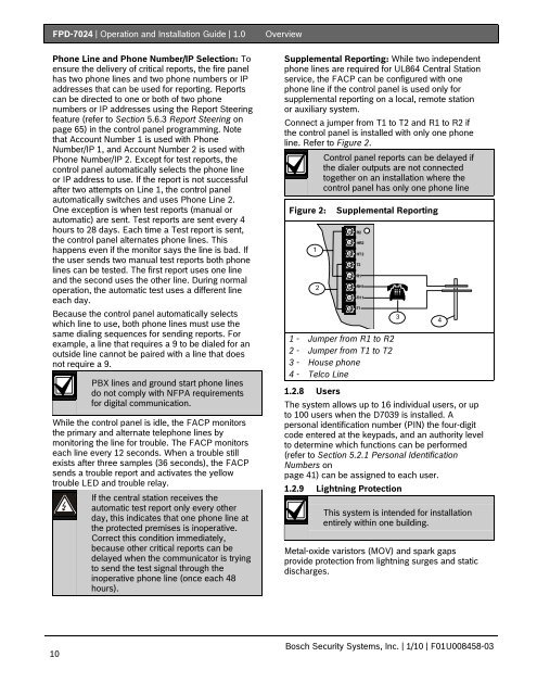
Supplemental Reporting: While two independent<br />
phone lines are required for UL864 Central Station<br />
service, the FACP can be configured with one<br />
phone line if the control panel is used only for<br />
supplemental reporting on a local, remote station<br />
or auxiliary system.<br />
Connect a jumper from T1 to T2 and R1 to R2 if<br />
the control panel is installed with only one phone<br />
line. Refer to Figure 2.<br />
Control panel reports can be delayed if<br />
the dialer outputs are not connected<br />
together on an installation where the<br />
control panel has only one phone line<br />
Figure 2: Supplemental Reporting<br />
1<br />
2<br />
R2<br />
HR2<br />
HT2<br />
T2<br />
R1<br />
RH1<br />
TH 1<br />
1 - Jumper from R1 to R2<br />
2 - Jumper from T1 to T2<br />
3 - House phone<br />
4 - Telco Line<br />
T1<br />
1.2.8 Users<br />
The system allows up to 16 individual users, or up<br />
to 100 users when the D7039 is installed. A<br />
personal identification number (PIN) the four-digit<br />
code entered at the keypads, and an authority level<br />
to determine which functions can be performed<br />
(refer to Section 5.2.1 Personal Identification<br />
Numbers on<br />
page 41) can be assigned to each user.<br />
1.2.9 Lightning Protection<br />
Bosch <strong>Security</strong> <strong>Systems</strong>, Inc. | 1/10 | F01U008458-03<br />
3<br />
This system is intended for installation<br />
entirely within one building.<br />
Metal-oxide varistors (MOV) and spark gaps<br />
provide protection from lightning surges and static<br />
discharges.<br />
4