Exeter trauma stem hip hemiarthroplasty
Exeter trauma stem hip hemiarthroplasty
Exeter trauma stem hip hemiarthroplasty
You also want an ePaper? Increase the reach of your titles
YUMPU automatically turns print PDFs into web optimized ePapers that Google loves.
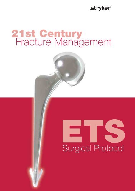
21st Century<br />
Fracture Management<br />
ETS<br />
Surgical Protocol
ETS Operative Technique<br />
Step 1<br />
Confirm that a cemented<br />
<strong>hemiarthroplasty</strong> is indicated.<br />
An X-ray template of the ETS is<br />
provided. This should be used as a<br />
guide with the pre-operative X-ray,<br />
comparing both affected and contra<br />
lateral <strong>hip</strong>s. Particular care should be<br />
made regarding the likely <strong>stem</strong><br />
insertion depth in relation to the tip of<br />
the greater trochanter. (Figure 1).<br />
Pre-op templating is strongly<br />
recommended to assess the correct<br />
level of insertion. The easiest and most<br />
reliable way to do this is to template<br />
against the opposite, unfractured <strong>hip</strong><br />
on the AP pelvis X-ray. After placing<br />
the template over the upper femur,<br />
note the position of the shoulder of<br />
the prosthesis relative to the tip of the<br />
greater trochanter. On average this is<br />
about 12mm below the tip of the<br />
trochanter, but will be less in valgus<br />
<strong>hip</strong>s, and more in varus.<br />
Step 2<br />
The patient is positioned and prepared on the<br />
operating table in the usual manner. Expose the <strong>hip</strong><br />
joint using your preferred surgical approach<br />
for <strong>hemiarthroplasty</strong>. (Figure 2).<br />
NOTE: The authors recommend an anterolateral<br />
approach 1 in the majority of cases.<br />
Figure 2 Patient position.<br />
Figure 3 Cut neck at desired level. Figure 4 Measure head size.<br />
Step 3<br />
Following exposure of the <strong>hip</strong>, cut the<br />
femoral neck 1 to 1.5cm above the<br />
lesser trochanter. The exact level and<br />
orientation of neck cut is not critical<br />
as the ETS has no collar or other<br />
features which will affect the<br />
osteotomy line. (Figure 3).<br />
Remove and measure the femoral head<br />
or alternatively use an appropriate<br />
instrument to estimate the size of the<br />
acetabulum. (Figure 4).<br />
Figure 1 X-ray with overlying template.<br />
The ETS is a relatively slim <strong>stem</strong> with a 40mm offset, suitable for the majority of<br />
cases. However, a small number of patients may have size or offset that is<br />
significantly different. If pre-op templating suggests that this is the case, any of the<br />
<strong>stem</strong>s in the <strong>Exeter</strong> range (from 30mm to 50mm offset and from 0 to 5 <strong>stem</strong><br />
size) can be combined with a UHR bipolar head to create a modular<br />
<strong>hemiarthroplasty</strong>. The similarities between the ETS and the <strong>Exeter</strong> <strong>stem</strong> make<br />
this a straight forward process for even the less experienced surgeon and theatre<br />
team. This is not an option with other commonly used hemiarthroplasties, such<br />
as the Thompsons or Austin-Moore.
Step 4<br />
Ensuring that the gluteus medius<br />
tendon is retracted and protected,<br />
a box chisel is used to open the<br />
proximal femur. This should be<br />
positioned laterally and posteriorly<br />
to gain exposure in line with the<br />
femoral canal. (Figure 5).<br />
Step 5<br />
The taper pin reamer is used to open<br />
up the femoral canal. Ensure that it<br />
is directed in a neutral position down<br />
the axis of the femur. Aim at the centre<br />
of the patella if an anterior approach<br />
is being used or, alternatively the<br />
popliteal fossa if a posterior approach<br />
is used. (Figure 6).<br />
Figure 6 Taper pin reamer used<br />
to open femoral canal.<br />
Step 7<br />
Using the rasp as a guide, mark the<br />
cut surface of the femoral neck at<br />
the desired <strong>stem</strong> insertion depth,<br />
using methylene blue or with<br />
diathermy forceps. Likewise the<br />
shoulder of the rasp can also be used<br />
as a reference. (Figure 8).<br />
Figure 8<br />
Mark femoral neck.<br />
Step 6<br />
Figure 5 Box chisel positioned laterally<br />
and posteriorly.<br />
Proximal femur preparation is made with a modular rasp.<br />
The rasp should be inserted with the required amount of anteversion; typically<br />
this is between 0° and 20° depending on the preferred approach.<br />
After rasping the femur, the <strong>Exeter</strong> V40 rasp handle is removed, leaving the<br />
rasp in the femur.<br />
Option : if the rasp is unstable in the cavity, the trial locating pin may be used<br />
to help keep the rasp at the appropriate depth position<br />
Select the appropriate trial head diameter and place the adaptor in it (figure 1a).<br />
Screw it together manually or with the ETS <strong>stem</strong> pusher (figure 1b-3b).<br />
Place the trial head plus adaptor onto the rasp neck (figure 2a) and reduce the<br />
<strong>hip</strong> to allow assessment of leg length and stability.<br />
When dislocating the <strong>hip</strong>, avoid applying undue rotational force to the femur. It is<br />
recommended to use a bone hook placed around the rasp neck to aid dislocation. If<br />
necessary, the trunnion of the rasp can be removed from the trial head adaptor<br />
(figure 3a) and the <strong>hip</strong> dislocated leaving the trial head in the acetabulum. The trial<br />
head is then removed separately. The <strong>stem</strong> pusher may be used to help this removal<br />
(figure 1b).<br />
Figure 1a Figure 2a Figure 3a<br />
To remove the adaptor from the trial head after the trial reduction:<br />
- place the trial head and adaptor assembly onto the <strong>stem</strong> pusher (figure 1b).<br />
- hold the <strong>stem</strong> pusher with one hand and unscrew the head with the other hand<br />
(figure 2b).<br />
Figure 1b Figure 2b Figure 3b
Figure 9 Stem with<br />
centraliser on.<br />
Step 8<br />
Proceed with the preferred method<br />
of cementing technique.<br />
(Modern cementing techniques are<br />
recommended, including the use of<br />
a distal cement plug, thorough lavage<br />
and drying of the canal and retrograde<br />
filling with a cement gun).<br />
Stem Pusher.<br />
Step 9<br />
Revision<br />
In the event of revision of the<br />
<strong>hemiarthroplasty</strong> to a total <strong>hip</strong><br />
replacement, the ETS can be tapped<br />
back out of the cement mantle after<br />
clearing any cement or fibrous tissue<br />
from over the shoulder of the<br />
prosthesis.<br />
Prior to insertion of the <strong>stem</strong>, the<br />
cement centraliser should be placed<br />
on the distal <strong>stem</strong> tip. (Figure 9).<br />
Both a winged and wingless cement<br />
centraliser are included with the<br />
prosthesis. For a canal size of 10mm<br />
or less, the wingless centraliser should<br />
be used.<br />
The ETS is a slim component and is collarless. As a result there is greater freedom<br />
of position when it is being inserted. As the <strong>stem</strong> is collarless, <strong>stem</strong> position is not<br />
influenced by the neck cut, and it is a simple matter to adjust for leg length by<br />
either increasing or decreasing the distance of <strong>stem</strong> insertion. However, for just<br />
the same reasons, it is also possible if care is not taken to unduly lengthen or<br />
shorten the leg by over or under insertion of the <strong>stem</strong>.<br />
Unlike a Thompsons or Austin-Moore, which is simply inserted until the collar<br />
hits the neck cut, with the ETS the surgeon needs to make a positive decision as to<br />
the correct distance of <strong>stem</strong> insertion.<br />
The <strong>stem</strong> is inserted to the previously determined level in Step 7, using the <strong>stem</strong><br />
insertion instrument. Place a thumb over the cement in the calcar, to maintain<br />
pressure during <strong>stem</strong> insertion.<br />
The <strong>stem</strong> should be inserted with the chosen degree of anteversion as previously<br />
determined in Step 6.<br />
As the ETS is slim distally, it is free to rotate in the proximal femur, and the<br />
surgeon must hold the <strong>stem</strong> in the required degree of anterversion until the<br />
cement sets. If the surgeon fails to do so, soft tissue impingement against the<br />
prosthetic head may push it into excessive anteversion, or the weight of the head<br />
can cause it to rotate into retroversion.<br />
Step 10<br />
Reduce the <strong>hip</strong>, and after confirming<br />
stability and a concentric reduction,<br />
close the wound in a routine fashion.<br />
After acetabular preparation a size 0<br />
(44mm or 37.5mm offset) <strong>Exeter</strong><br />
<strong>stem</strong> can easily be recemented into<br />
the original cement mantle.
Modular Rasp Instrumentation<br />
Catalogue No. Designation<br />
1150-2338<br />
to Unipolar/bipolar trials.<br />
1150-2356 Diameter 38mm to diameter 56mm.<br />
0590-3-211 ETS Trial rasp adaptor<br />
0590-3-210 ETS Trial rasp<br />
0570-9-000 Trial location pin<br />
0930-9-005 <strong>Exeter</strong> V40 rasp handle<br />
0590-3-230 Stem pusher
ETS Instruments & Implants<br />
Implants<br />
Cat No. Head Diameter<br />
mm<br />
0590 3 038 38<br />
0590 3 040 40<br />
0590 3 041 41<br />
0590 3 042 42<br />
0590 3 043 43<br />
0590 3 044 44<br />
0590 3 045 45<br />
0590 3 046 46<br />
0590 3 047 47<br />
0590 3 048 48<br />
0590 3 049 49<br />
0590 3 050 50<br />
0590 3 052 52<br />
0590 3 054 54<br />
0590 3 056 56<br />
Instruments<br />
Cat No. Description<br />
0590 3 240 Femoral Head<br />
Extractor<br />
0590 3 250 Skid<br />
0932 0 000 <strong>Exeter</strong> Taper<br />
Pin Reamer small<br />
0590 3 260 Instrument Tray<br />
4842 3 012 Box Chisel 12mm<br />
Head Gauges<br />
0590 3 270 Small<br />
(38, 40, 41, 42, 43mm)<br />
0590 3 280 Medium<br />
(44, 45, 46, 47, 48mm)<br />
0590 3 290 Large<br />
(49, 50, 52, 54, 56mm)<br />
0937 3 200 Stem Seal<br />
Backing Plate<br />
ETSTP01E01 X-ray Template
Notes
Acknowledgments:<br />
Published in collaboration with the following contributing surgeons:<br />
G A Gie FRCS, A J Timperley FRCS, M J W Hubble FRCS. Princess Elizabeth Orthopedic Centre, <strong>Exeter</strong><br />
References:<br />
1. Hardinge K. The direct lateral approach to the <strong>hip</strong>. J Bone Joint Surg, 1982, 64B:17-19<br />
The information presented in this brochure is intended to demonstrate a Stryker product. Always refer to the<br />
package insert, product label and/or user instructions before using any Stryker product. Products may not be<br />
available in all markets. Product availability is subject to the regulatory or medical practices that govern<br />
individual markets. Please contact your Stryker representative if you have questions about the availability<br />
of Stryker products in your area.<br />
Products referenced with a designation are trademarks of Stryker<br />
Products referenced with a ® designation are registered trademarks of Stryker<br />
Literature Number: ETSOT05E02<br />
MTX/GS 05/07<br />
Copyright ©2007 Stryker<br />
Printed in US<br />
Stryker SA<br />
Cité Centre<br />
Grand-rue 90<br />
1820 Montreux<br />
Switzerland<br />
t: +41 21 966 12 01<br />
f: +41 21 966 12 00<br />
www.europe.stryker.com


