Trigen Meta Nail Retrograde Femoral Nail Technique.pdf
Trigen Meta Nail Retrograde Femoral Nail Technique.pdf
Trigen Meta Nail Retrograde Femoral Nail Technique.pdf
Create successful ePaper yourself
Turn your PDF publications into a flip-book with our unique Google optimized e-Paper software.
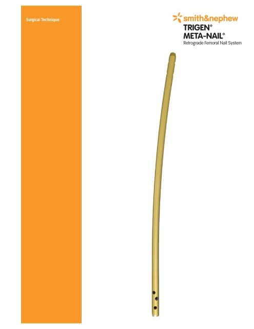
Surgical <strong>Technique</strong>
TRIGEN META-NAIL <strong>Retrograde</strong> <strong>Femoral</strong> <strong>Nail</strong> System<br />
Surgical <strong>Technique</strong><br />
Table of Contents<br />
Indications..............................................................................................................2<br />
Implant Specifications ..........................................................................................3<br />
Surgical <strong>Technique</strong><br />
Patient Positioning ........................................................................................................4<br />
Incision and Entry Point ................................................................................................6<br />
Entry Point: Portal Acquisition........................................................................................7<br />
Entry Portal ....................................................................................................................8<br />
Alternative <strong>Technique</strong>: Entry Portal................................................................................8<br />
Fracture Reduction ........................................................................................................10<br />
Reducer Removal ..........................................................................................................11<br />
Implant Measurement....................................................................................................11<br />
Unreamed <strong>Technique</strong> ....................................................................................................12<br />
Reamed <strong>Technique</strong> ........................................................................................................13<br />
<strong>Nail</strong> Assembly ................................................................................................................15<br />
<strong>Nail</strong> Insertion..................................................................................................................16<br />
Check <strong>Nail</strong> Depth ..........................................................................................................17<br />
Blocking Screw Insertion <strong>Technique</strong><br />
Incision and Entry Point ................................................................................................19<br />
Entry Portal Acquisition..................................................................................................19<br />
AP Blocking Screw Insertion..........................................................................................20<br />
ML Blocking Screw Insertion..........................................................................................21<br />
Blocking Screw Insertion With Reducer ........................................................................22<br />
Stability Blocking Screw Insertion..................................................................................23<br />
Locking Screw Measurement ........................................................................................26<br />
Locking Screw Insertion ................................................................................................26<br />
Proximal Locking ............................................................................................................27<br />
<strong>Nail</strong> Cap and <strong>Nail</strong> Cap Set Screw Insertion ..................................................................28<br />
<strong>Nail</strong> Extraction<br />
Standard <strong>Technique</strong> ......................................................................................................30<br />
Percutaneous <strong>Technique</strong> ..............................................................................................30<br />
Guide Rod Jamming <strong>Technique</strong> ....................................................................................31<br />
Catalog Information ..............................................................................................32<br />
Nota Bene<br />
The technique description herein is made available to the healthcare professional to illustrate the<br />
authors' suggested treatment for the uncomplicated procedure. In the final analysis, the preferred<br />
treatment is that which addresses the needs of the patient.<br />
1
Indications<br />
The TRIGEN META-NAIL <strong>Retrograde</strong> <strong>Femoral</strong><br />
<strong>Nail</strong> is indicated for fractures of the femur<br />
including stable and unstable distal metaphyseal<br />
fractures, diaphyseal fractures, intra-articular<br />
fractures, peri-prosthetic fractures, non-unions,<br />
mal-unions and for the prophylactic nailing of<br />
impending pathological fractures.<br />
2
TRIGEN META-NAIL <strong>Retrograde</strong> <strong>Femoral</strong><br />
<strong>Nail</strong> Specifications<br />
ML View<br />
R 2M<br />
100mm<br />
Non-driving End of <strong>Nail</strong><br />
Top View of <strong>Nail</strong><br />
Driving End of <strong>Nail</strong><br />
NOTE: These views are not to scale and should be used as a<br />
pictorial representation only.<br />
* Set does not include all sizes; Outlier sizes may be special order only<br />
Specifications TRIGEN META-NAIL <strong>Retrograde</strong> <strong>Femoral</strong><br />
Material TI6AL4V<br />
Diameter 10, 11.5 & 13mm<br />
Lengths 18-50cm*<br />
<strong>Nail</strong> Color Gold<br />
Cross Section Round<br />
Distal Diameter<br />
(driving end)<br />
Proximal Diameter<br />
(non-driving end)<br />
Smallest Thru Diameter 5.0mm<br />
Wall Thickness<br />
12mm (10, 11.5 dia)<br />
13mm (13 dia)<br />
10, 11.5 & 13mm<br />
2.3mm (10 dia)<br />
3.0mm (11.5 dia)<br />
2.3mm (13 dia)<br />
Guide Bolt Thread 5/16-24 UNF<br />
Screw Diameter 5.0mm<br />
Screw Color Gold<br />
Major Diameter 5.0mm<br />
Minor Diameter (core) 4.3mm<br />
Screw Lengths 25-110mm<br />
Hex Size 4.7mm<br />
Alternative Hex Drivers<br />
Alternative Modes No<br />
Distal Locking (Driving End)<br />
Static Lock<br />
Locations/Orientations<br />
Static Locking Hole<br />
Dimensions<br />
Proximal Locking<br />
(Non-Driving End)<br />
Static Lock Locations/<br />
Orientations<br />
Static Locking Hole<br />
Dimensions<br />
Proximal Screw Hole<br />
Diameter<br />
AP Bow Radius 2M<br />
RT <strong>Femoral</strong> & Recon<br />
7.0mm Cannulated Screw<br />
PER-LOC 4.7mm Hex driver, PROFIX 4.7mm Hex Driver<br />
15mm/ML - Threaded, Can be locked with META-NAIL Cap<br />
30mm/25° - Threaded w/bushing<br />
40mm/25° - Threaded w/bushing<br />
Threaded 4.5mm minor dia.<br />
Threaded 5.3mm major dia.<br />
15mm/AP<br />
35mm/AP<br />
5.3mm<br />
5.3mm<br />
AP Bow Location Starts 100mm from Driving End<br />
3
Surgical <strong>Technique</strong><br />
Patient Positioning<br />
Position the patient supine on a radiolucent<br />
table. Flex the affected limb approximately 45°<br />
over a posterior support to assist with fracture<br />
reduction. Check for length and rotation by<br />
comparison to the unaffected limb.<br />
Rotate the C-Arm to ensure optimal AP and<br />
lateral visualization of the entire femur. The<br />
C-Arm should be able to freely access the femur<br />
up to and including the intertrochanteric area.<br />
A distraction device may also be applied to<br />
obtain and/or maintain traction.<br />
Intra-articular fracture components should be<br />
addressed with interfragmentary screw fixation<br />
prior to nail insertion. Care should be taken to<br />
place the screws in the anterior and posterior<br />
aspect of the distal femur and safely out of the<br />
nail's intended path.<br />
Note: Cannulated screw guide wires allow for<br />
confirmation of definitive screw placement prior<br />
to fracture fixation and nail insertion.<br />
4
Instruments for Opening the Distal Femur<br />
3.2mm Tip Threaded Guide Wire<br />
Cat. No. 7163-1690<br />
12.5mm Entry Reamer<br />
Cat. No. 7163-1116<br />
Honeycomb<br />
Cat. No. 7167-4075<br />
Entry Portal Tube<br />
Cat. No. 7167-4060<br />
Entry Portal Handle<br />
Cat. No. 7167-4092<br />
3.2mm T-Handle Trocar<br />
Cat. No. 7167-4074<br />
Cannulated Awl<br />
Cat. No. 7167-4000<br />
Mini Connector<br />
Cat. No. 7163-1186<br />
T-Handle<br />
Cat. No. 7167-4076<br />
5
Surgical <strong>Technique</strong> (continued)<br />
Incision and Entry Point<br />
Assemble the Honeycomb (7167-4075), Entry<br />
Handle (7167-4092) and Entry Tube (7167-4060).<br />
The pieces will lock in place securely at either<br />
0° or 180°.<br />
A 3-4cm midline incision is made followed by a<br />
medial parapatellar capsular incision to expose<br />
the intercondylar notch. Gently retract the<br />
patellar tendon laterally.<br />
The entry point is located within the<br />
intercondylar notch just anterior and lateral<br />
to the femoral attachment of the posterior<br />
cruciate ligament.<br />
6
Entry Portal Acquisition<br />
Attach a 3.2mm Tip Threaded Guide Wire<br />
(7163-1690) to the drill via the Mini Connector<br />
(7163-1186) and insert 6-8cm into the<br />
distal femoral metaphysis. The Entry<br />
Portal Instrumentation serves as a soft<br />
tissue protector.<br />
The Guide Wire should be in-line with the<br />
femoral axis in the AP view and anterior to<br />
Blumensaat's Line in the lateral.<br />
In the instance of suboptimal Wire placement,<br />
rotate the Honeycomb within the Entry Tube to<br />
the desired location and insert another 3.2mm<br />
Tip Threaded Guide Wire.<br />
Blumensaat’s Line<br />
7
Surgical <strong>Technique</strong> (continued)<br />
Entry Portal<br />
After definitive Guide Wire placement, remove<br />
the Honeycomb from the Entry Tube along with<br />
any additionally inserted Guide Wires and attach<br />
the 12.5mm Entry Reamer to power. Advance<br />
over the Guide Wire through the Entry Tube to<br />
a depth of 6-8cm.<br />
Check position via radiographic imaging and<br />
then remove the 12.5mm Entry Reamer and<br />
3.2mm Tip Threaded Guide Wire.<br />
Alternative <strong>Technique</strong>:<br />
Entry Portal<br />
Attach the T-Handle (7167-4076) to the<br />
Cannulated Awl (7167-4000) and insert into the<br />
distal femur to a depth of 6-8cm. Introduce the<br />
3.2mm T-Handle Trocar (7167-4074) into the<br />
back of the assembly prior to insertion in order<br />
to prevent awl slippage and accumulation of<br />
cortical bone within the cannulation.<br />
8<br />
Cannulated Awl<br />
with T-Handle<br />
3.2mm T-Handle<br />
Trocar
Instruments for Fracture Reduction & Reaming<br />
Entry Portal Tube<br />
Cat. No. 7167-4060<br />
Ruler<br />
Cat. No. 7167-4079<br />
T-Handle<br />
Cat. No. 7167-4076<br />
Reamer Heads<br />
Cat. No. 7111-8231–8246<br />
Entry Portal Handle<br />
Cat. No. 7167-4092<br />
Obturator<br />
Cat. No. 7167-4078<br />
Reamer Shaft<br />
Cat. No. 7111-8200<br />
Reducer<br />
Cat. No. 7167-4077<br />
3.0mm Ball-Tip Guide Rod<br />
Cat. No. 7163-1626<br />
Gripper<br />
Cat. No. 7163-1186<br />
9
Surgical <strong>Technique</strong> (continued)<br />
Fracture Reduction<br />
Insert the back end of the 3.0mm Ball Tip Guide<br />
Rod (7163-1626) into the front of the Gripper<br />
(7167-4080) and gently close the trigger-grip.<br />
Connect the Reducer and Reducer Connector<br />
(7167-4077) so that the words “Slot Orientation”<br />
are in line with the opening at the tip. Complete<br />
the assembly by connecting it to the T-Handle.<br />
Note: If blocking screws are desired at this point<br />
in the procedure, refer to the blocking screws<br />
technique section (pp. 18-24).<br />
Advance the Reducer into the intramedullary<br />
canal and use the curved tip to direct the<br />
3.0mm Ball Tip Guide Rod past the fracture into<br />
the region of the proximal femur.<br />
The Guide Rod should be center-center in the<br />
AP and lateral views.<br />
10
Reducer Removal<br />
Once the Guide Rod is at the desired depth,<br />
detach the Gripper and remove the Reducer<br />
from the femoral canal. Slide the Obturator<br />
(7167-4078) into the back of the T-Handle during<br />
extraction in order to maintain Guide Rod<br />
position within the canal.<br />
Implant Measurement<br />
After Reducer removal, re-confirm Guide Rod<br />
placement within the proximal femur and slide<br />
the Ruler (7167-4079) over the Guide Rod to the<br />
desired depth. The metal tip of the Ruler<br />
denotes the driving end of the META-NAIL<br />
<strong>Retrograde</strong> <strong>Femoral</strong> <strong>Nail</strong>.<br />
Confirm Guide Rod position in the window at the<br />
opposite end of the Ruler as shown in order to<br />
ensure accurate implant measurement. Push<br />
down on the top of Ruler until contact is made<br />
with the 3.0mm Guide Rod. Implant length is<br />
read from the exposed calibrations at the end of<br />
the ruler.<br />
Note: Implant length selection should take into<br />
consideration the fact that the nail must be<br />
countersunk past the articular surface of the<br />
distal femur.<br />
Note: Confirm that the Ruler opens easily and<br />
adjust the thumb-wheel connection at the end<br />
to allow for free movement.<br />
11
Surgical <strong>Technique</strong> (continued)<br />
Unreamed <strong>Technique</strong><br />
Radiographic templating is used to determine<br />
nail size. The appropriate diameter implant will<br />
provide translational fill within the isthmus of the<br />
intramedullary canal. Generally, selection of a<br />
nail at least 1-1.5mm less than the narrowest<br />
canal measurement on the lateral radiograph<br />
assists in avoiding implant incarceration<br />
during insertion.<br />
Note: The 7.6mm diameter of the Reducer<br />
provides an initial “sound” for determining canal<br />
width in small diameter femurs.<br />
12<br />
TRIGEN META-NAIL <strong>Femoral</strong> <strong>Retrograde</strong> <strong>Nail</strong><br />
Radiographic Template<br />
Cat. No. 7118-0811
Reamed <strong>Technique</strong><br />
Radiographic templating and intra-operative<br />
measurement will determine nail size. Beginning<br />
with the 9.0mm Front Cutting Reamer Head<br />
(7111-8231) and Flexible Reamer Shaft<br />
(7111-8200), ream the intramedullary canal<br />
sequentially in half millimeter increments to a<br />
size 1-1.5mm larger than the selected nail size.<br />
Ensure Guide Rod placement during reaming by<br />
inserting the Obturator into the back of the<br />
Reamer unit during retraction. Continue to<br />
confirm Guide Rod placement in the proximal<br />
femur throughout reaming. Periodically move the<br />
reamer back and forth in the canal to clear<br />
debris from the cutting flutes.<br />
13
Surgical <strong>Technique</strong> (continued)<br />
Instruments for <strong>Nail</strong> Assembly & Insertion<br />
Guide Bolt Wrench<br />
Cat. No. 7163-1140<br />
META-NAIL Drill Guide<br />
Cat. No. 7165-4502<br />
Guide Bolt Long<br />
Cat. No. 7165-45061<br />
Short Impactor<br />
Cat. No. 7165-4521<br />
T-Handle<br />
Cat. No. 7167-4076<br />
* 4.0mm Long Pilot Drill (7163-1110) is interchangeable with 4.0mm AO Long Drill (7163-1121)<br />
14<br />
META-NAIL Anterior Drop<br />
Cat. No. 7165-4501<br />
9.0mm Drill Sleeve<br />
Cat. No. 7163-1152<br />
4.0mm Drill Sleeve<br />
Cat. No. 7167-4083<br />
4.0mm Long Pilot Drill*<br />
Cat. No. 7163-1110<br />
Impactor<br />
Cat. No. 7167-4081<br />
Slotted Hammer<br />
Cat. No. 7167-4082
<strong>Nail</strong> Assembly<br />
Attach the META-NAIL Drill Guide (7165-4502)<br />
to the nail with the Guide Bolt Long (7165-4506)<br />
and tighten with the Guide Bolt Wrench<br />
(7163-1140) and T-Handle. The nail is correctly<br />
aligned when:<br />
1. The line on the insertion barrel matches the line<br />
on the back of the nail<br />
2.The “A” on the nail matches the “A” on the<br />
insertion barrel<br />
3.The apex of the nail’s AP Bow and the Drill<br />
Guide itself are oriented anterior<br />
The bevel on the front of the nail marks the<br />
connection to the Drill Guide and can be seen in<br />
the lateral view as a means for determining<br />
distal insertion depth.<br />
Note: Do not use the META-NAIL Extension<br />
Drill Guide to insert the <strong>Retrograde</strong> <strong>Femoral</strong><br />
<strong>Nail</strong> as the Insertion Barrel is too short to allow<br />
for adequate countersinking of the nail. It is<br />
recommended to use the standard Drill Guide<br />
and Long Guide Bolt due to the longer<br />
Insertion Barrel.<br />
Attach the Anterior Drop (7165-4501) to the Drill<br />
Guide and verify targeting accuracy by inserting<br />
a gold 9.0mm Drill Sleeve (7163-1152) and silver<br />
4.0mm Drill Sleeve (7167-4083) into the Drop<br />
and passing a 4.0mm Long Pilot Drill (7163-1110)*<br />
through the assembly. An incorrectly attached<br />
nail will not target.<br />
* 4.0mm Long Pilot Drill (7163-1110) is interchangeable with 4.0mm AO Long Drill (7163-1121)<br />
15
Surgical <strong>Technique</strong> (continued)<br />
<strong>Nail</strong> Insertion<br />
Remove the Anterior Drop and attach the<br />
Impactor (7167-4081) to the Drill Guide. Orient<br />
the Drill Guide assembly in the AP position and<br />
advance the nail over the Guide Rod by light<br />
blows from the Slotted Hammer (7167-4082) to<br />
the desired depth.<br />
Additional reaming of the intramedullary canal<br />
may be necessary if excessive force is required<br />
to insert the nail.<br />
Verify fracture reduction as the nail crosses the<br />
fracture site paying close attention to rotation,<br />
length, alignment, distraction and/or shortening.<br />
Check final nail position in both the AP and<br />
lateral views for correct alignment.<br />
16
Check <strong>Nail</strong> Depth<br />
Distal<br />
In the AP and lateral views, confirm nail position<br />
within the distal femur. The notch at the nail/Drill<br />
Guide junction will be visible in the lateral. Each<br />
gauge on the insertion barrel represents a<br />
10mm depth interval.<br />
Proximal<br />
In the AP view, confirm that the nail has been<br />
inserted to the desired depth. <strong>Femoral</strong> fractures<br />
should be treated with the longest nail possible<br />
in order to reduce the likelihood of stress risers.<br />
Remove the Guide Rod once the nail has been<br />
fully seated and attach the Anterior Drop.<br />
Note: Following nail insertion, confirm that the<br />
nail and Drill Guide are securely connected as<br />
hammering can loosen the Guide Bolt.<br />
17
Surgical <strong>Technique</strong> (continued)<br />
Instruments for Standard Locking<br />
Long Screw Length Sleeve<br />
Cat. No. 7165-4520<br />
Medium Hexdriver<br />
Cat. No. 7163-1066<br />
4.0mm Drill Sleeve<br />
Cat. No. 7163-1156<br />
9.0mm Drill Sleeve<br />
Cat. No. 7163-1152<br />
4.0mm Long Pilot Drill*<br />
Cat. No. 7163-1110<br />
T-Handle<br />
Cat. No. 7167-4076<br />
* 4.0mm Long Pilot Drill (7163-1110) is interchangeable with 4.0mm AO Long Drill (7163-1121)<br />
** 4.0mm Short Drill (7163-1117) is interchangeable with 4.0mm AO Short Drill (7163-1123)<br />
18<br />
<strong>Nail</strong> Cap Set Screw<br />
Cat. No. 7165-6000<br />
Screw Depth Gauge<br />
Cat. No. 7163-1189<br />
META-NAIL Anterior Drop<br />
Cat. No. 7165-4501<br />
Mini Connector<br />
Cat. No. 7163-1186<br />
Screwdriver Release<br />
Cat. No. 7167-4084<br />
4.0mm Short Drill**<br />
Cat. No. 7163-1117
Locking Screw Measurement<br />
There are three (3) methods:<br />
1. Gold 9.0mm Drill Sleeve, silver 4.0mm Drill<br />
Sleeve and 4.0mm Long Pilot Drill*<br />
2.Screw Depth Gauge (7163-1189)<br />
3.Long Screw Length Sleeve (7165-4520) and<br />
4.0mm Long Pilot Drill*<br />
Locking Screw Insertion<br />
Distal locking options include three (3) statically<br />
locked threaded holes that are targeted through<br />
the orange and green color-coded holes on the<br />
Anterior Drop.<br />
Proximal locking options include two (2) statically<br />
locked, non-threaded AP holes.<br />
Gold 5.0mm locking screws are compatible with<br />
10, 11.5 and 13mm diameter nails.<br />
Note: The 4.0mm Short Step Drill (7164-1123)<br />
may be used to drill for a gold 5.0mm locking<br />
screw in the instance of hard cortical bone.<br />
Its 4.7-4.0mm width transition facilitates easier<br />
screw insertion without compromising purchase.<br />
* 4.0mm Long Pilot Drill (7163-1110) is interchangeable with 4.0mm AO Long Drill (7163-1121)<br />
3<br />
1<br />
2<br />
19
Surgical <strong>Technique</strong> (continued)<br />
Distal Locking<br />
Make a small incision at the site of screw entry<br />
and insert the gold 9.0mm Drill Sleeve and silver<br />
4.0mm Drill Sleeve through the desired slot on<br />
the Anterior Drop down to bone. Drill both<br />
cortices with the 4.0mm Long Pilot Drill*.<br />
Measure for screw length using either the<br />
calibrations on the 4.0mm Long Pilot Drill* or<br />
by removing the 4.0mm Drill Sleeve and using<br />
the Screw Depth Gauge. Attach the appropriate<br />
length screw to the end of the Medium<br />
Hexdriver (7163-1066) and insert through the<br />
gold 9.0mm Drill Sleeve on power until the laser<br />
etched ring on the Hexdriver reached the back<br />
of the Drill Sleeve. Attach the T-Handle to the<br />
Hexdriver and tighten the screw by hand.<br />
Proximal Locking<br />
Proximal locking is performed in the AP plane<br />
using a free-hand technique. Confirm fracture<br />
reduction and align the C-Arm over the desired<br />
locking hole. Obtain a “perfect circle” image of<br />
the locking hole and use a blunt object to<br />
approximate the location of the locking hole by<br />
dimpling the skin.<br />
Make a stab incision at the site, insert the<br />
4.0mm Long Pilot Drill*, and drill both cortices.<br />
Measure for screw length using the Screw<br />
Depth Gauge. Alternatively, leave the 4.0mm<br />
Long Pilot Drill* in place, insert the Long Screw<br />
Length Sleeve down to bone, and read the<br />
exposed calibrations off the drill. Insert the<br />
appropriate length screw using the Medium<br />
Hexdriver/T-Handle assembly.<br />
* 4.0mm Long Pilot Drill (7163-1110) is interchangeable with 4.0mm AO Long Drill (7163-1121)<br />
20
Surgical <strong>Technique</strong> (continued)<br />
Instruments for Blocking Screw Insertion<br />
<strong>Retrograde</strong> <strong>Femoral</strong><br />
Blocking Screw<br />
Attachment<br />
Cat. No. 7165-4508<br />
T-Handle<br />
Cat. No. 7167-4076<br />
11.0mm T-Handle<br />
Awl<br />
Cat. No. 7165-4522<br />
8.5mm/10.0mm<br />
Screw Cartridge<br />
Cat. No. 7165-4511<br />
* 4.0mm Long Pilot Drill (7163-1110) is interchangeable with 4.0mm AO Long Drill (7163-1121)<br />
11.5mm/13.0mm<br />
Screw Cartridge<br />
Cat. No. 7165-4513<br />
Blocking Screw Alignment Pin<br />
Cat. No. 7163-1110<br />
4.0mm Long Pilot Drill*<br />
Cat. No. 7163-1110<br />
4.0mm Drill Sleeve<br />
Cat. No. 7163-1156<br />
9.0mm Drill Sleeve<br />
Cat. No. 7163-1152<br />
Medium Hexdriver<br />
Cat. No. 7163-1066<br />
Offset Blocking<br />
Screw Cartridge<br />
Cat. No. 7165-4514<br />
Blocking Screw<br />
Device<br />
Cat. No. 7165-4515<br />
Mini Connector<br />
Cat. No. 7163-1186<br />
21
Blocking Screw <strong>Technique</strong>:<br />
Incision & Entry Point<br />
A 3-4cm midline incision is made followed by a<br />
medial parapatellar capsular incision to expose<br />
the intercondylar notch. Gently retract the<br />
patellar tendon laterally.<br />
The entry point is located within the<br />
intercondylar notch just anterior and lateral to<br />
the femoral attachment of the posterior<br />
cruciate ligament.<br />
Entry Portal Acquisition<br />
Insert the 11.0mm T-Handle Awl (7165-4522)<br />
manually to a depth just distal to the fracture.<br />
Note: When creating the initial entry point, pay<br />
close attention to the trajectory of the Awl and<br />
it’s relationship to the anatomic axis of the femur.<br />
Correct Awl trajectory in the distal fragment<br />
must be established prior to alignment with the<br />
anatomic axis of the proximal fragment. This will<br />
ensure accurate fracture reduction when the nail<br />
is inserted.<br />
22
AP Blocking Screw Insertion<br />
In order to prevent varus or valgus malalignment<br />
of the distal fragment, blocking screws may be<br />
placed in the AP plane. Attach the Blocking<br />
Screw Device (7165-4515) to the 11.0mm<br />
T-Handle Awl and move it into the desired<br />
position in the AP plane.<br />
Note: The Blocking Screw Alignment Pins<br />
(7165-4523) can be screwed into the three (3)<br />
threaded holes on the metal handle of the<br />
Blocking Screw Device to serve as external<br />
points of reference during fracture alignment.<br />
Tighten the device to the Awl and insert<br />
the appropriate Blocking Screw Cartridge<br />
(7165-4511, 7165-4513, 7165-4514). Adjust the<br />
Cartridge proximally or distally within the<br />
Blocking Screw Device to determine blocking<br />
screw position.<br />
Insert the gold 9.0mm Drill Sleeve and silver<br />
4.0mm Drill Sleeve into the desired cartridge<br />
hole and down to bone. Drill both cortices with<br />
the 4.0 mm Long Pilot Drill*. Screw length is<br />
determined by reading the exposed drill bit<br />
calibrations or by removing the 4.0mm Drill<br />
Sleeve and measuring with the Screw Depth<br />
Gauge. Insert the screw with the Medium<br />
Hexdriver/T-Handle assembly until the screw<br />
engages the far cortex.<br />
Note: Use caution during drilling and insertion of<br />
blocking screws in the AP plane. Plunging<br />
the drill bit past the posterior cortex or insertion<br />
of a screw that is too long may damage<br />
neurovascular structures located posterior<br />
to the distal femur.<br />
* 4.0mm Long Pilot Drill (7163-1110) is interchangeable with 4.0mm AO Long Drill (7163-1121)<br />
23
Surgical <strong>Technique</strong> (continued)<br />
Following implantation of the distal blocking<br />
screw and fracture reduction, pass the 11.0mm<br />
T-Handle Awl into the proximal fragment.<br />
Re-position either the Blocking Screw Cartridge<br />
or the Awl as necessary and follow the<br />
previously described technique for blocking<br />
screw insertion.<br />
ML Blocking Screw Insertion<br />
In order to prevent anterior or posterior<br />
malalignment of the distal fragment, blocking<br />
screws may also be placed in the ML plane.<br />
Attach the Blocking Screw Device to the 11.0mm<br />
T-Handle Awl and rotate it into the desired<br />
position in the ML plane.<br />
Tighten the device to the Awl and insert the<br />
appropriate Blocking Screw Cartridge. Adjust<br />
the Cartridge proximally or distally within the<br />
Blocking Screw Device to determine blocking<br />
screw position. Blocking screw insertion follows<br />
the previously described technique.<br />
24
Blocking Screw Insertion<br />
with Reducer<br />
Blocking screw insertion can also be performed<br />
by attaching the Blocking Screw Device to the<br />
Reducer instead of the 11.0mm T-Handle Awl.<br />
Blocking screw insertion follows the previously<br />
described technique.<br />
Final View: AP and ML Blocking<br />
Screw Insertion<br />
Once blocking screw insertion is complete,<br />
remove the Blocking Screw Device from the<br />
11.0mm T-Handle Awl or Reducer and obtain both<br />
AP and lateral radiographic images to confirm<br />
accurate placement.<br />
The Awl or Reducer provides a good indication<br />
of the nail’s insertion trajectory based upon the<br />
location of the blocking screws. Following<br />
confirmation of proper screw placement,<br />
proceed with nail insertion following the<br />
META-NAIL system insertion technique.<br />
25
Surgical <strong>Technique</strong> (continued)<br />
Stability Blocking Screw Insertion<br />
Following nail insertion and confirmation of<br />
fracture reduction, blocking screws can be<br />
placed on either side of the nail in the<br />
metaphyseal region for additional stability.<br />
Screws may be inserted in both the AP and<br />
ML planes.<br />
With the nail inserted, attach the <strong>Retrograde</strong><br />
<strong>Femoral</strong> Blocking Screw Attachment (7165-4508)<br />
to the Anterior Drop, matching the orange shape<br />
found on the Blocking Screw Attachment to the<br />
corresponding one on the Drop (Triangle to<br />
Triangle for AP screws and Square to Square for<br />
ML screws). Follow the previously described<br />
technique for Cartridge positioning and blocking<br />
screw insertion.<br />
Note: The AP blocking screws targeted through<br />
the two (2) holes built into the Anterior Drop<br />
cannot be used if the most superior oblique<br />
distal locking screw has been inserted.<br />
26
Final View: Stability Blocking<br />
Screws<br />
Once stability blocking screw insertion is<br />
complete, remove the Blocking Screw<br />
Attachment and Anterior Drop from the<br />
Drill Guide and obtain both AP and lateral<br />
radiographic images to confirm accurate<br />
placement.<br />
TRIGEN <strong>Nail</strong> Cap and <strong>Nail</strong> Cap<br />
Set Screw Insertion: Optional<br />
Remove the Drill Guide/Anterior Drop assembly.<br />
Attach the selected <strong>Nail</strong> Cap or <strong>Nail</strong> Cap Set<br />
Screw to the Medium Hexdriver/T-Handle<br />
assembly and insert into the end of the nail<br />
until tight.<br />
Note: The TRIGEN <strong>Nail</strong> Cap does not engage<br />
with the most distal locking screws to create a<br />
fixed angle construct.<br />
Note: If cross-threading occurs, rotate the <strong>Nail</strong><br />
Cap or <strong>Nail</strong> Cap Set Screw counterclockwise<br />
until its threads line up with those of the nail.<br />
Proceed with insertion until tight.<br />
27
Surgical <strong>Technique</strong> (continued)<br />
Instruments for Implant Removal<br />
3.2mm Tip Threaded Guide Wire<br />
Cat. No. 7163-1690<br />
12.5mm Entry Reamer<br />
Cat. No. 7163-1116<br />
Impactor<br />
Cat. No. 7167-4081<br />
T-Handle<br />
Cat. No. 7167-4076<br />
Medium Hexdriver<br />
Cat. No. 7163-1066<br />
* Additional Guide Rods listed on page 30<br />
** The One Piece Impactor is located in the original TRIGEN Instrument Set (7163-1326)<br />
*** The Disposable <strong>Nail</strong> Extractor (7163-1320) is interchangeable with the Large <strong>Nail</strong> Extractor located in the original TRIGEN<br />
Instrument Set (7163-1326) and the HFN Instrument Set (7170-0001)<br />
28<br />
One Piece Impactor***<br />
Cat. No. 7163-1185<br />
Slotted Hammer<br />
Cat. No. 7167-4082<br />
Mini Connector<br />
Cat. No. 7163-1186<br />
Disposable <strong>Nail</strong> Extractor**<br />
Cat. No. 7163-1320<br />
3.0mm x 1000mm Ball Tip Guide Rod*<br />
Cat. No. 7163-1626
<strong>Nail</strong> Extraction: Optional<br />
Standard <strong>Technique</strong><br />
Remove the <strong>Nail</strong> Cap or <strong>Nail</strong> Cap Set Screw if<br />
implanted and all of the proximal locking screws<br />
with the Medium Hexdriver/T-Handle assembly.<br />
Remove all of the distal locking screws except for<br />
one in the same manner.<br />
Thread the Extraction Bolt (7163-1320) into the<br />
Impactor (7167-4081) or One Piece Impactor<br />
(7163-1185)* and introduce the extraction<br />
assembly into the end of the nail. Remove the<br />
remaining distal locking screw and then extract<br />
the nail with a back-slapping motion using the<br />
Slotted Hammer.<br />
Percutaneous <strong>Technique</strong><br />
This technique assumes the absence of a <strong>Nail</strong><br />
Cap or <strong>Nail</strong> Cap Set Screw. Remove all proximal<br />
locking screws and all but one of the distal<br />
locking screws as previously described. Under<br />
fluoroscopy, insert a 3.2mm Tip Threaded Guide<br />
Wire into the end of the nail on power or by<br />
hand. Make a 2cm incision around the Wire and<br />
advance the 12.5mm Entry Reamer over the Wire<br />
and into the end of the nail to remove any bony<br />
in-growth.<br />
Thread the Impactor or One Piece Impactor into<br />
the back of the Disposable <strong>Nail</strong> Extractor** and<br />
then thread the assembly into the end of the<br />
nail. Remove the remaining distal locking<br />
screw and then extract the nail with a backslapping<br />
motion.<br />
Note: The tip of the Entry Reamer is straight for<br />
approximately 1cm before flaring out. It is this<br />
portion of the Entry Reamer that enters the top of<br />
the nail.<br />
* The One Piece Impactor is found only in original TRIGEN Instrument Set (7163-1326)<br />
** The Disposable <strong>Nail</strong> Extractor (7163-1320) is interchangeable with the Large <strong>Nail</strong> Extractor located in the original TRIGEN Instrument<br />
Set (7163-1326) and the HFN Instrument Set (7170-0001)<br />
29
An Alternative Method for Extraction<br />
Guide Rod Jamming <strong>Technique</strong><br />
Advance the end of a 3.0mm Ball Tip Guide Rod<br />
through the end of the nail. Insert a smooth<br />
2.0mm Guide Rod (7111-8280) in the same<br />
manner. With both Guide Rods in place attach<br />
the Gripper to the end of the 3.0mm Ball Tip<br />
Guide Rod and pull it back so that it wedges the<br />
ball tip against the smooth 2.0mm Guide Rod.<br />
Backslap against the Gripper with the Slotted<br />
Hammer to extract the nail.<br />
Guide Rods<br />
Cat. No. Description<br />
7111-8280 2.0mm x 900mm Smooth<br />
(RUSSELL-TAYLOR System)*<br />
7111-8202 3.0mm x 900mm Ball Tip<br />
(RUSSELL-TAYLOR System)*<br />
7163-1626 3.0mm x 1000mm Ball Tip<br />
(TRIGEN System)<br />
Additional Removal Items<br />
Cat. No. Description<br />
115074 Large Extractor Hook*<br />
115073 Small Extractor Hook*<br />
914658 Large Easy Out**<br />
914659 Small Easy Out**<br />
* Available sterile packed. For nail removal only, do not use for nail insertion<br />
** Located in RUSSELL-TAYLOR Extraction Kit (Set #7508) available through Loaners<br />
30
Catalog Information – Implants<br />
TRIGEN Internal Captured Screws 5.0mm<br />
Set No. 7163-1321<br />
Cat. No. Length<br />
7164-2225 Internal Hex Captured Screw 5.0mm X 25mm<br />
7164-2230 Internal Hex Captured Screw 5.0mm X 30mm<br />
7164-2235 Internal Hex Captured Screw 5.0mm X 35mm<br />
7164-2240 Internal Hex Captured Screw 5.0mm X 40mm<br />
7164-2245 Internal Hex Captured Screw 5.0mm X 45mm<br />
7164-2250 Internal Hex Captured Screw 5.0mm X 50mm<br />
7164-2255 Internal Hex Captured Screw 5.0mm X 55mm<br />
7164-2260 Internal Hex Captured Screw 5.0mm X 60mm<br />
7164-2265 Internal Hex Captured Screw 5.0mm X 65mm<br />
7164-2270 Internal Hex Captured Screw 5.0mm X 70mm<br />
7164-2275 Internal Hex Captured Screw 5.0mm X 75mm<br />
TRIGEN META-NAIL 10mm <strong>Retrograde</strong> <strong>Femoral</strong><br />
Set No. 7165-1000<br />
Cat. No. Length Availability<br />
7165-3018* META-NAIL <strong>Retrograde</strong> 10mm x 18cm Outlier<br />
7165-3020* META-NAIL <strong>Retrograde</strong> 10mm x 20cm Outlier<br />
7165-3022* META-NAIL <strong>Retrograde</strong> 10mm x 22cm Outlier<br />
7165-3024* META-NAIL <strong>Retrograde</strong> 10mm x 24cm Outlier<br />
7165-3026 META-NAIL <strong>Retrograde</strong> 10mm x 26cm Outlier<br />
7165-3028 META-NAIL <strong>Retrograde</strong> 10mm x 28cm Outlier<br />
7165-3030 META-NAIL <strong>Retrograde</strong> 10mm x 30cm Implant set<br />
7165-3032 META-NAIL <strong>Retrograde</strong> 10mm x 32cm Implant set<br />
7165-3034 META-NAIL <strong>Retrograde</strong> 10mm x 34cm Implant set<br />
7165-3036 META-NAIL <strong>Retrograde</strong> 10mm x 36cm Implant set<br />
7165-3038 META-NAIL <strong>Retrograde</strong> 10mm x 38cm Implant set<br />
7165-3040 META-NAIL <strong>Retrograde</strong> 10mm x 40cm Implant set<br />
7165-3042 META-NAIL <strong>Retrograde</strong> 10mm x 42cm Implant set<br />
7165-3044 META-NAIL <strong>Retrograde</strong> 10mm x 44cm Outlier<br />
7165-3046* META-NAIL <strong>Retrograde</strong> 10mm x 46cm Outlier<br />
7165-3048* META-NAIL <strong>Retrograde</strong> 10mm x 48cm Outlier<br />
7165-3050* META-NAIL <strong>Retrograde</strong> 10mm x 50cm Outlier<br />
* Available through special order<br />
31
Catalog Information – Implants (continued)<br />
TRIGEN META-NAIL 11.5mm <strong>Retrograde</strong> <strong>Femoral</strong><br />
Set No. 7165-1001<br />
Cat. No. Length Availability<br />
7165-3218* META-NAIL <strong>Retrograde</strong> 11.5mm x 18cm Outlier<br />
7165-3220* META-NAIL <strong>Retrograde</strong> 11.5mm x 20cm Outlier<br />
7165-3222* META-NAIL <strong>Retrograde</strong> 11.5mm x 22cm Outlier<br />
7165-3224* META-NAIL <strong>Retrograde</strong> 11.5mm x 24cm Outlier<br />
7165-3226 META-NAIL <strong>Retrograde</strong> 11.5mm x 26cm Outlier<br />
7165-3228 META-NAIL <strong>Retrograde</strong> 11.5mm x 28cm Outlier<br />
7165-3230 META-NAIL <strong>Retrograde</strong> 11.5mm x 30cm Implant set<br />
7165-3232 META-NAIL <strong>Retrograde</strong> 11.5mm x 32cm Implant set<br />
7165-3234 META-NAIL <strong>Retrograde</strong> 11.5mm x 34cm Implant set<br />
7165-3236 META-NAIL <strong>Retrograde</strong> 11.5mm x 36cm Implant set<br />
7165-3238 META-NAIL <strong>Retrograde</strong> 11.5mm x 38cm Implant set<br />
7165-3240 META-NAIL <strong>Retrograde</strong> 11.5mm x 40cm Implant set<br />
7165-3242 META-NAIL <strong>Retrograde</strong> 11.5mm x 42cm Implant set<br />
7165-3244 META-NAIL <strong>Retrograde</strong> 11.5mm x 44cm Outlier<br />
7165-3246* META-NAIL <strong>Retrograde</strong> 11.5mm x 46cm Outlier<br />
7165-3248* META-NAIL <strong>Retrograde</strong> 11.5mm x 48cm Outlier<br />
7165-3250* META-NAIL <strong>Retrograde</strong> 11.5mm x 50cm Outlier<br />
* Available through special order<br />
32
TRIGEN META-NAIL 13mm <strong>Retrograde</strong> <strong>Femoral</strong><br />
Set No. 7165-1002<br />
Cat. No. Length Availability<br />
7165-3418* META-NAIL <strong>Retrograde</strong> 13mm x 18cm Outlier<br />
7165-3420* META-NAIL <strong>Retrograde</strong> 13mm x 20cm Outlier<br />
7165-3422* META-NAIL <strong>Retrograde</strong> 13mm x 22cm Outlier<br />
7165-3424* META-NAIL <strong>Retrograde</strong> 13mm x 24cm Outlier<br />
7165-3426* META-NAIL <strong>Retrograde</strong> 13mm x 26cm Outlier<br />
7165-3428* META-NAIL <strong>Retrograde</strong> 13mm x 28cm Outlier<br />
7165-3430 META-NAIL <strong>Retrograde</strong> 13mm x 30cm Implant set<br />
7165-3432 META-NAIL <strong>Retrograde</strong> 13mm x 32cm Implant set<br />
7165-3434 META-NAIL <strong>Retrograde</strong> 13mm x 34cm Implant set<br />
7165-3436 META-NAIL <strong>Retrograde</strong> 13mm x 36cm Implant set<br />
7165-3438 META-NAIL <strong>Retrograde</strong> 13mm x 38cm Implant set<br />
7165-3440 META-NAIL <strong>Retrograde</strong> 13mm x 40cm Implant set<br />
7165-3442 META-NAIL <strong>Retrograde</strong> 13mm x 42cm Implant set<br />
7165-3444 META-NAIL <strong>Retrograde</strong> 13mm x 44cm Outlier<br />
7165-3446* META-NAIL <strong>Retrograde</strong> 13mm x 46cm Outlier<br />
7165-3448* META-NAIL <strong>Retrograde</strong> 13mm x 48cm Outlier<br />
7165-3450* META-NAIL <strong>Retrograde</strong> 13mm x 50cm Outlier<br />
<strong>Nail</strong> Cap Set Screw<br />
Cat. No. 7165-6000<br />
TRIGEN <strong>Nail</strong> Caps<br />
Cat. No. Length<br />
7163-4000 0mm<br />
7163-4005 5mm<br />
7163-4010 10mm<br />
7163-4015 15mm<br />
7163-4020 20mm<br />
* Available through special order<br />
33
Catalog Information – Instruments (continued)<br />
TRIGEN META-NAIL Blocking Screw Instruments<br />
Set No. 7165-4001<br />
Blocking Screw Device<br />
Cat. No. 7165-4515<br />
Tibia Blocking Screw Attachment*<br />
Cat. No. 7165-4509<br />
11.0mm T-Handle Awl<br />
Cat. No. 7165-4522<br />
8.5mm/10mm Blocking Screw Cartridge<br />
Cat. No. 7165-4511<br />
11.5mm/13mm Blocking Screw Cartridge<br />
Cat. No. 7165-4513<br />
Offset Blocking Screw Cartridge<br />
Cat. No. 7165-4514<br />
Blocking Screw Alignment Pin<br />
Cat. No. 7165-4523<br />
<strong>Retrograde</strong> <strong>Femoral</strong> Blocking Screw<br />
Attachment<br />
Cat. No. 7165-4508<br />
Blocking Screw Instrument Case<br />
Cat. No. 7165-4552<br />
Blocking Screw Instrument Lid<br />
Cat. No. 7165-4553<br />
* Not used in META-NAIL tibial technique<br />
34
TRIGEN META-NAIL Blocking Screw Instruments<br />
Set No. 7165-4002<br />
META-NAIL Anterior Drop<br />
Cat. No. 7165-4501<br />
META-NAIL Drill Guide<br />
Cat. No. 7165-4502<br />
META-NAIL Extension Drill Guide<br />
Cat. No. 7165-4503<br />
Extension Guide Bolt (23mm)<br />
Cat. No. 7165-4505<br />
Guide Bolt Long (51mm)<br />
Cat. No. 7165-4506<br />
META-NAIL Instrument Case<br />
Cat. No. 7165-4551<br />
META-NAIL Instrument Lid<br />
Cat. No. 7165-4550<br />
Long Screw Length Sleeve<br />
Cat. No. 7165-4520<br />
Short Impactor<br />
Cat. No. 7165-4521<br />
35
Catalog Information – Instruments (continued)<br />
Instruments used if you have TRIGEN Base<br />
Set No. 7167-4012<br />
Medium Hexdriver<br />
Cat. No. 7163-1066<br />
Short Hexdriver<br />
Cat. No. 7163-1068<br />
Entry Reamer<br />
Cat. No. 7163-1116<br />
Guide Bolt Wrench<br />
Cat. No. 7163-1140<br />
9.0mm Drill Sleeve<br />
Cat. No. 7163-1152<br />
Multipurpose Driver<br />
Cat. No. 7163-1161<br />
Mini Connector<br />
Cat. No. 7163-1186<br />
Screw Depth Gauge<br />
Cat. No. 7163-1189<br />
Cannulated Awl<br />
Cat. No. 7167-4000<br />
Entry Portal Tube<br />
Cat. No. 7167-4060<br />
3.2mm T-Handle Trocar<br />
Cat. No. 7167-4074<br />
Honeycomb<br />
Cat. No. 7167-4075<br />
Reamer Shaft<br />
Cat. No. 7111-8200<br />
Reamer Heads<br />
Cat. No. 7111-8231–8246<br />
36
T-Handle<br />
Cat. No. 7167-4076<br />
Reducer<br />
Cat. No. 7167-4077<br />
Obturator<br />
Cat. No. 7167-4078<br />
Ruler<br />
Cat. No. 7167-4079<br />
Gripper<br />
Cat. No. 7167-4080<br />
Impactor<br />
Cat. No. 7167-4081<br />
Slotted Hammer<br />
Cat. No. 7167-4082<br />
4.0mm Drill Sleeve<br />
Cat. No. 7167-4083<br />
Screwdriver Release<br />
Cat. No. 7167-4084<br />
Screw Length Sleeve<br />
Cat. No. 7167-4085<br />
Entry Portal Handle<br />
Cat. No. 7167-4092<br />
37
Catalog Information – Instruments (continued)<br />
Instruments used if you have existing TRIGEN set<br />
Set No. 7163-1326<br />
Medium Hexdriver<br />
Cat. No. 7163-1066<br />
Short Hexdriver<br />
Cat. No. 7163-1068<br />
Gripper<br />
Cat. No. 7163-1100<br />
Entry Tool<br />
Cat. No. 7163-1114<br />
Connector<br />
Cat. No. 7163-1120<br />
12.5mm Entry Reamer<br />
Cat. No. 7163-1116<br />
Obturator<br />
Cat. No. 7163-1122<br />
Reducer<br />
Cat. No. 7163-1124<br />
Ruler<br />
Cat. No. 7163-1128<br />
Guide Bolt Wrench<br />
Cat. No. 7163-1140<br />
Hammer<br />
Cat. No. 7163-1150<br />
9.0mm Drill Sleeve<br />
Cat. No. 7163-1152<br />
4.0mm Drill Sleeve<br />
Cat. No. 7163-1156<br />
Multipurpose Driver<br />
Cat. No. 7163-1161<br />
38
T-Handle<br />
Cat. No. 7163-1172<br />
Mini Connector<br />
Cat. No. 7163-1186<br />
Screw Depth Gauge<br />
Cat. No. 7163-1189<br />
Screw Driver Release Handle<br />
Cat. No. 7163-1208<br />
One Piece Impactor<br />
Cat. No. 7163-1185<br />
Reamer Shaft<br />
Cat. No. 7111-8200<br />
Reamer Heads<br />
Cat. No. 7111-8231–8246<br />
39
META-NAIL Disposables<br />
Set No. 7165-4003<br />
4.0mm Long Pilot Drill*<br />
Cat. No. 7163-1110<br />
4.0mm Short Drill**<br />
Cat. No. 7163-1117<br />
3.0mm x 1000mm Ball Tip Guide Rod<br />
Cat. No. 7163-1626<br />
3.2mm Tip Threaded Guide Wire<br />
Cat. No. 7163-1690<br />
TRIGEN META-NAIL Disposable<br />
Compression Driver<br />
Cat. No. 7165-4517<br />
Disposable <strong>Nail</strong> Extractor***<br />
Cat. No. 7163-1320<br />
* 4.0mm Long Pilot Drill (7163-1110) is interchangeable with 4.0mm AO Long Drill (7163-1121)<br />
** 4.0mm Short Drill (7163-1117) is interchangeable with 4.0mm AO Short Drill (7163-1123)<br />
*** The Disposable <strong>Nail</strong> Extractor (7163-1320) is interchangeable with the Large <strong>Nail</strong> Extractor located in the original TRIGEN<br />
Instrument Set (7163-1326) and the HFN Instrument Set (7170-0001)<br />
40
Orthopaedic Trauma &<br />
Clinical Therapies<br />
Smith & Nephew, Inc.<br />
1450 Brooks Road<br />
Memphis, TN 38116<br />
USA<br />
Telephone: 1-901-396-2121<br />
Information: 1-800-821-5700<br />
Orders/Inquiries: 1-800-238-7538<br />
www.smith-nephew.com<br />
Trademark of Smith & Nephew. Certain marks Reg. US Pat. & TM Off. 30013103016c 7118-1113 02/07


