ITST IM Nail ST (97-22257-102-00).indd
ITST IM Nail ST (97-22257-102-00).indd
ITST IM Nail ST (97-22257-102-00).indd

You also want an ePaper? Increase the reach of your titles
YUMPU automatically turns print PDFs into web optimized ePapers that Google loves.
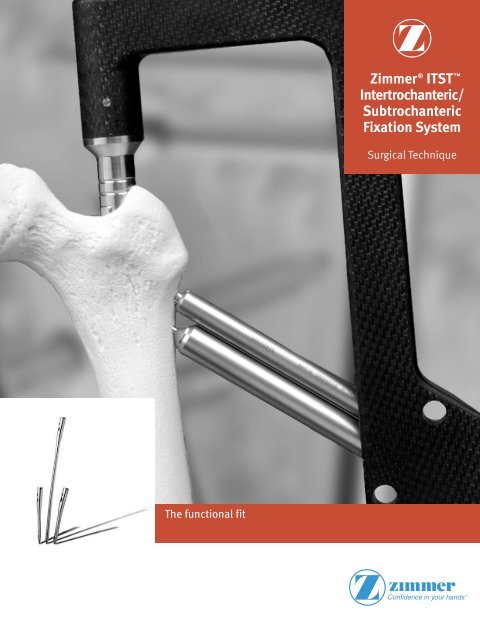
The functional fit<br />
Zimmer ® <strong>IT<strong>ST</strong></strong> <br />
Intertrochanteric/<br />
Subtrochanteric<br />
Fixation System<br />
Surgical Technique
<strong>IT<strong>ST</strong></strong> Intramedullary <strong>Nail</strong> Surgical Technique 1<br />
Surgical Technique<br />
for the <strong>IT<strong>ST</strong></strong><br />
Intramedullary<br />
<strong>Nail</strong> System<br />
Developed in conjunction with:<br />
Professor Ralf H. Gahr<br />
Chief Trauma Surgeon<br />
Trauma Center “St. Georg”<br />
Leipzig, Germany<br />
Richard F. Kyle, M.D.<br />
Chairman, Department of Orthopaedics<br />
Hennepin County Medical Center<br />
Associate Professor<br />
Department of Orthopaedic Surgery<br />
University of Minnesota<br />
Minneapolis, Minnesota<br />
Robert A. Winquist, M.D.<br />
Clinical Professor<br />
University of Washington<br />
Orthopaedic Surgeon<br />
Swedish Hospital and Medical Center<br />
Seattle, Washington<br />
Table of Contents<br />
Indications 2<br />
Contraindications 2<br />
Surgical Technique 3<br />
Preoperative Planning 3<br />
Patient Positioning 3<br />
Reduction 3<br />
Incision and Exposure 3<br />
Creating the Entry Portal 4<br />
Guide Wire Placement and Reaming 5<br />
<strong>Nail</strong> Assembly and Insertion 8<br />
Screw Options 11<br />
Lag Screw Positioning 11<br />
Lag Screw Preparation 12<br />
Lag Screw Insertion with <strong>IT<strong>ST</strong></strong> Compression Device 15<br />
Standard Lag Screw Insertion (optional) 16<br />
Anti-Rotation Screw Insertion 17<br />
Distal Screw Fixation –<br />
180mm/Short <strong>Nail</strong>s 18<br />
Distal Screw Fixation –<br />
Long <strong>Nail</strong>s Freehand Technique 20<br />
Completion 22<br />
Closure and Postoperative Care 24<br />
Extraction 24<br />
Implant and Instrument Case Options 25
2<br />
<strong>IT<strong>ST</strong></strong> Intramedullary <strong>Nail</strong> Surgical Technique<br />
The <strong>IT<strong>ST</strong></strong> Intramedullary <strong>Nail</strong> System<br />
is designed to treat unstable,<br />
comminuted, proximal fractures<br />
of the femur, specifically, the<br />
Intertrochanteric and Subtrochanteric<br />
regions, thereby combining many of<br />
the features of an intramedullary nail<br />
and hip screw system. The implant<br />
supports the anatomic reduction and<br />
internal fixation of the femoral head<br />
and neck and provides anti-rotational<br />
stability for many difficult fracture<br />
situations.<br />
The <strong>IT<strong>ST</strong></strong> Intramedullary <strong>Nail</strong> System<br />
features a sliding or non-sliding Lag<br />
Screw, to help allow for neck fracture<br />
settlement, while preventing fragment<br />
impaction. The system includes the<br />
options for dynamic and static distal<br />
locking.<br />
Manufactured from high strength<br />
stainless steel alloy (22-13-5), the<br />
<strong>IT<strong>ST</strong></strong> intramedullary nail implants<br />
are available in a wide range of<br />
diameters, as well as short and long<br />
lengths to accommodate total joint<br />
prostheses. The <strong>IT<strong>ST</strong></strong> Lag Screw has<br />
a 130° neck-shaft angle, which is the<br />
angle that most closely resembles the<br />
majority of femoral neck angles. In<br />
cases where appropriate, a 6.5mm<br />
Anti-Rotation Screw is available for<br />
use in combination with the 11mm<br />
Lag Screw to help stabilize fracture<br />
fragments.<br />
Indications<br />
The <strong>IT<strong>ST</strong></strong> Intramedullary <strong>Nail</strong> is indicated<br />
for use in a variety of femoral fractures,<br />
such as:<br />
• Subtrochanteric Fractures<br />
• Intertrochanteric Fractures<br />
• Comminuted Fractures<br />
• Segmental Fractures<br />
• Fractures with Bone Loss<br />
• Proximal and Distal Fractures<br />
• Nonunions<br />
Note: The surgeon should be<br />
aware that the use of the system<br />
in osteoporotic bone, or improper<br />
placement of the nail could increase<br />
the risk of failure or cut out of the<br />
implant.<br />
Contraindications<br />
Contraindications include:<br />
• Femoral fractures involving the knee<br />
joint<br />
• A medullary canal obliterated by a<br />
previous fracture or tumor<br />
• Femoral shaft having grossly<br />
abnormal, excessive bow (i.e.,<br />
curvature deformity)<br />
The implant is contraindicated for use<br />
in medial neck fractures. This implant<br />
may not provide the required/desired<br />
stability when used to treat some<br />
medial neck fractures.<br />
Overt systemic infection is an absolute<br />
contraindication. For patients that<br />
exhibit any of the following, systemic<br />
infection must be ruled out to minimize<br />
the potential hematogenous spread to<br />
the implant site:<br />
• Fever and/or local inflammation signs<br />
• Rapid joint destruction or bone<br />
absorption apparent on roentgenograms<br />
• Elevation of sedimentation rate<br />
unexplained by other diseases<br />
• Elevation of White Blood Cells (WBC)<br />
and/or marked shift in WBC differential<br />
Use of this device is contraindicated<br />
in patients with active infection at<br />
sites such as the genitourinary tract,<br />
pulmonary system, skin, or other<br />
sites because hematogenous spread<br />
may occur. The foci of infection must<br />
be treated and the infection resolved<br />
prior to surgery. Routine prophylactic<br />
antibiotic treatment immediately<br />
before, during, and after surgery may<br />
be especially useful for these patients. *<br />
* Nelson, J.P., et. al., Prophylactic Antimicrobial Coverage in<br />
Arthroplasty Patients. J Bone Joint Surg. 72A(1): 1, 1990
<strong>IT<strong>ST</strong></strong> Intramedullary <strong>Nail</strong> Surgical Technique 3<br />
Surgical Technique<br />
Preoperative Planning<br />
The <strong>IT<strong>ST</strong></strong> Femoral Fixation System<br />
implants are designed to place the Lag<br />
Screw at 130°, with 15° of anteversion<br />
on the long nails, to accommodate<br />
the most common anatomic femoral<br />
neck angle, while minimizing inventory<br />
requirements. A/P and lateral C-arm<br />
images should be obtained prior to<br />
the surgical procedure. The suitability<br />
of this implant for the patient should<br />
be determined prior to surgery by<br />
templating on the X-ray of the affected<br />
femur. An A/P preoperative X-ray<br />
should be taken of the contralateral<br />
hip or of the affected limb once an<br />
anatomic reduction has been achieved.<br />
X-rays taken at a 36-inch distance from<br />
the source result in 10-15 percent<br />
magnification of the bone. An Ossimeter,<br />
which takes this magnification into<br />
account, should be used to help<br />
determine the actual nail length and<br />
diameter to be used. The angle of the<br />
intersection of the femoral shaft axis and<br />
femoral neck axis should be observed.<br />
The <strong>IT<strong>ST</strong></strong> Templates reflect a 15 percent<br />
magnification of actual size.<br />
Patient Positioning<br />
After anesthesia has been administered,<br />
the patient should be placed in either<br />
the supine or lateral decubitus position<br />
on the table. The sacral rest and<br />
perineal post should be well padded.<br />
In multiple trauma patients, the supine<br />
position may be used for easier access<br />
to the patient’s airway, as well as to<br />
facilitate the treatment of other injuries.<br />
The supine position also facilitates<br />
fracture reduction and rotational<br />
alignment of the femur.<br />
In order to assist in Lag Screw and<br />
Anti-Rotation Screw placement, it is<br />
essential to obtain excellent quality A/P<br />
and lateral images of the entire femoral<br />
head and neck prior to beginning the<br />
surgery, regardless of which patient<br />
position is used.<br />
The use of C-arm or other X-ray imaging<br />
is required. The image intensifier, or Carm,<br />
should be sterile-draped and may<br />
be positioned from the contralateral<br />
side of the operating table. Confirm<br />
visualization of the hip as well as the<br />
shaft of the femur using C-arm before<br />
prepping and draping.<br />
Reduction<br />
It is critical to reduce the fracture before<br />
beginning the surgical procedure. An<br />
anatomic reduction or a slight valgus<br />
reduction of the femoral head and<br />
neck, should be seen in the A/P film.<br />
Occasionally, a slight sag of the fracture<br />
may be seen on the lateral view. This<br />
should be taken into consideration<br />
during the surgical procedure. This is<br />
most important for consideration of the<br />
starting point of the Steinmann Pins or<br />
cannulated awl into the Femoral head.<br />
Incision and Exposure<br />
Begin the skin incision 1 cm proximal<br />
to the tip of the greater trochanter,<br />
and extend it proximally for about<br />
5 cm in a longitudinal direction.<br />
Continue the incision down through<br />
the subcutaneous tissues and split the<br />
fascia lata.
4<br />
<strong>IT<strong>ST</strong></strong> Intramedullary <strong>Nail</strong> Surgical Technique<br />
Creating the Entry Portal<br />
Place the cannulated awl at the<br />
selected starting point (Fig. 1) and<br />
confirm its position in both the A/P<br />
and lateral planes on c-arm. Advance<br />
the cannulated awl through the greater<br />
trochanter to the lesser trochanter<br />
location.<br />
Fig. 1<br />
Creating the Entry Portal<br />
Optional Technique<br />
Locating the correct entry portal in the<br />
femur is extremely important. The<br />
insertion site for the nail is usually<br />
located at the tip of the greater<br />
trochanter. Place the 3.2mm Threaded<br />
Guide Pin at the selected starting point,<br />
and confirm its position in both the<br />
A/P and Lateral planes on C-arm.<br />
Check the position with the C-arm.<br />
Advance the pin down into the<br />
medullary canal approximately 4-5cm.<br />
Confirm the position of the pin<br />
using the C-arm with A/P and lateral<br />
views (Fig. 2). The Center Bushing and<br />
cannula may be used to minimize<br />
soft tissue disruption (Fig. 3). Place<br />
the Centering Bushing over the<br />
3.2mm Threaded Guide Pin to the<br />
tip of the greater trochanter. Remove<br />
the Centering Bushing, keeping<br />
the cannula in place at the greater<br />
trochanter. Place the 8mm Trochanteric<br />
Reamer over the guide pin and ream<br />
the trochanteric region to open the<br />
medullary canal (Fig. 4). Remove the<br />
Reamer and Threaded Guide Pin.<br />
Fig. 2<br />
3.2mm Threaded<br />
Guide Pin<br />
Fig. 3<br />
Fig. 4<br />
Percutaneous<br />
Trochanteric<br />
Reamer<br />
Cannula
<strong>IT<strong>ST</strong></strong> Intramedullary <strong>Nail</strong> Surgical Technique 5<br />
Guide Wire Placement<br />
On the back table, attach the 3.0mm<br />
Bulb-tipped Guide Wire to the Wire Grip<br />
T-Handle, and tighten (Fig. 5). The tip<br />
of the Guide Wire may be bent to<br />
approximately 45°, to facilitate fracture<br />
reduction. Note: If using a cannulated<br />
awl, the 3.0mm Bulb-Tipped Guide<br />
Wire may be passed through the<br />
cannulated awl without the 45° bend<br />
(Fig. 6). Insert the Guide Wire through<br />
the entry hole and manipulate it down<br />
the proximal femur across the fracture<br />
site. At the fracture site, manipulate the<br />
Guide Wire under C-arm control (Fig. 7)<br />
across the fracture site. An alternative<br />
technique is to reduce the fracture<br />
using the Reduction Instruments shown<br />
in figure 8. Once in the distal canal,<br />
pass the wire to the distal epiphyseal<br />
scar. If reduction of the abducted and<br />
flexed hip is difficult, place pressure on<br />
the proximal fragment, either with the<br />
hand or directly with a reduction rod<br />
or other instrument.<br />
Fig. 5<br />
Wire Grip<br />
T-Handle<br />
Bulb-tipped<br />
Guide Wire<br />
Fig. 6<br />
Fig. 7<br />
Wire Grip<br />
T-Handle<br />
Fig. 8 Reduction Instruments<br />
Reduction Finger<br />
Balled Spiked Pusher<br />
Bone Hook
6<br />
<strong>IT<strong>ST</strong></strong> Intramedullary <strong>Nail</strong> Surgical Technique<br />
Measure<br />
Determine the proper nail length by<br />
placing a second guide wire of equal<br />
length at the greater trochanter.<br />
The length of the wire that is not<br />
overlapping is the correct length.<br />
Optional <strong>Nail</strong> Measurement<br />
Connect the 2 piece <strong>Nail</strong> Length Gauge.<br />
Slide the gauge over the Guide Wire<br />
and measure (Fig. 9).<br />
Fig. 9<br />
Reaming<br />
The <strong>IT<strong>ST</strong></strong> Cannula can be inserted into<br />
the incision to protect the soft tissue.<br />
Thread the Centering Bushing into the<br />
Cannula and place the Cannula firmly<br />
against the bone. Remove Centering<br />
Bushing. Ream the femoral canal<br />
sequentially in 0.5mm increments<br />
using the Pressure Sentinel ®<br />
Intramedullary Reaming System<br />
(Fig. 10). Ream until cortical chatter is<br />
experienced. Based on bone quality,<br />
nail diameter is 1-2mm less than the<br />
last reamer used.<br />
Fig. 10<br />
Pressure Sentinel<br />
Reamer
<strong>IT<strong>ST</strong></strong> Intramedullary <strong>Nail</strong> Surgical Technique 7<br />
Over-reaming the canal by one or two<br />
millimeters may facilitate preparation of<br />
the bone to accommodate the implant.<br />
The trochanteric region should be<br />
reamed to 17mm in diameter in hard<br />
bone to accommodate the implant,<br />
using the Trochanteric Reamer (Fig. 11).<br />
Use caution in advancing the<br />
Trochanteric Reamer. An alternative to<br />
reaming with the trochanteric reamer<br />
is to sequentially ream with a Pressure<br />
Sentinel Intramedullary Reamer to<br />
desired diameter.<br />
Ream to the level of the lesser trochanter,<br />
to accommodate the implant by<br />
advancing the reamer into the proximal<br />
canal opening until the reamer flutes<br />
are sunk to the level of the lesser<br />
trochanter (Fig. 12). Confirm position<br />
using the C-arm. Replace the Bulb-Tipped<br />
Guide Wire with the Smooth Guide Wire<br />
through the Exchange Tube (Fig. 13).<br />
Note: If using a new 3.0mm Ball-Tip<br />
Guide Wire that DOES have a goldcoated<br />
end [Part numbers <strong>00</strong>-2255-<br />
<strong>00</strong>8-01 or 47-2255-<strong>00</strong>8-11 (sterile)]:<br />
The Ball-Tip Guide Wire can remain in<br />
place. It is not necessary to exchange<br />
the Ball-Tip Guide Wire for a Smooth<br />
Guide Wire. The new Ball-Tip Guide<br />
Wire with a gold-coated end can be<br />
pulled through all <strong>IT<strong>ST</strong></strong> <strong>Nail</strong> diameters,<br />
as well as mating instrumentation.<br />
The ball-tip will still be able to capture<br />
Pressure Sentinel reamer heads, if<br />
necessary.<br />
Note: Reaming amounts will depend<br />
on the quality of the bone present,<br />
the minimum diameter of the femoral<br />
shaft, and the amount of femoral<br />
curvature present.<br />
Trochanteric<br />
Reamer<br />
Fig. 11<br />
Exchange Tube<br />
(optional)<br />
Fig. 13<br />
Fig. 12
8<br />
<strong>IT<strong>ST</strong></strong> Intramedullary <strong>Nail</strong> Surgical Technique<br />
<strong>Nail</strong> Assembly<br />
Select the appropriate size <strong>IT<strong>ST</strong></strong><br />
Femoral <strong>Nail</strong>.<br />
Slide the <strong>IT<strong>ST</strong></strong> Locking Bolt through the<br />
barrel in the <strong>IT<strong>ST</strong></strong> Proximal Targeting<br />
Guide (Fig. 14). Approximate the nail<br />
to the external “keys” on the barrel of<br />
the <strong>IT<strong>ST</strong></strong> Proximal Targeting Guide.<br />
Note: The Guide is universal and it<br />
is critical that the nail be properly<br />
aligned with the Guide for a Left or<br />
Right implant. Line up the keys of the<br />
Guide with the keyways of the nail so<br />
that they fit snugly (Fig. 15).<br />
Place the T-Handled Locking Bolt<br />
Inserter into the guide barrel (Fig. 16).<br />
Toggle and rotate the Inserter slightly<br />
until it seats into the teeth of the<br />
Locking Bolt. The etched arrow at<br />
the proximal rim of the nail should be<br />
exactly aligned with the arrow on the<br />
distal rim of the Targeting Guide (Fig.<br />
17). Using downward pressure on<br />
the Locking Bolt Inserter, thread the<br />
Locking Bolt into the threads of the<br />
proximal end of the nail until secured.<br />
Completely tighten.<br />
Fig. 16<br />
Locking Bolt<br />
Inserter<br />
Proximal<br />
Targeting Guide<br />
Fig. 14<br />
Locking Bolt<br />
Key and Keyway<br />
Correct Alignment:<br />
arrow to arrow<br />
Fig. 17<br />
Fig. 15
<strong>IT<strong>ST</strong></strong> Intramedullary <strong>Nail</strong> Surgical Technique 9<br />
<strong>Nail</strong> Insertion<br />
Note: Prior to inserting the implant,<br />
insert the two sets of Drill and Screw<br />
Bushings into the appropriate holes<br />
in the Targeting Guide. Slide a drill or<br />
guide pin through the Bushings, and<br />
through the screw holes in the implant<br />
to assess correct instrument assembly<br />
(Fig. 18).<br />
<strong>Nail</strong> may be inserted by hand. If<br />
insertion can not be achieved by hand,<br />
please move to optional steps on page<br />
9. Insert nail (assembled with targeting<br />
guide) into the femoral canal.<br />
Fig. 18<br />
Guide Pin<br />
Lag Screw<br />
Bushing<br />
Optional <strong>Nail</strong> Insertion<br />
Attach the Driver Extension (Fig. 19) to<br />
the Targeting Guide (Fig. 20) by placing<br />
it into the Guide and sliding the Driver<br />
Extension Bolt down through the<br />
Driver Extension and into the Locking<br />
Bolt (Fig. 21). The Driver Extension is<br />
designed to be slightly off-axis from<br />
the Guide to assist the surgeon in<br />
impacting the implant away from the<br />
soft tissues. The Driver Extension<br />
attaches to the Locking Bolt by seating<br />
the teeth as done with Locking Bolt<br />
Inserter. Attach the Driver Extension to<br />
the threads of the Locking Bolt in the<br />
<strong>IT<strong>ST</strong></strong> Proximal Targeting Guide (Fig. 22).<br />
Tighten using the Pin Wrench to prevent<br />
disengagement.<br />
Fig. 19<br />
Fig. 20<br />
Driver Extension<br />
Fig. 21<br />
Fig. 22<br />
Driver Extension Bolt
10<br />
<strong>IT<strong>ST</strong></strong> Intramedullary <strong>Nail</strong> Surgical Technique<br />
Attach the Small or Long Threaded<br />
Driver to the Driver Extension (Fig.<br />
23). This may be placed in-line or<br />
offset from the nail axis. Insert the<br />
nail into the canal using a series of<br />
gentle impactions, if necessary, on the<br />
Threaded Driver until the nail is seated<br />
at the desired depth (Fig. 24).<br />
Note: Do not impact directly on the<br />
<strong>IT<strong>ST</strong></strong> Proximal Targeting Guide.<br />
Fig. 23<br />
Fig. 24<br />
Small or Long<br />
Threaded Driver<br />
Mallet<br />
Top of the Proximal Targeting Guide<br />
Monitoring Insertion<br />
Monitor the progression of the nail<br />
down the canal using C-arm. A<br />
percutaneous 3.2mm Threaded Guide<br />
Pin may be placed along the anterior<br />
axis of the femoral neck to mark the<br />
correct anteversion (Fig. 25).<br />
Align the Targeting Guide parallel to<br />
the percutaneous pin to assure that<br />
accurate implant anteversion has been<br />
achieved. Check the final position<br />
of the implant using C-arm. If the<br />
nail fails to progress easily down the<br />
canal, remove it, and use a smaller<br />
nail, or over-ream the canal in 0.5mm<br />
increments until the implant passes<br />
more easily down the femoral canal.<br />
Fig. 25<br />
3.2mm Threaded<br />
Guide Pin
<strong>IT<strong>ST</strong></strong> Intramedullary <strong>Nail</strong> Surgical Technique 11<br />
Screw Options<br />
The <strong>IT<strong>ST</strong></strong> <strong>Nail</strong> accommodates both an<br />
11mm Lag Screw and a 6.5mm<br />
Anti-Rotation Screw. The Anti-Rotation<br />
Screw may be utilized in the case of<br />
certain fractures, where the bone stock<br />
and femoral neck/head bone stock is<br />
able to accommodate it. If only one screw<br />
is used, it must be the 11mm Lag Screw.<br />
Note: The 6.5mm Anti-Rotation Screw<br />
may be used to enhance fracture<br />
stability if the femoral neck is able to<br />
accommodate it; however, it should<br />
not be used if there is any concern that<br />
the femoral head or neck bone will not<br />
accommodate it. Failure to appropriately<br />
consider femoral head/neck bone mass<br />
and quality could result in implant<br />
cut-out.<br />
Lag Screw Positioning<br />
The projected path of the Lag Screw<br />
into the Femoral Head should be<br />
assessed using the C-arm (Fig. 26).<br />
This may be verified using the Screw<br />
Position Outrigger and the 3.2mm<br />
Threaded Guide Pin. Assemble the<br />
Outrigger into the <strong>IT<strong>ST</strong></strong> Proximal<br />
Targeting Guide and place a Threaded<br />
Guide Pin into the Anteversion<br />
Verification Hole in the proximal portion<br />
of the Proximal Targeting Guide (Fig. 27).<br />
Verify under C-arm that the Guide Pin<br />
appears in the center of the femoral<br />
neck in a superior/lateral view (Fig. 28).<br />
This will help prevent any parallax error.<br />
The outer aspect of the windowed arm<br />
of the Outrigger, which lies directly<br />
over the femoral neck, represents the<br />
superior and inferior position of the Lag<br />
and Anti-Rotation Screws (Fig. 29).<br />
If the nail anteversion requires<br />
adjustment, move the nail up or down<br />
the canal by gently impacting the<br />
Threaded Driver until the correct depth<br />
is achieved. Check the position of the<br />
nail with the C-arm. Adjusting nail<br />
depth may be useful in accommodating<br />
various femoral neck anatomies.<br />
Note: If the C-arm is off axis, the<br />
alignment of the Outrigger may not<br />
accurately predict the position of Lag<br />
and Anti-Rotation Screws. In the event<br />
this occurs, adjust the position of the<br />
C-arm until it is on axis.<br />
Fig. 26<br />
Fig. 28<br />
Lag Screw<br />
Projected Path<br />
Fig. 27<br />
Inferior Lag<br />
Screw Position<br />
Fig. 29<br />
Superior Anti-rotation<br />
Screw Position
12<br />
<strong>IT<strong>ST</strong></strong> Intramedullary <strong>Nail</strong> Surgical Technique<br />
Lag Screw Preparation<br />
Note: The 6.5mm Anti-Rotation Screw<br />
may be used to enhance fracture<br />
stability if the femoral neck is able to<br />
accommodate it.<br />
Remove the 3.2mm Guide Wire.<br />
Assemble the Lag Screw Pin Bushing<br />
and Lag Screw Bushing together and<br />
place the assembly into the inferior<br />
screw hole in the Targeting Guide (Fig.<br />
30). Assemble the 3.2mm Guide Pin<br />
Bushing, the 5.0mm Drill Bushing and<br />
the 8.0mm Screw Bushing and insert<br />
the assembly into the superior screw<br />
hole in the Targeting Guide (Fig. 31).<br />
Make small incisions in the soft tissue<br />
and through the iliotibial band, down<br />
to the lateral cortex of the femur. Be<br />
certain that the bushings are firmly<br />
seated on the bone. Do not force the<br />
bushings or impact.<br />
Insert a 3.2mm Threaded Guide Pin into<br />
the inferior set of bushings. Drill<br />
the Guide Pin to the level of the<br />
subchondral bone of the femoral head,<br />
without penetrating the femoral cortex<br />
(Fig. 32). Insert a Guide Pin into the<br />
superior set of bushings. The Screw<br />
Inserter Adapter may be used with this<br />
Guide Pin to prevent impingement on<br />
the adjacent Guide Pin during insertion<br />
(Fig. 33). Drill the Guide Pin to the level<br />
of the subchondral bone of the femoral<br />
head, without penetrating the femoral<br />
cortex. Assess the position of the Guide<br />
Pins using C-arm in the A/P and lateral<br />
planes.<br />
Note: Ideally each Guide Pin should<br />
be situated well inside the femoral<br />
neck to allow adequate room for screw<br />
placement without contacting the<br />
cortical wall. If there is not sufficient<br />
cortical wall surrounding the Guide<br />
Pins on examination with the C-arm,<br />
the nail may be repositioned and<br />
implanted using only the Lag Screw.<br />
Fig. 30<br />
Subchondral<br />
Bone<br />
Fig. 32<br />
Lag Screw<br />
Bushing<br />
Fig. 31<br />
3.2mm Threaded<br />
Guide Pin<br />
Fig. 33<br />
8.0mm Screw Bushing<br />
5.0mm Drill Bushing<br />
3.2mm Threaded<br />
Guide Pin Bushing<br />
Screw Inserter<br />
Adaptor
<strong>IT<strong>ST</strong></strong> Intramedullary <strong>Nail</strong> Surgical Technique 13<br />
Remove the Lag Screw Pin Bushing.<br />
Slide the Cannulated Depth Gauge<br />
over the lag screw Guide Pin, i.e. the<br />
inferior of the two guide pins, until the<br />
gauge contacts the lateral aspect of the<br />
femur (Fig. 34). Assess that the Gauge<br />
is seated against the bone using the<br />
C-arm. Read and record the length of<br />
the guide pin from the calibrated depth<br />
gauge.<br />
Note: This measurement designates<br />
the correct length of the Lag Screw to<br />
be implanted (Fig. 35).<br />
Slide the Stop Assembly onto the <strong>IT<strong>ST</strong></strong><br />
Lag Screw Reamer, keeping the gold<br />
portion of the Stop Assembly toward<br />
the cutting end of the reamer (Fig. 36).<br />
Move the Stop Assembly along the<br />
incremented lengths listed on the<br />
reamer. Align the threaded end of the<br />
Stop Assembly with the notch denoting<br />
the appropriate length.<br />
Gold cutting<br />
edge of reamer<br />
Fig. 34<br />
Fig. 35<br />
Cannulated<br />
Depth Gauge<br />
Gold Knob Gold portion of Stop<br />
Assembly pointed toward<br />
gold cutting edge of reamer<br />
Stop Assembly<br />
Fig. 36<br />
Lag Screw Reamer<br />
Threaded<br />
Guide Pin<br />
Cannulated<br />
Depth Gauge
14<br />
<strong>IT<strong>ST</strong></strong> Intramedullary <strong>Nail</strong> Surgical Technique<br />
When the Stop Assembly is fully seated,<br />
the arrow on the Stop Assembly will<br />
indicate the appropriate depth level.<br />
This “length” corresponds to the<br />
measurement obtained from the guide<br />
pin (Fig. 37).<br />
Place the <strong>IT<strong>ST</strong></strong> Lag Screw Reamer over<br />
the Guide Pin and seat it against the<br />
femoral cortex. Under power, advance<br />
the reamer until the Stop Assembly<br />
stops against the Lag Screw Bushing<br />
(Fig. 38). Monitor progress of the reamer<br />
using the C-arm. Remove the reamer.<br />
Assemble the Lag Screw Tap by locking<br />
the Stop Assembly at the level of the<br />
appropriate measurement, in the same<br />
fashion as the Lag Screw Reamer. Place<br />
the Lag Screw Tap over the Guide Pin<br />
and through the Lag Screw Bushing.<br />
Advance the tap until the Stop Assembly<br />
stops against the collar of the Lag<br />
Screw Bushing (Fig. 39). Confirm Tap<br />
position with the C-arm.<br />
Stop Assembly<br />
Gold<br />
Fig. 37<br />
Lag Screw<br />
Bushing<br />
Fig. 38<br />
Fig. 39<br />
Lag Screw<br />
Reamer<br />
Stop Assembly is flush<br />
against the Lag Screw Bushing<br />
Lag Screw Tap<br />
T-Handle
<strong>IT<strong>ST</strong></strong> Intramedullary <strong>Nail</strong> Surgical Technique 15<br />
Lag Screw Insertion With <strong>IT<strong>ST</strong></strong><br />
Compression Device<br />
If not using the <strong>IT<strong>ST</strong></strong> Compression<br />
Device, proceed to page 16.<br />
Thread the Compressor onto the Lag<br />
Screw Compression Device T-Handle.<br />
Insert Compression Retainer through<br />
the Lag Screw Compression Device<br />
T-Handle (Fig. 40) and thread into<br />
the appropriate Lag Screw until it is<br />
securely fastened to the Lag Screw<br />
Compression Device T-Handle. Pass<br />
the Lag Screw Compression Device<br />
assembly through the Lag Screw<br />
Bushing and over the Guide Pin (Fig.<br />
41). Thread Lag Screw to within 5mm<br />
of the subchondral bone, monitoring<br />
the Lag Screw advancement with the<br />
C-arm.<br />
If planning to use a <strong>Nail</strong> Cap which<br />
prevents rotation or limits sliding,<br />
rotate the Lag Screw Compression<br />
Device T-Handle (Fig. 42) such that one<br />
of the four etched lines is in line with<br />
the etched line on the Proximal<br />
Targeting Guide.<br />
After inserting the Lag Screw to the<br />
appropriate depth, confirm Lag Screw<br />
position using the C-arm. To begin<br />
compression of the femoral neck, begin<br />
advancing the Compressor clockwise<br />
against the Lag Screw Bushing (Fig.<br />
43). The surgeon continues to advance<br />
the Compressor while monitoring<br />
femoral neck compression using the<br />
C-arm, until the desired fracture<br />
reduction is achieved.<br />
After reduction, unthread the<br />
Compression Retainer from the Lag<br />
Screw. After removing the Compression<br />
Retainer, the Lag Screw Compression<br />
Device Assembly can be removed.<br />
Remove the Superior Guide Pin and<br />
Bushings if used. If using <strong>IT<strong>ST</strong></strong> Global<br />
Long <strong>Nail</strong>, remove Targeting Guide<br />
using the Pin Wrench and Locking Bolt<br />
Fig. 40<br />
Lag Screw Compressor<br />
(Replacement Part <strong>00</strong>-2258-0<strong>97</strong>-01)<br />
Fig. 42<br />
Proximal Targeting<br />
Guide Indicator Line<br />
Rotate Clockwise<br />
Fig. 41<br />
Fig. 43<br />
Compression<br />
Device T-Handle<br />
Compression<br />
Retainer
16<br />
<strong>IT<strong>ST</strong></strong> Intramedullary <strong>Nail</strong> Surgical Technique<br />
Standard Lag Screw Insertion<br />
(Optional)<br />
Thread the Inserter Link (Fig. 44) into<br />
the Lag Screw until securely fastened.<br />
Slide the Lag Screw Inserter Shaft over<br />
the Inserter Link (Fig. 45).<br />
Fig. 44<br />
Fig. 45<br />
Fig. 46<br />
Lag Screw<br />
Inserter Shaft<br />
Insert this assembly over the Guide Pin.<br />
Thread the Lag Screw to within 5mm<br />
of the Subchondral bone. Rotate the<br />
Inserter Shaft (Fig. 46) and align one of<br />
the four etch lines on the Inserter Shaft<br />
with the indicator line on the Proximal<br />
Targeting Guide (Fig. 47). Check the Lag<br />
Screw position using the C-arm. Leave<br />
the Inserter Link attached to the Lag<br />
Screw (Fig. 48).<br />
Inserter Link<br />
Fig. 47<br />
Fig. 48<br />
Proximal Targeting<br />
Guide Indicator Line<br />
Inserter Shaft<br />
Etch Line<br />
Inserter Link
<strong>IT<strong>ST</strong></strong> Intramedullary <strong>Nail</strong> Surgical Technique 17<br />
Anti-Rotation Screw Insertion<br />
Remove the 3.2mm Pin Bushing. Slide<br />
the Cannulated Depth Gauge over the<br />
Guide Pin, until the Gauge contacts<br />
the lateral aspect of the femur. Confirm<br />
the position of the Depth Gauge using<br />
the C-arm. Read the depth of the guide<br />
pin from the Cannulated Depth Gauge.<br />
The Anti-Rotation Screw length should<br />
be 15mm to 20mm shorter than the<br />
depth gauge measurement. This will<br />
provide the proper screw placement to<br />
help minimize femoral neck cutout*<br />
(Fig. 49). Remove the Guide Pin. Under<br />
C-arm control, drill into the femur<br />
with the 5.0mm Drill until the correct<br />
calibration on the drill is level with the<br />
outer collar of the Drill Bushing.<br />
Remove the 5.0mm Drill Bushing and<br />
Drill. Insert the Anti-Rotation Screw<br />
using the 5.0mm T-Handle Screwdriver<br />
through the 8mm Screw Bushing and<br />
into the femoral head until seated.<br />
Placement of the screw should be<br />
monitored using the C-arm.<br />
* Baumgaertner, MR, et al., J Bone Joint Surg. AM.<br />
1996 Sep; 78(9):1447-1448<br />
Fig. 49
18<br />
<strong>IT<strong>ST</strong></strong> Intramedullary <strong>Nail</strong> Surgical Technique<br />
Distal Screw Fixation –<br />
180mm / Short <strong>Nail</strong>s<br />
With the Proximal Targeting Guide still<br />
in place, retighten the Locking Bolt if<br />
necessary. Assemble the appropriate<br />
Drill Bushing (see Table 1) into the<br />
8.0mm Screw Bushing, and place<br />
the nested bushings through one of<br />
the distal targeting holes in the <strong>IT<strong>ST</strong></strong><br />
Proximal Targeting Guide (Fig. 50).<br />
Make a small incision through the skin<br />
and fascia lata. Spread the soft tissue<br />
down to the bone. Advance the bushing<br />
until it contacts the lateral femoral<br />
cortex. Advance the appropriate size<br />
Drill through the bushings until both<br />
cortices of bone have been penetrated.<br />
Note: If using the Calibrated 3.7mm or<br />
5.0mm Drill, read calibrations from end<br />
of bushing to determine screw length.<br />
Table 1.<br />
<strong>IT<strong>ST</strong></strong> Global<br />
<strong>Nail</strong>s 180mm<br />
Diameter Distal Screw Drill Size<br />
10mm <strong>Nail</strong> 4.5mm Screw 3.7mm Drill<br />
11mm <strong>Nail</strong> 5.5mm Screw 5.0mm Drill<br />
12mm <strong>Nail</strong> 5.5mm Screw 5.0mm Drill<br />
13mm <strong>Nail</strong> 5.5mm Screw 5.0mm Drill<br />
14mm <strong>Nail</strong> 5.5mm Screw 5.0mm Drill<br />
15mm <strong>Nail</strong> 5.5mm Screw 5.0mm Drill<br />
<strong>IT<strong>ST</strong></strong> Global<br />
<strong>Nail</strong>s 3<strong>00</strong>-5<strong>00</strong>mm<br />
10mm <strong>Nail</strong> 4.5mm Screw 3.7mm Drill<br />
11mm <strong>Nail</strong> 5.5mm Screw 5.0mm Drill<br />
12mm <strong>Nail</strong> 5.5mm Screw 5.0mm Drill<br />
13mm <strong>Nail</strong> 5.5mm Screw 5.0mm Drill<br />
14mm <strong>Nail</strong> 5.5mm Screw 5.0mm Drill<br />
Fig. 50
<strong>IT<strong>ST</strong></strong> Intramedullary <strong>Nail</strong> Surgical Technique 19<br />
Remove the Drill and Drill Bushing,<br />
and insert the <strong>IT<strong>ST</strong></strong> Screw Depth Gauge<br />
through the 8.0mm Screw Bushing until<br />
the gauge captures the far cortex of<br />
bone (Fig. 51, 52).<br />
Read the measurement for the screw<br />
from the end of the depth gauge.<br />
Note: Choose a screw length that is<br />
at least 2.5mm longer than the depth<br />
measured, to ensure that bicortical<br />
screw fixation is attained.<br />
If the bone quality is good, it may be<br />
necessary to tap the channel using the<br />
4.5mm Tap (Fig. 53).<br />
Fig. 51<br />
Place the appropriate length Cortical<br />
Screw onto the 3.5mm T-Handle Hex<br />
Screwdriver and insert the screw into<br />
the bone through the 8.0mm Screw<br />
Bushing, until it is flush against the<br />
lateral cortex of the femur (Fig. 54).<br />
Confirm the position of the screw in the<br />
A/P and lateral views with the C-arm.<br />
Place the second distal locking screw in<br />
the same fashion as the first.<br />
Depth Gauge<br />
Fig. 53<br />
Tap<br />
Tip of<br />
Depth<br />
Gauge<br />
Fig. 52<br />
Fig. 54
20<br />
<strong>IT<strong>ST</strong></strong> Intramedullary <strong>Nail</strong> Surgical Technique<br />
Distal Screw Fixation – Long<br />
<strong>Nail</strong>s – Freehand Technique<br />
The distal locking screws may be<br />
inserted with a freehand technique<br />
using the Freehand Targeting Device<br />
(Fig. 55). Insert a 3.7mm Drill (Color<br />
Code: Blue) for a 4.5mm screw, or<br />
insert a 5.0mm Drill (Color Code: Green)<br />
for 5.5mm screw into the Freehand<br />
Targeting Device. Finger tighten the set<br />
screw.<br />
Choose the appropriate locking hole<br />
based on the need for dynamization.<br />
The superior locking hole on the <strong>IT<strong>ST</strong></strong><br />
<strong>Nail</strong> is used for static locking, while the<br />
distal locking hole is used for dynamic<br />
locking. If static locking is preferred,<br />
but there is a potential need for later<br />
dynamization, insert screws in both<br />
locking holes. The locking screw in the<br />
static hole can then be removed to<br />
achieve later dynamization.<br />
For success with this technique, proper<br />
placement of the lateral X-ray beam<br />
is critical. Position the C-arm so that<br />
the locking hole of the nail appears<br />
perfectly round on the monitor (Fig. 56<br />
& 57).<br />
When this is achieved, bring the tip<br />
of the 3.7mm Drill to the skin and use<br />
the C-arm to center it over the hole.<br />
Make a lateral stab wound opposite the<br />
appropriate locking hole, and dissect<br />
down to the bone. Bring the tip of the<br />
3.7mm Drill to the bone and center it<br />
over the locking hole using the C-arm.<br />
Align the 3.7mm Drill with the axis of<br />
the X-ray beam. Drive the 3.7mm Drill<br />
into the bone and across the hole in<br />
the nail in line with the lateral X-ray<br />
beam (Fig. 58). Before drilling through<br />
the medial cortex, check the A/P and<br />
lateral C-arm image to assure that<br />
the drill is in the hole in the nail. Drill<br />
through the medial cortex (Fig. 59 & 60).<br />
Fig. 55<br />
Fig. 57<br />
Trocar Drill<br />
Freehand<br />
Targeting Device<br />
Incorrect<br />
Correct<br />
Fig. 56<br />
Fig. 58<br />
Incorrect<br />
Correct<br />
Bone Drill
<strong>IT<strong>ST</strong></strong> Intramedullary <strong>Nail</strong> Surgical Technique 21<br />
Remove the Drill and insert the Distal<br />
Screw Depth Gauge (Fig. 61). The<br />
length of the screw is determined by<br />
reading it directly off the Distal Screw<br />
Depth Gauge.<br />
Note: Select an appropriate length<br />
screw to ensure adequate engagement<br />
of the medial cortex.<br />
Insert the appropriate size M/DN ®<br />
Screw using the Distal Screwdriver<br />
(Fig. 62).<br />
If desired, insert the second screw<br />
in the second locking hole of the nail<br />
in an identical manner. Check the<br />
position of both screws with the C-arm<br />
in the A/P and lateral planes (Fig. 63).<br />
Bushings are available that can be<br />
used with the Freehand Targeting<br />
Device. A separate radiolucent Bushing<br />
Insert is available to aid in targeting.<br />
Fig. 62<br />
Distal<br />
Screwdriver<br />
Bi-cortical<br />
Fixation<br />
Fig. 59<br />
Fig. 61<br />
Lateral Cortex<br />
Distal Screw<br />
Depth Gauge<br />
Fig. 60<br />
Fig. 63<br />
Medial Cortex<br />
Example of<br />
Static Locking
22<br />
<strong>IT<strong>ST</strong></strong> Intramedullary <strong>Nail</strong> Surgical Technique<br />
Completion<br />
Remove the <strong>IT<strong>ST</strong></strong> Proximal Targeting<br />
Guide and Driver Extension Bolt<br />
using the Pin Wrench or Socket Drive<br />
as shown. Remove the Locking Bolt<br />
using the Locking Bolt Extractor (Fig.<br />
64). Take care to leave the Lag Screw<br />
Inserter Link in place for final <strong>Nail</strong><br />
Cap seating.<br />
Insert the appropriate <strong>Nail</strong> Cap: Neutral<br />
<strong>Nail</strong> Cap (Fig. 65), Sliding <strong>Nail</strong> Cap (Fig.<br />
66), or Locking <strong>Nail</strong> Cap (Fig. 67) with<br />
the <strong>Nail</strong> Cap Inserter, or the One-Piece<br />
<strong>Nail</strong> Cap Inserter (Fig. 68, 69).<br />
Locking Bolt Extractor<br />
Fig. 64<br />
Fig. 65 Neutral Cap* (5mm shown)<br />
Fig. 66 Sliding Cap* (0mm shown)<br />
Fig. 67 Locking Cap* (15mm shown)<br />
* All <strong>Nail</strong> Caps are available in 0, 5, 10, 15, and<br />
20mm head sizes.
<strong>IT<strong>ST</strong></strong> Intramedullary <strong>Nail</strong> Surgical Technique 23<br />
Tighten until fully seated. If using a<br />
Sliding or Locking Cap, slide the Lag<br />
Screw Inserter Shaft over the Insert Link<br />
and into the Lag Screw (Fig. 68). Slowly<br />
rotate the Lag Screw Inserter and <strong>Nail</strong><br />
Cap Inserter until the <strong>Nail</strong> Cap flange<br />
can be felt seating into one of the four<br />
lag screw shaft grooves (Fig. 70). (See<br />
Fig. 71 for <strong>Nail</strong> Cap Inserter options.)<br />
Fig. 68<br />
One-Piece <strong>Nail</strong> Cap Inserter<br />
Fig. 69<br />
Lag Screw Inserter Shaft<br />
<strong>Nail</strong> Cap Inserter<br />
<strong>Nail</strong> Cap<br />
Fig. 70<br />
Fig. 71 <strong>Nail</strong> Cap Inserter Designs
24<br />
<strong>IT<strong>ST</strong></strong> Intramedullary <strong>Nail</strong> Surgical Technique<br />
Closure and Postoperative Care<br />
Close the proximal wound and apply a<br />
soft compression dressing.<br />
Early range of motion exercises of the<br />
knee and ankle are encouraged. Allow<br />
toe-touch weight bearing to progress<br />
to full weight bearing as fracture callus<br />
increases on the X-ray films, usually at<br />
six to eight weeks.<br />
Extraction<br />
In order to extract the nail, remove any<br />
existing distal screws with the 3.5mm<br />
T-Handle Hex Screwdriver. Remove<br />
the <strong>Nail</strong> Cap with the 5.0mm T-Handle<br />
Screwdriver. Make a small incision<br />
in the area of the existing proximal<br />
incision to expose the ends of the Lag<br />
Screw and Anti-Rotation Screw. Clear<br />
any bony ingrowth away from the Lag<br />
Screw hex, and thread the Retaining<br />
Shaft into the Lag Screw. Slide the<br />
Lag Screw Inserter into the Lag Screw,<br />
and tighten the Extraction Knob.<br />
Remove the lag screw, turning counter<br />
clockwise, with a slight backward<br />
pulling motion (Fig. 72). Once the Lag<br />
Screw has been removed, use the 5.0<br />
mm T-Handled Hexdriver to remove the<br />
Anti-Rotation Screw.<br />
Attach the Extractor Bolt into the nail<br />
(Fig. 73). Screw the Slaphammer onto<br />
the Extractor Bolt and remove the nail.<br />
Fig. 73<br />
Fig. 72<br />
Extractor Bolt<br />
Retaining Shaft
<strong>IT<strong>ST</strong></strong> Intramedullary <strong>Nail</strong> Surgical Technique 25<br />
Implant and Instrument Case Options<br />
Prod. No. Description Size<br />
<strong>00</strong>-2257-<strong>00</strong>0-07 <strong>IT<strong>ST</strong></strong> Asia Set<br />
(contains the following)<br />
<strong>00</strong>-2256-180-10 Univ L/R Fem <strong>IM</strong> <strong>Nail</strong> 10mmDX18cm<br />
<strong>00</strong>-2256-180-11 Univ L/R Fem <strong>IM</strong> <strong>Nail</strong> 11mmDX18cm<br />
<strong>00</strong>-2256-180-12 Univ L/R Fem <strong>IM</strong> <strong>Nail</strong> 12mmDX18cm<br />
<strong>00</strong>-2256-180-13 Univ L/R Fem <strong>IM</strong> <strong>Nail</strong> 13mmDX18cm<br />
<strong>00</strong>-2256-180-14 Univ L/R Fem <strong>IM</strong> <strong>Nail</strong> 14mmDX18cm<br />
<strong>00</strong>-2256-180-15 Univ L/R Fem <strong>IM</strong> <strong>Nail</strong> 15mmDX18cm<br />
<strong>00</strong>-2257-<strong>00</strong>0-05 <strong>IT<strong>ST</strong></strong> Global Short Set<br />
(contains the following)<br />
<strong>00</strong>-2257-180-10 Univ L/R Fem <strong>IM</strong> <strong>Nail</strong> 10mmDX18cm<br />
<strong>00</strong>-2257-180-11 Univ L/R Fem <strong>IM</strong> <strong>Nail</strong> 11mmDX18cm<br />
<strong>00</strong>-2257-180-12 Univ L/R Fem <strong>IM</strong> <strong>Nail</strong> 12mmDX18cm<br />
<strong>00</strong>-2257-180-13 Univ L/R Fem <strong>IM</strong> <strong>Nail</strong> 13mmDX18cm<br />
<strong>00</strong>-2257-180-14 Univ L/R Fem <strong>IM</strong> <strong>Nail</strong> 14mmDX18cm<br />
<strong>00</strong>-2257-180-15 Univ L/R Fem <strong>IM</strong> <strong>Nail</strong> 15mmDX18cm<br />
<strong>00</strong>-2257-<strong>00</strong>0-06 <strong>IT<strong>ST</strong></strong> Global Long Set<br />
(contains the following)<br />
<strong>00</strong>-2257-3<strong>00</strong>-<strong>00</strong> Left Fem <strong>IM</strong> <strong>Nail</strong> 10mmDX30cm<br />
<strong>00</strong>-2257-3<strong>00</strong>-01 Left Fem <strong>IM</strong> <strong>Nail</strong> 11mmDX30cm<br />
<strong>00</strong>-2257-3<strong>00</strong>-02 Left Fem <strong>IM</strong> <strong>Nail</strong> 12mmDX30cm<br />
<strong>00</strong>-2257-3<strong>00</strong>-03 Left Fem <strong>IM</strong> <strong>Nail</strong> 13mmDX30cm<br />
<strong>00</strong>-2257-3<strong>00</strong>-04 Left Fem <strong>IM</strong> <strong>Nail</strong> 14mmDX30cm<br />
<strong>00</strong>-2257-3<strong>00</strong>-10 Right Fem <strong>IM</strong> <strong>Nail</strong> 10mmDX30cm<br />
<strong>00</strong>-2257-3<strong>00</strong>-11 Right Fem <strong>IM</strong> <strong>Nail</strong> 11mmDX30cm<br />
<strong>00</strong>-2257-3<strong>00</strong>-12 Right Fem <strong>IM</strong> <strong>Nail</strong> 12mmDX30cm<br />
<strong>00</strong>-2257-3<strong>00</strong>-13 Right Fem <strong>IM</strong> <strong>Nail</strong> 13mmDX30cm<br />
<strong>00</strong>-2257-3<strong>00</strong>-14 Right Fem <strong>IM</strong> <strong>Nail</strong> 14mmDX30cm<br />
<strong>00</strong>-2257-320-<strong>00</strong> Left Fem <strong>IM</strong> <strong>Nail</strong> 10mmDX32cm<br />
<strong>00</strong>-2257-320-01 Left Fem <strong>IM</strong> <strong>Nail</strong> 11mmDX32cm<br />
<strong>00</strong>-2257-320-02 Left Fem <strong>IM</strong> <strong>Nail</strong> 12mmDX32cm<br />
<strong>00</strong>-2257-320-03 Left Fem <strong>IM</strong> <strong>Nail</strong> 13mmDX32cm<br />
<strong>00</strong>-2257-320-04 Left Fem <strong>IM</strong> <strong>Nail</strong> 14mmDX32cm<br />
<strong>00</strong>-2257-320-10 Right Fem <strong>IM</strong> <strong>Nail</strong> 10mmDX32cm<br />
<strong>00</strong>-2257-320-11 Right Fem <strong>IM</strong> <strong>Nail</strong> 11mmDX32cm<br />
<strong>00</strong>-2257-320-12 Right Fem <strong>IM</strong> <strong>Nail</strong> 12mmDX32cm<br />
<strong>00</strong>-2257-320-13 Right Fem <strong>IM</strong> <strong>Nail</strong> 13mmDX32cm<br />
<strong>00</strong>-2257-320-14 Right Fem <strong>IM</strong> <strong>Nail</strong> 14mmDX32cm<br />
<strong>00</strong>-2257-340-<strong>00</strong> Left Fem <strong>IM</strong> <strong>Nail</strong> 10mmDX34cm<br />
<strong>00</strong>-2257-340-01 Left Fem <strong>IM</strong> <strong>Nail</strong> 11mmDX34cm<br />
<strong>00</strong>-2257-340-02 Left Fem <strong>IM</strong> <strong>Nail</strong> 12mmDX34cm<br />
<strong>00</strong>-2257-340-03 Left Fem <strong>IM</strong> <strong>Nail</strong> 13mmDX34cm<br />
<strong>00</strong>-2257-340-04 Left Fem <strong>IM</strong> <strong>Nail</strong> 14mmDX34cm<br />
<strong>00</strong>-2257-340-10 Right Fem <strong>IM</strong> <strong>Nail</strong> 10mmDX34cm<br />
<strong>00</strong>-2257-340-11 Right Fem <strong>IM</strong> <strong>Nail</strong> 11mmDX34cm<br />
<strong>00</strong>-2257-340-12 Right Fem <strong>IM</strong> <strong>Nail</strong> 12mmDX34cm<br />
<strong>00</strong>-2257-340-13 Right Fem <strong>IM</strong> <strong>Nail</strong> 13mmDX34cm<br />
<strong>00</strong>-2257-340-14 Right Fem <strong>IM</strong> <strong>Nail</strong> 14mmDX34cm<br />
<strong>00</strong>-2257-360-<strong>00</strong> Left Fem <strong>IM</strong> <strong>Nail</strong> 10mmDX36cm<br />
<strong>00</strong>-2257-360-01 Left Fem <strong>IM</strong> <strong>Nail</strong> 11mmDX36cm<br />
<strong>00</strong>-2257-360-02 Left Fem <strong>IM</strong> <strong>Nail</strong> 12mmDX36cm<br />
<strong>00</strong>-2257-360-03 Left Fem <strong>IM</strong> <strong>Nail</strong> 13mmDX36cm<br />
<strong>00</strong>-2257-360-04 Left Fem <strong>IM</strong> <strong>Nail</strong> 14mmDX36cm<br />
<strong>00</strong>-2257-360-10 Right Fem <strong>IM</strong> <strong>Nail</strong> 10mmDX36cm<br />
<strong>00</strong>-2257-360-11 Right Fem <strong>IM</strong> <strong>Nail</strong> 11mmDX36cm<br />
<strong>00</strong>-2257-360-12 Right Fem <strong>IM</strong> <strong>Nail</strong> 12mmDX36cm<br />
<strong>00</strong>-2257-360-13 Right Fem <strong>IM</strong> <strong>Nail</strong> 13mmDX36cm<br />
<strong>00</strong>-2257-360-14 Right Fem <strong>IM</strong> <strong>Nail</strong> 14mmDX36cm<br />
<strong>00</strong>-2257-380-<strong>00</strong> Left Fem <strong>IM</strong> <strong>Nail</strong> 10mmDX38cm<br />
<strong>00</strong>-2257-380-01 Left Fem <strong>IM</strong> <strong>Nail</strong> 11mmDX38cm<br />
<strong>00</strong>-2257-380-02 Left Fem <strong>IM</strong> <strong>Nail</strong> 12mmDX38cm<br />
<strong>00</strong>-2257-380-03 Left Fem <strong>IM</strong> <strong>Nail</strong> 13mmDX38cm<br />
<strong>00</strong>-2257-380-04 Left Fem <strong>IM</strong> <strong>Nail</strong> 14mmDX38cm<br />
<strong>00</strong>-2257-380-10 Right Fem <strong>IM</strong> <strong>Nail</strong> 10mmDX38cm<br />
<strong>00</strong>-2257-380-11 Right Fem <strong>IM</strong> <strong>Nail</strong> 11mmDX38cm<br />
<strong>00</strong>-2257-380-12 Right Fem <strong>IM</strong> <strong>Nail</strong> 12mmDX38cm<br />
<strong>00</strong>-2257-380-13 Right Fem <strong>IM</strong> <strong>Nail</strong> 13mmDX38cm<br />
<strong>00</strong>-2257-380-14 Right Fem <strong>IM</strong> <strong>Nail</strong> 14mmDX38cm<br />
<strong>00</strong>-2257-4<strong>00</strong>-<strong>00</strong> Left Fem <strong>IM</strong> <strong>Nail</strong> 10mmDX40cm<br />
<strong>00</strong>-2257-4<strong>00</strong>-01 Left Fem <strong>IM</strong> <strong>Nail</strong> 11mmDX40cm<br />
<strong>00</strong>-2257-4<strong>00</strong>-02 Left Fem <strong>IM</strong> <strong>Nail</strong> 12mmDX40cm<br />
<strong>00</strong>-2257-4<strong>00</strong>-03 Left Fem <strong>IM</strong> <strong>Nail</strong> 13mmDX40cm<br />
<strong>00</strong>-2257-4<strong>00</strong>-04 Left Fem <strong>IM</strong> <strong>Nail</strong> 14mmDX40cm<br />
<strong>00</strong>-2257-4<strong>00</strong>-10 Right Fem <strong>IM</strong> <strong>Nail</strong> 10mmDX40cm<br />
<strong>00</strong>-2257-4<strong>00</strong>-11 Right Fem <strong>IM</strong> <strong>Nail</strong> 11mmDX40cm<br />
<strong>00</strong>-2257-4<strong>00</strong>-12 Right Fem <strong>IM</strong> <strong>Nail</strong> 12mmDX40cm<br />
<strong>00</strong>-2257-4<strong>00</strong>-13 Right Fem <strong>IM</strong> <strong>Nail</strong> 13mmDX40cm<br />
<strong>00</strong>-2257-4<strong>00</strong>-14 Right Fem <strong>IM</strong> <strong>Nail</strong> 14mmDX40cm
26<br />
<strong>IT<strong>ST</strong></strong> Intramedullary <strong>Nail</strong> Surgical Technique<br />
<strong>00</strong>-2257-420-<strong>00</strong> Left Fem <strong>IM</strong> <strong>Nail</strong> 10mmDX42cm<br />
<strong>00</strong>-2257-420-01 Left Fem <strong>IM</strong> <strong>Nail</strong> 11mmDX42cm<br />
<strong>00</strong>-2257-420-02 Left Fem <strong>IM</strong> <strong>Nail</strong> 12mmDX42cm<br />
<strong>00</strong>-2257-420-03 Left Fem <strong>IM</strong> <strong>Nail</strong> 13mmDX42cm<br />
<strong>00</strong>-2257-420-04 Left Fem <strong>IM</strong> <strong>Nail</strong> 14mmDX42cm<br />
<strong>00</strong>-2257-420-10 Right Fem <strong>IM</strong> <strong>Nail</strong> 10mmDX42cm<br />
<strong>00</strong>-2257-420-11 Right Fem <strong>IM</strong> <strong>Nail</strong> 11mmDX42cm<br />
<strong>00</strong>-2257-420-12 Right Fem <strong>IM</strong> <strong>Nail</strong> 12mmDX42cm<br />
<strong>00</strong>-2257-420-13 Right Fem <strong>IM</strong> <strong>Nail</strong> 13mmDX42cm<br />
<strong>00</strong>-2257-420-14 Right Fem <strong>IM</strong> <strong>Nail</strong> 14mmDX42cm<br />
<strong>00</strong>-2257-440-<strong>00</strong> Left Fem <strong>IM</strong> <strong>Nail</strong> 10mmDX44cm<br />
<strong>00</strong>-2257-440-01 Left Fem <strong>IM</strong> <strong>Nail</strong> 11mmDX44cm<br />
<strong>00</strong>-2257-440-02 Left Fem <strong>IM</strong> <strong>Nail</strong> 12mmDX44cm<br />
<strong>00</strong>-2257-440-03 Left Fem <strong>IM</strong> <strong>Nail</strong> 13mmDX44cm<br />
<strong>00</strong>-2257-440-04 Left Fem <strong>IM</strong> <strong>Nail</strong> 14mmDX44cm<br />
<strong>00</strong>-2257-440-10 Right Fem <strong>IM</strong> <strong>Nail</strong> 10mmDX44cm<br />
<strong>00</strong>-2257-440-11 Right Fem <strong>IM</strong> <strong>Nail</strong> 11mmDX44cm<br />
<strong>00</strong>-2257-440-12 Right Fem <strong>IM</strong> <strong>Nail</strong> 12mmDX44cm<br />
<strong>00</strong>-2257-440-13 Right Fem <strong>IM</strong> <strong>Nail</strong> 13mmDX44cm<br />
<strong>00</strong>-2257-440-14 Right Fem <strong>IM</strong> <strong>Nail</strong> 14mmDX44cm<br />
<strong>00</strong>-2257-460-<strong>00</strong> Left Fem <strong>IM</strong> <strong>Nail</strong> 10mmDX46cm<br />
<strong>00</strong>-2257-460-01 Left Fem <strong>IM</strong> <strong>Nail</strong> 11mmDX46cm<br />
<strong>00</strong>-2257-460-02 Left Fem <strong>IM</strong> <strong>Nail</strong> 12mmDX46cm<br />
<strong>00</strong>-2257-460-03 Left Fem <strong>IM</strong> <strong>Nail</strong> 13mmDX46cm<br />
<strong>00</strong>-2257-460-04 Left Fem <strong>IM</strong> <strong>Nail</strong> 14mmDX46cm<br />
<strong>00</strong>-2257-460-10 Right Fem <strong>IM</strong> <strong>Nail</strong> 10mmDX46cm<br />
<strong>00</strong>-2257-460-11 Right Fem <strong>IM</strong> <strong>Nail</strong> 11mmDX46cm<br />
<strong>00</strong>-2257-460-12 Right Fem <strong>IM</strong> <strong>Nail</strong> 12mmDX46cm<br />
<strong>00</strong>-2257-460-13 Right Fem <strong>IM</strong> <strong>Nail</strong> 13mmDX46cm<br />
<strong>00</strong>-2257-460-14 Right Fem <strong>IM</strong> <strong>Nail</strong> 14mmDX46cm<br />
<strong>00</strong>-2257-480-<strong>00</strong> Left Fem <strong>IM</strong> <strong>Nail</strong> 10mmDX48cm<br />
<strong>00</strong>-2257-480-01 Left Fem <strong>IM</strong> <strong>Nail</strong> 11mmDX48cm<br />
<strong>00</strong>-2257-480-02 Left Fem <strong>IM</strong> <strong>Nail</strong> 12mmDX48cm<br />
<strong>00</strong>-2257-480-03 Left Fem <strong>IM</strong> <strong>Nail</strong> 13mmDX48cm<br />
<strong>00</strong>-2257-480-04 Left Fem <strong>IM</strong> <strong>Nail</strong> 14mmDX48cm<br />
<strong>00</strong>-2257-480-10 Right Fem <strong>IM</strong> <strong>Nail</strong> 10mmDX48cm<br />
<strong>00</strong>-2257-480-11 Right Fem <strong>IM</strong> <strong>Nail</strong> 11mmDX48cm<br />
<strong>00</strong>-2257-480-12 Right Fem <strong>IM</strong> <strong>Nail</strong> 12mmDX48cm<br />
<strong>00</strong>-2257-480-13 Right Fem <strong>IM</strong> <strong>Nail</strong> 13mmDX48cm<br />
<strong>00</strong>-2257-480-14 Right Fem <strong>IM</strong> <strong>Nail</strong> 14mmDX48cm<br />
<strong>00</strong>-2257-5<strong>00</strong>-<strong>00</strong> Left Fem <strong>IM</strong> <strong>Nail</strong> 10mmDX50cm<br />
<strong>00</strong>-2257-5<strong>00</strong>-01 Left Fem <strong>IM</strong> <strong>Nail</strong> 11mmDX50cm<br />
<strong>00</strong>-2257-5<strong>00</strong>-02 Left Fem <strong>IM</strong> <strong>Nail</strong> 12mmDX50cm<br />
<strong>00</strong>-2257-5<strong>00</strong>-03 Left Fem <strong>IM</strong> <strong>Nail</strong> 13mmDX50cm<br />
<strong>00</strong>-2257-5<strong>00</strong>-04 Left Fem <strong>IM</strong> <strong>Nail</strong> 14mmDX50cm<br />
<strong>00</strong>-2257-5<strong>00</strong>-10 Right Fem <strong>IM</strong> <strong>Nail</strong> 10mmDX50cm<br />
<strong>00</strong>-2257-5<strong>00</strong>-11 Right Fem <strong>IM</strong> <strong>Nail</strong> 11mmDX50cm<br />
<strong>00</strong>-2257-5<strong>00</strong>-12 Right Fem <strong>IM</strong> <strong>Nail</strong> 12mmDX50cm<br />
<strong>00</strong>-2257-5<strong>00</strong>-13 Right Fem <strong>IM</strong> <strong>Nail</strong> 13mmDX50cm<br />
<strong>00</strong>-2257-5<strong>00</strong>-14 Right Fem <strong>IM</strong> <strong>Nail</strong> 14mmDX50cm<br />
<strong>Nail</strong> Caps<br />
<strong>00</strong>-2259-<strong>00</strong>7-<strong>00</strong> <strong>IT<strong>ST</strong></strong> 1-Piece Slide <strong>Nail</strong> Cap 0mm<br />
<strong>00</strong>-2259-<strong>00</strong>7-05 <strong>IT<strong>ST</strong></strong> 1-Piece Slide <strong>Nail</strong> Cap 5mm<br />
<strong>00</strong>-2259-<strong>00</strong>7-10 <strong>IT<strong>ST</strong></strong> 1-Piece Slide <strong>Nail</strong> Cap 10mm<br />
<strong>00</strong>-2259-<strong>00</strong>7-15 <strong>IT<strong>ST</strong></strong> 1-Piece Slide <strong>Nail</strong> Cap 15mm<br />
<strong>00</strong>-2259-<strong>00</strong>7-20 <strong>IT<strong>ST</strong></strong> 1-Piece Slide <strong>Nail</strong> Cap 20mm<br />
<strong>00</strong>-2259-<strong>00</strong>8-<strong>00</strong> <strong>IT<strong>ST</strong></strong> 1-Piece Lock <strong>Nail</strong> Cap 0mm<br />
<strong>00</strong>-2259-<strong>00</strong>8-05 <strong>IT<strong>ST</strong></strong> 1-Piece Lock <strong>Nail</strong> Cap 5mm<br />
<strong>00</strong>-2259-<strong>00</strong>8-10 <strong>IT<strong>ST</strong></strong> 1-Piece Lock <strong>Nail</strong> Cap 10mm<br />
<strong>00</strong>-2259-<strong>00</strong>8-15 <strong>IT<strong>ST</strong></strong> 1-Piece Lock <strong>Nail</strong> Cap 15mm<br />
<strong>00</strong>-2259-<strong>00</strong>8-20 <strong>IT<strong>ST</strong></strong> 1-Piece Lock <strong>Nail</strong> Cap 20mm<br />
<strong>00</strong>-2259-<strong>00</strong>9-<strong>00</strong> <strong>IT<strong>ST</strong></strong> 1-Piece NTRL <strong>Nail</strong> Cap 0mm<br />
<strong>00</strong>-2259-<strong>00</strong>9-05 <strong>IT<strong>ST</strong></strong> 1-Piece NTRL <strong>Nail</strong> Cap 5mm<br />
<strong>00</strong>-2259-<strong>00</strong>9-10 <strong>IT<strong>ST</strong></strong> 1-Piece NTRL <strong>Nail</strong> Cap 10mm<br />
<strong>00</strong>-2259-<strong>00</strong>9-15 <strong>IT<strong>ST</strong></strong> 1-Piece NTRL <strong>Nail</strong> Cap 15mm<br />
<strong>00</strong>-2259-<strong>00</strong>9-20 <strong>IT<strong>ST</strong></strong> 1-Piece NTRL <strong>Nail</strong> Cap 20mm<br />
<strong>00</strong>-2257-<strong>00</strong>0-09 Anti-Rotation Screws<br />
(contains the following)<br />
<strong>00</strong>-2257-060-65 <strong>IT<strong>ST</strong></strong> Anti-Rotation Screw 6.5mmDX60mm<br />
<strong>00</strong>-2257-065-65 <strong>IT<strong>ST</strong></strong> Anti-Rotation Screw 6.5mmDX65mm<br />
<strong>00</strong>-2257-070-65 <strong>IT<strong>ST</strong></strong> Anti-Rotation Screw 6.5mmDX70mm<br />
<strong>00</strong>-2257-075-65 <strong>IT<strong>ST</strong></strong> Anti-Rotation Screw 6.5mmDX75mm<br />
<strong>00</strong>-2257-080-65 <strong>IT<strong>ST</strong></strong> Anti-Rotation Screw 6.5mmDX80mm<br />
<strong>00</strong>-2257-085-65 <strong>IT<strong>ST</strong></strong> Anti-Rotation Screw 6.5mmDX85mm<br />
<strong>00</strong>-2257-090-65 <strong>IT<strong>ST</strong></strong> Anti-Rotation Screw 6.5mmDX90mm<br />
<strong>00</strong>-2257-095-65 <strong>IT<strong>ST</strong></strong> Anti-Rotation Screw 6.5mmDX95mm<br />
<strong>00</strong>-2257-1<strong>00</strong>-65 <strong>IT<strong>ST</strong></strong> Anti-Rotation Screw 6.5mmDX1<strong>00</strong>mm<br />
<strong>00</strong>-2257-105-65 <strong>IT<strong>ST</strong></strong> Anti-Rotation Screw 6.5mmDX105mm<br />
<strong>00</strong>-2257-110-65 <strong>IT<strong>ST</strong></strong> Anti-Rotation Screw 6.5mmDX110mm<br />
<strong>IT<strong>ST</strong></strong> Asia Lag Screws<br />
<strong>00</strong>-2256-<strong>00</strong>2-27 Asia 1-Piece Lag Screw 11mmDX70mm<br />
<strong>00</strong>-2256-<strong>00</strong>2-30 Asia 1-Piece Lag Screw 11mmDX75mm<br />
<strong>00</strong>-2256-<strong>00</strong>2-32 Asia 1-Piece Lag Screw 11mmDX80mm<br />
<strong>00</strong>-2256-<strong>00</strong>2-35 Asia 1-Piece Lag Screw 11mmDX85mm<br />
<strong>00</strong>-2256-<strong>00</strong>2-37 Asia 1-Piece Lag Screw 11mmDX90mm<br />
<strong>00</strong>-2256-<strong>00</strong>2-40 Asia 1-Piece Lag Screw 11mmDX95mm<br />
<strong>00</strong>-2256-<strong>00</strong>2-42 Asia 1-Piece Lag Screw 11mmDX1<strong>00</strong>mm
<strong>IT<strong>ST</strong></strong> Intramedullary <strong>Nail</strong> Surgical Technique 27<br />
<strong>00</strong>-2256-<strong>00</strong>2-45 Asia 1-Piece Lag Screw 11mmDX105mm<br />
<strong>00</strong>-2256-<strong>00</strong>2-47 Asia 1-Piece Lag Screw 11mmDX110mm<br />
<strong>00</strong>-2256-<strong>00</strong>2-50 Asia 1-Piece Lag Screw 11mmDX115mm<br />
<strong>00</strong>-2256-<strong>00</strong>2-52 Asia 1-Piece Lag Screw 11mmDX120mm<br />
<strong>IT<strong>ST</strong></strong> Standard Lag Screws<br />
<strong>00</strong>-2259-<strong>00</strong>1-27 1-Piece Lag Screw 11mmDX70mm<br />
<strong>00</strong>-2259-<strong>00</strong>1-30 1-Piece Lag Screw 11mmDX75mm<br />
<strong>00</strong>-2259-<strong>00</strong>1-32 1-Piece Lag Screw 11mmDX80mm<br />
<strong>00</strong>-2259-<strong>00</strong>1-35 1-Piece Lag Screw 11mmDX85mm<br />
<strong>00</strong>-2259-<strong>00</strong>1-37 1-Piece Lag Screw 11mmDX90mm<br />
<strong>00</strong>-2259-<strong>00</strong>1-40 1-Piece Lag Screw 11mmDX95mm<br />
<strong>00</strong>-2259-<strong>00</strong>1-42 1-Piece Lag Screw 11mmDX1<strong>00</strong>mm<br />
<strong>00</strong>-2259-<strong>00</strong>1-45 1-Piece Lag Screw 11mmDX105mm<br />
<strong>00</strong>-2259-<strong>00</strong>1-47 1-Piece Lag Screw 11mmDX110mm<br />
<strong>00</strong>-2259-<strong>00</strong>1-50 1-Piece Lag Screw 11mmDX115mm<br />
<strong>00</strong>-2259-<strong>00</strong>1-52 1-Piece Lag Screw 11mmDX120mm<br />
<strong>00</strong>-2258-<strong>00</strong>0-02 <strong>IT<strong>ST</strong></strong> Short <strong>Nail</strong> Instrument Set<br />
(includes all of the following listed below)<br />
<strong>00</strong>-2258-<strong>00</strong>5-<strong>00</strong> <strong>IT<strong>ST</strong></strong> Short <strong>Nail</strong> Instrument Case<br />
<strong>00</strong>-2237-053-<strong>00</strong> Wire Grip T-Handle<br />
<strong>00</strong>-2237-061-<strong>00</strong> Long Cannulated Awl<br />
<strong>00</strong>-2255-028-<strong>00</strong> Pin Wrench (1 only)<br />
<strong>00</strong>-2255-038-<strong>00</strong> T-Handle<br />
<strong>00</strong>-2255-060-<strong>00</strong> Perc Trochanteric Reamer<br />
<strong>00</strong>-2258-050-<strong>00</strong> <strong>IT<strong>ST</strong></strong> Taper Reamer<br />
<strong>00</strong>-2258-051-01 Locking Bolt Extractor<br />
<strong>00</strong>-2258-051-02 Locking Bolt Inserter<br />
<strong>00</strong>-2258-053-<strong>00</strong> (Lag) Screw Position Outrigger<br />
<strong>00</strong>-2258-067-<strong>00</strong> 3.2mm Threaded Guide Pin (Qty: 3)<br />
<strong>00</strong>-2258-090-<strong>00</strong> <strong>IT<strong>ST</strong></strong> Cannula<br />
<strong>00</strong>-2258-091-<strong>00</strong> <strong>IT<strong>ST</strong></strong> Centering Bushing<br />
<strong>00</strong>-2258-092-01 Linked <strong>Nail</strong> Cap Inserter<br />
<strong>00</strong>-2258-096-<strong>00</strong> U-Joint Sleeve<br />
<strong>00</strong>-5791-049-<strong>00</strong> Screw Inserter Adapter<br />
<strong>00</strong>-2255-013-<strong>00</strong> T-Handle HxHD Screwdriver (3.5mm)<br />
<strong>00</strong>-2258-051-<strong>00</strong> Locking Bolts (Qty: 2)<br />
<strong>00</strong>-2258-052-01 <strong>IT<strong>ST</strong></strong> Targeting Guide<br />
<strong>00</strong>-2258-054-<strong>00</strong> Threaded Guide Pin Bushing<br />
<strong>00</strong>-2258-056-<strong>00</strong> <strong>IT<strong>ST</strong></strong> Lag Screw Bushing<br />
<strong>00</strong>-2258-057-<strong>00</strong> Cannulated Depth Gauge<br />
<strong>00</strong>-2258-058-<strong>00</strong> Lag Screw Reamer<br />
<strong>00</strong>-2258-059-<strong>00</strong> Lag Screw Tap<br />
<strong>00</strong>-2258-062-<strong>00</strong> Stop Assembly (Qty: 2)<br />
<strong>00</strong>-2258-068-32 <strong>IT<strong>ST</strong></strong> 3.2 Bushing<br />
<strong>00</strong>-2258-068-50 <strong>IT<strong>ST</strong></strong> 5.0mm Drill Bushing<br />
<strong>00</strong>-2258-068-80 <strong>IT<strong>ST</strong></strong> 8.0mm Screw Bushing (Qty: 2)<br />
<strong>00</strong>-2258-069-50 <strong>IT<strong>ST</strong></strong> 5.0mm Femoral Drill<br />
<strong>00</strong>-2258-0<strong>97</strong>-<strong>00</strong> <strong>IT<strong>ST</strong></strong> Lag Screw Compression Device<br />
<strong>00</strong>-2258-<strong>00</strong>0-03 <strong>IT<strong>ST</strong></strong> Accessory Instrument Set<br />
(includes all of the following listed below)<br />
<strong>00</strong>-2258-010-<strong>00</strong> <strong>IT<strong>ST</strong></strong> Accessory Instrument Case<br />
<strong>00</strong>-2237-043-<strong>00</strong> 5.0mm T-Handle Screwdriver<br />
<strong>00</strong>-2237-062-<strong>00</strong> Long Threaded Driver<br />
<strong>00</strong>-2237-064-<strong>00</strong> <strong>Nail</strong> Length Gauge<br />
<strong>00</strong>-2255-015-01 Wand Insert<br />
<strong>00</strong>-2255-015-02 Wand Set Screw<br />
<strong>00</strong>-2255-015-03 Wand Handle<br />
<strong>00</strong>-2255-018-<strong>00</strong> Distal Screw Depth Gauge (short)<br />
<strong>00</strong>-2255-033-37 3.7mm Distal Trocar Drill (Qty: 2)<br />
<strong>00</strong>-2255-033-50 5.0mm Distal Trocar Drill (Qty: 2)<br />
<strong>00</strong>-2255-034-<strong>00</strong> Reduction Finger<br />
<strong>00</strong>-2258-068-37 <strong>IT<strong>ST</strong></strong> 3.7mm Drill Bushing<br />
<strong>00</strong>-2258-069-37 <strong>IT<strong>ST</strong></strong> 3.7mm Drill<br />
<strong>00</strong>-2258-071-45 <strong>IT<strong>ST</strong></strong> 4.5mm Screw Tap<br />
<strong>00</strong>-2258-072-<strong>00</strong> <strong>IT<strong>ST</strong></strong> Screw Depth Gauge (long)<br />
<strong>00</strong>-2258-077-<strong>00</strong> Driver Extension<br />
<strong>00</strong>-2258-078-<strong>00</strong> Driver Extension Bolt (Qty: 1)<br />
Optional <strong>IT<strong>ST</strong></strong> Instrumentation<br />
<strong>00</strong>-4816-060-<strong>00</strong> Straight Ball Spike Pusher<br />
<strong>00</strong>-4817-011-<strong>00</strong> Medium Bone Hook (Shoulder Hook)<br />
<strong>00</strong>-2258-092-<strong>00</strong> <strong>IT<strong>ST</strong></strong> One-Piece <strong>Nail</strong> Cap Inserter<br />
<strong>00</strong>-2258-092-01 <strong>IT<strong>ST</strong></strong> Linked <strong>Nail</strong> Cap Inserter<br />
<strong>00</strong>-2258-0<strong>97</strong>-<strong>00</strong> <strong>IT<strong>ST</strong></strong> Lag Screw Compression Assembly<br />
(Note: <strong>00</strong>-2258-0<strong>97</strong>-<strong>00</strong> includes:<br />
Compression Device T-Handle, Compressor,<br />
Compression Retainer.)<br />
<strong>00</strong>-2258-0<strong>97</strong>-01 Compression Retainer (Replacement Part)<br />
<strong>00</strong>-2258-<strong>00</strong>0-01 <strong>IT<strong>ST</strong></strong> Asia Instrument Set*<br />
(set includes all instruments and case)<br />
<strong>00</strong>-2258-050-01 <strong>IT<strong>ST</strong></strong> Asia Taper Reamer<br />
<strong>00</strong>-2258-052-02 <strong>IT<strong>ST</strong></strong> Asia Targeting Guide
Contact your Zimmer representative or visit us at www.zimmer.com<br />
<strong>97</strong>-2257-<strong>102</strong>-01 Rev. 1 5MM Printed in USA ©2<strong>00</strong>5 Zimmer, Inc.