ITST IM Nail ST (97-22257-102-00).indd
ITST IM Nail ST (97-22257-102-00).indd
ITST IM Nail ST (97-22257-102-00).indd

Create successful ePaper yourself
Turn your PDF publications into a flip-book with our unique Google optimized e-Paper software.
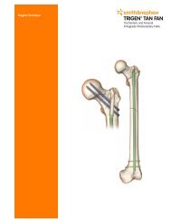
<strong>IT<strong>ST</strong></strong> Intramedullary <strong>Nail</strong> Surgical Technique 11<br />
Screw Options<br />
The <strong>IT<strong>ST</strong></strong> <strong>Nail</strong> accommodates both an<br />
11mm Lag Screw and a 6.5mm<br />
Anti-Rotation Screw. The Anti-Rotation<br />
Screw may be utilized in the case of<br />
certain fractures, where the bone stock<br />
and femoral neck/head bone stock is<br />
able to accommodate it. If only one screw<br />
is used, it must be the 11mm Lag Screw.<br />
Note: The 6.5mm Anti-Rotation Screw<br />
may be used to enhance fracture<br />
stability if the femoral neck is able to<br />
accommodate it; however, it should<br />
not be used if there is any concern that<br />
the femoral head or neck bone will not<br />
accommodate it. Failure to appropriately<br />
consider femoral head/neck bone mass<br />
and quality could result in implant<br />
cut-out.<br />
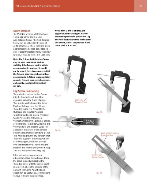
Lag Screw Positioning<br />
The projected path of the Lag Screw<br />
into the Femoral Head should be<br />
assessed using the C-arm (Fig. 26).<br />
This may be verified using the Screw<br />
Position Outrigger and the 3.2mm<br />
Threaded Guide Pin. Assemble the<br />
Outrigger into the <strong>IT<strong>ST</strong></strong> Proximal<br />
Targeting Guide and place a Threaded<br />
Guide Pin into the Anteversion<br />
Verification Hole in the proximal portion<br />
of the Proximal Targeting Guide (Fig. 27).<br />
Verify under C-arm that the Guide Pin<br />
appears in the center of the femoral<br />
neck in a superior/lateral view (Fig. 28).<br />
This will help prevent any parallax error.<br />
The outer aspect of the windowed arm<br />
of the Outrigger, which lies directly<br />
over the femoral neck, represents the<br />
superior and inferior position of the Lag<br />
and Anti-Rotation Screws (Fig. 29).<br />
If the nail anteversion requires<br />
adjustment, move the nail up or down<br />
the canal by gently impacting the<br />
Threaded Driver until the correct depth<br />
is achieved. Check the position of the<br />
nail with the C-arm. Adjusting nail<br />
depth may be useful in accommodating<br />
various femoral neck anatomies.<br />
Note: If the C-arm is off axis, the<br />
alignment of the Outrigger may not<br />
accurately predict the position of Lag<br />
and Anti-Rotation Screws. In the event<br />
this occurs, adjust the position of the<br />
C-arm until it is on axis.<br />
Fig. 26<br />
Fig. 28<br />
Lag Screw<br />
Projected Path<br />
Fig. 27<br />
Inferior Lag<br />
Screw Position<br />
Fig. 29<br />
Superior Anti-rotation<br />
Screw Position