- Page 1 and 2: Online catalogue Current to: 2013-0
- Page 3 and 4: Our ultrasonic expertise gives you
- Page 5 and 6: ::: Ultrasonic principle ::: Ruby r
- Page 7 and 8: The window mode is an extension of
- Page 9 and 10: The right solution for every applic
- Page 11 and 12: ::: Applications ::: Quality contro
- Page 13 and 14: ::: Applications ::: Detecting obst
- Page 15 and 16: The mounting distances should be re
- Page 17 and 18: Detection zones The detection zones
- Page 19 and 20: 0,25 m 30 mm blind zone 250 mm oper
- Page 21 and 22: The right solution for every applic
- Page 23 and 24: ::: References ::: pico pico-usp us
- Page 25: Description The mic+ sensor family
- Page 29 and 30: mic+25/D/TC scale drawing detection
- Page 31 and 32: mic+25/DD/TC scale drawing detectio
- Page 33 and 34: mic+25/IU/TC scale drawing detectio
- Page 35 and 36: mic+25/DIU/TC scale drawing detecti
- Page 37 and 38: mic+25/E/TC scale drawing detection
- Page 39 and 40: mic+25/EE/TC scale drawing detectio
- Page 41 and 42: mic+35/D/TC scale drawing detection
- Page 43 and 44: mic+35/DD/TC scale drawing detectio
- Page 45 and 46: mic+35/IU/TC scale drawing detectio
- Page 47 and 48: mic+35/DIU/TC scale drawing detecti
- Page 49 and 50: mic+35/E/TC scale drawing detection
- Page 51 and 52: mic+35/EE/TC scale drawing detectio
- Page 53 and 54: mic+130/D/TC scale drawing detectio
- Page 55 and 56: mic+130/DD/TC scale drawing detecti
- Page 57 and 58: mic+130/IU/TC scale drawing detecti
- Page 59 and 60: mic+130/DIU/TC scale drawing detect
- Page 61 and 62: mic+130/E/TC scale drawing detectio
- Page 63 and 64: mic+130/EE/TC scale drawing detecti
- Page 65 and 66: mic+340/D/TC scale drawing detectio
- Page 67 and 68: mic+340/DD/TC scale drawing detecti
- Page 69 and 70: mic+340/IU/TC scale drawing detecti
- Page 71 and 72: mic+340/DIU/TC scale drawing detect
- Page 73 and 74: mic+340/E/TC scale drawing detectio
- Page 75 and 76: mic+340/EE/TC scale drawing detecti
- Page 77 and 78:
mic+600/D/TC scale drawing detectio
- Page 79 and 80:
mic+600/DD/TC scale drawing detecti
- Page 81 and 82:
mic+600/IU/TC scale drawing detecti
- Page 83 and 84:
mic+600/DIU/TC scale drawing detect
- Page 85 and 86:
mic+600/E/TC scale drawing detectio
- Page 87 and 88:
mic+600/EE/TC scale drawing detecti
- Page 89 and 90:
These completely metal mic sensors
- Page 91 and 92:
Teach-in of a two-way reflective ba
- Page 93 and 94:
mic-25/D/M scale drawing detection
- Page 95 and 96:
mic-25/IU/M scale drawing detection
- Page 97 and 98:
mic-35/D/M scale drawing detection
- Page 99 and 100:
mic-35/IU/M scale drawing detection
- Page 101 and 102:
mic-130/D/M scale drawing detection
- Page 103 and 104:
mic-130/IU/M scale drawing detectio
- Page 105 and 106:
mic-340/D/M scale drawing detection
- Page 107 and 108:
mic-340/IU/M scale drawing detectio
- Page 109 and 110:
mic-600/D/M scale drawing detection
- Page 111 and 112:
mic-600/IU/M scale drawing detectio
- Page 113 and 114:
The vnp sensors extend the mic+ sen
- Page 115 and 116:
Configuration procedure for a vnp s
- Page 117 and 118:
vnp-25/DD/TC outputs output 1 switc
- Page 119 and 120:
vnp-25/IU/TC outputs output 1 analo
- Page 121 and 122:
vnp-35/DD/TC outputs output 1 switc
- Page 123 and 124:
vnp-35/IU/TC outputs output 1 analo
- Page 125 and 126:
vnp-130/DD/TC outputs output 1 swit
- Page 127 and 128:
vnp-130/IU/TC outputs output 1 anal
- Page 129 and 130:
vnp-340/DD/TC outputs output 1 swit
- Page 131 and 132:
vnp-340/IU/TC outputs output 1 anal
- Page 133 and 134:
vnp-600/DD/TC outputs output 1 swit
- Page 135 and 136:
vnp-600/IU/TC outputs output 1 anal
- Page 137 and 138:
Description The pico+ ultrasonic se
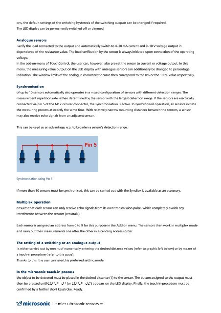
- Page 139 and 140:
Synchronisation using Pin 5 If more
- Page 141 and 142:
The advantages of IO IO-Link: Link:
- Page 143 and 144:
pico+25/F outputs output 1 switchin
- Page 145 and 146:
pico+25/WK/F outputs output 1 switc
- Page 147 and 148:
pico+35/F outputs output 1 switchin
- Page 149 and 150:
pico+35/WK/F outputs output 1 switc
- Page 151 and 152:
pico+100/F outputs output 1 switchi
- Page 153 and 154:
pico+100/WK/F outputs output 1 swit
- Page 155 and 156:
pico+25/I outputs output 1 analogue
- Page 157 and 158:
pico+25/WK/I outputs output 1 analo
- Page 159 and 160:
pico+25/U outputs output 1 analogue
- Page 161 and 162:
pico+25/WK/U outputs output 1 analo
- Page 163 and 164:
pico+35/I outputs output 1 analogue
- Page 165 and 166:
pico+35/WK/I outputs output 1 analo
- Page 167 and 168:
pico+35/U outputs output 1 analogue
- Page 169 and 170:
pico+35/WK/U outputs output 1 analo
- Page 171 and 172:
pico+100/I outputs output 1 analogu
- Page 173 and 174:
pico+100/WK/I outputs output 1 anal
- Page 175 and 176:
pico+100/U outputs output 1 analogu
- Page 177 and 178:
pico+100/WK/U outputs output 1 anal
- Page 179 and 180:
pico+15/F outputs output 1 switchin
- Page 181 and 182:
pico+15/WK/F outputs output 1 switc
- Page 183 and 184:
Description The sensors of the lpc
- Page 185 and 186:
- disconnecting the sensors’ supp
- Page 187 and 188:
lpc-25/CDD/M18 outputs output 1 swi
- Page 189 and 190:
lpc-25/CEE/M18 outputs output 1 swi
- Page 191 and 192:
lpc-25/CDU/M18 outputs output 1 ana
- Page 193 and 194:
lpc-25/CDI/M18 outputs output 1 ana
- Page 195 and 196:
lpc-25/CI/M18 outputs output 1 anal
- Page 197 and 198:
lpc-25/CU/M18 outputs output 1 anal
- Page 199 and 200:
Description The lcs+ ultrasonic sen
- Page 201 and 202:
Synchronisation using Pin 5 If more
- Page 203 and 204:
into the device itself Push-Pull ou
- Page 205 and 206:
lcs+600/F outputs output 1 switchin
- Page 207 and 208:
lcs+600/IU outputs output 1 analogu
- Page 209 and 210:
lcs+600/FD outputs output 1 switchi
- Page 211 and 212:
Description The lcs sensors have a
- Page 213 and 214:
synchronised with one another. To d
- Page 215 and 216:
lcs-25/DD/QP outputs output 1 switc
- Page 217 and 218:
lcs-25/IU/QP outputs output 1 analo
- Page 219 and 220:
lcs-25/DDD/QP outputs output 1 swit
- Page 221 and 222:
lcs-35/DD/QP outputs output 1 switc
- Page 223 and 224:
lcs-35/IU/QP outputs output 1 analo
- Page 225 and 226:
lcs-35/DDD/QP outputs output 1 swit
- Page 227 and 228:
lcs-130/DD/QP outputs output 1 swit
- Page 229 and 230:
lcs-130/IU/QP outputs output 1 anal
- Page 231 and 232:
lcs-130/DDD/QP outputs output 1 swi
- Page 233 and 234:
Description The compact sensor hous
- Page 235 and 236:
High counting frequencies, short re
- Page 237 and 238:
zws-15/CD/QS scale drawing detectio
- Page 239 and 240:
zws-15/CE/QS scale drawing detectio
- Page 241 and 242:
zws-15/CI/QS scale drawing detectio
- Page 243 and 244:
zws-15/CU/QS scale drawing detectio
- Page 245 and 246:
zws-24/CD/QS scale drawing detectio
- Page 247 and 248:
zws-24/CE/QS scale drawing detectio
- Page 249 and 250:
zws-24/CI/QS scale drawing detectio
- Page 251 and 252:
zws-24/CU/QS scale drawing detectio
- Page 253 and 254:
zws-70/CD/QS scale drawing detectio
- Page 255 and 256:
zws-70/CE/QS scale drawing detectio
- Page 257 and 258:
zws-70/CU/QS scale drawing detectio
- Page 259 and 260:
zws-70/CI/QS scale drawing detectio
- Page 261 and 262:
zws-7/CD/QS scale drawing detection
- Page 263 and 264:
zws-25/CD/QS scale drawing detectio
- Page 265 and 266:
zws-25/CE/QS scale drawing detectio
- Page 267 and 268:
zws-7/CE/QS scale drawing detection
- Page 269 and 270:
Our "smallest sensor": The sks sens
- Page 271 and 272:
Teach-in of a detect point A two tw
- Page 273 and 274:
sks-15/D scale drawing detection zo
- Page 275 and 276:
sks-15/CD scale drawing detection z
- Page 277 and 278:
sks-15/E scale drawing detection zo
- Page 279 and 280:
sks-15/CE scale drawing detection z
- Page 281 and 282:
The ucs sensors in a sturdy metal h
- Page 283 and 284:
Teach-in of a two-way reflective ba
- Page 285 and 286:
ucs-15/CDD/QM scale drawing detecti
- Page 287 and 288:
ucs-15/CEE/QM scale drawing detecti
- Page 289 and 290:
ucs-24/CDD/QM scale drawing detecti
- Page 291 and 292:
ucs-24/CEE/QM scale drawing detecti
- Page 293 and 294:
Wear-resistant PEEK film protects t
- Page 295 and 296:
or laptop with all conventional Win
- Page 297 and 298:
crm+35/D/TC/E outputs output 1 swit
- Page 299 and 300:
crm+35/DD/TC/E outputs output 1 swi
- Page 301 and 302:
crm+35/IU/TC/E outputs output 1 ana
- Page 303 and 304:
crm+130/D/TC/E outputs output 1 swi
- Page 305 and 306:
crm+130/DD/TC/E outputs output 1 sw
- Page 307 and 308:
crm+130/IU/TC/E outputs output 1 an
- Page 309 and 310:
crm+340/D/TC/E outputs output 1 swi
- Page 311 and 312:
crm+340/DD/TC/E outputs output 1 sw
- Page 313 and 314:
crm+340/IU/TC/E outputs output 1 an
- Page 315 and 316:
crm+600/D/TC/E outputs output 1 swi
- Page 317 and 318:
crm+600/DD/TC/E outputs output 1 sw
- Page 319 and 320:
crm+600/IU/TC/E outputs output 1 an
- Page 321 and 322:
crm+25/IU/TC/E outputs output 1 ana
- Page 323 and 324:
crm+25/DD/TC/E outputs output 1 swi
- Page 325 and 326:
crm+25/D/TC/E outputs output 1 swit
- Page 327 and 328:
Description For fill level measurem
- Page 329 and 330:
hps+25/DIU/TC/E/G1 scale drawing de
- Page 331 and 332:
hps+35/DIU/TC/E/G1 scale drawing de
- Page 333 and 334:
hps+130/DIU/TC/E/G1 scale drawing d
- Page 335 and 336:
hps+340/DIU/TC/E/G2 scale drawing d
- Page 337 and 338:
hps+340/DIU/TC/G2 scale drawing det
- Page 339 and 340:
hps+25/DD/TC/E/G1 scale drawing det
- Page 341 and 342:
hps+35/DD/TC/E/G1 scale drawing det
- Page 343 and 344:
hps+130/DD/TC/E/G1 scale drawing de
- Page 345 and 346:
hps+340/DD/TC/E/G2 scale drawing de
- Page 347 and 348:
hps+340/DD/TC/G2 scale drawing dete
- Page 349 and 350:
The wms sensors are designed for us
- Page 351 and 352:
wms-35/RT scale drawing detection z
- Page 353 and 354:
wms-130/RT scale drawing detection
- Page 355 and 356:
wms-340/RT scale drawing detection
- Page 357 and 358:
wms-600/RT scale drawing detection
- Page 359 and 360:
wms-25/RT/HV/M18 scale drawing dete
- Page 361 and 362:
The new ultrasonic double sheet con
- Page 363 and 364:
Paper, Film, Sheet material The mou
- Page 365 and 366:
Support through LinkControl dbk+4 c
- Page 367 and 368:
dbk+4/3CDD/M18 E+S scale drawing de
- Page 369 and 370:
dbk+4/WK/3CDD/M18 E+S scale drawing
- Page 371 and 372:
dbk+4/M18/3CDD/M18 E+S scale drawin
- Page 373 and 374:
dbk+4/M12/3CDD/M18 E+S scale drawin
- Page 375 and 376:
dbk+4/Empf/3CDD/M18 scale drawing d
- Page 377 and 378:
dbk+4/Sender/M18/K1 scale drawing d
- Page 379 and 380:
dbk+4/Empf/WK/3CDD/ M18 scale drawi
- Page 381 and 382:
dbk+4/Empf/M18/3CDD/ M18 scale draw
- Page 383 and 384:
dbk+4/Empf/M12/3CDD/ M18 scale draw
- Page 385 and 386:
dbk+4/Sender/ M12/K1 scale drawing
- Page 387 and 388:
dbk+4/3BEE/M18 E+S scale drawing de
- Page 389 and 390:
dbk+4/Empf/3BEE/M18 scale drawing d
- Page 391 and 392:
dbk+4/WK/3BEE/M18 E+S scale drawing
- Page 393 and 394:
dbk+4/Empf/WK/3BEE/ M18 scale drawi
- Page 395 and 396:
dbk+4/M18/3BEE/M18 E+S scale drawin
- Page 397 and 398:
dbk+4/Empf/M18/3BEE/ M18 scale draw
- Page 399 and 400:
dbk+4/M12/3BEE/M18 E+S scale drawin
- Page 401 and 402:
dbk+4/Empf/M12/3BEE/ M18 scale draw
- Page 403 and 404:
The dbk+5 extends the area of appli
- Page 405 and 406:
dbk+5/3CDD/M18 E+S scale drawing de
- Page 407 and 408:
dbk+5/Empf/3CDD/M18 scale drawing d
- Page 409 and 410:
dbk+5/Sender/M18/K1 scale drawing d
- Page 411 and 412:
dbk+5/3BEE/M18 E+S scale drawing de
- Page 413 and 414:
dbk+5/Empf/3BEE/M18 scale drawing d
- Page 415 and 416:
dbk+5/Sender/M18/K2 scale drawing d
- Page 417 and 418:
esp-4: Label and splice sensor comp
- Page 419 and 420:
esp-4 as thread sensor B) Separate
- Page 421 and 422:
esp-4/3CDD/M18 E+S outputs output 1
- Page 423 and 424:
esp-4/Empf/3CDD/M18 outputs output
- Page 425 and 426:
esp-4/M12/3CDD/M18 E+S outputs outp
- Page 427 and 428:
esp-4/Empf/M12/3CDD/ M18 outputs ou
- Page 429 and 430:
Description The functional principl
- Page 431 and 432:
esf-1/CDF scale drawing detection z
- Page 433 and 434:
esf-1/CF scale drawing detection zo
- Page 435 and 436:
The bks+ edge sensor facilitates th
- Page 437 and 438:
Keep your eyes open in data communi
- Page 439 and 440:
ks+3/FIU scale drawing detection zo
- Page 441 and 442:
ks+6/FIU scale drawing detection zo
- Page 443 and 444:
The bks edge sensor facilitates the
- Page 445 and 446:
ks-3/CIU scale drawing detection zo
- Page 447 and 448:
The LCA-2 facilitates the comfortab
- Page 449 and 450:
USB interface for PC connection Off
- Page 451 and 452:
LCA-2 scale drawing detection zone
- Page 453 and 454:
LCA-2 Koffer scale drawing detectio
- Page 455 and 456:
Ultrasound - is everything conceiva
- Page 457 and 458:
D-64560 Riedstadt telephone: 0 61 5
- Page 459 and 460:
Norway Primatec as Lillesandsveien
- Page 461 and 462:
America Right around the world, com
- Page 463 and 464:
telefax: +82 2 21 94-33 97 internet
- Page 465 and 466:
Oceania Right around the world, com