GHOST Pickup System Acousti-Phonic Intelligent Pre ... - Graph Tech
GHOST Pickup System Acousti-Phonic Intelligent Pre ... - Graph Tech
GHOST Pickup System Acousti-Phonic Intelligent Pre ... - Graph Tech

Create successful ePaper yourself
Turn your PDF publications into a flip-book with our unique Google optimized e-Paper software.
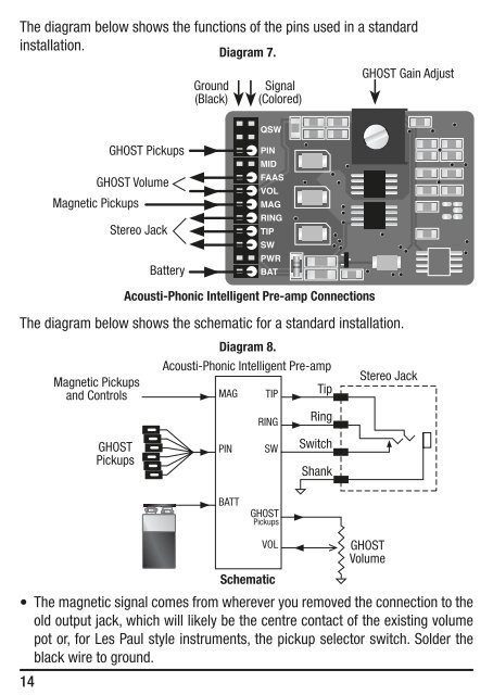
The diagram below shows the functions of the pins used in a standard<br />
installation.<br />
Diagram 7.<br />
The diagram below shows the schematic for a standard installation.<br />
•<br />
14<br />
Magnetic <strong>Pickup</strong>s<br />
and Controls<br />
<strong>GHOST</strong> <strong>Pickup</strong>s<br />
<strong>GHOST</strong> Volume<br />
Magnetic <strong>Pickup</strong>s<br />
Stereo Jack<br />
<strong>GHOST</strong><br />
<strong>Pickup</strong>s<br />
Battery<br />
Ground<br />
(Black)<br />
Diagram 8.<br />
<strong>Acousti</strong>-<strong>Phonic</strong> <strong>Intelligent</strong> <strong>Pre</strong>-amp<br />
MAG<br />
PIN<br />
Schematic<br />
Signal<br />
(Colored)<br />
<strong>Acousti</strong>-<strong>Phonic</strong> <strong>Intelligent</strong> <strong>Pre</strong>-amp Connections<br />
Stereo Jack<br />
<strong>GHOST</strong><br />
Volume<br />
The magnetic signal comes from wherever you removed the connection to the<br />
old output jack, which will likely be the centre contact of the existing volume<br />
pot or, for Les Paul style instruments, the pickup selector switch. Solder the<br />
black wire to ground.<br />
TIP<br />
RING<br />
SW<br />
BATT<br />
<strong>GHOST</strong><br />
<strong>Pickup</strong>s<br />
VOL<br />
Tip<br />
Ring<br />
Switch<br />
Shank<br />
<strong>GHOST</strong> Gain Adjust