GHOST Pickup System Acousti-Phonic Intelligent Pre ... - Graph Tech
GHOST Pickup System Acousti-Phonic Intelligent Pre ... - Graph Tech
GHOST Pickup System Acousti-Phonic Intelligent Pre ... - Graph Tech

Create successful ePaper yourself
Turn your PDF publications into a flip-book with our unique Google optimized e-Paper software.
Jazz<br />
Remove the strings and the bridge saddles from the guitar.<br />
Remove the entire bridge assembly.<br />
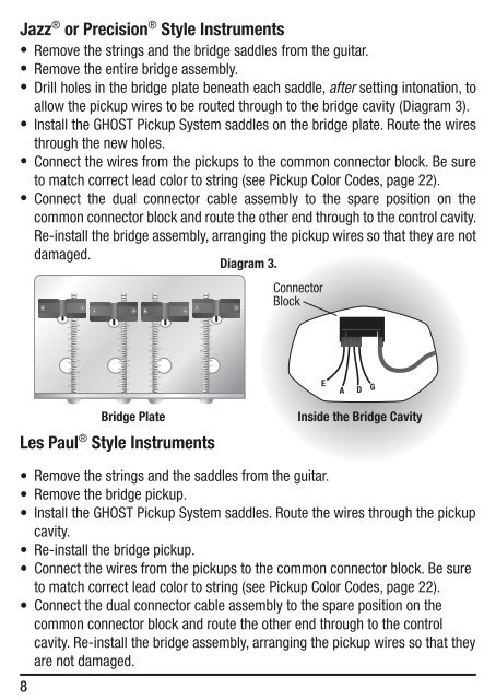
Drill holes in the bridge plate beneath each saddle, after setting intonation, to<br />
allow the pickup wires to be routed through to the bridge cavity (Diagram 3).<br />
Install the <strong>GHOST</strong> <strong>Pickup</strong> <strong>System</strong> saddles on the bridge plate. Route the wires<br />
through the new holes.<br />
Connect the wires from the pickups to the common connector block. Be sure<br />
to match correct lead color to string (see <strong>Pickup</strong> Color Codes, page 22).<br />
Connect the dual connector cable assembly to the spare position on the<br />
common connector block and route the other end through to the control cavity.<br />
Re-install the bridge assembly, arranging the pickup wires so that they are not<br />
damaged.<br />
® or <strong>Pre</strong>cision ® Style Instruments<br />
•<br />
•<br />
•<br />
•<br />
•<br />
•<br />
Diagram 3.<br />
Les Paul ® Style Instruments<br />
•<br />
•<br />
•<br />
•<br />
•<br />
•<br />
8<br />
Connector<br />
Block<br />
E<br />
A D G<br />
Bridge Plate Inside the Bridge Cavity<br />
Remove the strings and the saddles from the guitar.<br />
Remove the bridge pickup.<br />
Install the <strong>GHOST</strong> <strong>Pickup</strong> <strong>System</strong> saddles. Route the wires through the pickup<br />
cavity.<br />
Re-install the bridge pickup.<br />
Connect the wires from the pickups to the common connector block. Be sure<br />
to match correct lead color to string (see <strong>Pickup</strong> Color Codes, page 22).<br />
Connect the dual connector cable assembly to the spare position on the<br />
common connector block and route the other end through to the control<br />
cavity. Re-install the bridge assembly, arranging the pickup wires so that they<br />
are not damaged.