Pipe noise - PEUTZ CONSULT GmbH
Pipe noise - PEUTZ CONSULT GmbH
Pipe noise - PEUTZ CONSULT GmbH

Create successful ePaper yourself
Turn your PDF publications into a flip-book with our unique Google optimized e-Paper software.
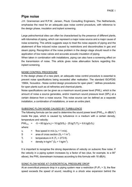
<strong>Pipe</strong> <strong>noise</strong><br />
PAGE 1<br />
J.H. Granneman and R.P.M. Jansen, Peutz Consulting Engineers, The Netherlands,<br />
emphasise the need for an adequate pipe <strong>noise</strong> control procedure, with reference to<br />
the design phase, insulation and inplant screening.<br />
Large petrochemical sites can often be characterised by the presence of different plants,<br />
with kilometres of piping, which can represent a major <strong>noise</strong> source and a major cause of<br />
<strong>noise</strong> screening. This article suggests ways to treat the <strong>noise</strong> aspects of piping and the<br />
abatement of flow induced <strong>noise</strong> caused by restrictions and discontinuities in gas and<br />
steam piping. Recognition of the <strong>noise</strong> problem in the design stage should result in the<br />
application of low <strong>noise</strong> valves and accurate acoustic insulation of piping.<br />
When taken in combination with installations, piping can also have a screening effect on<br />
the transmission of <strong>noise</strong>. This article gives <strong>noise</strong> attenuation factors regarding this<br />
inplant screening.<br />
NOISE CONTROL PROCEDURE<br />
In the design phase of a new plant, an adequate <strong>noise</strong> control procedure is essential to<br />
prevent <strong>noise</strong> specifications being exceeded after realisation. The standard ISO/FDIS<br />
15664, ‘Acoustics - Noise control design procedures for open plant’, 1 defines procedures<br />
for open plants such as oil refineries and chemical plants.<br />
Noise specifications can be given as a maximum sound power level (PWL), which is the<br />
amount of <strong>noise</strong> a source generates, and/or maximum sound pressure level (SPL) at a<br />
certain distance from a <strong>noise</strong> source. This <strong>noise</strong> source can be defined as a separate<br />
installation, a combination of installations, or even an entire plant.<br />
SUBSONIC FLOW NOISE CAUSED BY TURBULENCE<br />
The following formula can be used to determine the sound power level (PWLins in dB(A) 2 )<br />
inside the pipe, which is caused by turbulence in a medium with a certain density,<br />
temperature and velocity:<br />
PWLins = -5 + 60.lg(vf/v0) + 10.lg(S/S0) - 25.lg(Tf/T0) + 8.6.lg(Df/D0)<br />
where:<br />
vf = flow speed in m/s (v0 = 1 m/s).<br />
S = area of cross section (S0 = 1 m 2 ).<br />
Tf = temperature in K (T0 = 273 K).<br />
Df = density in kg/m 3 (D0 = 1 kg/m 3 ).<br />
It is important to recognise the strong dependence of velocity on subsonic flow <strong>noise</strong>. If<br />
the velocity in a piping system increases by a factor of two (due, for example, to a 90 o<br />
elbow), the PWL downstream increases according to this formula with 18 dB(A).<br />
SONIC FLOW NOISE AT OVERCRITICAL PRESSURE DROP<br />
At an overcritical pressure drop in a piping system near a restriction (P1/P2 > 3), the flow<br />
speed exceeds the speed of sound, resulting in a shock wise expansion behind the
PAGE 2<br />
restriction (shock waves). This mechanism is the most important cause of high sound<br />
pressure levels near valves, restriction orifices etc.<br />
The most important criteria for sonic flow <strong>noise</strong> follow from the formula regarding the<br />
generated sound power level (below):<br />
PWLins = 10.lg(W 2 .(ΔP/P1) 3.6 .(T/MW) 1.2 ) + 126<br />
where:<br />
W = flowrate in kg/s.<br />
ΔP = pressure drop in kPa.<br />
P1 = up stream pressure in kPa.<br />
T = temperature in K.<br />
MW = molecular weight.<br />
The T/MW ratio provides an indication of the ratio between the flow speed and the speed<br />
of sound. The formula shows a strong pressure drop dependency.<br />
Figure 1: Difference between PWLins and SPL1m
PAGE 3<br />
DETERMINATION OF DIFFERENCE BETWEEN PWLins AND SPL1m<br />
In practice, setting limits according to company guidelines often means that a certain<br />
sound pressure level (SPL) at 1 m from a sound source should not be exceeded. In the<br />
case of hearing loss prevention, the value of 85 dB(A) is often used. In order to recognise<br />
potential sound problems, an insight must be obtained into the difference between the<br />
sound power level inside a pipe (PWLins) and the SPL at 1 m (SPL1m) as shown in<br />
Figure 1.<br />
In Figure 1, the insulation value (R) of the piping is the relevant parameter. If steel piping<br />
with a schedule 60 - 80 (being common values for gas and steam piping) is used with<br />
diameters of 6 - 10 in., the sound insulation value (R) is 44 - 48 dB for high frequency<br />
<strong>noise</strong>. The difference between PWLins and SPL1m is approximately 36 - 40 dB.<br />
In practice, acoustic problems can therefore occur, beginning with PWLs inside the<br />
piping of approximately 120 dB(A).<br />
TURBULENCE GENERATOR WITH SOUND RADIATING SURFACES<br />
Typical turbulence amplifiers in piping systems, generating shock waves in many cases,<br />
are:<br />
• Control valves.<br />
• Restriction orifices.<br />
• Tees.<br />
• Elbows.<br />
Typical sound radiating surfaces are:<br />
• (Non-insulated) piping.<br />
• Piping supports (Figure 2).<br />
• Flanges.<br />
• Control valves.<br />
• Instrumentation.
Figure 2: Insulation of piping supports.<br />
PAGE 4<br />
The design stage of a gas or steam piping system should be used to determine potential<br />
acoustic problems. Given the company limit setting and the prognosis of SPL1m, the<br />
<strong>noise</strong> abatement policy should be:<br />
• Prevention of sound generation in the design phase by limiting flow speeds and<br />
preventing unnecessary turbulence amplification.<br />
• Measures at (potential) turbulence amplifiers.<br />
• Sound insulation.<br />
This policy can also be used for <strong>noise</strong> abatement in existing situations, although given<br />
the existing pipe diameters and flows, measures to reduce the flow speed are often not<br />
feasible.<br />
NOISE ABATEMENT AT THE SOURCE<br />
Some acoustic measures, which aim to influence the origin of sound, are given below.<br />
Piping design<br />
Piping to and from a (<strong>noise</strong> critical) control valve has to be designed so that the<br />
turbulence caused by the valve is not further amplified due to nearby elbows. The<br />
distance between elbow and valve (piping to the valve) has to be 10 times the diameter<br />
of the pipe. The distance between valve and elbow (piping from the valve) has to be 20<br />
times the diameter of the pipe.<br />
Junctions should not be made at an angle of 90 o , but rather should follow smooth curves.
Valves<br />
PAGE 5<br />
Figure 3 shows an example of a turbulence reducing flow divider, applied as a standard<br />
in low <strong>noise</strong> control valves.<br />
Figure 3: A turbulence reducing flow divider.<br />
If a valve only has a cut off function, a ball valve is preferred over a globe valve for<br />
prevention of turbulence. Another example of prevention of <strong>noise</strong> generation is to create<br />
a pressure drop in stages (Figure 4).
Figure 4: Pressure drop in stages.<br />
Restriction orifices<br />
PAGE 6<br />
A restriction orifice can be made with one hole or a number of holes. While the free<br />
crosssection areas are the same in both cases, the reduction of turbulence in the orifice<br />
with several holes, as compared with a single hole, can reach approximately<br />
7.lg(n) dB(A), where n is the number of holes.<br />
Muffler<br />
In an effective muffler, gas flows through a diffuser in combination with sound absorbing<br />
material (steel wool and/or rock wool). As the muffler only reduces sound radiating at the<br />
downstream side of piping, insulation of the muffler housing itself, including the nearby<br />
turbulence generating valve, can also be necessary.<br />
INSULATION<br />
Effect limitations<br />
Acoustical insulation of sound radiating surfaces is an effective and relatively cheap way<br />
of reducing the high frequency flow <strong>noise</strong> radiated by piping, piping supports,<br />
instrumentation, etc.<br />
In practice, piping will often be constructed as a thermal insulation. However, this can<br />
only provide effective sound insulation if it is mounted in an acoustically correct way.
Sound insulating construction<br />
PAGE 7<br />
Acoustic insulation is generally constructed using a metal outer layer or cladding (steel or<br />
aluminium) without any rigid connections with the pipe. Acoustic leaks are avoided using<br />
adequate overlaps and sealings. Between the outer layers and the pipe wall, a porous<br />
layer is generally provided, for instance mineral fibre (glass or rock) or open cell flexible<br />
plastic foam.<br />
The mass of the outer layer needs to be sufficient to obtain the required level of<br />
insulation. Table 1 gives insulation classes based on the recent standard<br />
ISO/FDIS 15665 3 .<br />
Table 1 Minimum insertion loss required for each class 3<br />
Class<br />
A1<br />
A2<br />
A3<br />
B1<br />
B2<br />
B3<br />
C1<br />
C2<br />
C3<br />
Range of nominal diameter<br />
(D, mm)<br />
D < 300<br />
300 ≤ D < 650<br />
650 ≤ D < 1000<br />
D < 300<br />
300 ≤ D < 650<br />
650 ≤ D < 1000<br />
D < 300<br />
300 ≤ D < 650<br />
650 ≤ D < 1000<br />
Octave band centre frequency (Hz)<br />
125 250 500 1 000 2 000 4 000 8 000<br />
-4<br />
-4<br />
-4<br />
-9<br />
-9<br />
-7<br />
-5<br />
-7<br />
1<br />
-4<br />
-4<br />
2<br />
Minimum insertion loss (dB)<br />
In order to conform to a given class, the insertion loss of all seven octave bands will<br />
either exceed or be equal to the levels specified.<br />
Sound insulation at low frequencies can be negative due to the mass spring resonance<br />
and, with smaller pipe diameters, the increase of the <strong>noise</strong> radiating surface of the outer<br />
cladding. This means that in these frequency bands, sound radiation increases as a<br />
result of sound insulation.<br />
Effective insulation<br />
Effective insulation of pipe systems means that each part of the system with a SPL1m<br />
higher than the limit must be insulated. In many cases, supports and parts of the<br />
instrumentation that are linked directly to the sound radiating pipe wall also have to be<br />
insulated. In some cases, and as an alternative to the insulation of supports, vibration<br />
insulators can be applied between a pipe and its support within the acoustic insulation.<br />
If, for maintenance reasons, the insulation must be taken off and again be applied in a<br />
simple way, removable enclosures should be applied. An example of insulation in a case<br />
where the flange has to be ventilated is given in Figure 5 3 .<br />
-3<br />
-3<br />
2<br />
-1<br />
4<br />
9<br />
2<br />
2<br />
7<br />
3<br />
6<br />
11<br />
11<br />
14<br />
17<br />
9<br />
9<br />
13<br />
11<br />
15<br />
20<br />
23<br />
24<br />
26<br />
16<br />
16<br />
19<br />
19<br />
24<br />
29<br />
34<br />
34<br />
34<br />
22<br />
22<br />
24<br />
27<br />
33<br />
36<br />
38<br />
38<br />
38<br />
29<br />
29<br />
30<br />
35<br />
42<br />
42<br />
42<br />
42<br />
42
Figure 5: Vented acoustic insulation of flanged joints.<br />
ATTENTUATION FACTORS DUE TO INPLANT SCREENING<br />
PAGE 8<br />
In the design phase of a new plant, one usually starts by adding up the sound power<br />
levels of separate apparatus, installations and piping. This prognosis can be based on<br />
<strong>noise</strong> data obtained from manufacturers and/or experimental data. As a result of<br />
neglecting inplant screening, the sum of these different sound power levels generally<br />
provides an exaggerated view of the total <strong>noise</strong> emissions of the plant, particularly when<br />
a relatively high density of piping and other equipment surrounds the most dominant<br />
<strong>noise</strong> sources. 4<br />
Inplant screening is defined as the excess attenuation of sound due to diffraction and<br />
absorption when transmitted through open process installations. Generally applicable<br />
attenuation factors are derived for situations where relevant inplant screening is<br />
expected, but where they cannot be determined by practical measurements (in case of<br />
predictions or too much disturbing <strong>noise</strong> in practice). These values of attenuation<br />
factors 5 are incorporated in the revised Dutch guideline regarding measuring and<br />
calculating industrial <strong>noise</strong>, (issued in April 1999). 6 However, if inplant screening is to<br />
be considered, one should not take into account screening/reflection due to buildings<br />
and other objects in the plant of interest.<br />
The reduction (D), due to inplant screening, is calculated according to the following<br />
formulae:<br />
D = t(f) . rt (1)<br />
D # Dmax (2)<br />
where:<br />
t(f) = Frequency depended factor regarding inplant screening [dB/m]; indicative<br />
rt<br />
factors are given in Table 2.<br />
= Part of the <strong>noise</strong> path through the open process installation (Figure 6). Only<br />
the part of the curved sound path that transmits through the installations is
PAGE 9<br />
considered as part of rt; the part mainly above the installations is not taken into<br />
account. In the Dutch guideline the radius R of the curved sound path is<br />
defined as R = 8.r, where r is the distance between the sound source and the<br />
receiving point.<br />
Dmax = Maximum type dependent reduction (Table 2).<br />
The values of these attenuation factors are highly dependent on the specific features<br />
and ‘density’ of piping and equipment in the plant. The more installations present, the<br />
more reflection and diffraction of <strong>noise</strong> will occur, causing a higher inplant screening<br />
effect. In existing situations, it is preferable to measure the excess attenuation of this<br />
inplant screening effect. Special measurement and analytical techniques using cross<br />
correlation can diminish the problem of disturbing <strong>noise</strong> 5 . In the case of other<br />
situations, Table 2 provides indicative values for three different plant types. Type A<br />
relates to plants with a density of installations of approximately 20%/30 m transmission<br />
path length through the plant (in the relevant direction). Type B relates to plants with a<br />
density of more than 20 %. ‘Tank parks’ values concern areas with a high number of<br />
storage tanks.<br />
Table 2 Indicative values of attenuation factor t (f) due to inplant screening (dB/m)<br />
Description 31.5 63 125 250 500 1 000 2 000 4 000 8 000<br />
type A 0 0 0.02 0.03 0.06 0.09 0.1 0.1 0.1 10<br />
type B 0 0 0.04 0.06 0.11 0.17 0.2 0.2 0.2 20<br />
tank parks 0 0 0.002 0.005 0.005 0.02 0.02 0.02 0.02 10<br />
Figure 6: Explanation of rt.<br />
The sound pressure levels in the (living) area around an existing industrial site, with<br />
many separate open process plants, are often determined by means of a computer<br />
model in which the contribution of each plant to the sound pressure level at certain<br />
points in the surrounding area is calculated. The necessary sound power levels of<br />
Dmax [dB]
PAGE 10<br />
separate plants are often based on ‘contour measurements’ around each plant, in<br />
accordance with ISO 8297 7 . In these situations, the application of inplant screening<br />
attenuation factors has proven to be very useful when the emitted sound of a certain<br />
plant is transmitted through adjacent open plant(s).<br />
Neglecting this excess attenuation can cause significant differences between<br />
calculated and measured sound levels in the surrounding areas, and as a<br />
consequence strongly influences the need and extent of sound reduction measures. If<br />
measurement of the reduction effect of inplant screening is not possible, the inplant<br />
screening factors, as mentioned in Table 2, can be useful.<br />
CONCLUSION<br />
In the design phase of an open plant, adequate <strong>noise</strong> control procedures such as<br />
ISO/FDIS 15664 are essential. Noise aspects of piping are important in open plants<br />
because of the vast number of pipe systems. When sound limits must be met at 1 m from<br />
pipe systems, valves, etc., the acoustic behaviour of the system should be foreseen in<br />
the design phase.<br />
Noise abatement at the source can significantly reduce sound emissions, and can<br />
sometimes lead to the elimination of the sound source. Implementation in existing<br />
situations is more expensive than the recognition of potential acoustic problems and<br />
determination of measures in the design phase.<br />
Given the contributions of specific parts of the pipe system, sound insulation must be<br />
executed with great care if it is to be effective.<br />
When <strong>noise</strong> limits must be met in the environment of an industrial plant, inplant screening<br />
must be considered because, due to this effect, the real emissions of an industrial plant<br />
might be lower than those calculated.<br />
REFERENCES<br />
1. ISO/FDIS 15664, Acoustics – Noise Control design procedures for open plant, 2001.<br />
2. ‘Geräusche bei Rohrleitungen; (‘Noise at pipes’)’, VDI Handbuch Lärmminderung<br />
3733, July 1996.<br />
3. ISO/FDIS 15665, Acoustics - Acoustic insulation for pipes, valves and flanges, 2003.<br />
4. Granneman J.H., Jansen R.P.M., ‘Sound power determination of large open plants;<br />
comparison of alternative methods’, Inter<strong>noise</strong> 99, December 1999.<br />
5. Granneman J.H., Beer E.H.A. de, Schermer F.A.G.M., ‘Inplant screening in<br />
petrochemical sites’, Inter<strong>noise</strong> 93, August 1993.<br />
6. ‘Guide for measuring and calculating industrial <strong>noise</strong>’, guideline issued by Dutch<br />
Ministry of Environment, April 1999.<br />
7. ISO 8297, Acoustics – Determination of sound power of multisource industrial plants<br />
for evaluation of sound pressure levels in the environment’, Engineering Method,<br />
1994.