oscillating line - Kendrion Binder
oscillating line - Kendrion Binder
oscillating line - Kendrion Binder

You also want an ePaper? Increase the reach of your titles
YUMPU automatically turns print PDFs into web optimized ePapers that Google loves.
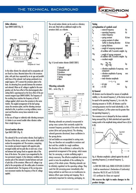
In<strong>line</strong> vibrators<br />
Type OMW516002 (Fig. 3)<br />
Armature plate<br />
the technical background<br />
In the in<strong>line</strong> vibrator the solenoid and its energisation coil<br />
are fixed to a base. Mounted above this is the armature<br />
plate, with pole faces separated by an air gap and parallel<br />
with those of the solenoid. Leaf springs positioned at an<br />
angle (approx. 20°) connect the armature plate to the<br />
base. An attracting force prevails between the armature<br />
and solenoid. When an AC voltage is applied to the energisation<br />
coil, the force effect of the electromagnetic alternating<br />
field is superimposed on the force effect of the permanent<br />
magnet (type OMW516004). The frequency of<br />
the resulting force matches the frequency of the AC<br />
voltage applied, which moves the armature in the same<br />
rhythm. The angled arrangement of the leaf springs<br />
causes the armature plate, and the vibrating conveyor<br />
attached to this, to perform a curving oscillatory movement<br />
and therefore convey loose materials in one<br />
direction.<br />
In the case of larger or relatively wide vibrating conveyors<br />
it is better to use several smaller in<strong>line</strong> vibrators rather<br />
than a single large one.<br />
Curved motion vibrator<br />
Type OAB513001 (Fig. 4)<br />
Sprung component<br />
Unsprung component<br />
Leaf spring<br />
Base<br />
Solenoid<br />
(energisation coil + frame)<br />
The solenoid of the curved motion vibrator, fixed rigidly to<br />
the base of the device, consists of two annular shells which<br />
enclose the energisation coil. The armature, comprising<br />
two annular permanent magnets with opposite poles<br />
arranged axially and two pole discs in each case, is located<br />
between leaf springs fixed on opposite sides of the<br />
base of the device. The system is pre-magnetised by the<br />
two permanent magnets. In the stationary condition one<br />
annular pole of the solenoid is located between each pair<br />
of pole discs of the armature. When an AC voltage is applied<br />
to the energisation coil, the unlike poles of armature<br />
and solenoid attract. The frequency of the curving armature<br />
movement matches the frequency of the AC voltage<br />
applied.<br />
The curved motion vibrator can be used as a vibratory<br />
drive and, fitted with an additional weight on the<br />
armature shaft, as a vibrator.<br />
Fig. 4: Curved motion vibrator (OAB513001)<br />
1 Solenoid<br />
2 Energisation coil<br />
3 Armature<br />
4 Permanent magnet<br />
5 Spring<br />
6 Base<br />
Vibrating solenoids<br />
OAC... series (Fig. 5)<br />
Sprung load<br />
Sprung<br />
component<br />
Unsprung<br />
load<br />
Unsprung<br />
component<br />
Vibrating<br />
solenoid<br />
Vibrating solenoids are primarily incorporated in<br />
spring–mass systems that constantly exploit the<br />
resonant frequency proximity of the entire vibrating<br />
system (drive and sprung device). The vibrating<br />
solenoid generates directional, <strong>line</strong>ar oscillations in<br />
the sprung device.<br />
Coil and bobbin are encapsulated in casting resin.<br />
They are therefore not susceptible to moisture and<br />
dust and thus suitable for rough conditions.<br />
The direction of the oscillations is achieved by the<br />
geometrical arrangement of the springs, which means<br />
that, for conveying, a certain <strong>oscillating</strong> angle is<br />
always necessary. The effective amplitude here corresponds<br />
to twice the amplitude of the <strong>oscillating</strong> frequency<br />
of the whole system. Vibrating solenoids can<br />
be infinitely regulated via the operating voltage. They<br />
reach the full conveying power immediately after<br />
being switched on and there are no troublesome imbalance<br />
effects upon starting and stopping. This is<br />
particularly important for metering, packaging, etc.<br />
www.kendrionmt.com<br />
Armature plate<br />
∆L = air gap<br />
Tuning<br />
a) Explanation of symbols used<br />
fo fa = natural frequency<br />
= operating frequency<br />
= mains frequency<br />
Hz<br />
Hz<br />
c = spring constant N/mm<br />
cs = spring constant of rubber<br />
buffer in shearing direction N/mm<br />
d = spring thickness mm<br />
mF = weight of unsprung component<br />
mN of oscillator with 2 eccentric weights kg<br />
= weight of sprung component<br />
of oscillator with 2 eccentric weights kg<br />
mR = resultant weight<br />
mR =<br />
m .<br />
N mF<br />
mN + mF kg<br />
sF = vibration amplitude of unsprung mm<br />
component<br />
sN = vibration amplitude of sprung<br />
component<br />
mm<br />
s = total vibration amplitude<br />
s = sF + sN mm<br />
a = air gap mm<br />
1N = 0.102 kg<br />
b) General<br />
All vibrators must be detuned for reasons of amplitude<br />
stability, i.e. the natural frequency fo of the device must not<br />
be equal to the operating frequency fa. As a rule, the<br />
detuning amounts to 10-20%. All vibrators used for<br />
conveying purposes must be tuned subcritically, i.e. the<br />
natural frequency fo of the system must be greater than<br />
the operating frequency fa. The resonance curve is damped by the loose materials<br />
being conveyed (Fig. 6). Both subcritical and supercritical<br />
tuning results in the amplitude being reduced from a (A) to<br />
b (B).<br />
Subcritical tuning<br />
Damped curve<br />
1<br />
Supercritical<br />
tuning<br />
Fig. 6: Vibration amplitude s plotted against the ratio of<br />
operating frequency fa to natural frequency f0. Notes:<br />
- to DIN VDE 0580 (July 2000) ICS29.020.53.020.01<br />
(valid as manufacturer’s Declaration of Conformity)<br />
- directives 98/37/EC and 73/23/EEC<br />
- CCC certificate for China not required<br />
We reserve the right to make changes to the<br />
product design.<br />
5