Spare Parts E - Kendrion Binder
Spare Parts E - Kendrion Binder
Spare Parts E - Kendrion Binder

You also want an ePaper? Increase the reach of your titles
YUMPU automatically turns print PDFs into web optimized ePapers that Google loves.
BINDER<br />
kec<br />
group<br />
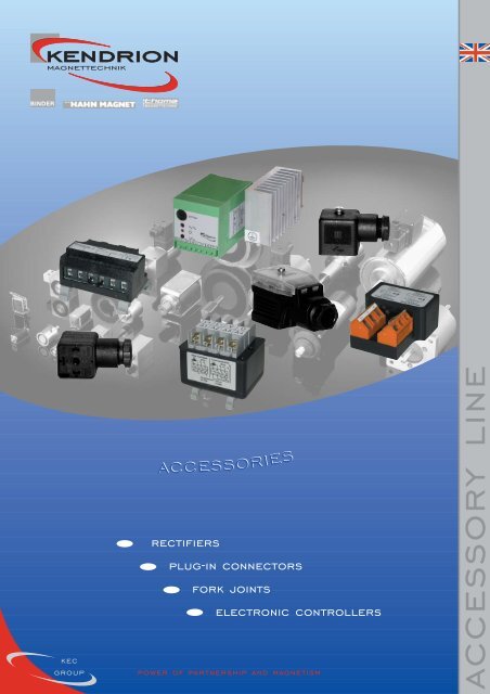
accessories<br />
rectifiers<br />
plug-in connectors<br />
fork joints<br />
electronic controllers<br />
power of partnership and magnetism<br />
accessory line
about us<br />
The KENDRION ELECTROMAGNETIC COMPONENTS Group<br />
(KEC Group) sees itself as a centre of excellence in the field<br />
of electromagnetism.<br />
KENDRION MAGNETTECHNIK GmbH develops and<br />
manufactures a wide range of electromagnetic products in<br />
the most diverse variations and designs for countless<br />
technical applications. The company grew out of the<br />
traditional operations of <strong>Binder</strong>, Thoma and Neue Hahn<br />
and is now Europe’s leading manufacturer of electromagnetic<br />
components.<br />
Our many years of experience in the development and<br />
manufacture of electromagnetic devices plus the skills and<br />
commitment of our employees enable us to recognise the<br />
needs of the market. And we turn those needs into highquality<br />
products in cooperation with our customers.<br />
We at KENDRION MAGNETTECHNIK achieve customerfocused<br />
solutions in all corporate divisions. Those solutions<br />
bring maximum benefits for customers and hence<br />
considerably strengthen their position in their markets.<br />
Project work is our focal point. We at KENDRION<br />
MAGNETTECHNIK take this to mean the joint development<br />
of devices together with our customers, taking into<br />
account special operating conditions, special requirements<br />
and high economic efficiency. Our objective is to provide<br />
the market with the devices it needs. With optimised costsbenefits<br />
ratios to secure the competitiveness of our<br />
customers.<br />
• Customer-centred market management,<br />
• innovative product developments,<br />
• lean, flexible logistics,<br />
• high quality standards,<br />
• affordable prices,<br />
• and the power of magnetism<br />
guarantee the success of<br />
KENDRION MAGNETTECHNIK.<br />
kendrion magnettechnik<br />
-<br />
your one-stop solution<br />
2<br />
www.kendrionmt.com
contents<br />
Types 32 073<br />
page 4<br />
Types 32 173 / 33 433<br />
page 5<br />
GDSB211<br />
GDSBV211<br />
page 6<br />
GD 311 page 7 GD 209<br />
page 7<br />
Fork joints<br />
page 7<br />
Snap-on fork pins<br />
page 7<br />
Type 33 53501A00<br />
page 8<br />
Types 33 43304B00<br />
and 33 43303B00<br />
page 10<br />
www.kendrionmt.com 3
ectifiers<br />
Half-wave and bridge rectifiers Half-wave and bridge rectifiers Half-wave and bridge rectifiers<br />
Types<br />
Half-wave and bridge rectifiers for<br />
small connection boxes<br />
Types<br />
Half-wave and bridge rectifiers with<br />
CE symbol<br />
Types<br />
Bridge rectifiers for heavy-duty<br />
applications<br />
Half-wave<br />
32 07333H00<br />
Half-wave 32 07322A40<br />
Bridge<br />
32 07334H00<br />
Bridge<br />
32 07323A40<br />
Bridge<br />
32 07350A00<br />
32.5<br />
13<br />
50<br />
50<br />
30<br />
22<br />
45.5<br />
55.5<br />
43.6 22.5<br />
145<br />
43<br />
58.6<br />
Voltage/ up to 400<br />
VAC ± 10%<br />
Current/ADC up to 2<br />
Voltage/ bridge: up to 415; half-wave: up to 500<br />
VAC ± 10%<br />
Current/ADC up to 2<br />
Voltage/ up to 400<br />
VAC ± 10%<br />
Current/ADC up to 4<br />
Other<br />
features<br />
• contacts for switching on DC side<br />
• moulded housing<br />
Other<br />
features<br />
• contacts for switching on DC side<br />
• CE symbol<br />
Other<br />
features<br />
• contacts for switching on DC side<br />
• moulded housing<br />
Options<br />
available<br />
• bridge version with lead wires and<br />
CE symbol 32 07334J01<br />
Options • mounting rail set 32 07322A00103<br />
available • adhesive pad 32 07322A00104<br />
• mounting clip 32 07322A00101<br />
• version with lead wires<br />
• version for up to 575 VAC, 1 ADC,<br />
half-wave<br />
• universal version, bridge and<br />
half-wave, with integral DC<br />
switching circuit<br />
4<br />
www.kendrionmt.com
technische rectifiers erläuterungen<br />
Overvolting rectifiers Overvolting rectifiers Overvolting rectifiers<br />
Types<br />
Rectifiers with overvolting feature,<br />
full-/half-wave switchover,<br />
space-saving design<br />
Types<br />
Rectifiers with overvolting feature,<br />
full-/half-wave switchover,<br />
universal usage<br />
Types<br />
Overvolting rectifiers with adjustable<br />
holding voltage, for heavy-duty<br />
applications<br />
32 17320A..<br />
32 17350E.. (A)<br />
32 17353E.. (B)<br />
33 43310A..<br />
33 43311A..<br />
33 43312A..<br />
32.2<br />
55.5 (A)<br />
55.2 (B)<br />
Dim./<br />
mm<br />
...10A03<br />
...11A03<br />
...10A00<br />
...12A03<br />
50<br />
30<br />
42.5<br />
55.5<br />
43<br />
T<br />
B2<br />
B1<br />
B1<br />
B2<br />
T<br />
45<br />
45<br />
105<br />
62.5 62.5<br />
62.5 102.5<br />
105 107<br />
145<br />
43 13<br />
58.6 45.5<br />
75<br />
Voltage/ ...Ax3 100...230<br />
VAC±10% ...Ax0 220...415<br />
Current/ADC ...Ax0 up to 2 / 1<br />
...Ax3 up to 3 / 1.5<br />
Over- ...A0x 0.3<br />
volting ...A2x 1.3<br />
time/s<br />
Other<br />
features<br />
• contacts for switching on DC side<br />
• CE symbol<br />
• compatible upgrade for rectifier<br />
32 0732xAxx<br />
Options • mounting rail set 32 07322A00103<br />
available • adhesive pad 32 07322A00104<br />
• mounting clip 32 07322A00101<br />
• version with lead wires<br />
• version with integral DC switching<br />
circuit<br />
Voltage/ ...Ex4 48 ... 120<br />
VAC±10% ...Ex0 220 ... 415<br />
...Ex8 460 ... 525<br />
Current/ADC all up to 6 / 3<br />
Over- ...EOx 0.25 / 1<br />
volting ...E2x 1.8 / 3<br />
time/s<br />
Other<br />
features<br />
Options<br />
available<br />
• contacts for switching on DC side<br />
• CE symbol<br />
• moulded housing<br />
• bridge allows selection of overvolting<br />
time<br />
• compatible upgrade for rectifier<br />
32 07350A00<br />
• version with PG-threaded cable gland<br />
• version for installation on mounting rail<br />
Voltage/ ...Ax3 100 ... 120, 220 ... 230<br />
VAC±10% ...Ax0 380 ... 415<br />
Current/ADC ...10A03 up to 4 / 2<br />
...10A00 up to 6 / 3<br />
...11A03 up to 8 / 4<br />
...12A03 up to 18 / 9<br />
Over- ...10Axx, 11Axx 0.15 ... 3<br />
volting ...12Axx 0.2 ... 4<br />
time/s<br />
Other<br />
features<br />
Options<br />
available<br />
• contacts for switching on DC side<br />
• CE symbol<br />
• de-energised switching possible<br />
• overvolting time and holding<br />
voltage adjustable with potentiometer<br />
• integral fuse<br />
• various default settings<br />
www.kendrionmt.com<br />
5
plug-in connectors with rectifier<br />
CE<br />
These components are not electronic or electrical<br />
devices in the meaning of the Machinery<br />
Directive 98/37/EC, but instead are merely<br />
intended for incorporation in other machines or<br />
systems, and are not for use by end-users. The user<br />
must guarantee that his end product complies with<br />
the appropriate directives.<br />
GDSB211<br />
27.5<br />
GDSBV211<br />
34<br />
Low Voltage Directive 73/23/EEC.<br />
We declare compliance with the following standards:<br />
HD625.1 S1 (1996)<br />
IEC 60529 (1991<br />
27.5<br />
52<br />
Ø 22.5<br />
34<br />
18<br />
72<br />
The products are components in the meaning of the<br />
Machinery Directive 98/37/EC. According to<br />
this directive, such products incorporated in a<br />
machine may not be operated until said machine’s<br />
conformity with the EC directive has been established.<br />
35<br />
39<br />
A manufacturer’s declaration can be obtained on<br />
request.<br />
7<br />
M3<br />
7<br />
M3<br />
Type GDSB 211<br />
plug-in connector DIN EN 175301-803 (DIN 43650-A)<br />
with integral rectifier GDSB 211<br />
max. 230 VAC ±10% / 2 ADC<br />
order No: 314 1051<br />
Plug-in connectors<br />
2-pole plug-in connectors with PE line connection<br />
Plug-in connectors are detachable connections specially<br />
designed for electromagnetic devices. The 2-pole<br />
versions are used to connect single-direction linear<br />
solenoids and electromagnetic clamps. The cable<br />
outlet can be rotated through 4 x 90° by inserting<br />
the contact carrier accordingly.<br />
The plug-in connector is secured with a machine<br />
screw (supplied) after being plugged onto the device<br />
pins. This guarantees an effective seal between the<br />
Type GDSBV 211<br />
plug-in connector DIN EN 175301-803 (DIN 43650-A),<br />
protective varistor with integral rectifier GDSBV 211<br />
max. 230 VAC ±10% / 4 ADC<br />
order No: 314 1049<br />
two and prevents the connector from becoming<br />
accidentally detached.<br />
A screwed cable gland, thread size Pg 11 (GD209: Pg 9),<br />
serves to seal the cable entry.<br />
The contact elements are suitable for connecting wire<br />
cross-sections up to max. 1.5 mm 2 .<br />
Air clearance and leakage path to VDE 0110.<br />
Insulation class C.<br />
When plugged in and secured, the connection meets the<br />
requirements of class of protection IP 65 to IEC 60529.<br />
Permissible continuous maximum temperature<br />
90°C; the connection can withstand temperatures of<br />
up to 120°C briefly without suffering any damage.<br />
When using the GDSB 211 or GDSBV 211 plug-in<br />
connector with integral rectifier, the plug-in connector<br />
can be used as a direct connecting element between<br />
an AC mains system and a DC consumer.<br />
Four silicon diodes form a bridge circuit. A varistor<br />
connected in parallel on the AC side protects the<br />
bridge rectifier against voltage spikes from the<br />
mains.<br />
6<br />
www.kendrionmt.com
connectors/fork joints/fork pins<br />
GD 311 GD 209 Fork joints to DIN 71752<br />
Snap-on fork pins to DIN 71752<br />
27.5<br />
27.5<br />
Ø 22.5<br />
52<br />
7<br />
35<br />
M3<br />
GD 311 (3-pole)<br />
order No. 314 1050<br />
form A<br />
Fork joints<br />
Fork joints are used to connect all types of linear<br />
solenoids to force-transfer components such as levers,<br />
push bars, valve flaps, sliding dampers, etc. In many<br />
cases they enable rapid assembly during installation<br />
and also quick replacement of wear and spare parts.<br />
The fork joint is threaded to enable it to be screwed<br />
onto the pull or push bar of the linear solenoid, and is<br />
secured with a locknut. This type of fastening also<br />
represents an elegant and simple way of adjusting<br />
strokes and overcoming differences in length.<br />
On versions without a snap-on fork pin, the force<br />
transfer between fork joint and actuating element is<br />
by way of a cylindrical pin fitted with the customary<br />
retaining components.<br />
When using a fork joint with a snap-on fork pin,<br />
this results in a quickly assembled and readily<br />
detachable connection (no tools required) between the<br />
linear solenoid and the actuating element. The spring<br />
clip ensures that the fork pin remains securely in<br />
position. The fork joints are electrogalvanised, the<br />
fork pins phosphatised.<br />
GD 209 (2-pole)<br />
order No. 314 1046<br />
form E<br />
Type<br />
GK 0<br />
GK 1<br />
GK 2<br />
GK 3<br />
GK 4<br />
GK 5<br />
GK 6<br />
Order No.<br />
3142005<br />
3142007<br />
3142009<br />
3142011<br />
3142013<br />
3142019<br />
3142021<br />
a<br />
8<br />
8<br />
10<br />
12<br />
16<br />
20<br />
24<br />
b<br />
4<br />
4<br />
5<br />
6<br />
8<br />
10<br />
12<br />
c<br />
8<br />
8<br />
10<br />
12<br />
16<br />
20<br />
24<br />
d 1<br />
4<br />
4<br />
5<br />
6<br />
8<br />
10<br />
12<br />
d 2<br />
M 3<br />
M 4<br />
M 5<br />
M 6<br />
M 8<br />
M 10<br />
M 12<br />
d 3<br />
8<br />
8<br />
9<br />
10<br />
14<br />
18<br />
20<br />
l 1<br />
21<br />
21<br />
26<br />
31<br />
42<br />
52<br />
62<br />
l 2<br />
16<br />
16<br />
20<br />
24<br />
32<br />
40<br />
48<br />
l 3<br />
6<br />
6<br />
8<br />
9<br />
12<br />
15<br />
18<br />
www.kendrionmt.com 7
switching devices<br />
Type 33 53501A00<br />
Circuit diagram<br />
Switching device with overvolting feature in<br />
valve connector to<br />
DIN EN 175301-803 (DIN 43650)<br />
Example of order<br />
Switching device with overvolting<br />
33 53501A . .<br />
00 T op 100 ms<br />
18 - 36 VDC<br />
U B<br />
Switching device 33 53501A00<br />
This switching device with overvolting<br />
feature is used to increase the pull-in force<br />
and shorten the response time of electromagnetic<br />
devices. Depending on the design,<br />
these switching devices can also be used in<br />
economy mode circuits.<br />
Supplying the electromagnetic devices with a<br />
higher current for a limited time when<br />
switching on and subsequently lowering the<br />
voltage to the holding voltage results in a<br />
number of operational advantages:<br />
- increased pull-in force compared to a<br />
normal circuit, and hence the possibility<br />
of using smaller devices,<br />
- faster switching time compared to<br />
normal operation,<br />
- lower energy consumption, smaller<br />
temperature rise and higher life<br />
expectancy when the total power<br />
consumption lies below the rated power.<br />
The holding voltage can be adjusted with a<br />
potentiometer. The power supply to the electromagnetic<br />
device is indicated by means of an<br />
LED.<br />
The device is protected against transient<br />
surge voltages and polarity reversal. By<br />
integrating this device in a valve connector, it<br />
is possible to connect this type of device to<br />
all electromagnetic systems with plugs to<br />
DIN EN 175301-803 (DIN 43650).<br />
CE<br />
The products comply with the EMC Directive<br />
89/336/EEC.<br />
We declare compliance with the following standards:<br />
EN 55011 (VDE 0875, part 11, 1992)<br />
Group 1, class A conducted interference<br />
Group 1, class B radiated interference<br />
DIN EN 61000-4-3 (1997) severity level 3<br />
DIN EN 61000-4-4 (1996) severity level 3<br />
DIN EN 61000-4-5 (1996) severity level 3<br />
Technical specification<br />
Type<br />
33 53501A00<br />
Input voltage U in<br />
18...36 VDC<br />
Residual ripple < 10%<br />
Output voltage:<br />
overvolting mode<br />
U in – 1.5 VDC<br />
holding voltage, adjustable 20 ...50 %<br />
Max. output current:<br />
overvolting<br />
2 ADC<br />
holding<br />
0.8 ADC<br />
Overvolting time<br />
100 ms ± 20 ms<br />
Min. making time<br />
150 ms<br />
Recovery time<br />
>100 ms<br />
Max. switching frequency 4 Hz<br />
Temperature range -20...+70 °C<br />
The products comply with the<br />
Low Voltage Directive 73/23/EEC.<br />
We declare compliance with the following standards:<br />
HD625.1 S1 (1996)<br />
IEC 60529 (1991)<br />
The products are components in the meaning of the<br />
Machinery Directive 98/37/EC.<br />
According to this directive, such products incorporated<br />
in a machine may not be operated until said machine’s<br />
conformity with the EC directive has been established.<br />
Housing to DIN EN 175301-803<br />
(DIN 43650)/ISO 4400<br />
Contact pitch<br />
18 mm<br />
Max. wire cross-section 1.5 mm 2<br />
Cable gland M20 x 1.5<br />
Cable diameter 8...10 mm<br />
Class of protection (installed) IP 65 to IEC 60529<br />
Housing material PA(+G)<br />
Basic setting<br />
Holding voltage 40% of input voltage<br />
8<br />
www.kendrionmt.com
switching devices<br />
Dimensions (mm)<br />
Ambient temperature range<br />
cable<br />
integral seal<br />
insert can be rotated through<br />
4 x 90° as required<br />
Diagram 1: max. current load in relation to ambient temperature<br />
Notes for connection and operation<br />
During the overvolting time the operating voltage (minus approx. 1.5 V) is<br />
applied to the electromagnetic device, and afterwards it is switched according to<br />
the holding voltage. Make sure that the total power consumption does not<br />
exceed the rated power of the device connected.<br />
Remove the switching device from the electromagnetic system only after the<br />
power supply has been disconnected.<br />
Operate the device only within the limits shown in diagram 1 to avoid<br />
overloading.<br />
Switching off the power supply during the overvolting time (after less than<br />
100 ms) is not permissible as a regular, long-term solution because this may<br />
lead to an overload.<br />
Setting:<br />
Use a screwdriver (blade 2.5 x 0.5 mm) to set the holding voltage.<br />
The holding voltage can be measured by connecting a multimeter between<br />
connection 1 and 2.<br />
Recommended electromagnetic devices:<br />
rated voltage:<br />
24 VDC<br />
max. rated power: 48 W<br />
min. rated resistance: 12 Ω<br />
Warning!<br />
The device must be set and operated in such a way that the values for maximum<br />
overvolting current, maximum holding current and maximum switching<br />
frequency, as given in the technical specification, are not exceeded, and the<br />
minimum recovery time is maintained.<br />
If a PE line is available, this must be connected prior to putting the device into<br />
operation.<br />
www.kendrionmt.com 9
phase-shift controllers<br />
Types 33 43304B00 + 33 43303B00 Function diagrams 33 43303B00 33 43304B00<br />
Mains V<br />
Load ~<br />
ext. poti.<br />
Mains<br />
ext. control<br />
signal<br />
Mains U<br />
Fine-wire fuse<br />
5x20mm<br />
2.5A/slo-blo<br />
Control<br />
Load<br />
Load ~<br />
Ramp<br />
generator<br />
Electrical isolation<br />
Phase-shift<br />
controller<br />
Example of order<br />
phase-shift controller<br />
33 43304B00 / 33 43303B00<br />
Ammeter for measuring operating current when<br />
P1 ... Adjustment potentiometer<br />
adjusting load with trimmer<br />
P2 ... Trimmer<br />
S1 ... Short-circuit bridge for external potentiometer<br />
S2 ... Short-circuit bridge for external control<br />
S3 ... Short-circuit bridge for internal half-wave rectification<br />
Target value input<br />
4-20 mADC /<br />
2-10 VDC<br />
Control input<br />
0-28 VDC<br />
CE<br />
The products comply with the EMC<br />
Directive 89/336/EEC.<br />
We declare compliance with the following<br />
standards:<br />
EN 55011 (VDE 0875, part 11, 1992)<br />
Group 1, class A conducted interference<br />
Group 1, class B radiated interference<br />
DIN EN 61000-4-3 (1995) severity level 3<br />
DIN EN 61000-4-4 (1995) severity level 2<br />
Severity level 3:<br />
Short-term, minor voltage increases can<br />
occur, but these do not result in any<br />
operational malfunctions.<br />
DIN EN 61000-4-5 (1995) severity level 3<br />
The products comply with the<br />
Low Voltage Directive 73/23/EEC.<br />
We declare compliance with the following<br />
standards:<br />
HD625.1 S1 (1996)<br />
IEC 60529 (1991)<br />
The products are components in the meaning<br />
of the Machinery Directive 98/37/EC.<br />
According to this directive, such products<br />
incorporated in a machine may not be<br />
operated until said machine’s conformity<br />
with the EC directive has been established.<br />
We reserve the right to make changes to the<br />
product design.<br />
Please note ordering data!<br />
Phase-shift controllers<br />
for installation on mounting rails<br />
These devices are suitable for controlling loads via an integral<br />
half-wave rectifier, both with variable AC and variable DC<br />
voltages. They are especially recommended for<br />
operating the KENDRION vibrators and vibrating solenoids<br />
of the OMV, OLV, OSR, OAB and OAC series as well as the<br />
WS3.. to WS9 series.<br />
Depending on the type, these devices can be controlled<br />
remotely via external potentiometers or PLC signals. They<br />
are protected against overloads by an internal fine-wire<br />
fuse.<br />
The vibration amplitude of the vibrators can be adjusted<br />
during operation by means of a potentiometer or (type<br />
04B00 only) also by means of a PLC signal.<br />
The type 04B00 has ramp functions and can compensate<br />
for input voltage fluctuations.<br />
The devices are fitted in space-saving plastic housings to<br />
facilitate easy mounting on top-hat rails in electrical<br />
cabinets.<br />
10<br />
www.kendrionmt.com
phase-shift controllers<br />
33 43303B00 components 33 43304B00<br />
Mains<br />
Control poti<br />
Cover<br />
Technical specification<br />
Input voltage U I<br />
100 - 240 V AC<br />
Frequency<br />
40 - 60 Hz<br />
Adjustable output voltage (at 50 Hz):<br />
U OAC<br />
0.2 - 0.95 x U I<br />
U ODC<br />
0.2 - 0.42 x U I<br />
Max. output current<br />
2 AAC / 2 ADC<br />
Fuse<br />
fine-wire fuse, 5x20 T2.5E to<br />
DIN 41571<br />
External potentiometer<br />
500 kΩ / 0.5 W linear<br />
External control input:<br />
control voltage 24 V DC ± 10%<br />
max. control current<br />
15 mA<br />
insulation voltage<br />
up to 2000 V<br />
polarity reversal<br />
protection included<br />
Ambient temperature range<br />
Connections<br />
Cross-section<br />
Mounting<br />
Short-circuiting bridges:<br />
DC voltage output<br />
external control input<br />
external potentiometer<br />
default setting<br />
Class of protection to IEC 60529 IP 00<br />
0...50°C<br />
8-pole plug-in screw terminal<br />
max. 1.5 mm 2 fine wire strands<br />
on 35 mm mounting rail to<br />
EN 50022<br />
S3 open<br />
S2 open<br />
S1 open<br />
all bridges short-circuited<br />
We reserve the right to make changes to the product design.<br />
Please note ordering data!<br />
L1 N N N AC AC L- L-<br />
I + P int IN P ext V ss IN EN GND<br />
Technical specification<br />
Input voltage U I<br />
200 - 245 V AC<br />
Frequency<br />
40 - 60 Hz<br />
Adjustable output voltage (at 50 Hz):<br />
U OAC (terminals N...AC)<br />
0.2 - 0.95 x U I<br />
U ODC (terminals N...L-)<br />
0.2 - 0.42 x U I<br />
Output voltage stability<br />
in U I range ± 5%<br />
Max. output current<br />
3 AAC / 2.5 ADC<br />
Fuse fine-wire, 5x20 M3, 15E to DIN 41571<br />
External potentiometer<br />
10kΩ / 1W<br />
Target value input<br />
4-20 mADC / 2-10 VDC<br />
Control input<br />
max. 28 VDC<br />
Adjustable soft start and soft stop 80 ms to 1.2 s<br />
Ambient temperature<br />
-15...50°C<br />
Connection<br />
2 plug-in screw terminals, each 8-pole<br />
Cross-section<br />
up to 2.5 mm 2 fine wire strands<br />
Mounting on 35 mm mounting rail to EN 50022<br />
Class of protection to IEC 60529 IP 00<br />
We reserve the right to make changes to the product design.<br />
Please note ordering data!<br />
www.kendrionmt.com<br />
11
kendrion magnettechnik worldwide<br />
<strong>Kendrion</strong> Magnettechnik GmbH<br />
August-Fischbach-Strasse 1<br />
78166 Donaueschingen<br />
Germany<br />
Tel. +49 (0) 77 1 80 09-0<br />
Fax +49 (0) 77 1 80 09-63 4<br />
www.kendrionmt.com<br />
info@kendrionmt.com<br />
Engelswies Works<br />
Fred-Hahn-Strasse 33<br />
72514 Inzigkofen-Engelswies, Germany<br />
Tel. +49 (0) 75 75 20 8-0<br />
Fax +49 (0) 75 75 20 8-1 90<br />
www.kendrionmt.com<br />
info@kendrionmt.com<br />
<strong>Kendrion</strong> <strong>Binder</strong> Magnete<br />
Ges.m.b.H.<br />
8552 Eibiswald 269, Austria<br />
Tel. +43 (0) 34 66 42 32 2-0<br />
Fax +43 (0) 34 66 42 72 2<br />
office@kendrion.com<br />
<strong>Kendrion</strong> <strong>Binder</strong> Componentes,<br />
S.L.<br />
Parque Industrial “El Poligono”<br />
c/.Rio Arba, 25<br />
50410 Cuarte de Huerva /<br />
Zaragoza, Spain<br />
Tel. +34 9 76 46 30 40<br />
Fax +34 9 76 46 30 42<br />
guadalupe.cabrera@kendrion.com<br />
Authorised suppliers and<br />
distributors (Germany)<br />
ELMATEC<br />
Straub und Müller GmbH<br />
Benzstrasse 2<br />
78083 Dauchingen<br />
Tel. +49 (0) 77 20 95 71 71<br />
Fax +49 (0) 77 20 95 71 73<br />
Klebs + Hartmann GmbH & Co KG<br />
August-Heller-Strasse 3<br />
67065 Ludwigshafen<br />
Tel. +49 (0) 6 21 57 90 0-0<br />
Fax +49 (0) 6 21 57 90 0-95<br />
www.klebs-hartmann.de<br />
e-technik@klebs-hartmann.de<br />
Steinlen<br />
Elektromaschinenbau GmbH<br />
Ehlbeek 21<br />
30938 Burgwedel<br />
Tel. +49 (0) 51 39 80 70-0<br />
Fax +49 (0) 51 39 80 70 60<br />
www.steinlen.de<br />
vertrieb@steinlen.de<br />
Technical offices (Germany)<br />
<strong>Kendrion</strong> Magnettechnik GmbH<br />
Technisches Büro West<br />
Bottroper Strasse 15<br />
46244 Bottrop<br />
Tel. +49 (0) 20 45 41 34 34<br />
Fax +49 (0) 20 45 40 64 26<br />
www.kendrionmt.com<br />
wilhelm.martin@kendrion.com<br />
<strong>Kendrion</strong> Magnettechnik GmbH<br />
Technisches Büro Nord<br />
Delmer Bogen 71<br />
21614 Buxtehude<br />
Tel. +49 (0) 41 61 73 37 77<br />
Fax +49 (0) 41 61 60 07 39 3<br />
www.kendrionmt.com<br />
reinhard.lenser@kendrion.com<br />
Representatives (Germany)<br />
Claus Kähne<br />
Industrievertretungen GmbH<br />
Kurmainzer Strasse 199a<br />
65936 Frankfurt<br />
Tel. +49 (0) 69 34 05 90 20<br />
Fax +49 (0) 69 34 05 90 27<br />
kaehne.gmbh@t-online.de<br />
Winfried Kerner GmbH<br />
Ingenieurbüro<br />
Kiebitzweg 11<br />
85375 Neufahrn<br />
Tel. +49 (0) 81 65 52 45<br />
Fax +49 (0) 81 65 62 12 8<br />
www.kerner-gmbh.de<br />
kerner-gmbh@t-online.de<br />
Antriebstechnik Laipple GmbH<br />
Burgstrasse 84<br />
73614 Schorndorf<br />
Tel. +49 (0) 71 81 97 94 92<br />
Fax +49 (0) 71 81 97 94 93<br />
ad.sued-west@moenninghoff.de<br />
Wolfgang Niess<br />
Ingenieurbüro<br />
Wasserbergweg 3<br />
73207 Plochingen a. N.<br />
Tel. +49 (0) 7161 65 85 70<br />
Fax +49 (0) 7161 65 85 72 9<br />
+49 (0) 7153 82 06 18<br />
jurenka@r-u-g.de<br />
VOR-Steuerungstechnik<br />
Friedrich Rudolph GmbH<br />
Wichernstrasse 9<br />
50389 Wesseling<br />
Tel. +49 (0) 22 36 94 27 88<br />
Fax +49 (0) 22 36 84 27 86<br />
www.vor.de<br />
info@vor.de<br />
Representatives (worldwide)<br />
Austria<br />
<strong>Kendrion</strong> <strong>Binder</strong> Magnete<br />
Vertriebs. GmbH<br />
Estermannstrasse 27<br />
4020 Linz<br />
Tel. +43 (0) 7 32 77 63 83<br />
Fax +43 (0) 7 32 78 35 58<br />
www.kendrion-binder.at<br />
office@kendrion-binder.at<br />
Belgium, Luxembourg<br />
Bintz technics N.V.<br />
Brixtonlaan 25<br />
1930 Zaventem<br />
Tel. +32 (0) 2 7 20 49 16<br />
Fax +32 (0) 2 7 20 37 50<br />
www.bintz-technics.be<br />
info@bintz.be<br />
Canada<br />
VL Motion Systems Inc.<br />
1105 Goodson Cres.<br />
Oakville, Ontario L6H4A7<br />
Tel. +01 905 842 0244<br />
Fax +01 905 844 1293<br />
vince@vlmotion.com<br />
Denmark<br />
Lind Jacobsen & Co. A / S<br />
Blokken 62<br />
3460 Birkerød<br />
Tel. +45 (0) 45 81 82 22<br />
Fax +45 (0) 45 82 10 22<br />
www.lind-jacobsen.dk<br />
strong@lind-jacobsen.dk<br />
Desim Elektronik APS<br />
Tasingevej 15<br />
9500 Hobro<br />
Tel. +45 (0) 70 22 00 66<br />
Fax +45 (0) 70 22 22 20<br />
www.desim.dk<br />
desim@desim.dk<br />
Farstrup & Benzon A/S<br />
Engholmvej 1, Saunte<br />
3100 Hombaek<br />
Tel. +45 (0) 49 70 40 33<br />
Fax +45 (0) 49 70 40 32<br />
www.safeline.dk<br />
f&b@safeline.dk<br />
Finland<br />
SKS-mekaniikka Oy<br />
Martinkyläntie 50<br />
P.O. Box 122<br />
01721 Vantaa<br />
Tel. +358 (0) 98 52 66 1<br />
Fax +358 (0) 98 52 68 20<br />
www.sks.fi<br />
mekaniikka@sks.fi<br />
Moeller Electric Oy<br />
Sahaajankatu 24<br />
00811 Helsinki<br />
Tel. +358 (0) 9 25 25 21 00<br />
Fax +358 (0) 9 25 25 21 77<br />
www.moeller.fi<br />
info.fin@moeller.net<br />
France<br />
<strong>Binder</strong> Magnetic<br />
1, Allée des Barbanniers<br />
92632 Gennevilliers Cedex<br />
Tel. +33 (0) 1 46 13 80 80<br />
Fax +33 (0) 1 46 13 80 99<br />
info@binder-magnetic.fr<br />
Italy<br />
SPII S.p.A<br />
Via Don Volpi 37<br />
21047 Saronno (VA)<br />
Tel. +39 (0) 2 96 22 921<br />
Fax +39 (0) 2 96 09 611<br />
www.spii.it<br />
info@spii.it<br />
Netherlands<br />
Solar Electro B. V.<br />
Effect 5<br />
6921 RG Duiven<br />
Tel. +31 (0) 26 3 65 29 11<br />
Fax +31 (0) 26 3 65 23 90<br />
www.solarelektro.nl<br />
algemeen@solarelektro.nl<br />
GTI Electroproject B.V.<br />
Sluispolderweg 15<br />
1505 HJ-Zaandam<br />
Tel. +31 (0) 75 68 18 88 8<br />
Fax +31 (0) 75 63 54 00 3<br />
Norway<br />
Industrielementer AS<br />
Postboks 43<br />
1556 Son<br />
Tel. +47 (0) 64 95 81 32<br />
Fax +47 (0) 64 98 29 29<br />
www.industrielementer.no<br />
post@industrielementer.no<br />
siv. ing. J.F. Knudtzen A/S<br />
Billingstadsletta 97<br />
1396 Billingstad<br />
Tel. +47 (0) 66 98 33 50<br />
Fax +47 (0) 66 98 09 55<br />
www.jfk.no<br />
firmapost@jfk.no<br />
South Africa<br />
Magnete Service <strong>Binder</strong><br />
P.O. Box 44051<br />
2104 Linden<br />
Tel. +27 (0) 11 46 2-32 08<br />
Fax +27 (0) 11 46 2-33 04<br />
info@binder.co.za<br />
Spain, Portugal<br />
<strong>Binder</strong> Magnete Iberica S.L.<br />
Apartado de Correos 116<br />
Costa Zefir 99<br />
43892 Miami-Playa (Tarragona)<br />
Tel. +34 9 77 17 27 07<br />
+34 9 77 81 04 29<br />
Fax +34 9 77 17 01 82<br />
www.binder-es.com<br />
binder@binder-es.com<br />
Sweden<br />
Industrikomponenter AB<br />
Industrivägen 12<br />
17148 Solna<br />
Tel. +46 (0) 8 51 48 44 00<br />
Fax +46 (0) 8 51 48 44 01<br />
www.inkom.se<br />
info@inkom.se<br />
Uno Gunnarsson / Höör AB<br />
Box 64<br />
24322 Höör<br />
Tel. +46 (0) 4 13 24 54 0<br />
Fax +46 (0) 4 13 23 18 3<br />
Moeller Electric AB<br />
Huvudkontor och filial<br />
Skalholtsgatan 6<br />
16426 Kista<br />
Tel. +46 (0) 86 32 30 00<br />
Fax +46 (0) 86 32 32 99<br />
Switzerland<br />
<strong>Kendrion</strong> <strong>Binder</strong> Magnet AG<br />
Albisstrasse 26<br />
8915 Hausen a/A<br />
Tel. +41 (0) 17 64 80 60<br />
Fax +41 (0) 17 64 80 69<br />
www.kendrion.ch<br />
binder.magnete@kendrion.com<br />
United Kingdom<br />
<strong>Kendrion</strong> <strong>Binder</strong> Magnete<br />
(U.K.) Ltd.<br />
Huddersfield Road, Low Moor<br />
Bradford, West Yorkshire,<br />
BD12 0TQ<br />
Tel. +44 (0) 12 74 60 11 11<br />
Fax +44 (0) 12 74 69 10 93<br />
www.kendrion-binder.co.uk<br />
sales@kendrion-binder.co.uk<br />
USA<br />
Gradframe Inc.<br />
950 E. Baldwin Road<br />
Palatine IL 60074<br />
Tel. +01 847 991 1788<br />
Fax +01 847 991 1788<br />
gradframe@aol.com<br />
This publication is for information<br />
purposes only and should not be<br />
regarded as a binding presentation of<br />
the products, unless we expressly<br />
confirm otherwise.<br />
We reserve the right to make changes<br />
to the specification, form, price and<br />
availability of the products described<br />
herein at any time without prior notice.<br />
Each product may be used only for its<br />
intended purpose.<br />
We reserve to make changes to the<br />
product design.<br />
© 08/04 · <strong>Kendrion</strong> Magnettechnik GmbH · Printed in Germany · KMT - 902012/0804/-/UK<br />
www.kendrionmt.com