Flow sensor for liquid media type 210 - Huba Control
Flow sensor for liquid media type 210 - Huba Control
Flow sensor for liquid media type 210 - Huba Control

Create successful ePaper yourself
Turn your PDF publications into a flip-book with our unique Google optimized e-Paper software.
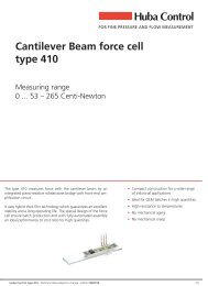
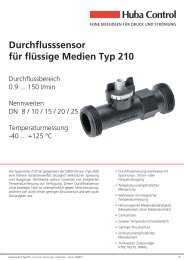
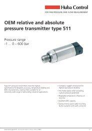
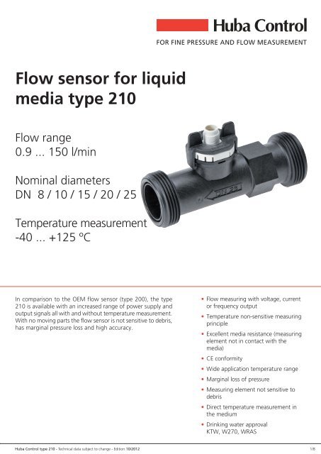
<strong>Flow</strong> <strong>sensor</strong> <strong>for</strong> <strong>liquid</strong><br />
<strong>media</strong> <strong>type</strong> <strong>210</strong><br />
<strong>Flow</strong> range<br />
0.9 ... 150 l/min<br />
Nominal diameters<br />
DN 8 / 10 / 15 / 20 / 25<br />
Temperature measurement<br />
-40 ... +125 ÀC<br />
In comparison to the OEM flow <strong>sensor</strong> (<strong>type</strong> 200), the <strong>type</strong><br />
<strong>210</strong> is available with an increased range of power supply and<br />
output signals all with and without temperature measurement.<br />
With no moving parts the flow <strong>sensor</strong> is not sensitive to debris,<br />
has marginal pressure loss and high accuracy.<br />
� <strong>Flow</strong> measuring with voltage, current<br />
or frequency output<br />
� Temperature non-sensitive measuring<br />
principle<br />
� Excellent <strong>media</strong> resistance (measuring<br />
element not in contact with the<br />
<strong>media</strong>)<br />
� CE con<strong>for</strong>mity<br />
� Wide application temperature range<br />
� Marginal loss of pressure<br />
� Measuring element not sensitive to<br />
debris<br />
� Direct temperature measurement in<br />
the medium<br />
� Drinking water approval<br />
KTW, W270, WRAS<br />
<strong>Huba</strong> <strong>Control</strong> <strong>type</strong> <strong>210</strong> - Technical data subject to change - Edition 10/2012 1/8
2/8<br />
Technical overview<br />
<strong>Flow</strong> measurement<br />
Measuring principle Vortex Piezoelectric <strong>sensor</strong> element<br />
Measuring range 0.9 ... 150 l/min<br />
Nominal diameters DN 8 / 10 / 15 / 20 / 25<br />
Accuracy at < 50% fs (water) < 1% fs<br />
Accuracy at > 50% fs (water) < 2% measuring value<br />
Im<strong>media</strong>tely<br />
Frequency output<br />
Signal delay < 100 ms<br />
Response time<br />
There<strong>for</strong>e suitable <strong>for</strong> spigot use.<br />
Analogue output<br />
Response time < 5 ms<br />
Signal delay < 2 s<br />
Response time < 500 ms<br />
Temperature measurement<br />
Measuring principle Resistance PT1000<br />
PT1000<br />
Measuring range<br />
Accuracy class B DIN EN 60751<br />
@ T = 0 ÀC<br />
@ T ≠ 0 ÀC<br />
-40 ... +125 ÀC<br />
μ 0.3 K<br />
μ 0.3 K μ 0.005 * T<br />
Measuring range -25 ... +125 ÀC<br />
0 ... 10 V<br />
Accuracy<br />
Calculation temperature<br />
μ 0.5 K μ 0.005 * T<br />
T (ÀC) = +150 ÀC * UOUT_T 10 V - 25 ÀC<br />
Temperature influences<br />
Self-heating at temperature <strong>sensor</strong><br />
Conduction resistance to connector<br />
1 K/mW<br />
0.8 Ohm<br />
Operating conditions<br />
Medium<br />
Suitable <strong>for</strong> heating circuit water with the usual additives<br />
Drinking water<br />
Other medium on request<br />
Temperature<br />
Media<br />
Ambient<br />
< +125 ÀC<br />
-15 ... +85 ÀC<br />
Storage -30 ... +85 ÀC<br />
(<strong>for</strong> lifetime) 12 bar at +40 ÀC<br />
Max. pressure and<br />
medium temperature<br />
(<strong>for</strong> lifetime)<br />
(<strong>for</strong> 600 hours)<br />
(<strong>for</strong> 2 hours)<br />
6 bar at +100 ÀC<br />
4 bar at +125 ÀC<br />
4 bar at +140 ÀC<br />
(max. test pressure) 18 bar at +40 ÀC<br />
Cavitation The following equation is valid to prevent cavitation: Pabs outlet / Pdifference > 5.5<br />
Materials in contact with medium (FDA-kon<strong>for</strong>m)<br />
Sensor paddle ETFE<br />
Case with damming body PA6T/6I (Grivory 40% GF)<br />
Sealing material EPDM (perox.)<br />
Electrical overview Frequency output Voltage output Current output<br />
Power supply UIN 4.75 ... 33 VDC 11.5 ... 33 VDC 8 ... 33 VDC<br />
Output Frequency square pulse signal UOUT_Q_frequency < 0.5 ... > UIN - 0.5 V � �<br />
<strong>Flow</strong> (Q) Analogue signal UOUT_Q oder IOUT � 0 ... 10 V 4 ... 20 mA<br />
Output Resistant signal ROUT PT1000 PT1000 class B DIN EN 60751<br />
temperature (T) Voltage signal UOUT_T � 0 ... 10 V �<br />
Electrical connection and protection class M12x1 (IP 65) M12x1 (IP 65) M12x1 (IP 65)<br />
Load agianst GND or IN < 1 mA / < 100 nF < 6 mA / < 100 nF 1) < (UIN - 8 V) / 20 mA<br />
Current consumption load free (IIN) < 2mA < 5 mA �<br />
Characteristic line: Frequency output Voltage output current output<br />
Characteristic line Frequency range Quantity per puls Characteristic line Characteristic line<br />
DN 8 Q = 0.0350 * f - 0.3 ~ 34 ... 437 Hz ~ 0.56 ml Q = 1.5 * UOUT_Q Q = 0.938 * (I - 4 mA)<br />
DN 10 Q = 0.0845 * f - 0.2 ~ 24 ... 382 Hz ~ 1.40 ml Q = 3.2 * UOUT_Q Q = 2.000 * (I - 4 mA)<br />
DN 15 Q = 0.1870 * f - 0.2 ~ 19 ... 269 Hz ~ 3.09 ml Q = 5.0 * UOUT_Q Q = 3.125 * (I - 4 mA)<br />
DN 20 Q = 0.3730 * f - 0.3 ~ 14 ... 229 Hz ~ 6.22 ml Q = 8.5 * UOUT_Q Q = 5.313 * (I - 4 mA)<br />
DN 25 Q = 0.7440 * f - 0.2 ~ 12 ... 202 Hz ~ 12.40 ml Q = 15.0 * UOUT_Q Q = 9.375 * (I - 4 mA)<br />
Nominal diameters dependent variables<br />
Measuring range <strong>Flow</strong> rate Pressure drop 2), 3) Weight<br />
DN 8 0.9 ... 15 l/min 0.30 ... 5.0 m/s Pv = 85.00 * Q 2 ~ 47 g<br />
DN 10 1.8 ... 32 l/min 0.32 ... 5.6 m/s Pv = 22.50 * Q 2 ~ 57 g<br />
DN 15 3.5 ... 50 l/min 0.33 ... 4.7 m/s Pv = 6.70 * Q 2 ~ 68 g<br />
DN 20 5.0 ... 85 l/min 0.29 ... 5.0 m/s Pv = 2.50 * Q 2 ~ 92 g<br />
DN 25 9.0 ... 150 l/min 0.33 ... 5.5 m/s Pv = 0.92 * Q 2 ~ 100 g<br />
Test / Admissions<br />
Drinking water approval KTW / W270 / WRAS<br />
Electromagnetic compatibility CE con<strong>for</strong>mity acc. to EN 61326-2-3<br />
Packaging (multiple packaging) Connection copper tube Outside thread K Outside thread G<br />
DN 8 / 10 Blister 30x Blister 30x Blister 30x<br />
DN 15 Blister 30x Blister 30x Blister 20x<br />
DN 20 Blister 20x Blister 20x Blister 15x<br />
DN25 � Blister 15x Blister 15x<br />
1) against GND only 2) incl. 3xDi inlet and outlet side 3) Pv in Pa; Q in l/min<br />
<strong>Huba</strong> <strong>Control</strong> <strong>type</strong> <strong>210</strong> - Technical data subject to change - Edition 10/2012
Order code selection table <strong>210</strong>. X X X X X X X<br />
Version <strong>Flow</strong> 9<br />
<strong>Flow</strong> and temperature (PT1000) 8<br />
<strong>Flow</strong> and temperature (0 ... 10 V) 6<br />
Nominal diameters and DN 8 0.9 ⁄ 15 l/min. 0 8<br />
flow range DN 10 1.8 ⁄ 32 l/min. 1 0<br />
DN 15 3.5 ⁄ 50 l/min. 1 5<br />
DN 20 5.0 ⁄ 85 l/min. 2 0<br />
DN 25 9.0 ⁄ 150 l/min. 2 5 K,G<br />
Output / power supply Frequency output (Square pulse signal) 4.75 ... 33 VDC 8,9 2<br />
Analogue signal 0 ... 10 V 11.5 ... 33 VDC 3<br />
Analogue signal 4 ... 20 mA 8 ... 33 VDC 8,9 4<br />
Electrical connection Connector M12x1 2- or 3-pole (condensation protection) 9 4<br />
Connector M12x1 4- or 5-pole (condensation protection) 8,6 5<br />
Sealing material EPDM Ethylene propylene rubber (peroxidically cross-linked) 1<br />
Tube connection Plastic PA6T / 6I connection copper tube (max. DN 20) N<br />
Plastic PA6T / 6I outside thread K (see dimension diagram) K<br />
Plastic PA6T / 6I outside thread G (see dimension diagram) G<br />
Accessories 1)<br />
Order number<br />
Connection kit 2) DN 8, 10 with copper tube 113775<br />
Connection kit 2) DN 8, 10 with adapter Rp ⅜ Stainless steel 1.4305/AISI 303 113776<br />
Connection kit 2) DN 15 with copper tube 113777<br />
Connection kit 2) DN 15 with adapter Rp ½ Stainless steel 1.4305/AISI 303 113778<br />
Connection kit 2) DN 20 with copper tube 113779<br />
Connection kit 2) DN 20 with adapter Rp ¾ Stainless steel 1.4305/AISI 303 113780<br />
Straight-wire box <strong>for</strong> connector M12x1 with cable 3-pole 200 cm 114605<br />
Corner-wire box <strong>for</strong> connector M12x1 with cable 3-pole 200 cm 114604<br />
Straight-wire box <strong>for</strong> connector M12x1 with cable 5-pole 200 cm (with temperature) 114564<br />
Corner-wire box <strong>for</strong> connector M12x1 with cable 5-pole 200 cm (with temperature) 114563<br />
Straight-wire box <strong>for</strong> connector M12x1 screwing terminal 5-pole 115024<br />
Clip <strong>for</strong> DN 8,10 112116<br />
Clip <strong>for</strong> DN 15 110941<br />
Clip <strong>for</strong> DN 20 112122<br />
O-Ring <strong>for</strong> DN 8, DN 10 EPDM Π13.95 x 2.62 Copper tube and adapter 112124<br />
O-Ring <strong>for</strong> DN 15 EPDM Π17.86 x 2.62 Copper tube and adapter 112265<br />
O-Ring <strong>for</strong> DN 20 EPDM Π21.89 x 2.62 Copper tube and adapter 112723<br />
O-Ring <strong>for</strong> DN 25 EPDM Π31 x 3 (as a replacement, already assembled) 112792<br />
Connection copper tube <strong>for</strong> DN 8, 10 L=150 mm 112121<br />
Connection copper tube <strong>for</strong> DN 15 L=150 mm 112211<br />
Connection copper tube <strong>for</strong> DN 20 L=150 mm 112306<br />
Adapter <strong>for</strong> DN 8 und DN 10 Rp ⅜ Stainless steel 1.4305/AISI 303 112655<br />
Adapter <strong>for</strong> DN 15 Rp ½ Stainless steel 1.4305/AISI 303 112660<br />
Adapter <strong>for</strong> DN 20 Rp ¾ Stainless steel 1.4305/AISI 303 112661<br />
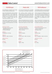
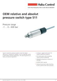
Minimum life span on high flow rate and high temperature<br />
Temperature in ÀC<br />
Temperatur in °C<br />
135<br />
130<br />
125<br />
120<br />
115<br />
110<br />
105<br />
100<br />
95<br />
90<br />
85<br />
80<br />
75<br />
70<br />
65<br />
60<br />
55<br />
50<br />
40<br />
60 80 100 120 140<br />
Durchfluss<br />
<strong>Flow</strong><br />
in %<br />
in %<br />
2 Std hours<br />
10 Std std<br />
100 Std std<br />
0.1 Jahr year<br />
1 Jahr year<br />
10 Jahre year<br />
1) Accessories supplied loose 2) Connection set includes: 2x Clip, 2x Copper tubes or Adapter and 2x O-Ring<br />
<strong>Huba</strong> <strong>Control</strong> <strong>type</strong> <strong>210</strong> - Technical data subject to change - Edition 10/2012 3/8
4/8<br />
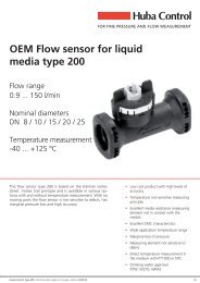
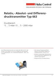
Dimension diagram DN 8, 10, 15, 20, 25<br />
1a<br />
1d<br />
3d 3d<br />
5d<br />
4a<br />
4d<br />
Dimension diagram DN 8, 10, 15, 20<br />
3a<br />
6a<br />
2a<br />
2d<br />
1d 2d 3d 4d 5d 6d<br />
DN8 K 43.7 53.0 G ½ 77 12 12<br />
DN8 G 48.2 55.7 G ¾ 86 12 12<br />
DN10 K 35.0 51.3 G ½ 81 12 19<br />
DN10 G 39.5 54.1 G ¾ 90 12 19<br />
DN15 K 36.6 56.1 G ¾ 87 16 22<br />
DN15 G 41.6 59.5 G 1 97 16 22<br />
DN20 K 36.6 61.5 G 1 105 20 27<br />
DN20 G 42.6 65.8 G 1¼ 117 20 27<br />
DN25 K 50.0 68.3 G 1¼ 120 26 34<br />
DN25 G 56.0 71.3 G 1½ 132 26 34<br />
5a<br />
1a 2a 3a 4a 5a 6a<br />
DN8 29.5 59.0 32.9 72 30.2 28.9<br />
DN10 32.5 57.3 32.9 77 30.2 28.9<br />
DN15 32.5 62.4 39.0 82 30.2 33.0<br />
DN20 39.3 66.3 43.0 105 30.2 37.4<br />
<strong>Huba</strong> <strong>Control</strong> <strong>type</strong> <strong>210</strong> - Technical data subject to change - Edition 10/2012<br />
6d
Accessories DN 8, 10, 15, 20<br />
6c<br />
o-ring<br />
to adapter<br />
DN8 22<br />
DN10 22<br />
DN15 24<br />
DN20 30<br />
Adapter 1.4305<br />
1c 2c 3c 4c 5c 6c 7c 8c 9c<br />
Rp ⅜ DIN 2999<br />
lenght min. 9<br />
Rp ⅜ DIN 2999<br />
lenght min. 9<br />
Rp ½ DIN 2999<br />
length min. 11.5<br />
Rp ¾ DIN 2999<br />
lenght min. 13<br />
Geometry of customers connection tube DN 8, 10, 15, 20<br />
Bevelled edge<br />
min. 0.1<br />
o-ring<br />
to adapter<br />
5c<br />
6b 5b 4b<br />
14.0 29 57.65 44.65 24.5 6.00 30.8<br />
14.0 29 59.65 47.55 24.5 6.00 30.8<br />
16.4 32 67.05 50.05 28.0 4.85 34.5<br />
3b<br />
2b<br />
1c<br />
4c<br />
3c<br />
18.5 38 82.25 58.85 28.0 8.00 34.5<br />
1b<br />
Inside thread<br />
1b 2b 3b 4b 5b 6b 7c 8c 9c<br />
DN8 Œ 13.95x262 2 μ 0.2 8.9 μ 0.2 Œ 13 μ 0.2 Œ 15.00 μ 0.08 Œ 18.88 μ 0.1 24.5 6.00 30.8<br />
DN10 Œ 13.95x262 2 μ 0.2 8.9 μ 0.2 Œ 13 μ0.2 Œ 15.00 μ 0.08 Œ 18.88 μ 0.1 24.5 6.00 30.8<br />
DN15<br />
Œ 17.86x2.62 2 μ 0.2 8.9 μ 0.3 Œ 16 μ 0.2<br />
+ 0.08 0.08<br />
Π18.00<br />
- 0.06<br />
Œ 21.85 μ 0.1 28.0 4.85 34.5<br />
DN20<br />
Œ 21.89x2.62 2 μ 0.2 12.9 μ 0.3 Œ 20 μ 0.2<br />
+ 0.08<br />
Π22.00<br />
- 0.06<br />
Œ 25.85 μ 0.1 28.0 8.00 34.5<br />
<strong>Huba</strong> <strong>Control</strong> <strong>type</strong> <strong>210</strong> - Technical data subject to change - Edition 10/2012 5/8<br />
2c<br />
Clip<br />
Clip<br />
9c<br />
7c<br />
9c<br />
7c<br />
8c<br />
8c
6/8<br />
Tube mounting instructions<br />
Consider the following to ensure the correct function of the <strong>sensor</strong>.<br />
� Only diameter changes from large to small are allowed.<br />
� Avoid repeated elbows in the same level at entryside<br />
Electrical connection<br />
Connector M12x1 without temperature measurement<br />
IN<br />
1<br />
Connector M12x1 with temperature measurement<br />
minimum 0.5xDN<br />
<strong>for</strong> recommended 90À<br />
elbow with min. R 1.8xDN<br />
Frequency output current output<br />
voltage output<br />
T2<br />
4<br />
3<br />
IN<br />
1<br />
2<br />
Ω<br />
5<br />
GND<br />
4<br />
3<br />
T1<br />
OUT<br />
GND<br />
frequency output<br />
with PT1000<br />
Hz<br />
Hz<br />
IN<br />
1<br />
T2<br />
4<br />
3<br />
GND<br />
IN<br />
1<br />
2<br />
Ω<br />
5<br />
A<br />
4<br />
3<br />
GND<br />
T1<br />
A<br />
current output<br />
with PT1000<br />
IN<br />
1 4 V<br />
2<br />
3<br />
T2<br />
1<br />
GND<br />
IN<br />
1<br />
2<br />
Ω<br />
OUT<br />
OUTQ<br />
5<br />
4<br />
3<br />
T1<br />
GND<br />
OUT<br />
voltage output<br />
with PT1000<br />
OUTQ<br />
minimum 5xDN<br />
<strong>for</strong> alternative elbows<br />
V<br />
Pin Colour<br />
1 brown<br />
3<br />
4<br />
1 blue<br />
black<br />
1 brown<br />
2 white<br />
3 2 blue<br />
4 black<br />
5 gray<br />
IN<br />
1<br />
2<br />
5<br />
4<br />
3<br />
GND<br />
OUTT<br />
OUTQ<br />
V<br />
V<br />
voltage output with<br />
temperature output 0 ...10 V<br />
<strong>Huba</strong> <strong>Control</strong> <strong>type</strong> <strong>210</strong> - Technical data subject to change - Edition 10/2012
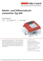
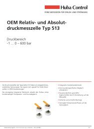
Influence of glycol<br />
With the following definitions we are able to correct the influence of <strong>media</strong> with higher viscosity than water (= <strong>media</strong> viscosity > 1.8 cST) in<br />
order to reach a measuring accuracy of 3% fs in the range of 1.8 - 4 cST and of 4% in the range of 4 - 14 cSt ( = viscosity in cSt).<br />
Temperature Temperatur�in�°C in ÀC<br />
Minimal Minimaler�Durchfluss�in�l/min<br />
flow in l/min<br />
Definition of viscosity of glycol-water-compound<br />
60<br />
50<br />
40<br />
30<br />
20<br />
10<br />
Formula respond threshold Q min in l/min<br />
DN 10: Qmin = υ + 0.8<br />
DN 15: Qmin = υ + 2.5<br />
DN 20: Qmin = υ + 4.0<br />
DN 25: Qmin = υ + 6.0<br />
Kinematic Kinematische�Viskosität�Ethylenglykol�Wasser<br />
viscosity ethylene glycol water Kinematic Kinematische�Viskosität�Propylenglykol�Wasser<br />
viscosity propylene glycol water<br />
0%<br />
10%<br />
20%<br />
30%<br />
40%<br />
50%<br />
60%<br />
70%<br />
0<br />
0<br />
1 2 3 4 5 6 7 8 9 10 11 12 13 14<br />
1 2 3 4 5 6 7 8 9 10 11 12 13 14<br />
viscosity Viskosität�in�cSt in cSt viscosity Viskosität�in�cSt in cSt<br />
Definition of respond threshold Qmin Definition of characteristic line <strong>for</strong>mula Q = k * f - Q 0<br />
25<br />
20<br />
15<br />
10<br />
5<br />
Minimal�detektierbarer�Durchfluss<br />
Temperature Temperatur�in�°C in ÀC<br />
Minimal detectable flow Einfluss�der�Viskosität�auf�Q Influence on viscocity Q0<br />
0<br />
0<br />
1 2 3 4 5 6 7 8 9 10 11 12 13 14<br />
viscosity Viskosität�in�cSt in cSt<br />
DN10<br />
DN15<br />
DN20<br />
DN25<br />
Formula characteristic line <strong>for</strong> Q > Qmin in l/min<br />
Frequency output:<br />
DN10: Q = 0.0845 * f � 0.40υ + 0.20<br />
DN15: Q = 0.1870 * f � 0.45υ + 0.25<br />
DN20: Q = 0.3730 * f � 0.55υ + 0.25<br />
DN25: Q = 0.7440 * f � 0.80υ + 0.60<br />
Voltage output 0 ...10 V<br />
DN10: Q = 3.2 * UOut � 0.40υ + 0.40<br />
DN15: Q = 5.0 * UOut � 0.45υ + 0.45<br />
DN20: Q = 8.5 * UOut � 0.55υ + 0.55<br />
DN25: Q = 15.0 * UOut � 0.80υ + 0.80<br />
60<br />
50<br />
40<br />
30<br />
20<br />
10<br />
characteristic Q0�in�Kennlinien<strong>for</strong>mel�in�l/min<br />
line <strong>for</strong>mula<br />
Current output 4 ... 20 mA (I in mA)<br />
DN10: Q = 2.000 * (I � 4 mA) - 0.40υ + 0.40<br />
DN15: Q = 3.125 * (I � 4 mA) - 0.45υ + 0.45<br />
DN20: Q = 5.313 * (I � 4 mA) - 0.55υ + 0.55<br />
DN25: Q = 9.375 * (I � 4 mA) - 0.80υ + 0.80<br />
12<br />
10<br />
8<br />
6<br />
4<br />
2<br />
0<br />
1 2 3 4 5 6 7 8 9 10 11 12 13 14<br />
viscosity Viskosität�in�cSt in cSt<br />
<strong>Huba</strong> <strong>Control</strong> <strong>type</strong> <strong>210</strong> - Technical data subject to change - Edition 10/2012 7/8<br />
0%<br />
10%<br />
20%<br />
30%<br />
40%<br />
50%<br />
60%<br />
DN10<br />
DN15<br />
DN20<br />
DN25
<strong>Huba</strong> <strong>Control</strong> AG<br />
Headquarters<br />
Industriestrasse 17<br />
5436 Würenlos<br />
Telefon +41 (0) 56 436 82 00<br />
Telefax +41 (0) 56 436 82 82<br />
info.ch@hubacontrol.com<br />
<strong>Huba</strong> <strong>Control</strong> AG<br />
Niederlassung Deutschland<br />
Schlattgrabenstrasse 24<br />
72141 Walddorfhäslach<br />
Telefon +49 (0) 7127 23 93 00<br />
Telefax +49 (0) 7127 23 93 20<br />
info.de@hubacontrol.com<br />
<strong>Huba</strong> <strong>Control</strong> SA<br />
Succursale France<br />
Rue Lavoisier<br />
Technopôle Forbach-Sud<br />
57602 Forbach Cedex<br />
Téléphone +33 (0) 387 847 300<br />
Télécopieur +33 (0) 387 847 301<br />
info.fr@hubacontrol.com<br />
<strong>Huba</strong> <strong>Control</strong> AG<br />
Vestiging Nederland<br />
Hamseweg 20A<br />
3828 AD Hoogland<br />
Telefoon +31 (0) 33 433 03 66<br />
Telefax +31 (0) 33 433 03 77<br />
info.nl@hubacontrol.com<br />
<strong>Huba</strong> <strong>Control</strong> AG<br />
Branch Office United Kingdom<br />
Unit 13 Berkshire House<br />
County Park Business Centre<br />
Shrivenham Road<br />
Swindon - Wiltshire SN1 2NR<br />
Phone +44 (0) 1993 776667<br />
Fax +44 (0) 1993 776671<br />
info.uk@hubacontrol.com<br />
www.hubacontrol.com