technical data
technical data
technical data

You also want an ePaper? Increase the reach of your titles
YUMPU automatically turns print PDFs into web optimized ePapers that Google loves.
�������������<br />
���������������������������� ������������������������<br />
���������<br />
����������<br />
���������<br />
Notes<br />
�����������<br />
�������<br />
�����������<br />
�����������<br />
����������� ������������������������<br />
�������<br />
�����������<br />
����������<br />
���������� � �������<br />
�����������<br />
���������� �<br />
���������<br />
���������� ���������� �������<br />
�����������<br />
����������<br />
���������<br />
��������� ���������<br />
����������������������������<br />
���������<br />
����������<br />
�������<br />
�����������<br />
���������� �������<br />
�����������<br />
����������<br />
���������<br />
����������<br />
����������<br />
�����������<br />
�����������<br />
�������<br />
�����������<br />
�������<br />
�����������<br />
���������� ����������<br />
�����������<br />
�����������<br />
����������<br />
����������<br />
����������<br />
���������� ����������<br />
����������<br />
����������<br />
�����������<br />
�����������<br />
�����������<br />
�����������<br />
�����������<br />
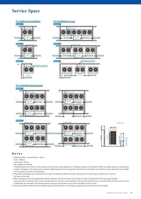
1. Heights of walls in case of Patterns 1 and 2 :<br />
Front : 1500mm<br />
Suction side : 500mm<br />
Side : Height unrestricted.<br />
Installation space to be shown in this drawing is based on the cooling operation at 35 degrees outdoor air temperature. When the design outdoor air temperature<br />
exceeds 35 degrees or the load exceeds maximum ability because of much generation load of heat in all outdoor unit, take the suction side space more broadly<br />
than the space to be shown in this drawing.<br />
2. If the above wall heights are exceeded then h2/2 and h1/2 should be added to the front and suction side service spaces respectively as shown in<br />
the figure on the right.<br />
3. When installing the units most appropriate pattern should be selected from those shown above in order to obtain the best fit in the space available<br />
always bearing in mind the need to leave enough space for a person to pass between units and wall and for the air to circulate freely. (If more units are to be<br />
installed than are catered for in the above patterns your layout should take account of the possibility of short circuits.)<br />
4. The units should be installed to leave sufficient space at the front for the on site refrigerant piping work to be carried out comfortably.<br />
�������<br />
������������������������<br />
������� ���������� ����������<br />
����������� �������<br />
�����������<br />
�����������<br />
�������<br />
�����������<br />
�����������<br />
����������<br />
�����������<br />
�������<br />
����������� �����������<br />
����������<br />
�����������<br />
����������<br />
����������<br />
����������<br />
���������� ����������� �������<br />
�����������<br />
����������� ����������<br />
��<br />
������<br />
�������<br />
�����������<br />
��������������<br />
��<br />
�����<br />
Outdoor Unit Layout Guide 10<br />
���������