HiTeC & Yokogawa - emitec-industrial.ch
HiTeC & Yokogawa - emitec-industrial.ch
HiTeC & Yokogawa - emitec-industrial.ch

Create successful ePaper yourself
Turn your PDF publications into a flip-book with our unique Google optimized e-Paper software.
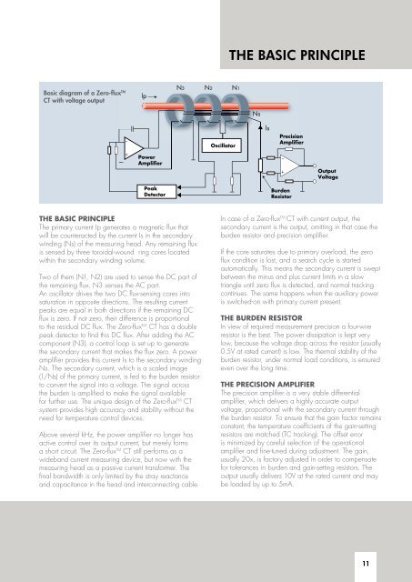
Basic diagram of a Zero-flux TM<br />
CT with voltage output<br />
the basic PrinciPle<br />
The primary current Ip generates a magnetic flux that<br />
will be counteracted by the current Is in the secondary<br />
winding (Ns) of the measuring head. Any remaining flux<br />
is sensed by three toroidal-wound ring cores located<br />
within the secondary winding volume.<br />
Two of them (N1, N2) are used to sense the DC part of<br />
the remaining flux. N3 senses the AC part.<br />
An oscillator drives the two DC flux-sensing cores into<br />
saturation in opposite directions. The resulting current<br />
peaks are equal in both directions if the remaining DC<br />
flux is zero. If not zero, their difference is proportional<br />
to the residual DC flux. The Zero-flux TM CT has a double<br />
peak detector to find this DC flux. After adding the AC<br />
component (N3), a control loop is set up to generate<br />
the secondary current that makes the flux zero. A power<br />
amplifier provides this current Is to the secondary winding<br />
Ns. The secondary current, whi<strong>ch</strong> is a scaled image<br />
(1/Ns) of the primary current, is fed to the burden resistor<br />
to convert the signal into a voltage. The signal across<br />
the burden is amplified to make the signal available<br />
for further use. The unique design of the Zero-flux TM CT<br />
system provides high accuracy and stability without the<br />
need for temperature control devices.<br />
Above several kHz, the power amplifier no longer has<br />
active control over its output current, but merely forms<br />
a short circuit. The Zero-flux TM CT still performs as a<br />
wideband current measuring device, but now with the<br />
measuring head as a passive current transformer. The<br />
final bandwidth is only limited by the stray reactance<br />
and capacitance in the head and interconnecting cable.<br />
THe baSiC PrinCiPle<br />
In case of a Zero-flux TM CT with current output, the<br />
secondary current is the output, omitting in that case the<br />
burden resistor and precision amplifier.<br />
If the core saturates due to primary overload, the zero<br />
flux condition is lost, and a sear<strong>ch</strong> cycle is started<br />
automatically. This means the secondary current is swept<br />
between the minus and plus current limits in a slow<br />
triangle until zero flux is detected, and normal tracking<br />
continues. The same happens when the auxiliary power<br />
is swit<strong>ch</strong>ed-on with primary current present.<br />
the burDen resistor<br />
In view of required measurement precision a four-wire<br />
resistor is the best. The power dissipation is kept very<br />
low, because the voltage drop across the resistor (usually<br />
0.5V at rated current) is low. The thermal stability of the<br />
burden resistor, under normal load conditions, is ensured<br />
even over the long time.<br />
the Precision amPlifier<br />
The precision amplifier is a very stable differential<br />
amplifier, whi<strong>ch</strong> delivers a highly accurate output<br />
voltage, proportional with the secondary current through<br />
the burden resistor. To ensure that the gain factor remains<br />
constant, the temperature coefficients of the gain-setting<br />
resistors are mat<strong>ch</strong>ed (TC tracking). The offset error<br />
is minimized by careful selection of the operational<br />
amplifier and fine-tuned during adjustment. The gain,<br />
usually 20x, is factory adjusted in order to compensate<br />
for tolerances in burden and gain-setting resistors. The<br />
output usually delivers 10V at the rated current and may<br />
be loaded by up to 5mA.<br />
11